WO2014050939A1 - Structure de stator dans un générateur - Google Patents
Structure de stator dans un générateur Download PDFInfo
- Publication number
- WO2014050939A1 WO2014050939A1 PCT/JP2013/076000 JP2013076000W WO2014050939A1 WO 2014050939 A1 WO2014050939 A1 WO 2014050939A1 JP 2013076000 W JP2013076000 W JP 2013076000W WO 2014050939 A1 WO2014050939 A1 WO 2014050939A1
- Authority
- WO
- WIPO (PCT)
- Prior art keywords
- stator core
- coil end
- coil
- slots
- stator
- Prior art date
Links
Images


Classifications
-
- H—ELECTRICITY
- H02—GENERATION; CONVERSION OR DISTRIBUTION OF ELECTRIC POWER
- H02K—DYNAMO-ELECTRIC MACHINES
- H02K1/00—Details of the magnetic circuit
- H02K1/06—Details of the magnetic circuit characterised by the shape, form or construction
- H02K1/12—Stationary parts of the magnetic circuit
- H02K1/18—Means for mounting or fastening magnetic stationary parts on to, or to, the stator structures
- H02K1/185—Means for mounting or fastening magnetic stationary parts on to, or to, the stator structures to outer stators
-
- H—ELECTRICITY
- H02—GENERATION; CONVERSION OR DISTRIBUTION OF ELECTRIC POWER
- H02K—DYNAMO-ELECTRIC MACHINES
- H02K3/00—Details of windings
- H02K3/46—Fastening of windings on the stator or rotor structure
- H02K3/50—Fastening of winding heads, equalising connectors, or connections thereto
-
- H—ELECTRICITY
- H02—GENERATION; CONVERSION OR DISTRIBUTION OF ELECTRIC POWER
- H02K—DYNAMO-ELECTRIC MACHINES
- H02K3/00—Details of windings
- H02K3/46—Fastening of windings on the stator or rotor structure
- H02K3/52—Fastening salient pole windings or connections thereto
- H02K3/527—Fastening salient pole windings or connections thereto applicable to rotors only
-
- H—ELECTRICITY
- H02—GENERATION; CONVERSION OR DISTRIBUTION OF ELECTRIC POWER
- H02K—DYNAMO-ELECTRIC MACHINES
- H02K5/00—Casings; Enclosures; Supports
- H02K5/04—Casings or enclosures characterised by the shape, form or construction thereof
- H02K5/16—Means for supporting bearings, e.g. insulating supports or means for fitting bearings in the bearing-shields
- H02K5/161—Means for supporting bearings, e.g. insulating supports or means for fitting bearings in the bearing-shields radially supporting the rotary shaft at both ends of the rotor
-
- H—ELECTRICITY
- H02—GENERATION; CONVERSION OR DISTRIBUTION OF ELECTRIC POWER
- H02K—DYNAMO-ELECTRIC MACHINES
- H02K5/00—Casings; Enclosures; Supports
- H02K5/24—Casings; Enclosures; Supports specially adapted for suppression or reduction of noise or vibrations
-
- H—ELECTRICITY
- H02—GENERATION; CONVERSION OR DISTRIBUTION OF ELECTRIC POWER
- H02K—DYNAMO-ELECTRIC MACHINES
- H02K9/00—Arrangements for cooling or ventilating
- H02K9/14—Arrangements for cooling or ventilating wherein gaseous cooling medium circulates between the machine casing and a surrounding mantle
Definitions
- a plurality of slots are provided on the inner periphery of a stator core surrounding a rotor fixed to a rotating shaft, and a plurality of slots are accommodated in slots spaced apart in the circumferential direction of the stator core with a plurality of slots interposed therebetween.
- a coil comprising a plurality of coil end portions arranged on the outer sides in the axial direction of the stator core is wound around the stator core, and a cooling fan for circulating cooling air through the stator core is rotated.
- the present invention relates to a generator fixed to a shaft, and more particularly to improvement of a stator structure.
- a generator stator in which a plurality of coil end portions are arranged in an annular arrangement having an inner diameter larger than the inner diameter of the starter core and arranged at both ends of the stator core is already known from Patent Document 1 and the like. Yes.
- Patent Document 1 in the structure in which a plurality of coil end portions are arranged at both ends of the stator core so as to have an annular arrangement having an inner diameter larger than the inner diameter of the starter core, the length of the coil end portion is long. Not only does the copper length increase, but the area of the coil end that comes into contact with the outside air becomes relatively small, making it difficult to dissipate heat from the coil end.
- the present invention has been made in view of such circumstances, and the length of the coil end portion is shortened to reduce the amount of copper, and the cooling effect can be improved by increasing the heat radiation area of the coil end portion.
- An object is to provide a stator structure in a generator.
- a plurality of slots are provided on the inner periphery of a stator core that surrounds a rotor fixed to a rotating shaft, and a plurality of slots are interposed between each other in the circumferential direction of the stator core.
- a coil in which a plurality of coil side portions accommodated in spaced apart slots are connected by a plurality of coil end portions arranged outside the both axial ends of the stator core is wound around the stator core, and cooling air is contained in the stator core.
- the one end side along the axial direction of the stator core is 2 inward from the inner periphery of the stator core as viewed from the direction along the axis of the rotating shaft.
- a plurality of coil end portions that connect the two slots by shortcuts are dispersed so that an opening that allows the rotation shaft to pass therethrough is formed in the central portion.
- the first feature to be location.
- the present invention provides a support member having a plurality of fitting recesses, the coil end portions being connected to the fitting recesses in order to maintain a distributed arrangement of the plurality of coil end portions.
- the second feature is that each of the coil end portions is attached so as to be fitted to each other.
- a plurality of coil end portions form a shortcut between the two slots while forming an opening that allows the rotation shaft to pass therethrough. Therefore, the length of the coil end portion can be shortened to reduce the amount of copper, and the cooling effect by the cooling air flowing through the stator core can be improved. Since the coil end portions are dispersedly arranged, the heat dissipation area of the coil end portions can be increased and a more excellent cooling effect can be obtained.
- the plurality of coil end portions are fitted into the plurality of fitting recesses of the support member to maintain the distributed arrangement state of each coil end portion, the number of parts is increased.
- the distributed arrangement of the plurality of coil end portions can be easily maintained while suppressing the above.
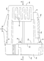
- FIG. 1 is a side view of the generator according to the first embodiment.
- FIG. 2 is a view taken in the direction of arrow 2 in FIG.
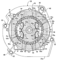
- FIG. 3 is a view taken in the direction of arrow 3 in FIG.
- First embodiment 4 is a cross-sectional view taken along line 4-4 of FIG.
- First embodiment 5 is a cross-sectional view taken along line 5-5 of FIG.
- First embodiment 6 is a perspective view of the first bracket.
- FIG. 7 is a perspective view of the second bracket.
- FIG. 8 is a perspective view of the rotor and the cooling fan.
- (First embodiment) 9 is a cross-sectional view taken along line 9-9 of FIG. (First embodiment) FIG.
- FIG. 10 is a perspective view of the bobbin half.
- (First embodiment) 11 is a cross-sectional view of the rotor taken along line 11-11 in FIG.
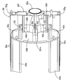
- FIG. 12 is a perspective view of the stator.
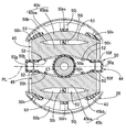
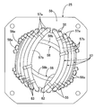
- FIG. 13 is a front view of one end of the stator as viewed from the direction along the axis of the rotating shaft.
- FIG. 14 is a view corresponding to FIG. 3 in a state in which a vibration-proof rubber is attached to the attachment portion.
- FIG. 15 is a view corresponding to FIG. 3 in a state in which a mounting leg is mounted on the mounting portion.
- FIG. 16 is a view corresponding to FIG.
- FIG. 17 is a perspective view of a stator corresponding to FIG. 12 of the second embodiment.
- FIGS. 1 to 16 The first embodiment of the present invention will be described with reference to FIGS. 1 to 16.
- the housing 21 of the generator is coupled to the first bracket 22 and the first bracket 22.
- a cover 24 attached to the first bracket 22 on the opposite side of the second bracket 23.
- a stator 25 is fixed to the first bracket 22 of the housing 21, and one end portion of the rotating shaft 27 is connected to the ball bearing 28 on the bearing portion 22 a of the first bracket 22.
- a rotor 26 that is rotatably supported through the stator 25 and is surrounded by the stator 25 is fixed to the rotary shaft 27, and a cooling fan 29 that rotates together with the rotary shaft 27 is covered with the second bracket 23.
- the first bracket 22 has a substantially cylindrical shape surrounding the bearing portion 22 a formed in a short cylindrical shape so as to fit the outer ring 28 a of the ball bearing 28 and the stator 25.
- the cylindrical portion 22b and one end of the cylindrical portion 22b are spaced apart in the circumferential direction of the bearing portion 22a, for example, four locations, and the other end is spaced in the circumferential direction of the one end portion of the cylindrical portion 22b.
- a retaining ring 30 for preventing axial movement of the ball bearing 28 in the bearing portion 22a is interposed.
- the second bracket 23 has a cylindrical side wall portion 23a whose one end is coupled to the cylindrical portion 22b of the first bracket 22, and a radius from the other end of the side wall portion 23a.
- An inward flange 23b projecting inward in the direction is integrally formed, and a circular opening 31 is formed on the inner periphery of the inward flange 23b.
- a flat outward flange 22d is integrally provided so as to protrude outward, and on the outer periphery of the outward flange 22d.
- a coupling protrusion 22e that slightly protrudes toward the second bracket 23 so as to abut one end of the side wall 23a is formed in one piece.
- the coupling protrusion 22e of the first bracket 22 is bolts 32, 32... Arranged at a plurality of locations spaced in the circumferential direction of the cylindrical portion 22b, and the side wall portion 23a of the second bracket 23.
- the second bracket 23 is attached to a drive source having a crankshaft 34 as a drive shaft connected coaxially to the rotary shaft 27, for example, an engine body 35 of the internal combustion engine E.
- the flange 23b is provided with a plurality of, for example, four fastening holes 36, 36,... Disposed around the opening 31, and the second bracket 23 has bolts 37, which are inserted into the fastening holes 36, 36,. 37... Are fastened to the engine body 35 at 37.
- the rotary shaft 27 has a tapered hole 38 at the end on the internal combustion engine E side, and is formed in a cylindrical shape.
- the rotary shaft 27 is inserted into the second bracket 23 through the opening 31.
- a tapered portion 34a at the end of the crankshaft 34 is fitted coaxially into the tapered hole 38, and a bolt 39 inserted into the rotating shaft 27 from the cover 24 side is screwed into the crankshaft 34 and tightened.
- the rotary shaft 27 is coaxially connected to the crankshaft 34 so as not to be relatively rotatable.
- the first bracket 22 is fastened to the engine body 35 in a state where the rotor 25 is fixed to a rotating shaft 27 to which the stator 25 is fixed and one end portion is rotatably supported by the bearing portion 22a.
- the two end portions of a plurality of, for example, two knock pins 40 for positioning the rotary shaft 27 and the crankshaft 34 to be aligned with each other. are provided in the coupling protrusion 22e of the first bracket 22 and the side wall 23a of the second bracket 23, respectively.
- the rotor 26 is formed by laminating a plurality of electromagnetic steel plates, and on a rotor core 43 fixed to the rotary shaft 27, a plane passing through the central axis of the rotary shaft 27.
- Field coils 45, 45 arranged on both sides of the PL are wound around a bobbin 44.
- One end of the rotating shaft 27 is press-fitted into an inner ring 28b of the ball bearing 28, and a pair of fields is provided on the outer periphery of a slip ring support 46 fixed to the rotating shaft 27 between the ball bearing 28 and the rotor 26.
- a pair of slip rings 47, 47 electrically connected to the magnetic coils 45, 45 are provided at intervals in the axial direction of the rotary shaft 27 and are supported by the first bracket 22 as shown in FIG. 4.
- a pair of brushes 49, 49 held by the brush holder 48 are in sliding contact with the slip rings 47, 47 individually.
- the bobbin 44 is attached to the rotor core 43 such that a pair of bobbin halves 50 and 50 formed in the same shape by a synthetic resin sandwich the rotor core 43 from both sides in a direction along the axis of the rotating shaft 27. Become.
- the bobbin half 50 includes a cylindrical support portion 50 a through which the rotation shaft 27 is inserted outside the rotor core 43 along the axis of the rotation shaft 27, and the rotation shaft 27.
- a pair of ends that are connected to both sides of the inner end of the cylindrical support portion 50a so as to extend along the one plane PL passing through the central axis, and that are opposed to and contact the outer end of the rotor core 43 along the axis of the rotary shaft 27.
- the plate portions 50b, 50b, and two ends of the end plate portions 50b are connected to the longitudinal ends on the one plane PL side.
- the inner side plate portions 50c, 50c,..., The outer side plate portions 50d, 50d, ... facing the inner side plate portions 50c, 50c, ..., and the inner side plate portions 50c, 50c, ... and the inner side plate portions 50d, 50d, ... are connected. Opening grooves 51, 51 ... are formed respectively by the bottom plate portions 50e, 50e ..., and two pairs of grooves 51, 51 ... which make a pair in the direction along the one plane PL are the bobbin half 50, that is, the bobbin. 44. Further, the inner regulating plate portions 50f, 50f are provided with flow holes 52, 52... Located on both sides of the cylindrical support portion 50a, and the flow holes 52, 52 are in a direction along the axis of the rotary shaft 27. Are formed integrally with the bobbin half 50.
- coil sides 45 a and 45 a of the field coil 45 are accommodated in the grooves 51 and 51 that form a pair in the direction along the one plane PL passing through the central axis of the rotating shaft 27.
- the coil end portions 45b and 45b at both ends of the field coil 45 are restricted from moving toward the one plane PL by the inner regulating plate portion 50f so as to connect the paired coil side portions 45a and 45a. It arrange
- the coil ends 45b and 45b of the field coil 45 are formed on the bobbin 44 at the portion corresponding to the outer end of the rotor core 43, as shown in FIG.
- Separating projections 50i, 50i are provided to divide the outer side portion 45ba ... and the outer side portion 45bb ..., and the inner projections are formed on both sides of the separating projections 50i, 50i along the circumferential direction of the rotary shaft 27.
- Gaps 53 are formed between the side portions 45ba and the outer side portions 45bb, respectively.
- the end plate portion 50b of the bobbin 44 has support bases 50j and 50j that protrude from the central portion in the longitudinal direction outward in the axial direction of the rotary shaft 27 and support the coil end portions 45b and 45b.
- the air passages 54 and 54 are formed between the coil end portions 45b and the end plate portions 50b on both sides of the support bases 50j and 50j along the circumferential direction of the rotary shaft 27, and are integrated with the end plate portion 50b.
- the separation protrusions 50i are projected from the support base 50j.
- air passages 54, 54 formed between the coil end portion 45 b and the end plate portion 50 b on both sides of the support base 50 j are formed at the outer ends along the radial direction of the rotating shaft 27 and the support base 50 j and
- the inner ends of the air passages 54, 54 that open to the outside of the rotor 26 through the space between the outer restricting protrusions 50 k, 50 k and extend along the radial direction of the rotating shaft 27 are provided in the inner restricting plate portion 50 f. It is opened to the outside of the rotor 26 at the outer end along the axial direction of the rotary shaft 27 through the flow holes 52.
- the stator 25 includes a plurality of output coils 57, 57... And a pair of stator coils 56, which are formed by laminating a plurality of electromagnetic steel plates and provided with a plurality of slots 55.
- the exciting coils 58 and 58 are wound.
- stator 25 is fixed to the first bracket 22 so as to be surrounded by the cylindrical portion 22b of the first bracket 22, and the cooling air sucked by the cooling fan 29 is the rotor 26.
- the stator 25 can be circulated between the outer periphery of the stator 25 and the inner periphery of the cylindrical portion 22b.
- a plurality of circumferential locations, for example, four locations on the outer periphery of the stator core 56 are press-fitted into the cylindrical portion 22b.
- the inner periphery of the cylindrical portion 22b is tapered with the second bracket 23 side as the maximum diameter in order to facilitate the insertion of the stator core 56 into the cylindrical portion 22b from the second bracket 23 side.
- the press-fit portions 59 for press-fitting the outer periphery of the stator core 56 are provided at four locations spaced in the circumferential direction of the intermediate portion of the cylindrical portion 22b.
- the press-fit portions 59 have the press-fit surfaces 60 extending along the axis of the rotary shaft 27 at the tip and extend in parallel to the direction along the axis of the rotary shaft 27. It is composed of two or three ridges 61, 61 ... projecting integrally on the inner surface of 22b, and between each of the ridges 61, 61 ... between the outer circumference of the stator 25 and the inner circumference of the cylindrical portion 22b.
- the cooling air can be circulated.
- the plurality of output coils 57, 57... And the pair of exciting coils 58, 58 are separated from each other in the circumferential direction of the stator core 56 with a plurality of slots 55, 55.
- a plurality of coil side portions 57a, 57a,... 58a, 58a,... Accommodated in 55, 55 are arranged outside the both axial ends of the stator core 56.
- stator core 56 is located on the inner side of the inner periphery of the stator core 56 when viewed from the direction along the axis of the rotary shaft 27.
- the fastener 63 an electrically insulated adhesive tape or lacing yarn may be used.
- the cooling fan 29 includes a cylindrical mounting tube portion 29 a that is fitted and fixed to the rotating shaft 27 in the second bracket 23, and the rotor 26.
- a taper tube portion 29b having a small diameter end connected to the mounting tube portion 29a so as to increase in diameter in the opposite direction, and a base end at a circumferentially spaced position on the outer periphery of the taper tube portion 29b Are formed in a ring shape so as to face the cooling fan 29 side end of the stator 25 and on the outer periphery of the plurality of blades 29c, 29c.
- a ring plate-like partition plate 29d provided in common is integrally provided, and a plurality of reinforcing ribs 29e, 29e,... Are integrally protruded from the inner periphery of the tapered cylindrical portion 29b.
- a discharge cylinder part 23c for discharging the cooling air discharged from the cooling fan 29 to the side is integrally provided at the lower part of the second bracket 23, and an outer end opening of the discharge cylinder part 23c is provided. Is provided with a louver 64 that divides the outer end opening into a plurality of sections.
- the cover 24 has a cylindrical side wall portion 24a and an end wall portion 24b that closes the outer end of the side wall portion 24a.
- the first bracket 22 is formed in a cylindrical shape and is fastened with bolts 65 and 65 to cylindrical boss portions 22f and 22f provided integrally on both sides of the bearing portion 22a in the first bracket 22. Fixed to.
- a plurality of first suction holes 66, 66... Opened downward are provided in the lower part of the side wall 24 a of the cover 24.
- a plurality of second suction holes 67 extending in the direction along the axis of the rotary shaft 27 are provided on both sides of the side wall portion 23a with a space therebetween in the vertical direction.
- 67... Are concealed in a side view, and flanges 24 c, 24 c... Projecting from the upper edges of the second suction holes 67, 67.
- the end wall portion 24b of the cover 24 is provided with a plurality of third suction holes 68, 68... By the operation of the cooling fan 29, and the first suction holes 66, 66. The cooling air is sucked into the housing 21 through the third suction holes 68, 68.
- one end portion of the first bracket 22, that is, the lower portion of the end portion on the cover 24 side, is a flat surface facing the cover 24 side so as to be disposed below the cover 24 when viewed from the cover 24 side.
- a pair of left and right mounting portions 22g, 22g having mounting surfaces 70, 70 are integrally provided.
- the mounting portions 22g and 22g are provided with a pair of vibration isolating rubbers 72, 72 for bolts 71, 72 for supporting the generator on the mount 69 via the vibration isolating rubbers 72, 72, for example.
- the mounting legs 73 are attached with a pair of bolts 71 and 71, and as shown in FIG.
- the state in which the stay 74 for mounting the exhaust muffler and the anti-vibration rubbers 72, 72 can be switched together by a pair of bolts 71, 71 can be switched, and the support legs of the generator can be made versatile. Can do.
- the first bracket 22 having a bearing portion 22a that pivotally supports one end of the rotating shaft 27, and the second bracket that covers the cooling fan 29 that rotates together with the rotating shaft 27.
- the stator 25 is fixed to a housing 21 having a stator 23, and the rotor 26 surrounded by the stator 25 is fixed to the rotating shaft 27.
- the stator 25 is fixed to the first bracket 22, and the A cylindrical portion 22b surrounding the stator 25 is integrally provided so that the cooling air sucked by the cooling fan 29 is circulated between the outer periphery of the stator 25, and the second bracket 23 is connected to the cylindrical portion. 22b, the cooling air is circulated along the outer periphery of the stator 25 to increase the cooling efficiency of the stator 25, and the long through-bolt
- the so as to couple the first and second brackets 22 and 23 without using the cost can be reduced.
- stator 25 since a plurality of circumferential positions on the outer periphery of the stator 25 are press-fitted into the cylindrical portion 22b, the number of parts can be reduced when the stator 25 is fixed to the first bracket 22.
- the cooling fan 29 is provided with a ring-plate-shaped partition plate 29d facing the end of the stator 25 on the cooling fan 29 side, the circulation of the cooling air that has circulated along the outer periphery of the stator 25 By changing the direction to the rotating shaft 27 side at the end of the stator 25 on the cooling fan 29 side, the end of the stator 25 on the cooling fan 29 side can be effectively cooled with cooling air.
- the second bracket 23 fastened to the engine body 35 of the internal combustion engine E including the crankshaft 34 coaxially connected to the rotary shaft 27 and one end portion of the rotary shaft 27 are rotated by the bearing portion 22a of the first bracket 22.
- both ends of a plurality of knock pins 40 for positioning the shafts of the rotary shaft 27 and the crankshaft 34 together are fitted. Since the positioning holes 41..., 42... Are provided in the first and second brackets 22 and 23, respectively, the concave and convex fitting portions are not required as compared with the case where the first and second brackets 22 and 23 are fitted and positioned. Further, it is possible to further increase the cooling effect by increasing the outer diameter of the cooling fan 29 without increasing the outer shape of the second bracket 23.
- the rotor 26 has field coils 45, 45 arranged on both sides of a plane PL passing through the central axis of the rotary shaft 27 on a bobbin 44 attached to the rotor core 43 fixed to the rotary shaft 27.
- the bobbin 44 is configured to be wound and corresponds to the outer end of the rotor core 43 in the axial direction.
- the coil end portions 45b at both ends of the field coils 45 along the axial direction of the rotary shaft 27 are provided on the bobbin 44.
- 45b are separated into an inner portion 45ba along the radial direction of the rotary shaft 27 and an outer portion 45bb..., 45b, along the circumferential direction of the rotary shaft 27.
- gaps 53 are formed between the inner side portions 45ba and the outer side portions 45b on both sides of the separation protrusions 50i, respectively, the heat dissipation area of the coil end portion 45b of the field coil 45 is formed. Increases, the coil end portions 45b and thus the field coil 45 effectively cooled, thereby improving the power generation efficiency.
- the field plate is raised from the end plate portions 50b of the bobbin 44 so as to face and abut the outer end of the rotor core 43 in the axial direction of the rotary shaft 27 from the end plate portions 50b.
- a support base 50j for supporting the coil end portion 45b of the coil 45 is provided between the coil end portion 45b and the end plate portion 50b on both sides of the support base 50j along the circumferential direction of the rotary shaft 27.
- the separation protrusion 50i is provided on the support base 50j. Therefore, the heat dissipation area of the coil end portion 45b is further increased, and the coil end portion 45b is formed. As a result, the field coil 45 can be cooled more effectively, and the power generation efficiency can be further improved.
- a plurality of slots 55, 55... are provided on the inner periphery of the stator core 56 surrounding the rotor 26 fixed to the rotary shaft 27, and the plurality of slots 55, 55.
- a plurality of coil side portions 57a, 57a,... 58a, 58a,... Housed in slots 55, 55 spaced apart from each other are arranged on the outer sides in the axial direction of the stator core 56.
- a pair of exciting coils 58, 58 connected by 58 b, 58 b are wound around the stator core 56, and at one end side along the axial direction of the stator core 56, the rotating shaft A plurality of coils that connect the two slots in a shortcut manner inwardly of the inner periphery of the stator core 56 as viewed from the direction along the axis 27
- the end portions 57b, 57b,... 58b, 58b are dispersedly arranged so as to form an opening 62 allowing the insertion of the rotating shaft 27 at the center, so that the coil end portions 57b, 57b,.
- the amount of copper can be reduced by reducing the length of the coil, and the cooling effect by the cooling air flowing through the stator core 56 can be improved, and the heat dissipation of the coil end portions 57b, 57b,.
- the area can be increased and a more excellent cooling effect can be obtained.
- FIG. 17 A second embodiment of the present invention will be described with reference to FIG. 17.
- a plurality of coil end portions 57 b, 57 b, 58 b, 58 b are connected to the rotary shaft 27 ( (See the first embodiment), the two slots 55, 55 are arranged so as to be short-cut and connected to the inside of the stator core 56 as seen from the direction along the axis. .. Are attached to the coil end portions 57b, 57b... 58b, 58b.
- the coil end portions 57b, 57b,..., 58b, 58b are fitted into the fitting recesses 81, 81... Of the binding member 80, so that the opening 62 is formed at the center.
- the end portions 57b, 57b ..., 58b, 58b are maintained in a distributed state, and the coil end portions 57b, 57b ...; 58b, 58b are impregnated with varnish while the binding members 80 are attached. Fixed to each other.
- the distributed arrangement of the plurality of coil end portions 57b, 57b,..., 58b, 58b can be easily maintained while suppressing an increase in the number of parts.
Abstract
Dans le générateur de l'invention, une pluralité de fentes est agencée à la périphérie interne d'un noyau de stator entourant un rotor fixé sur un axe de rotation. Autour du noyau de stator, est enroulée une bobine constituée par raccordement à l'aide d'une pluralité de parties extrémité de bobine ; et une pluralité de parties bord de bobine de ces parties extrémité de bobine, est admise dans les fentes séparées dans la direction radiale du noyau de stator, et est disposée vers l'extérieur des deux extrémités de direction axiale du noyau de stator avec la pluralité de fentes pour intermédiaire. En outre, un ventilateur de refroidissement faisant s'écouler un air de refroidissement à l'intérieur du noyau de stator, est fixé sur l'axe de rotation. Une pluralité de parties extrémité de bobine (57b, 58b) reliant en court-circuit deux fentes (55) côté interne par rapport à la périphérie interne du noyau de stator (56) selon une vue suivant une ligne axiale de l'axe de rotation, est disposée de manière dispersée, d'un côté extrémité suivant la direction axiale du noyau de stator (56), de manière à former dans une partie centrale une partie ouverture (62) autorisant l'insertion d'un axe de rotation. Ainsi, il est possible de réaliser une réduction de la quantité de cuivre en raccourcissant la longueur des parties extrémité de bobine, et une amélioration des résultats de refroidissement en augmentant la surface de dissipation de chaleur des parties extrémité de bobine.
Priority Applications (1)
| Application Number | Priority Date | Filing Date | Title |
|---|---|---|---|
| CN201380050938.8A CN104756369A (zh) | 2012-09-27 | 2013-09-26 | 发电机中的定子结构 |
Applications Claiming Priority (2)
| Application Number | Priority Date | Filing Date | Title |
|---|---|---|---|
| JP2012-214188 | 2012-09-27 | ||
| JP2012214188A JP6037108B2 (ja) | 2012-09-27 | 2012-09-27 | 発電機におけるステータ構造 |
Publications (1)
| Publication Number | Publication Date |
|---|---|
| WO2014050939A1 true WO2014050939A1 (fr) | 2014-04-03 |
Family
ID=50388334
Family Applications (1)
| Application Number | Title | Priority Date | Filing Date |
|---|---|---|---|
| PCT/JP2013/076000 WO2014050939A1 (fr) | 2012-09-27 | 2013-09-26 | Structure de stator dans un générateur |
Country Status (3)
| Country | Link |
|---|---|
| JP (1) | JP6037108B2 (fr) |
| CN (1) | CN104756369A (fr) |
| WO (1) | WO2014050939A1 (fr) |
Citations (4)
| Publication number | Priority date | Publication date | Assignee | Title |
|---|---|---|---|---|
| JPS53127605A (en) * | 1977-04-13 | 1978-11-08 | Hitachi Ltd | Stator of motor |
| JPS5778250U (fr) * | 1980-10-27 | 1982-05-14 | ||
| JP2000278903A (ja) * | 1999-03-26 | 2000-10-06 | Nissan Motor Co Ltd | 電動機及びその製造方法 |
| JP2003061291A (ja) * | 2001-08-10 | 2003-02-28 | Sawafuji Electric Co Ltd | 発動発電機用ブラケット構造 |
Family Cites Families (2)
| Publication number | Priority date | Publication date | Assignee | Title |
|---|---|---|---|---|
| DE2018125A1 (de) * | 1970-04-16 | 1971-11-04 | Licentia Gmbh | Elektromotor mit Innenlaufer |
| JPS53143901A (en) * | 1977-05-23 | 1978-12-14 | Hitachi Ltd | Coil end support |
-
2012
- 2012-09-27 JP JP2012214188A patent/JP6037108B2/ja active Active
-
2013
- 2013-09-26 WO PCT/JP2013/076000 patent/WO2014050939A1/fr active Application Filing
- 2013-09-26 CN CN201380050938.8A patent/CN104756369A/zh active Pending
Patent Citations (4)
| Publication number | Priority date | Publication date | Assignee | Title |
|---|---|---|---|---|
| JPS53127605A (en) * | 1977-04-13 | 1978-11-08 | Hitachi Ltd | Stator of motor |
| JPS5778250U (fr) * | 1980-10-27 | 1982-05-14 | ||
| JP2000278903A (ja) * | 1999-03-26 | 2000-10-06 | Nissan Motor Co Ltd | 電動機及びその製造方法 |
| JP2003061291A (ja) * | 2001-08-10 | 2003-02-28 | Sawafuji Electric Co Ltd | 発動発電機用ブラケット構造 |
Also Published As
| Publication number | Publication date |
|---|---|
| JP2014068516A (ja) | 2014-04-17 |
| CN104756369A (zh) | 2015-07-01 |
| JP6037108B2 (ja) | 2016-11-30 |
Similar Documents
| Publication | Publication Date | Title |
|---|---|---|
| JP6016230B2 (ja) | 発電機 | |
| KR101683494B1 (ko) | 계자권선형 구동모터의 회전자 | |
| US10594185B2 (en) | Rotor assembly and motor including same | |
| WO2018068651A1 (fr) | Structure de rotor, moteur et compresseur | |
| CN103138484B (zh) | 用于无刷电动机的冷却结构 | |
| JP2004120848A (ja) | アウタロータ型多極発電機 | |
| US20170082115A1 (en) | Electric supercharger | |
| KR20150144294A (ko) | 히트 싱크를 갖는 회전자 | |
| US11349370B2 (en) | Rotary electric machine with shrink-fitted bearing | |
| US10224777B2 (en) | Brushless motor with water stopping walls creating labyrinth structure | |
| RU2726953C2 (ru) | Электромотор, в частности, для вентиляторов для воздуха для горения или для смеси воздуха и газообразного продукта горения, в газовых горелках, узел статора для такого электромотора и способ сборки для такого узла статора | |
| JP5858364B2 (ja) | 発電機用ロータ | |
| JP2002010574A (ja) | アウターロータ形磁石式回転機 | |
| CN109586508A (zh) | 轴向磁通马达以及电气装置 | |
| WO2014050939A1 (fr) | Structure de stator dans un générateur | |
| JP2015188279A (ja) | 発電機 | |
| AU2014322794B2 (en) | An electric or hybrid vehicle using motor-generator having shaft with centrifugal fan blades for cooling | |
| JP2022062289A (ja) | 電動機及び電動送風機 | |
| US20230064660A1 (en) | Motor and aircraft | |
| US20230066950A1 (en) | Motor and aircraft | |
| US9083211B2 (en) | Axial gap type generator | |
| US11316400B2 (en) | Motor | |
| AU2019430538B2 (en) | Fan motor | |
| JP2018014844A (ja) | 空調用ブロアモータユニット | |
| CN106505758A (zh) | 发电机中的定子结构 |
Legal Events
| Date | Code | Title | Description |
|---|---|---|---|
| 121 | Ep: the epo has been informed by wipo that ep was designated in this application |
Ref document number: 13842147 Country of ref document: EP Kind code of ref document: A1 |
|
| NENP | Non-entry into the national phase |
Ref country code: DE |
|
| 122 | Ep: pct application non-entry in european phase |
Ref document number: 13842147 Country of ref document: EP Kind code of ref document: A1 |