WO2014050841A1 - 携帯端末および表示制御方法 - Google Patents
携帯端末および表示制御方法 Download PDFInfo
- Publication number
- WO2014050841A1 WO2014050841A1 PCT/JP2013/075803 JP2013075803W WO2014050841A1 WO 2014050841 A1 WO2014050841 A1 WO 2014050841A1 JP 2013075803 W JP2013075803 W JP 2013075803W WO 2014050841 A1 WO2014050841 A1 WO 2014050841A1
- Authority
- WO
- WIPO (PCT)
- Prior art keywords
- image
- layer
- display
- unit
- displayed
- Prior art date
- Legal status (The legal status is an assumption and is not a legal conclusion. Google has not performed a legal analysis and makes no representation as to the accuracy of the status listed.)
- Ceased
Links
Images





Classifications
-
- H—ELECTRICITY
- H04—ELECTRIC COMMUNICATION TECHNIQUE
- H04W—WIRELESS COMMUNICATION NETWORKS
- H04W52/00—Power management, e.g. Transmission Power Control [TPC] or power classes
- H04W52/02—Power saving arrangements
- H04W52/0209—Power saving arrangements in terminal devices
- H04W52/0261—Power saving arrangements in terminal devices managing power supply demand, e.g. depending on battery level
- H04W52/0267—Power saving arrangements in terminal devices managing power supply demand, e.g. depending on battery level by controlling user interface components
- H04W52/027—Power saving arrangements in terminal devices managing power supply demand, e.g. depending on battery level by controlling user interface components by controlling a display operation or backlight unit
-
- G—PHYSICS
- G06—COMPUTING OR CALCULATING; COUNTING
- G06F—ELECTRIC DIGITAL DATA PROCESSING
- G06F1/00—Details not covered by groups G06F3/00 - G06F13/00 and G06F21/00
- G06F1/26—Power supply means, e.g. regulation thereof
- G06F1/32—Means for saving power
- G06F1/3203—Power management, i.e. event-based initiation of a power-saving mode
- G06F1/3206—Monitoring of events, devices or parameters that trigger a change in power modality
- G06F1/3212—Monitoring battery levels, e.g. power saving mode being initiated when battery voltage goes below a certain level
-
- G—PHYSICS
- G06—COMPUTING OR CALCULATING; COUNTING
- G06F—ELECTRIC DIGITAL DATA PROCESSING
- G06F1/00—Details not covered by groups G06F3/00 - G06F13/00 and G06F21/00
- G06F1/26—Power supply means, e.g. regulation thereof
- G06F1/32—Means for saving power
- G06F1/3203—Power management, i.e. event-based initiation of a power-saving mode
- G06F1/3234—Power saving characterised by the action undertaken
- G06F1/325—Power saving in peripheral device
- G06F1/3265—Power saving in display device
-
- G—PHYSICS
- G09—EDUCATION; CRYPTOGRAPHY; DISPLAY; ADVERTISING; SEALS
- G09G—ARRANGEMENTS OR CIRCUITS FOR CONTROL OF INDICATING DEVICES USING STATIC MEANS TO PRESENT VARIABLE INFORMATION
- G09G3/00—Control arrangements or circuits, of interest only in connection with visual indicators other than cathode-ray tubes
- G09G3/20—Control arrangements or circuits, of interest only in connection with visual indicators other than cathode-ray tubes for presentation of an assembly of a number of characters, e.g. a page, by composing the assembly by combination of individual elements arranged in a matrix no fixed position being assigned to or needed to be assigned to the individual characters or partial characters
- G09G3/34—Control arrangements or circuits, of interest only in connection with visual indicators other than cathode-ray tubes for presentation of an assembly of a number of characters, e.g. a page, by composing the assembly by combination of individual elements arranged in a matrix no fixed position being assigned to or needed to be assigned to the individual characters or partial characters by control of light from an independent source
- G09G3/3406—Control of illumination source
-
- H—ELECTRICITY
- H04—ELECTRIC COMMUNICATION TECHNIQUE
- H04M—TELEPHONIC COMMUNICATION
- H04M1/00—Substation equipment, e.g. for use by subscribers
- H04M1/02—Constructional features of telephone sets
- H04M1/22—Illumination; Arrangements for improving the visibility of characters on dials
-
- G—PHYSICS
- G09—EDUCATION; CRYPTOGRAPHY; DISPLAY; ADVERTISING; SEALS
- G09G—ARRANGEMENTS OR CIRCUITS FOR CONTROL OF INDICATING DEVICES USING STATIC MEANS TO PRESENT VARIABLE INFORMATION
- G09G2320/00—Control of display operating conditions
- G09G2320/06—Adjustment of display parameters
- G09G2320/0626—Adjustment of display parameters for control of overall brightness
- G09G2320/0646—Modulation of illumination source brightness and image signal correlated to each other
-
- G—PHYSICS
- G09—EDUCATION; CRYPTOGRAPHY; DISPLAY; ADVERTISING; SEALS
- G09G—ARRANGEMENTS OR CIRCUITS FOR CONTROL OF INDICATING DEVICES USING STATIC MEANS TO PRESENT VARIABLE INFORMATION
- G09G2330/00—Aspects of power supply; Aspects of display protection and defect management
- G09G2330/02—Details of power systems and of start or stop of display operation
- G09G2330/021—Power management, e.g. power saving
-
- G—PHYSICS
- G09—EDUCATION; CRYPTOGRAPHY; DISPLAY; ADVERTISING; SEALS
- G09G—ARRANGEMENTS OR CIRCUITS FOR CONTROL OF INDICATING DEVICES USING STATIC MEANS TO PRESENT VARIABLE INFORMATION
- G09G2340/00—Aspects of display data processing
- G09G2340/14—Solving problems related to the presentation of information to be displayed
- G09G2340/145—Solving problems related to the presentation of information to be displayed related to small screens
-
- Y—GENERAL TAGGING OF NEW TECHNOLOGICAL DEVELOPMENTS; GENERAL TAGGING OF CROSS-SECTIONAL TECHNOLOGIES SPANNING OVER SEVERAL SECTIONS OF THE IPC; TECHNICAL SUBJECTS COVERED BY FORMER USPC CROSS-REFERENCE ART COLLECTIONS [XRACs] AND DIGESTS
- Y02—TECHNOLOGIES OR APPLICATIONS FOR MITIGATION OR ADAPTATION AGAINST CLIMATE CHANGE
- Y02D—CLIMATE CHANGE MITIGATION TECHNOLOGIES IN INFORMATION AND COMMUNICATION TECHNOLOGIES [ICT], I.E. INFORMATION AND COMMUNICATION TECHNOLOGIES AIMING AT THE REDUCTION OF THEIR OWN ENERGY USE
- Y02D10/00—Energy efficient computing, e.g. low power processors, power management or thermal management
-
- Y—GENERAL TAGGING OF NEW TECHNOLOGICAL DEVELOPMENTS; GENERAL TAGGING OF CROSS-SECTIONAL TECHNOLOGIES SPANNING OVER SEVERAL SECTIONS OF THE IPC; TECHNICAL SUBJECTS COVERED BY FORMER USPC CROSS-REFERENCE ART COLLECTIONS [XRACs] AND DIGESTS
- Y02—TECHNOLOGIES OR APPLICATIONS FOR MITIGATION OR ADAPTATION AGAINST CLIMATE CHANGE
- Y02D—CLIMATE CHANGE MITIGATION TECHNOLOGIES IN INFORMATION AND COMMUNICATION TECHNOLOGIES [ICT], I.E. INFORMATION AND COMMUNICATION TECHNOLOGIES AIMING AT THE REDUCTION OF THEIR OWN ENERGY USE
- Y02D30/00—Reducing energy consumption in communication networks
- Y02D30/70—Reducing energy consumption in communication networks in wireless communication networks
Definitions
- the present invention relates to a mobile terminal and a display control method, and particularly to a mobile terminal and a display control method having a display.
- liquid crystal display devices image analysis of images displayed on the liquid crystal display device is performed. Based on this analysis result, power consumption can be reduced by reducing the luminance of the backlight by controlling the backlight of the liquid crystal display device. In addition, by adjusting the image by controlling the liquid crystal display element, a high-quality and high-quality image can be displayed.
- a main object of the present invention is to provide a novel portable terminal and a display control method.
- Another object of the present invention is to provide a portable terminal and a display control method capable of reducing power consumption.
- a mobile terminal for solving the above problems operates a display unit, a backlight provided in the display unit, an adjustment unit that adjusts the luminance of the backlight based on an image displayed on the display unit, and an adjustment unit.
- a change unit is provided for changing the image parameter so as to darken the image displayed on the display unit.
- a display control method for solving the above problems includes a display unit, a backlight provided in the display unit, and an adjustment unit that adjusts the luminance of the backlight based on an image displayed on the display unit.
- the processor of the mobile terminal executes a changing step of changing an image parameter so as to darken an image displayed on the display unit when the adjustment unit is operating.
- FIG. 1 is an external view showing a mobile phone according to an embodiment of the present invention.
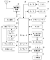
- FIG. 2 is an illustrative view showing an electrical configuration of the mobile phone shown in FIG.
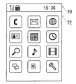
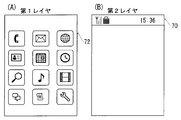
- FIG. 3 is an illustrative view showing one example of a standby screen displayed on the display shown in FIG. 4 is an illustrative view showing an example of a layer structure of an image displayed on the display shown in FIG. 1, FIG. 4 (A) shows a first layer, and FIG. 4 (B) shows a second layer.
- FIG. 5 is an illustrative view showing one example of display of an image in which brightness and image parameters are adjusted by a CABC (Content Adaptive Brightness Control) function of the display driver shown in FIG.
- CABC Content Adaptive Brightness Control
- FIG. 6 is an illustrative view showing another example of the layer structure of the image displayed on the display shown in FIG. 1, FIG. 6 (A) shows the first layer, and FIG. 6 (B) shows the second layer. .
- FIG. 7 is an illustrative view showing one example of composite image data in which the images of the respective layers shown in FIG. 6 are combined.
- FIG. 8 is an illustrative view showing another example of display of an image whose luminance and image parameters are adjusted by the CABC function of the display driver shown in FIG.
- FIG. 9 is an illustrative view showing one example of an application screen displayed on the display shown in FIG. 10 is an illustrative view showing another example of the layer structure of the image displayed on the display shown in FIG. 1, FIG.
- FIG. 10 (A) shows the first layer
- FIG. 10 (B) shows the second layer.
- FIG. 11 is an illustrative view showing one example of composite image data in which the images of the respective layers shown in FIG. 10 are combined.
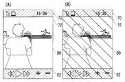
- FIG. 12 is an illustrative view showing another example of display of an image whose luminance and image parameters are adjusted by the CABC function of the display driver shown in FIG. 13 is an illustrative view showing still another example of display of an image whose luminance and image parameters are adjusted by the CABC function of the display driver shown in FIG. 1, and
- FIG. 13A is image data input to the display driver.
- FIG. 13B shows an example of an image displayed on the display.
- FIG. 14 is an illustrative view showing one example of a memory map of the RAM shown in FIG.
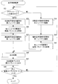
- FIG. 15 is a flowchart showing an example of the power saving control process of the processor shown in FIG.
- FIG. 16 is a flowchart showing an example of display control processing of the processor shown in FIG.
- a mobile phone 10 is a smartphone as an example, and includes a vertically long flat rectangular housing 12.
- the present invention can be applied to any portable terminal such as a tablet terminal or a PDA.
- the main surface (front surface) of the housing 12 is provided with a display 14 such as a liquid crystal functioning as a display unit.
- a touch panel 16 is provided on the display 14. Therefore, in the cellular phone 10 of this embodiment, most of the input operations except those by hard key operations described later are performed through the touch panel 16.
- a speaker 18 is built in the main surface side of one end of the housing 12 in the vertical direction, and a microphone 20 is built in the main surface side of the other end in the vertical direction.
- the main surface of the housing 12 is provided with a call key 22a, an end key 22b, and a menu key 22c as hard keys constituting input operation means together with the touch panel 16 in this embodiment.
- the user can input a telephone number by touching the dial key displayed on the display 14 with the touch panel 16, and can start a voice call by operating the call key 22a.
- the user can end the voice call by operating the call end key 22b.
- the user can turn on / off the power of the mobile phone 10 by pressing and holding the end call key 22b.
- a menu screen is displayed on the display 14, and a desired operation can be performed by touching the touch panel 16 with respect to the soft keys and menu icons displayed on the display 14 in that state.
- the function can be executed.
- the mobile phone 10 of the embodiment shown in FIG. 1 includes a processor 30 called a computer or a CPU.
- the processor 30 is connected to a wireless communication circuit 32, an A / D converter 36, a D / A converter 38, an input device 40, a display driver 42, a flash memory 50, a RAM 52, a touch panel control circuit 54, a power supply circuit 56, and the like.
- the wireless communication circuit 32 is connected to a wireless communication circuit 32, an A / D converter 36, a D / A converter 38, an input device 40, a display driver 42, a flash memory 50, a RAM 52, a touch panel control circuit 54, a power supply circuit 56, and the like.
- the processor 30 manages the overall control of the mobile phone 10.
- the RAM 52 functioning as a storage unit, all or a part of a program preset in the flash memory 50 is expanded when used, and the processor 30 operates according to the program on the RAM 52.
- the RAM 52 is further used as a working area or a buffer area for the processor 30.
- the processor 30 includes a GUP core 30a for generating 2D or 3D images and a video core (sometimes referred to as a codec core) 30b for decoding and encoding moving images.
- the GPU core 30a operates when an application using a GUI image or the like is executed.
- the video core 30b operates when an application for reproducing a moving image is executed.
- the GPU core 30a and the video core 30b may be connected to the processor 30 as independent ICs.
- the input device 40 includes hard keys 22a-22c shown in FIG. 1, and constitutes an operation unit or an input unit. Information on the hard key operated by the user (key data) is input to the processor 30.
- the wireless communication circuit 32 is a circuit for transmitting and receiving radio waves for voice calls and mails through the antenna 34.
- the wireless communication circuit 32 is a circuit for performing wireless communication by the CDMA method. For example, when the user operates the input device 40 to instruct a telephone call (calling), the wireless communication circuit 32 performs a telephone call processing under the instruction of the processor 30 and sends a telephone call signal via the antenna 34. Output. The telephone call signal is transmitted to the other party's telephone through the base station and the communication network. When an incoming call process is performed at the other party's telephone, a communicable state is established, and the processor 30 executes a call process.
- the microphone 20 shown in FIG. 1 is connected to the A / D converter 36.
- the audio signal from the microphone 20 is input to the processor 30 as digital audio data through the A / D converter 36.
- the speaker 18 is connected to the D / A converter 38.
- the D / A converter 38 converts digital audio data into an audio signal and supplies the audio signal to the speaker 18 through an amplifier. Therefore, the sound data is output from the speaker 18.
- the sound collected by the microphone 20 is transmitted to the other party's telephone, and the sound collected by the other party's telephone is output from the speaker 18.
- the LED driver 44 is connected to an LED 46 that functions as a backlight of the display 14.
- the display 14 displays a moving image or a still image according to the still image data generated by the GPU core 30a or the moving image data generated by the video core 30b. That is, the display driver 42 controls display on the display 14 connected to the display driver 42 under the instruction of the processor 30.
- the display driver 42 includes a video memory that temporarily stores image data to be displayed.
- the display 14 is provided with a backlight having the LED 46 as a light source.
- the display driver 42 controls the LED driver 44 to adjust the luminance of the LED 46 (display 14) based on the output of the illuminance sensor 48, and controls the lighting / extinguishing of the LED 46 in accordance with a command from the processor 30.
- the display driver 42 of the present embodiment has a CABC (Content Adaptive Brightness Control) function that reduces the power consumption of the mobile phone 10 by adjusting the brightness of the LED 46 based on the input image data.
- CABC Content Adaptive Brightness Control
- the CABC function is enabled, the brightness, contrast, gamma value, saturation, and the like of the image data are corrected so as not to make the user aware of changes in screen brightness.
- the image parameters of the displayed image are corrected, the image quality slightly changes with respect to the original image.
- the display driver 42 may be called an adjustment unit.
- image parameters of this embodiment include image brightness (brightness), contrast, gamma value, saturation, and the like.
- the touch panel 16 shown in FIG. 1 is connected to the touch panel control circuit 54.
- the touch panel control circuit 54 applies necessary voltage and the like to the touch panel 16 and also provides the processor 30 with a touch start signal indicating the start of touch by the user, an end signal indicating the end of touch by the user, and coordinate data indicating the touch position. input. Therefore, the processor 30 can determine which icon or key the user has touched based on the coordinate data.
- the touch panel 16 is a capacitive touch panel that detects a change in electrostatic capacitance that occurs between the surface and an object such as a finger that approaches the surface.
- the touch panel 16 detects that one or more fingers touched the touch panel 16, for example. Therefore, the touch panel 16 is also called a pointing device.
- the touch panel control circuit 54 functions as a detection unit, detects a touch operation within the effective touch range of the touch panel 16, and outputs coordinate data indicating the position of the touch operation to the processor 30. That is, the user inputs an operation position, an operation direction, and the like to the mobile phone 10 by performing a touch operation on the surface of the touch panel 16.
- the touch operation of this embodiment includes a tap operation, a long tap operation, a flick operation, a slide operation, and the like.
- the power circuit 56 is a power management IC, and the power circuit 56 supplies power based on the voltage of the secondary battery 58 to the entire system.
- a state in which the power supply circuit 56 supplies power to the entire system is referred to as a power-on state.
- a state in which the power supply circuit 56 is not supplying power to the entire system is referred to as a power-off state.
- the power supply circuit 56 is activated when a power-on operation is performed by the input device 40 in the power-off state, and is stopped when a power-off operation is performed by the input device 40 in the power-on state.
- the power supply circuit 56 is activated when an external power supply is connected to an external power supply connector (not shown) and power is supplied (charged) to the secondary battery 58, and the secondary battery 58 is fully charged. Stops when a state of charge is detected. “Charging” means that the external power supply connector is connected to the external power supply, receives power supply from the external power supply, and the secondary battery 58 stores electric energy.
- FIG. 3 is an illustrative view showing the display 14 displaying a standby screen.
- display 14 includes a state display area 70 and a function display area 72.
- state display area 70 an icon (pict) indicating a radio wave reception state by antenna 34, a remaining battery level of secondary battery 58 is provided. Icon and date and time are displayed.
- function display area 72 a standby screen is displayed. On this standby screen, menu icons for executing applications and changing the settings of the mobile phone 10 are displayed.
- the image displayed on display 14 is displayed using a plurality of layers.
- the standby screen is displayed by overlapping two layers (first layer and second layer), and in the virtual space, the first layer is provided on the viewpoint side (user side), and the direction away from the viewpoint
- the second layer is arranged in
- a menu icon displayed on the function display area 72 that is, the standby screen is drawn.
- a state display area 70 that is, an icon indicating the radio wave reception state, an icon indicating the remaining battery level of the secondary battery, and the date and time are drawn.
- the processor 30 combines the images drawn on the first layer and the second layer, and outputs the combined image data to the display driver 42. Thereby, the standby screen shown in FIG. 3 is displayed.
- the power saving mode is set when the remaining battery level of the secondary battery 58 becomes the first threshold value or less.
- the CABC function of the display driver 42 is enabled.
- the standby screen shown in FIG. 5 is displayed when the CABC function is valid, and the image quality is slightly changed from the standby screen shown in FIG. In FIG. 5, hatching is given to the entire display for easy understanding of the change in image quality, but the actual display is not hatched.
- the displayed image (output to the display driver 42) so that the power saving reduced by the CABC function is increased. Image parameter) is changed in advance.
- the brightness of the LED 46 decreases as the displayed image becomes darker (closer to black), and the brightness of the LED 46 increases as the displayed image becomes brighter (closer to white). Therefore, when the remaining battery level of the secondary battery 58 becomes equal to or less than the second threshold value, the image parameter is changed to darken the displayed image in order to further reduce the power consumption of the LED 46.
- the processor 30 darkens the displayed image by reducing the brightness of the image, increasing the contrast and gamma values, and decreasing the saturation.
- the image parameters of the images drawn on the first layer and the second layer are lowered. That is, the image parameter is changed so that each icon drawn in the status display area 70 and its background and each menu icon drawn in the function display area 72 are darkened. Then, combined image data corresponding to FIG. 7 obtained by combining the images drawn on the first layer and the second layer is output to the display driver 42. As a result, the image shown in FIG. 8 is displayed on the display 14. Thus, by reducing the image parameters of all the images displayed on the screen, the power consumption can be further reduced.
- the image parameters of the image of the web page of the first layer drawn in the function display area 72 by the application of the browser are not changed. Therefore, when the images drawn on the first layer and the second layer are combined, the combined image data shown in FIG. 11 is output to the display driver 42. That is, the image parameter of the application can be prevented from being changed.
- the display 14 displays an image corrected by the CABC function of the display driver 42, that is, the image shown in FIG.
- the application image is an image drawn by executing the application.
- the application image includes a GUI, characters, icons, and the like.
- the brightness of the LED (backlight) 46 is adjusted to be low by the CABC function. Therefore, the power consumption of the LED 46 is reduced. Further, by using layers, it is possible to easily separate an image whose image parameter is changed from an image whose image parameter is not changed.
- image parameters may not be changed only for content images such as videos or photographs.
- a playback application that displays (plays back) a content image is executed will be described.
- the function display area 72 is divided into a moving image display area 80 and a GUI display area 82.
- a content image reproduced using the video core 30b is displayed in the moving image display area 80, and a GUI generated using the GPU core 30a is displayed in the GUI display area 82.
- the icon of the status display area 70 and the GUI displayed in the GUI display area 82 are drawn on the second layer, and the content image played back by the playback application is drawn on the first layer. The That is, only the content image reproduced using the video core 30b is drawn on the first layer, and the other images are drawn on the second layer.
- the processor 30 changes the image parameter of the icon and GUI drawn on the second layer and does not change the image parameter of the content image drawn on the first layer.
- composite image data as shown in FIG. 13A is created, and when this composite image data is output to the display driver 42, the image shown in FIG. The
- the content image may be drawn on a dedicated layer.
- the icon of the status display area 70 is drawn on the first layer, and the GUI displayed on the GUI display area 82 is drawn on the second layer.
- an image displayed using three or more layers may be synthesized.
- the content image may be displayed on the display 14 by a browser application, a television application, a preview application, a camera application, or the like.
- a program storage area 302 and a data storage area 304 are formed in the RAM 52 shown in FIG.
- the program storage area 302 is an area for reading and storing (developing) part or all of the program data set in advance in the flash memory 50 (FIG. 2).
- the program storage area 302 includes a power saving control program 310 for setting and canceling the power saving mode based on the remaining battery level, a display control program 312 for controlling an image output to the display driver 42, and the like.
- the program storage area 302 includes a program for executing each application.
- the data storage area 304 of the RAM 52 is provided with a battery remaining amount buffer 330, a layer buffer 332, a composite image buffer 334, and the like, as well as a first power saving flag 336, a second power saving flag 338, a CABC flag 340, and the like. Is provided.
- the battery remaining capacity buffer 330 data indicating the remaining battery capacity of the secondary battery 58 output from the power supply circuit 56 is temporarily stored.
- the layer buffer 332 temporarily stores image data drawn on the first layer and the second layer.
- the composite image buffer 334 temporarily stores composite image data obtained by combining the images of the layers.
- the first power saving flag 336 is a flag indicating that the remaining battery level is equal to or less than the first threshold and greater than the second threshold.
- the first power saving flag 336 is composed of a 1-bit register. When the first power saving flag 336 is turned on (established), a data value “1” is set in the register. On the other hand, when the first power saving flag 336 is turned off (not established), a data value “0” is set in the register.
- the second power saving flag 338 is a flag indicating that the remaining battery level is equal to or less than the second threshold value.
- the CABC flag 340 is a flag indicating whether the CABC function of the display driver 42 is valid. For example, when the first power saving flag 336 is turned on, the processor 30 issues a command for enabling the CABC function to the display driver 42 and turns on the CABC flag 340. Note that the second power saving flag 338 and the CABC flag 340 have substantially the same configuration as the first power saving flag 336, and thus description of the configuration of these flags is omitted.
- the data storage area 304 stores image data and the like displayed on the standby screen, and is provided with counters and flags necessary for the operation of the mobile phone 10.
- the processor 30 includes a Linux (registered trademark) -based OS such as Android (registered trademark) and REX, and the power saving control process illustrated in FIG. 15 and the display control process illustrated in FIG. 16 under the control of the other OS. Process multiple tasks in parallel.
- Linux registered trademark
- REX Registered trademark
- step S1 the processor 30 acquires the remaining battery level. That is, a value indicating the remaining battery level of the secondary battery 58 is acquired from the power supply circuit 56 and stored in the remaining battery level buffer 330. Subsequently, in step S3, the processor 30 determines whether or not it is equal to or less than the first threshold value. That is, it is determined whether to set the power saving mode. If “NO” in the step S3, that is, if the remaining battery level of the secondary battery 58 is larger than the first threshold value, the processor 30 turns off the CABC flag 340 in a step S5, and the first power saving flag in a step S7. 336 and the second power saving flag 338 are turned off. That is, the CABC function of the display driver 42 is disabled and the power saving mode is released. Then, when the process of step S7 ends, the processor 30 returns to the process of step S1.
- the processor 30 turns on the CABC flag 340 in a step S9. That is, the CABC function of the display driver 42 is validated.
- step S11 the processor 30 determines whether or not it is equal to or less than the second threshold value. That is, it is determined whether the image parameter of the displayed image needs to be changed. If “NO” in the step S11, that is, if the remaining battery level of the secondary battery 58 is equal to or smaller than the first threshold value and larger than the second threshold value, the processor 30 in the step S13, the first power saving flag 336. Turn on. On the other hand, if “YES” in the step S11, that is, if the remaining battery level of the secondary battery 58 is equal to or less than the first threshold value, the processor 30 turns on the second power saving flag 338 in a step S15.
- step S13 or step S15 ends, the processor 30 returns to the process of step S1.
- FIG. 16 is a flowchart of the display control process.
- the display control process is started when the second power saving flag 338 is turned on.
- the processor 30 determines whether or not the application is being executed.
- step S31 the processor 30 draws the image of the state display area 70 on the second layer in a step S33.
- a step S33 For example, as shown in FIG. 9, an icon (pictogram) indicating a radio wave reception state by the antenna 34, an icon indicating the remaining battery level of the secondary battery, and the date and time are drawn on the second layer.
- step S35 the processor 30 changes the image parameter of the image of the second layer. That is, the image parameter is changed so that the image drawn on the second layer becomes dark.
- the image drawn in the second parameter changes, for example, from the state shown in FIG. 9 to the state shown in FIG.
- the processor 30 that executes the process of step S35 functions as a first changing unit.
- step S37 the processor 30 draws the image of the function display area 72 on the first layer. For example, as shown in FIG. 10A, the image of the application is drawn on the first layer. And if the process of step S37 is complete
- step S31 the image of the state display area 70 is drawn on the second layer. For example, as shown in FIG. 4B, icons and the like are drawn on the second layer.
- step S41 the processor 30 draws the image of the function display area 72 on the first layer. For example, as shown in FIG. 4A, menu icons and the like are drawn on the first layer.
- step S43 the processor 30 changes the image parameter of the image of each layer. That is, the image parameter is changed so that the images drawn on the first layer and the second layer become dark. As a result, for example, the images shown in FIGS. 4 (A) and 4 (B) change to the states shown in FIGS. 6 (A) and 6 (B).
- processor 30 that executes the process of step S43 functions as a second changing unit. Further, the processor 30 that executes the processes of steps S35 and S43 functions as a changing unit. In addition, the processor 30 that executes the processes of step S33 and step S39 functions as a first drawing unit. Further, the processor 30 that executes the processes of steps S37 and S41 functions as a second drawing unit.
- step S45 the processor 30 executes a synthesis process. That is, the images drawn on the first layer and the second layer are combined, and the combined image data is stored in the combined image buffer 334.
- the processor 30 that executes the process of step S45 functions as a synthesis unit.
- the processor 30 outputs the composite image data to the display driver 42 in step S47. That is, the image data stored in the composite image buffer 334 is input to the display driver 42. Then, the display driver 42 adjusts the luminance of the LED 46 based on the input image data, and adjusts the image parameter of the composite image data. As a result, for example, the images shown in FIGS. 8, 12, and 13 (B) are displayed on the display 14.
- step S49 the processor 30 determines whether or not the second power saving flag 338 is turned off. For example, it is determined whether or not the remaining battery level of the secondary battery 58 is greater than the second threshold value. If “NO” in the step S49, that is, if the remaining battery level of the secondary battery 58 is equal to or less than the second threshold value, the processor 30 returns to the process of the step S31.
- the processor 30 ends the display control process.
- step S31 the processor 30 may determine whether an application for displaying a content image is being executed. If the application for displaying the content image is not executed, the processes of steps S39 to S43 are executed. On the other hand, if an application for displaying a content image is being executed, the processor 30 draws an icon, a GUI, or the like on the first layer or the second layer in step S33. In step S35, the processor 30 changes image parameters such as an icon and a GUI. In step S37, the processor 30 draws the content image on the specific layer. Thereby, it is possible to prevent the image parameter of the content image such as the video or the photograph from being changed.
- a process for correcting a color tone composed of saturation and brightness among image parameters may be added to the displayed image.
- a displayed image is darkened by a two-gradation (monochrome) process in which a threshold is set so that the number of black images increases, or an inversion process that inverts the saturation and lightness gradations.
- a color tone correction process combining these processes may be added to the displayed image.
- the LED 46 is used as the backlight of the display 14, but in other embodiments, other light sources such as a cold cathode tube may be used.
- the display driver 42 adjusts the luminance of the organic EL panel because the organic EL panel is not provided with a backlight. That is, when the CABC function is enabled, the luminance of the organic EL panel is adjusted by the display driver 42.
- the power saving mode may be always set regardless of the remaining battery level of the secondary battery 58. Further, the second power saving flag 338 may be always turned on. And the user may be able to arbitrarily change the settings related to the power saving mode.
- the program used in this embodiment may be stored in the HDD of the data distribution server and distributed to the mobile phone 10 via the network.
- the storage medium may be sold or distributed in a state where a plurality of programs are stored in a storage medium such as an optical disk such as a CD, DVD, or BD, a USB memory, or a memory card.
- the display unit, the backlight provided in the display unit, the adjustment unit that adjusts the luminance of the backlight based on the image displayed on the display unit, and the adjustment unit are operating.
- the portable terminal includes a changing unit that changes an image parameter so as to darken an image displayed on the display unit.
- the mobile terminal ( reference numeral exemplifying a corresponding part in the embodiment; the same applies hereinafter) includes a display unit (14) provided with a backlight (46) having an LED as a light source.
- the adjustment unit (42) has a CABC function, for example, and adjusts the brightness of the backlight and the image quality of the image to be displayed based on the image displayed on the display unit.
- the changing unit (30, S35, S43) changes the image parameter so as to darken the image displayed on the display unit.
- the adjustment unit adjusts the backlight brightness to be low. Therefore, the power consumption of the backlight is reduced.
- the first drawing unit for drawing a part of the image displayed on the display unit on the first layer, and the other part of the image displayed on the display unit on the second layer.
- the image forming apparatus further includes a second drawing unit for drawing, and a combining unit for combining images drawn on the first layer and the second layer as images to be displayed on the display unit, and the changing unit is an image drawn on the second layer.
- a first changing unit for changing the image parameter so as to darken the image.
- the first drawing unit (30, S33, S39) draws, for example, a menu icon image displayed on the standby screen on the first layer.
- the second drawing unit (30, S37, S41) draws the remaining battery level of the secondary battery displayed on the standby screen, an icon indicating the reception state of the antenna, and the like on the second layer.
- the combining unit (30, S45) combines the images drawn on the first layer and the second layer as images to be displayed on the display unit. Then, the first changing unit (30, S35) changes the image parameter so as to darken the icon image drawn on the second layer, for example.
- the layer by using the layer, it is possible to easily separate an image whose image parameter is changed from an image whose image parameter is not changed.
- the first changing unit changes the image parameter so as to darken the image drawn on the second layer when the image is drawn on the first layer by the application.
- the first change unit displays an icon indicating the remaining battery level drawn on the second layer.
- the image parameter is changed so that the image is darkened.
- the image parameter of the application can be prevented from being changed.
- the first drawing unit for drawing a part of the image displayed on the display unit on the first layer, and the other part of the image displayed on the display unit on the second layer.
- the image forming apparatus further includes a second drawing unit for drawing, and a combining unit for combining the images drawn on the first layer and the second layer as images to be displayed on the display unit, and the changing unit includes the first layer and the second layer.
- a second changing unit for changing the image parameter of each drawn image is included.
- the fourth mode similarly to the second mode, images are drawn on the first layer and the second layer, respectively, and these images are combined by the combining unit.
- the second changing unit (30, S43) changes the image parameters of the images drawn on the first layer and the second layer, respectively.
- the power consumption can be further reduced by lowering the image parameters of all the images displayed on the screen.
- the image parameter includes at least one of brightness, contrast, gamma value, and saturation.
- the sixth aspect of the above-described embodiment includes a display unit (14), a backlight (46) provided in the display unit, and an adjustment unit (42) that adjusts the luminance of the backlight based on the image displayed on the display unit.
- a display control method for a mobile terminal (10), wherein the processor of the mobile terminal changes an image parameter so as to darken an image displayed on the display unit when the adjustment unit is operating This is a display control method for executing (S35, S43).
- the power consumption of the backlight can be reduced as in the first aspect.
Landscapes
- Engineering & Computer Science (AREA)
- Theoretical Computer Science (AREA)
- General Physics & Mathematics (AREA)
- Physics & Mathematics (AREA)
- Signal Processing (AREA)
- General Engineering & Computer Science (AREA)
- Computer Networks & Wireless Communication (AREA)
- Human Computer Interaction (AREA)
- Computer Hardware Design (AREA)
- Telephone Function (AREA)
- Control Of Indicators Other Than Cathode Ray Tubes (AREA)
- Power Sources (AREA)
- Liquid Crystal Display Device Control (AREA)
Abstract
携帯電話機10は、バックライトとして機能するLED(46)が設けられたディスプレイ14および表示ドライバ(42)などを備える。表示ドライバは、ディスプレイ14に表示される画像に基づいてバックライトの輝度および表示する画像の画質などを調整するCABC(Content Adaptive Brightness Control)機能を有する。たとえば、二次電池(58)の電池残量が第1閾値以下となるとCABC機能が有効な状態になる。また、電池残量が第2閾値以下となると、表示ドライバに出力される画像が暗くなるように、明るさ、コントラスト、ガンマ値および彩度などの画像パラメータが変更される。
Description
この発明は、携帯端末および表示制御方法に関し、特にディスプレイを有する、携帯端末および表示制御方法に関する。
或る液晶表示装置では、液晶表示装置に表示される映像の画像解析が行われる。この解析結果に基づいて、液晶表示装置のバックライトの制御によってバックライトの輝度を低下させることで、消費電力を低減することが出来る。また、併せて、液晶表示素子の制御によって画像調整を行うことで、高品位で高画質な映像を表示することが出来る。
ところが、明るい画像が表示された場合、バックライトの輝度があまり低下しないため、バックライトの消費電力があまり削減されない。
それゆえに、この発明の主たる目的は、新規な、携帯端末および表示制御方法を提供することである。
この発明の他の目的は、消費電力を削減することが出来る、携帯端末および表示制御方法を提供することである。
上記の課題を解決するための携帯端末は、表示部、表示部に設けられるバックライト、表示部に表示される画像に基づいてバックライトの輝度を調整する調整部、調整部が動作しているとき、表示部に表示される画像を暗くするように画像パラメータを変更する変更部を備える。
上記の課題を解決するための表示制御方法は、表示部、表示部に設けられるバックライトおよび表示部に表示される画像に基づいてバックライトの輝度を調整する調整部を有する、携帯端末における表示制御方法であって、携帯端末のプロセッサが、調整部が動作しているとき、表示部に表示される画像を暗くするように画像パラメータを変更する変更ステップを実行する。
この発明によれば、消費電力を削減することが出来る。
この発明の上述の目的、その他の目的、特徴および利点は、図面を参照して行う以下の実施例の詳細な説明から一層明らかとなろう。
図1を参照して、この発明の一実施例の携帯電話機10は、一例としてスマートフォン(smart phone)であり、縦長の扁平矩形のハウジング12を含む。ただし、この発明は、タブレット端末、PDAなど任意の携帯端末に適用可能であることを予め指摘しておく。
ハウジング12の主面(表面)には、表示部として機能する、たとえば液晶などのディスプレイ14が設けられる。ディスプレイ14の上には、タッチパネル16が設けられる。したがって、この実施例の携帯電話機10では、後述のハードキーの操作によるものを除く大部分の入力操作は、このタッチパネル16を介して行われる。
ハウジング12の縦方向一端の主面側にスピーカ18が内蔵され、縦方向他端の主面側にマイク20が内蔵される。
ハウジング12の主面には、タッチパネル16と共に入力操作手段を構成するハードキーとして、この実施例では、通話キー22a、終話キー22bおよびメニューキー22cが設けられる。
たとえば、ユーザは、ディスプレイ14に表示されたダイヤルキーに対して、タッチパネル16によってタッチ操作を行うことで電話番号を入力でき、通話キー22aを操作して音声通話を開始することが出来る。ユーザは終話キー22bを操作すれば、音声通話を終了することが出来る。なお、ユーザは、終話キー22bを長押しすることによって、携帯電話機10の電源をオン/オフすることが出来る。
また、メニューキー22cを操作すれば、ディスプレイ14にメニュー画面が表示され、その状態でディスプレイ14に表示されているソフトキーやメニューアイコンなどに対して、タッチパネル16によるタッチ操作を行うことによって所望の機能を実行することが出来る。
図2を参照して、図1に示す実施例の携帯電話機10は、コンピュータまたはCPUと呼ばれるプロセッサ30などを含む。プロセッサ30には、無線通信回路32、A/D変換器36、D/A変換器38、入力装置40、表示ドライバ42、フラッシュメモリ50、RAM52、タッチパネル制御回路54および電源回路56などが接続される。
プロセッサ30は、携帯電話機10の全体制御を司る。記憶部として機能するRAM52には、フラッシュメモリ50に予め設定されているプログラムの全部または一部が使用に際して展開され、プロセッサ30はこのRAM52上のプログラムに従って動作する。なお、RAM52はさらに、プロセッサ30のワーキング領域ないしバッファ領域として用いられる。
また、プロセッサ30には、2Dまたは3D画像を生成するためのGUPコア30aおよび動画像をデコードおよびエンコードするためビデオコア(コーデックコアと言うこともある)30bが含まれている。たとえば、GPUコア30aは、GUIの画像などを利用するアプリケーションが実行されたときに動作する。ビデオコア30bは、動画像を再生するアプリケーションが実行されたときに動作する。ただし、他の実施例では、GPUコア30aおよびビデオコア30bは、それぞれ独立したICとしてプロセッサ30に接続されてもよい。
入力装置40は、図1に示す、ハードキー22a-22cを含むものであり、操作部または入力部を構成する。ユーザが操作したハードキーの情報(キーデータ)はプロセッサ30に入力される。
無線通信回路32は、アンテナ34を通して、音声通話やメールなどのための電波を送受信するための回路である。実施例では、無線通信回路32は、CDMA方式での無線通信を行うための回路である。たとえば、ユーザが入力装置40を操作して電話発信(発呼)を指示すると、無線通信回路32は、プロセッサ30の指示の下、電話発信処理を実行し、アンテナ34を介して電話発信信号を出力する。電話発信信号は、基地局および通信網を経て相手の電話機に送信される。そして、相手の電話機において着信処理が行われると、通信可能状態が確立され、プロセッサ30は通話処理を実行する。
A/D変換器36には図1に示すマイク20が接続される。マイク20からの音声信号はこのA/D変換器36を通してディジタルの音声データとしてプロセッサ30に入力される。一方、D/A変換器38にはスピーカ18が接続される。D/A変換器38は、ディジタルの音声データを音声信号に変換して、アンプを介してスピーカ18に与える。したがって、音声データの音声がスピーカ18から出力される。そして、通話処理が実行されている状態では、マイク20によって集音された音声が相手の電話機に送信され、相手の電話機で集音された音声が、スピーカ18から出力される。
表示ドライバ42には、図1に示すディスプレイ14、LEDドライバ44および照度センサ48が接続される。また、LEDドライバ44には、ディスプレイ14のバックライトとして機能するLED46が接続される。
ディスプレイ14は、GPUコア30aによって生成された静止画像データまたはビデオコア30bによって生成された動画像データに従って、動画像または静止画像を表示する。つまり、表示ドライバ42は、プロセッサ30の指示の下、当該表示ドライバ42に接続されたディスプレイ14の表示を制御する。また、表示ドライバ42は表示する画像データを一時的に記憶するビデオメモリを含む。
ディスプレイ14には、上述した通りLED46などを光源とするバックライトが設けられている。表示ドライバ42はLEDドライバ44を制御することで、照度センサ48の出力に基づいてLED46(ディスプレイ14)の輝度を調整し、プロセッサ30の命令に従ってLED46の点灯/消灯を制御する。
また、本実施例の表示ドライバ42は、入力された画像データに基づいて、LED46の輝度を調整することで、携帯電話機10の消費電力を抑えるCABC(Content Adaptive Brightness Control)機能を備えている。また、CABC機能が有効にされている場合、画面の明るさの変化をユーザに意識させないようにするため、画像データの明るさ、コントラスト、ガンマ値および彩度などが補正される。そして、表示されている画像の画像パラメータが補正されると、元の画像に対して画質が若干変化する。
このようにして、LED46(バックライト)の輝度が調整されるため、表示ドライバ42は調整部と呼ばれることもある。なお、本実施例の画像パラメータには、画像の明るさ(明度)、コントラスト、ガンマ値、彩度などが含まれる。
タッチパネル制御回路54には、図1に示すタッチパネル16が接続される。タッチパネル制御回路54は、タッチパネル16に必要な電圧などを付与するとともに、ユーザによるタッチの開始を示すタッチ開始信号、ユーザによるタッチの終了を示す終了信号、およびタッチ位置を示す座標データをプロセッサ30に入力する。したがって、プロセッサ30はこの座標データに基づいて、ユーザが、どのアイコンやキーにタッチしたかを判断することができる。
実施例では、タッチパネル16は、その表面と表面に接近した指などの物体との間に生じる静電容量の変化を検出する静電容量方式のタッチパネルである。タッチパネル16は、たとえば1本または複数本の指がタッチパネル16に触れたことを検出する。そのため、タッチパネル16はポインティングデバイスとも呼ばれる。タッチパネル制御回路54は検出部として機能し、タッチパネル16のタッチ有効範囲内でのタッチ操作を検出して、そのタッチ操作の位置を示す座標データをプロセッサ30に出力する。つまり、ユーザは、タッチパネル16の表面に対してタッチ操作を行うことによって、操作位置や、操作方向などを携帯電話機10に入力する。なお、本実施例のタッチ操作には、タップ操作、ロングタップ操作、フリック操作、スライド操作などが含まれる。
電源回路56は電源管理用のICであり、電源回路56は二次電池58の電圧に基づく電源をシステム全体に供給する。ここで、電源回路56が電源をシステム全体に供給している状態を、電源オン状態と言うことにする。一方、電源回路56が電源をシステム全体に供給していない状態を、電源オフ状態と言うことにする。電源回路56は、電源オフ状態で、入力装置40によって電源オン操作がされると起動され、電源オン状態で、入力装置40によって電源オフ操作がされると停止される。さらに、電源オフ状態であっても、電源回路56は、図示しない外部電源コネクタに外部電源が接続され、二次電池58に電力が供給(充電)されると起動し、二次電池58の満充電状態が検出されると停止する。また、「充電」とは、外部電源コネクタが外部電源と接続され外部電源から電力の供給を受け、二次電池58が電気エネルギーを蓄えることを言う。
図3は待機画面を表示するディスプレイ14を示す図解図である。図3を参照して、ディスプレイ14は状態表示領域70および機能表示領域72を含み、状態表示領域70には、アンテナ34による電波受信状態を示すアイコン(ピクト)、二次電池58の電池残量を示すアイコンおよび日時が表示される。機能表示領域72には待機画面が表示されている。この待機画面には、アプリケーションを実行したり、携帯電話機10の設定を変更したりするためのメニューアイコンが表示される。
図4を参照して、ディスプレイ14に表示される画像は複数のレイヤを利用して表示されている。たとえば、待機画面は、2つのレイヤ(第1レイヤ、第2レイヤ)を重ねることで表示されており、仮想空間において、視点側(使用者側)に第1レイヤが設けられ、視点から離れる方向に第2レイヤが配置される。図4(A)に示す第1レイヤには、機能表示領域72、つまり待機画面で表示されるメニューアイコンが描画される。一方、図4(B)に示す第2レイヤには、状態表示領域70、つまり電波受信状態を示すアイコン、二次電池の電池残量を示すアイコンおよび日時が描画される。そして、プロセッサ30は、第1レイヤおよび第2レイヤに描画された画像を合成し、合成画像データを表示ドライバ42に出力する。これにより、図3に示す待機画面が表示される。
ここで、本実施例では、二次電池58の電池残量が第1閾値以下になると省電力モードが設定される。そして、省電力モードが設定されると、表示ドライバ42のCABC機能が有効にされる。たとえば、図5に示す待機画面は、CABC機能が有効なときに表示されているものであり、図3に示す待機画面に対して、画質が若干変化している。なお、図5では、画質の変化を分かりやすくするために、表示の全体に斜線を付与しているが、実際の表示に斜線が付されることはない。
そして、二次電池58の電池残量が、第1閾値よりも小さい第2閾値以下になると、CABC機能によって削減される省電力が多くなるように、表示される画像(表示ドライバ42に出力される画像)の画像パラメータが、事前に変更される。
CABC機能では、表示される画像が暗いほど(黒に近いほど)LED46の輝度が低くなり、表示される画像が明るいほど(白に近いほど)LED46の輝度が高くなる。そのため、二次電池58の電池残量が第2閾値以下になると、LED46の消費電力をさらに削減するために、表示される画像を暗くするように画像パラメータが変更される。本実施例では、プロセッサ30は、画像の明るさを下げ、コントラストおよびガンマ値を高くし、彩度を下げることで、表示される画像を暗くする。
図6(A),(B)を参照して、電池残量が第2閾値以下となると、第1レイヤおよび第2レイヤのそれぞれに描画された画像の画像パラメータが低くされる。つまり、状態表示領域70に描画される各アイコンおよびその背景と、機能表示領域72に描画される各メニューアイコンが暗くなるように、画像パラメータが変更される。そして、第1レイヤおよび第2レイヤに描画された画像を合成することで得らえた図7に対応する合成画像データが、表示ドライバ42に出力される。その結果、ディスプレイ14には、図8に示す画像が表示される。このように、画面に表示される全ての画像の画像パラメータを低くすることで、消費電力をより削減することが出来る。
次に、アプリケーションが実行されている状態について説明する。図9を参照して、たとえばブラウザのアプリケーションが実行されると機能表示領域72には、ブラウザのアプリケーションによって取得されたウェブページが表示される。この状態で、電池残量が第2閾値以下となると、図10(B)に示すように、第2レイヤに描画される状態表示領域70の画像の画像パラメータが変更される。
ただし、図10(A)に示すように、ブラウザのアプリケーションによって機能表示領域72に描画される、第1レイヤのウェブページの画像の画像パラメータは変更されない。したがって、第1レイヤおよび第2レイヤに描画された画像が合成されると、図11に示す合成画像データが表示ドライバ42に出力される。つまり、アプリケーションの画像は、画像パラメータが変更されないようにすることが出来る。そして、ディスプレイ14には、表示ドライバ42のCABC機能によって補正された画像、つまり図12に示す画像が表示される。なお、アプリケーションの画像とは、アプリケーションが実行されることで描画される画像のことである。そして、アプリケーションの画像には、GUI、文字、アイコンなどが含まれる。
このように、本実施例では、ディスプレイ14に表示される画像が暗くなると、CABC機能よってLED(バックライト)46の輝度が低くなるように調整される。したがって、LED46の消費電力が削減される。また、レイヤを利用することで、画像パラメータを変更する画像と画像パラメータを変更しない画像とを容易に分けることが出来る。
また、他の実施例では、アプリケーションが実行されたときに、映像または写真などのコンテンツ画像だけ、画像パラメータが変更されないようにしてもよい。たとえば、コンテンツ画像を表示(再生)する再生アプリケーションが実行された場合について説明する。図13(A),(B)を参照して、再生アプリケーションが実行されると、機能表示領域72は、動画像表示領域80およびGUI表示領域82に分けられる。動画像表示領域80にはビデオコア30bを利用して再生されたコンテンツ画像が表示され、GUI表示領域82にはGPUコア30aを利用して生成されたGUIなどが表示される。また、各レイヤの図示は省略するが、状態表示領域70のアイコンおよびGUI表示領域82に表示されるGUIが第2レイヤに描画され、再生アプリケーションによって再生されるコンテンツ画像が第1レイヤに描画される。つまり、ビデオコア30bを利用して再生されたコンテンツ画像だけが第1レイヤに描画され、他の画像は第2レイヤに描画される。
そして、プロセッサ30は、第2レイヤに描画されているアイコンおよびGUIの画像パラメータを変更し、第1レイヤに描画されているコンテンツ画像の画像パラメータは変更しないようにする。その結果、図13(A)に示すような、合成画像データが作成され、この合成画像データが表示ドライバ42に出力されると、ディスプレイ14には、図13(B)に示す画像が表示される。
なお、その他の実施例では、コンテンツ画像は、専用レイヤに描画されるようにしてもよい。この場合、状態表示領域70のアイコンが第1レイヤに描画され、GUI表示領域82に表示されるGUIが第2レイヤに描画される。
また、さらにその他の実施例では、3枚以上のレイヤを利用して表示される画像が合成されてもよい。また、コンテンツ画像は、ブラウザアプリケーション、テレビアプリケーション、プレビューアプリケーションおよびカメラアプリケーションなどによってディスプレイ14に表示されてもよい。
以上で実施例の特徴を概説したが、以下には、図14に示すメモリマップおよび図15、図16に示すフロー図を用いて詳細に説明する。
図14を参照して、図2に示すRAM52には、プログラム記憶領域302とデータ記憶領域304とが形成される。プログラム記憶領域302は、先に説明したように、フラッシュメモリ50(図2)に予め設定しているプログラムデータの一部または全部を読み出して記憶(展開)しておくための領域である。
プログラム記憶領域302には、電池残量に基づいて省電力モードを設定および解除する省電力制御プログラム310および表示ドライバ42に出力する画像を制御する表示制御プログラム312などが含まれる。なお、プログラム記憶領域302には、各アプリケーションを実行するためのプログラムなども含まれる。
続いて、RAM52のデータ記憶領域304には、電池残量バッファ330、レイヤバッファ332および合成画像バッファ334などが設けられると共に、第1省電力フラグ336、第2省電力フラグ338およびCABCフラグ340などが設けられる。
電池残量バッファ330には、電源回路56から出力される二次電池58の電池残量を示すデータが一時的に記憶される。レイヤバッファ332には、第1レイヤおよび第2レイヤなどに描画される画像データが一時的に記憶される。合成画像バッファ334には、各レイヤの画像を合成することで得られる合成画像データが一時的に記憶される。
第1省電力フラグ336は、電池残量が第1閾値以下、かつ第2閾値より大きい値であることを示すフラグである。たとえば、第1省電力フラグ336は、1ビットのレジスタで構成される。第1省電力フラグ336がオン(成立)されると、レジスタにはデータ値「1」が設定される。一方、第1省電力フラグ336がオフ(不成立)されると、レジスタにはデータ値「0」が設定される。
第2省電力フラグ338は、電池残量が第2閾値以下であることを示すフラグである。CABCフラグ340は、表示ドライバ42のCABC機能が有効であるかを示すフラグである。たとえば、プロセッサ30は、第1省電力フラグ336がオンになると、表示ドライバ42にCABC機能を有効にする命令を発行すると共に、CABCフラグ340をオンにする。なお、第2省電力フラグ338およびCABCフラグ340は、第1省電力フラグ336と略同じ構成をしているため、これらのフラグの構成の説明は省略する。
なお、データ記憶領域304には、待機画面で表示される画像データなどが記憶されると共に、携帯電話機10の動作に必要なカウンタや、フラグも設けられる。
プロセッサ30は、Android(登録商標)およびREXなどのLinux(登録商標)ベースのOSや、その他のOSの制御下で、図15に示す省電力制御処理、図16に示す表示制御処理などを含む、複数のタスクを並列的に処理する。
図15を参照して、省電力制御処理は、携帯電話機10の電源がオンにされると、開始される。プロセッサ30はステップS1で、電池残量を取得する。つまり、電源回路56から二次電池58の電池残量を示す値を取得し、電池残量バッファ330に記憶する。続いて、ステップS3でプロセッサ30は、第1閾値以下か否かを判断する。つまり、省電力モードを設定するかが判断される。ステップS3で“NO”であれば、つまり二次電池58の電池残量が第1閾値よりも大きければ、プロセッサ30は、ステップS5でCABCフラグ340をオフにし、ステップS7で第1省電力フラグ336および第2省電力フラグ338をオフにする。つまり、表示ドライバ42のCABC機能が無効にされ、省電力モードが解除された状態にされる。そして、ステップS7の処理が終了すれば、プロセッサ30はステップS1の処理に戻る。
一方、ステップS3で“YES”であれば、つまり二次電池58の電池残量が第1閾値以下であれば、ステップS9でプロセッサ30は、CABCフラグ340をオンにする。つまり、表示ドライバ42のCABC機能が有効にされる。
続いて、ステップS11でプロセッサ30は、第2閾値以下か否かを判断する。つまり、表示される画像の画像パラメータを変更する必要があるかが判断される。ステップS11で“NO”であれば、つまり二次電池58の電池残量が、第1閾値以下であり、かつ第2閾値よりも大きければ、ステップS13でプロセッサ30は、第1省電力フラグ336をオンにする。一方、ステップS11で“YES”であれば、つまり二次電池58の電池残量が第1閾値以下であれば、ステップS15でプロセッサ30は、第2省電力フラグ338をオンにする。
そして、ステップS13またはステップS15の処理が終了すれば、プロセッサ30はステップS1の処理に戻る。
図16は、表示制御処理のフロー図である。表示制御処理は、第2省電力フラグ338がオンにされると、開始される。ステップS31でプロセッサ30は、アプリケーションが実行中か否かを判断する。
ステップS31で“YES”であれば、つまりアプリケーションが実行されていると、ステップS33でプロセッサ30は、状態表示領域70の画像を第2レイヤに描画する。たとえば、図9に示すように、アンテナ34による電波受信状態を示すアイコン(ピクト)、二次電池の電池残量を示すアイコンおよび日時が、第2レイヤに描画される。続いて、ステップS35でプロセッサ30は、第2レイヤの画像の画像パラメータを変更する。つまり、第2レイヤに描画されている画像が暗くなるように、画像パラメータが変更される。画像パラメータが変更された結果、第2パラメータに描画されている画像は、たとえば図9に示す状態から図10(B)に示す状態に変化する。なお、ステップS35の処理を実行するプロセッサ30は、第1変更部として機能する。
続いて、ステップS37でプロセッサ30は、機能表示領域72の画像を第1レイヤに描画する。たとえば、図10(A)に示すように、アプリケーションの画像が第1レイヤに描画される。そして、ステップS37の処理が終了すれば、プロセッサ30はステップS45の処理に進む。
また、ステップS31で“NO”であれば、つまりアプリケーションが実行されていなければ、状態表示領域70の画像を第2レイヤに描画する。たとえば図4(B)に示すように、アイコンなどが第2レイヤに描画される。続いて、ステップS41でプロセッサ30は、機能表示領域72の画像を第1レイヤに描画する。たとえば、図4(A)に示すように、メニューアイコンなどが第1レイヤに描画される。続いて、ステップS43でプロセッサ30は、各レイヤの画像の画像パラメータを変更する。つまり、第1レイヤおよび第2レイヤに描画されている画像が暗くなるように、画像パラメータが変更される。その結果、たとえば図4(A),(B)に示す画像は、図6(A),(B)の状態に変化する。
なお、ステップS43の処理を実行するプロセッサ30は第2変更部として機能する。また、ステップS35およびステップS43の処理を実行するプロセッサ30は変更部として機能する。また、ステップS33およびステップS39の処理を実行するプロセッサ30は第1描画部として機能する。また、ステップS37およびステップS41の処理を実行するプロセッサ30は第2描画部として機能する。
続いて、ステップS45でプロセッサ30は、合成処理を実行する。つまり、第1レイヤおよび第2レイヤに描画した画像が合成され、合成画像データが合成画像バッファ334に記憶される。なお、ステップS45の処理を実行するプロセッサ30は合成部として機能する。
続いて、ステップS47でプロセッサ30は、合成画像データを表示ドライバ42に出力する。つまり、合成画像バッファ334に記憶されている画像データが表示ドライバ42に入力される。そして、表示ドライバ42は、入力された画像データに基づいてLED46の輝度を調整し、合成画像データの画像パラメータを調正する。その結果、たとえば図8、図12および図13(B)に示す画像が、ディスプレイ14に表示される。
続いて、ステップS49でプロセッサ30は、第2省電力フラグ338がオフにされたか否かを判断する。たとえば、二次電池58の電池残量が第2閾値よりも大きくなったか否かを判断する。ステップS49で“NO”であれば、つまり二次電池58の電池残量が第2閾値以下であれば、プロセッサ30はステップS31の処理に戻る。
一方、ステップS49で“YES”であれば、たとえば、二次電池58が充電され、電池残量が第2閾値より大きくなると、プロセッサ30は表示制御処理を終了する。
なお、上述したその他の実施例では、ステップS31でプロセッサ30は、コンテンツ画像を表示するアプリケーションが実行されているかを判断してもよい。そして、コンテンツ画像を表示するアプリケーションが実行されていなければステップS39-S43の処理を実行する。一方、コンテンツ画像を表示するアプリケーションが実行されていれば、ステップS33でプロセッサ30はアイコンやGUIなどを第1レイヤまたは第2レイヤに描画する。テップS35でプロセッサ30はアイコンやGUIなどの画像パラメータを変更する。そして、ステップS37でプロセッサ30はコンテンツ画像を特定レイヤに描画する。これにより、映像または写真などのコンテンツ画像の画像パラメータが変更されないようにすることが出来る。
また、他の実施例では、表示される画像を暗くするために、画像パラメータのうち彩度および明度からなる色調を補正する処理(色調補正処理)が、表示される画像に加えられてもよい。たとえば、他の実施例では、黒画像が多くなるように閾値を設定した2階調(白黒)化処理、彩度および明度の階調を反転させる反転処理などによって、表示される画像が暗くされる。さらに、これらの処理を組み合わせた色調補正処理が、表示される画像に加えられてもよい。
また、本実施例では、ディスプレイ14のバックライトとして、LED46を採用したが、その他の実施例では冷陰極管などの他の光源が用いられてもよい。また、ディスプレイ14に有機ELパネルが採用された場合、有機ELパネルにはバックライトは設けられないため、表示ドライバ42は有機ELパネルの輝度を調整する。つまり、CABC機能が有効にされると、有機ELパネルの輝度が、表示ドライバ42によって調整される。
また、省電力モードは、二次電池58の電池残量に関係なく、常に設定されていてもよい。また、第2省電力フラグ338が常にオンにされていてもよい。そして、ユーザは、省電力モードに関する設定を任意に変更できてもよい。
また、本実施例で用いられたプログラムは、データ配信用のサーバのHDDに記憶され、ネットワークを介して携帯電話機10に配信されてもよい。また、CD,DVD,BDなどの光学ディスク、USBメモリおよびメモリカードなどの記憶媒体に複数のプログラムを記憶させた状態で、その記憶媒体が販売または配布されてもよい。そして、上記したサーバや記憶媒体などを通じてダウンロードされた、プログラムが本実施例と同等の構成の携帯端末にインストールされた場合、本実施例と同等の効果が得られる。
そして、本明細書中で挙げた、具体的な数値は、いずれも単なる一例であり、製品の仕様変更などに応じて適宜変更可能である。
ここで、以下の説明における括弧内の参照符号および補足説明等は、この発明の理解を助けるために記述した実施形態との対応関係を示したものであって、この発明を何ら限定するものではない。
上述の実施例の第1の態様は、表示部、表示部に設けられるバックライト、表示部に表示される画像に基づいてバックライトの輝度を調整する調整部、調整部が動作しているとき、表示部に表示される画像を暗くするように画像パラメータを変更する変更部を備える、携帯端末である。
第1の態様では、携帯端末(10:実施例において対応する部分を例示する参照符号。以下、同じ。)は、LEDなどを光源とするバックライト(46)が設けられた表示部(14)などを有する。また、調整部(42)は、たとえばCABC機能を有しており、表示部に表示される画像に基づいてバックライトの輝度および表示する画像の画質などを調整する。調整部によってバックライトの輝度が調整されているとき、変更部(30,S35,S43)は、表示部に表示される画像を暗くするように画像パラメータを変更する。
第1の態様によれば、表示部に表示される画像が暗くなると、調整部はバックライトの輝度が低くなるように調整する。したがって、バックライトの消費電力が削減される。
上述の実施例の第2の態様は、表示部に表示される画像の一部を第1レイヤに描画する第1描画部、表示部に表示される画像の他の一部を第2レイヤに描画する第2描画部、および第1レイヤおよび第2レイヤにそれぞれ描画された画像を、表示部に表示する画像として合成する合成部をさらに備え、変更部は、第2レイヤに描画された画像を暗くするように画像パラメータを変更する第1変更部を含む。
第2の態様では、第1描画部(30,S33,S39)は、たとえば待機画面に表示されるメニューアイコンの画像を第1レイヤに描画する。また、第2描画部(30,S37,S41)は、待機画面に表示される二次電池の電池残量や、アンテナの受信状態を示すアイコンなどを第2レイヤに描画する。合成部(30,S45)は、第1レイヤおよび第2レイヤにそれぞれ描画された画像を、表示部に表示する画像として合成する。そして、第1変更部(30,S35)は、たとえば第2レイヤに描画されているアイコンの画像を暗くするように画像パラメータを変更する。
第2の態様によれば、レイヤを利用することで、画像パラメータを変更する画像と画像パラメータを変更しない画像とを容易に分けることが出来る。
上述の実施例の第3の態様は、第1変更部は、アプリケーションによって第1レイヤに画像が描画されたとき、第2レイヤに描画されている画像を暗くするように画像パラメータを変更する。
第3の態様では、たとえばブラウザや動画再生のアプリケーションが実行され、第1レイヤにアプリケーションの画像が描画されると、第1変更部は、第2レイヤに描画されている電池残量を示すアイコンなどの画像を暗くするように画像パラメータを変更する。
第3の態様によれば、アプリケーションの画像は、画像パラメータが変更されないようにすることが出来る。
上述の実施例の第4の態様は、表示部に表示される画像の一部を第1レイヤに描画する第1描画部、表示部に表示される画像の他の一部を第2レイヤに描画する第2描画部、および第1レイヤおよび第2レイヤにそれぞれ描画された画像を、表示部に表示する画像として合成する合成部をさらに備え、変更部は、第1レイヤおよび第2レイヤのそれぞれに描画された画像の画像パラメータを変更する第2変更部を含む。
第4の態様では、第2の態様と同様、第1レイヤおよび第2レイヤにそれぞれ画像が描画され、合成部によってそれらの画像が合成される。そして、第2変更部(30,S43)は、たとえば待機画面が表示されている場合、第1レイヤおよび第2レイヤのそれぞれに描画された画像の画像パラメータを変更する。
第4の態様によれば、画面に表示される全ての画像の画像パラメータを低くすることで、消費電力をより削減することが出来る。
上述の実施例の第5の態様は、画像パラメータは、明るさ、コントラスト、ガンマ値、彩度の少なくとも1つを含む。
上述の実施例の第6の態様は、表示部(14)、表示部に設けられるバックライト(46)および表示部に表示される画像に基づいてバックライトの輝度を調整する調整部(42)を有する、携帯端末(10)における表示制御方法であって、携帯端末のプロセッサが、調整部が動作しているとき、表示部に表示される画像を暗くするように画像パラメータを変更する変更ステップ(S35,S43)を実行する、表示制御方法である。
第6の態様でも、第1の態様と同様、バックライトの消費電力を削減することが出来る。
この発明が詳細に説明され図示されたが、それは単なる図解および一例として用いたものであり、限定であると解されるべきではないことは明らかであり、この発明の精神および範囲は添付されたクレームの文言によってのみ限定される。
10 … 携帯電話機
14 … ディスプレイ
16 … タッチパネル
30 … プロセッサ
30a … GPUコア
30b … ビデオコア
40 … 入力装置
42 … 表示ドライバ
44 … LEDドライバ
46 … LED
48 … 照度センサ
56 … 電源回路
58 … 二次電池
14 … ディスプレイ
16 … タッチパネル
30 … プロセッサ
30a … GPUコア
30b … ビデオコア
40 … 入力装置
42 … 表示ドライバ
44 … LEDドライバ
46 … LED
48 … 照度センサ
56 … 電源回路
58 … 二次電池
Claims (6)
- 表示部、
前記表示部に設けられるバックライト、
前記表示部に表示される画像に基づいて前記バックライトの輝度を調整する調整部、
前記調整部が動作しているとき、前記表示部に表示される画像を暗くするように画像パラメータを変更する変更部を備える、携帯端末。 - 前記表示部に表示される画像の一部を第1レイヤに描画する第1描画部、
前記表示部に表示される画像の他の一部を第2レイヤに描画する第2描画部、および
前記第1レイヤおよび前記第2レイヤにそれぞれ描画された画像を、前記表示部に表示する画像として合成する合成部をさらに備え、
前記変更部は、前記第2レイヤに描画された画像を暗くするように画像パラメータを変更する第1変更部を含む、請求項1記載の携帯端末。 - 前記第1変更部は、アプリケーションによって前記第1レイヤに画像が描画されたとき、前記第2レイヤに描画されている画像を暗くするように画像パラメータを変更する、請求項2記載の携帯端末。
- 前記表示部に表示される画像の一部を第1レイヤに描画する第1描画部、
前記表示部に表示される画像の他の一部を第2レイヤに描画する第2描画部、および
前記第1レイヤおよび前記第2レイヤにそれぞれ描画された画像を、前記表示部に表示する画像として合成する合成部をさらに備え、
前記変更部は、前記第1レイヤおよび前記第2レイヤのそれぞれに描画された画像の画像パラメータを変更する第2変更部を含む、請求項1記載の携帯端末。 - 前記画像パラメータは、明るさ、コントラスト、ガンマ値、彩度の少なくとも1つを含む、請求項1記載の携帯端末。
- 表示部、前記表示部に設けられるバックライトおよび前記表示部に表示される画像に基づいて前記バックライトの輝度を調整する調整部を有する、携帯端末における表示制御方法であって、前記携帯端末のプロセッサが、次のステップを実行する:
前記調整部が動作しているとき、前記表示部に表示される画像を暗くするように画像パラメータを変更する変更ステップ。
Priority Applications (1)
| Application Number | Priority Date | Filing Date | Title |
|---|---|---|---|
| US14/431,160 US9686749B2 (en) | 2012-09-25 | 2013-09-25 | Portable terminal and display control method |
Applications Claiming Priority (2)
| Application Number | Priority Date | Filing Date | Title |
|---|---|---|---|
| JP2012-211146 | 2012-09-25 | ||
| JP2012211146A JP2014068145A (ja) | 2012-09-25 | 2012-09-25 | 携帯端末、表示制御プログラムおよび表示制御方法 |
Publications (1)
| Publication Number | Publication Date |
|---|---|
| WO2014050841A1 true WO2014050841A1 (ja) | 2014-04-03 |
Family
ID=50388238
Family Applications (1)
| Application Number | Title | Priority Date | Filing Date |
|---|---|---|---|
| PCT/JP2013/075803 Ceased WO2014050841A1 (ja) | 2012-09-25 | 2013-09-25 | 携帯端末および表示制御方法 |
Country Status (3)
| Country | Link |
|---|---|
| US (1) | US9686749B2 (ja) |
| JP (1) | JP2014068145A (ja) |
| WO (1) | WO2014050841A1 (ja) |
Cited By (3)
| Publication number | Priority date | Publication date | Assignee | Title |
|---|---|---|---|---|
| FR3020024A1 (fr) * | 2014-04-22 | 2015-10-23 | Renault Sas | "procede de gestion de l'alimentation electrique d'ecrans de visualisation embarques a bord d'un vehicule automobile" |
| WO2016160382A1 (en) * | 2015-04-01 | 2016-10-06 | Microsoft Technology Licensing, Llc | Opportunistically changing display brightness |
| WO2016194232A1 (ja) * | 2015-06-05 | 2016-12-08 | 日立マクセル株式会社 | 映像表示装置および制御方法 |
Families Citing this family (4)
| Publication number | Priority date | Publication date | Assignee | Title |
|---|---|---|---|---|
| JP2016134775A (ja) * | 2015-01-20 | 2016-07-25 | 富士通株式会社 | 情報処理装置、情報処理方法、及び、情報処理プログラム |
| JP6472929B2 (ja) * | 2016-03-15 | 2019-02-20 | 富士フイルム株式会社 | カメラ |
| JP7136077B2 (ja) * | 2017-03-02 | 2022-09-13 | ソニーグループ株式会社 | 画像処理装置及び撮像装置 |
| CN108733188A (zh) * | 2017-06-30 | 2018-11-02 | 北京猎户星空科技有限公司 | 一种电子设备控制方法、装置、电子设备及存储介质 |
Citations (2)
| Publication number | Priority date | Publication date | Assignee | Title |
|---|---|---|---|---|
| JP2010164977A (ja) * | 2010-02-04 | 2010-07-29 | Panasonic Corp | 表示装置及び表示方法 |
| JP2011248325A (ja) * | 2010-04-28 | 2011-12-08 | Fujitsu Ten Ltd | 表示装置、及び、表示方法 |
Family Cites Families (52)
| Publication number | Priority date | Publication date | Assignee | Title |
|---|---|---|---|---|
| US6587118B1 (en) * | 1999-03-31 | 2003-07-01 | Sony Corporation | Image displaying processing method, medium including an image displaying processing program stored thereon, and image displaying processing apparatus |
| US6563482B1 (en) * | 1999-07-21 | 2003-05-13 | Semiconductor Energy Laboratory Co., Ltd. | Display device |
| JP2002111864A (ja) * | 2000-10-03 | 2002-04-12 | Pioneer Electronic Corp | 照明制御機能を有する携帯情報端末装置 |
| KR100490624B1 (ko) * | 2003-02-10 | 2005-05-17 | 삼성에스디아이 주식회사 | 화상 표시 장치 |
| US20050280894A1 (en) * | 2004-04-02 | 2005-12-22 | David Hartkop | Apparatus for creating a scanning-column backlight in a scanning aperture display device |
| JP2007150831A (ja) * | 2005-11-29 | 2007-06-14 | Kyocera Corp | 携帯端末、表示方法 |
| US7916218B2 (en) * | 2006-01-27 | 2011-03-29 | Samsung Electronics Co., Ltd. | Image display apparatus and method |
| JP2007235506A (ja) * | 2006-03-01 | 2007-09-13 | Pioneer Electronic Corp | 画像調整装置および画像調整方法 |
| KR100745982B1 (ko) * | 2006-06-19 | 2007-08-06 | 삼성전자주식회사 | 자발광형 디스플레이의 전력 저감을 위한 영상 처리 장치및 방법 |
| JP4405481B2 (ja) * | 2006-06-30 | 2010-01-27 | 株式会社東芝 | 液晶表示装置 |
| KR20080035137A (ko) * | 2006-10-18 | 2008-04-23 | 삼성전자주식회사 | 자발광 표시 패널 구동장치 및 그의 구동방법 |
| US20080174607A1 (en) * | 2007-01-24 | 2008-07-24 | Ali Iranli | Systems and methods for reducing power consumption in a device through a content adaptive display |
| JP4283314B2 (ja) * | 2007-01-31 | 2009-06-24 | シャープ株式会社 | 照度センサ及び調光制御装置 |
| JP2008252185A (ja) * | 2007-03-29 | 2008-10-16 | Kyocera Corp | 携帯電子機器 |
| JP4867766B2 (ja) * | 2007-04-05 | 2012-02-01 | セイコーエプソン株式会社 | 液晶装置、イメージセンサ、及び電子機器 |
| US8294659B2 (en) * | 2007-05-18 | 2012-10-23 | Apple Inc. | Secondary backlight indicator for portable media devices |
| JP2009010629A (ja) * | 2007-06-27 | 2009-01-15 | Toshiba Corp | 情報処理装置及び情報処理装置によるtv受信装置制御方法 |
| KR101474429B1 (ko) * | 2008-03-11 | 2014-12-19 | 엘지전자 주식회사 | 이동단말기 및 그의 표시 방법 |
| JP5166124B2 (ja) * | 2008-06-04 | 2013-03-21 | 株式会社東芝 | カメラ付き携帯端末のバックライト調整装置 |
| JP4837009B2 (ja) | 2008-09-12 | 2011-12-14 | ミツミ電機株式会社 | 液晶表示装置 |
| KR101480194B1 (ko) * | 2008-11-05 | 2015-01-26 | 엘지전자 주식회사 | 이동 단말기 및 그 표시방법 |
| WO2010064295A1 (ja) * | 2008-12-01 | 2010-06-10 | 富士通株式会社 | 表示制御装置、表示装置および表示制御プログラム |
| KR101547556B1 (ko) * | 2009-02-06 | 2015-08-26 | 삼성전자주식회사 | 이미지 표시 방법 및 장치 |
| KR20100092750A (ko) * | 2009-02-13 | 2010-08-23 | 삼성전자주식회사 | 휴대용 단말기에서 배터리 소모를 방지하기 위한 장치 및 방법 |
| US8279308B1 (en) * | 2009-07-30 | 2012-10-02 | Adobe Systems Incorporated | Optimized log encoding of image data |
| US8121472B2 (en) * | 2009-09-10 | 2012-02-21 | Babak Forutanpour | Signal measurements employed to affect photographic parameters |
| TW201114245A (en) * | 2009-10-08 | 2011-04-16 | Chunghwa Picture Tubes Ltd | Method for forming three-dimension images and related display module |
| JP5493722B2 (ja) * | 2009-11-02 | 2014-05-14 | 日本電気株式会社 | 携帯電話機、省電力モード切替方法および省電力モード切替プログラム |
| JP5434513B2 (ja) * | 2009-11-18 | 2014-03-05 | 富士通株式会社 | 携帯端末および輝度調整プログラム |
| WO2011074078A1 (ja) * | 2009-12-15 | 2011-06-23 | キヤノン株式会社 | 画像処理装置、画像処理方法、撮像システム及びプログラム |
| JP5636678B2 (ja) * | 2010-01-19 | 2014-12-10 | ソニー株式会社 | 表示制御装置、表示制御方法及び表示制御プログラム |
| US8879010B2 (en) * | 2010-01-24 | 2014-11-04 | Semiconductor Energy Laboratory Co., Ltd. | Display device |
| WO2011089844A1 (en) * | 2010-01-24 | 2011-07-28 | Semiconductor Energy Laboratory Co., Ltd. | Display device and manufacturing method thereof |
| US20110205397A1 (en) * | 2010-02-24 | 2011-08-25 | John Christopher Hahn | Portable imaging device having display with improved visibility under adverse conditions |
| JP5591570B2 (ja) * | 2010-03-23 | 2014-09-17 | オリンパス株式会社 | 画像処理装置、画像処理方法及びプログラム |
| TW201137787A (en) * | 2010-04-27 | 2011-11-01 | Chin Yueh Co Ltd | System for enhancing comparative and colorized medical images |
| JP5337757B2 (ja) * | 2010-04-28 | 2013-11-06 | 日立コンシューマエレクトロニクス株式会社 | 液晶表示装置及びバックライトの制御方法 |
| JP5661336B2 (ja) * | 2010-05-28 | 2015-01-28 | 日立マクセル株式会社 | 液晶表示装置 |
| JP5186715B2 (ja) * | 2010-06-14 | 2013-04-24 | 任天堂株式会社 | 表示制御プログラム、表示制御装置、表示制御方法、および、表示制御システム |
| US8505823B2 (en) * | 2010-06-30 | 2013-08-13 | International Business Machine Corporation | Noise removal from color barcode images |
| JP5764740B2 (ja) * | 2010-10-13 | 2015-08-19 | パナソニックIpマネジメント株式会社 | 撮像装置 |
| US8605048B2 (en) * | 2010-11-05 | 2013-12-10 | Bluespace Corporation | Method and apparatus for controlling multimedia contents in realtime fashion |
| US20120218312A1 (en) * | 2011-02-24 | 2012-08-30 | Research In Motion Limited | System and method for adjusting display regions for a display on an electronic device |
| KR101660505B1 (ko) * | 2011-03-08 | 2016-10-10 | 엘지전자 주식회사 | 이동 단말기 및 그 제어방법 |
| EP2684184A4 (en) * | 2011-03-09 | 2014-08-13 | Dolby Lab Licensing Corp | CONTRASTING GRAY TREAT AND COLOR INDICATORS |
| US8803764B2 (en) * | 2011-03-24 | 2014-08-12 | Seiko Epson Corporation | Head-mount type display device and method of controlling head-mount type display device |
| EP2533401B1 (en) * | 2011-05-26 | 2013-11-27 | LG Electronics Inc. | Mobile terminal and control method thereof |
| CN102842288B (zh) * | 2011-06-21 | 2017-03-01 | 飞思卡尔半导体公司 | 具有动态亮度缩放的背光视频显示器 |
| JP2013017638A (ja) * | 2011-07-11 | 2013-01-31 | Olympus Corp | 画像処理装置、内視鏡装置及びプログラム |
| US9513724B2 (en) * | 2011-08-30 | 2016-12-06 | Blackberry Limited | Device and method for adjusting object illumination |
| KR20130047192A (ko) * | 2011-10-31 | 2013-05-08 | 삼성전자주식회사 | 휴대 단말기에서 배터리 전압을 보상하는 장치 및 방법 |
| US8937632B2 (en) * | 2012-02-03 | 2015-01-20 | Ignis Innovation Inc. | Driving system for active-matrix displays |
-
2012
- 2012-09-25 JP JP2012211146A patent/JP2014068145A/ja active Pending
-
2013
- 2013-09-25 WO PCT/JP2013/075803 patent/WO2014050841A1/ja not_active Ceased
- 2013-09-25 US US14/431,160 patent/US9686749B2/en not_active Expired - Fee Related
Patent Citations (2)
| Publication number | Priority date | Publication date | Assignee | Title |
|---|---|---|---|---|
| JP2010164977A (ja) * | 2010-02-04 | 2010-07-29 | Panasonic Corp | 表示装置及び表示方法 |
| JP2011248325A (ja) * | 2010-04-28 | 2011-12-08 | Fujitsu Ten Ltd | 表示装置、及び、表示方法 |
Cited By (11)
| Publication number | Priority date | Publication date | Assignee | Title |
|---|---|---|---|---|
| FR3020024A1 (fr) * | 2014-04-22 | 2015-10-23 | Renault Sas | "procede de gestion de l'alimentation electrique d'ecrans de visualisation embarques a bord d'un vehicule automobile" |
| WO2015162353A1 (fr) * | 2014-04-22 | 2015-10-29 | Renault S.A.S. | Procede de gestion de l'alimentation electrique d'ecrans de visualisation embraques a bord d'un vehicule automobile |
| WO2016160382A1 (en) * | 2015-04-01 | 2016-10-06 | Microsoft Technology Licensing, Llc | Opportunistically changing display brightness |
| US9811146B2 (en) | 2015-04-01 | 2017-11-07 | Microsoft Technology Licensing, Llc | Opportunistically changing display brightness |
| CN107438878A (zh) * | 2015-04-01 | 2017-12-05 | 微软技术许可有限责任公司 | 机会性地变化显示亮度 |
| IL254334B (en) * | 2015-04-01 | 2021-01-31 | Microsoft Technology Licensing Llc | Change display brightness opportunistically |
| AU2016244065B2 (en) * | 2015-04-01 | 2021-02-18 | Microsoft Technology Licensing, Llc | Opportunistically changing display brightness |
| CN107438878B (zh) * | 2015-04-01 | 2021-03-09 | 微软技术许可有限责任公司 | 自动变化显示亮度的方法和设备 |
| WO2016194232A1 (ja) * | 2015-06-05 | 2016-12-08 | 日立マクセル株式会社 | 映像表示装置および制御方法 |
| US11856323B2 (en) | 2015-06-05 | 2023-12-26 | Maxell, Ltd. | Video display device and control method |
| US12284462B2 (en) | 2015-06-05 | 2025-04-22 | Maxell, Ltd. | Video display device and control method |
Also Published As
| Publication number | Publication date |
|---|---|
| US9686749B2 (en) | 2017-06-20 |
| JP2014068145A (ja) | 2014-04-17 |
| US20150282071A1 (en) | 2015-10-01 |
Similar Documents
| Publication | Publication Date | Title |
|---|---|---|
| WO2014050841A1 (ja) | 携帯端末および表示制御方法 | |
| US10978027B2 (en) | Electronic display partial image frame update systems and methods | |
| JP5355466B2 (ja) | 携帯端末装置 | |
| CN112229507B (zh) | 环境光检测方法、装置、存储介质及移动终端 | |
| US10347166B2 (en) | Electronic device and operating method thereof | |
| RU2648583C2 (ru) | Жидкокристаллический способ и устройство отображения | |
| EP3173923A1 (en) | Method and device for image display | |
| US20150100813A1 (en) | Method and device for processing images to save power | |
| CN102769695A (zh) | 移动终端及其控制方法 | |
| US11050942B2 (en) | Screen fill light photographing method for mobile terminal, system and mobile terminal | |
| WO2014129589A1 (ja) | 携帯端末、及び携帯端末制御方法 | |
| WO2018161534A1 (zh) | 一种显示图像的方法、双屏终端和计算机可读的非易失性存储介质 | |
| CN109948581B (zh) | 图文渲染方法、装置、设备及可读存储介质 | |
| CN103488450A (zh) | 一种投射图片的方法、装置及终端设备 | |
| CN104423823A (zh) | 终端的显示方法及装置 | |
| CN106817753A (zh) | 一种切换背景灰阶进行省电的方法、装置及移动终端 | |
| WO2022082960A1 (zh) | 局部显示区补偿值确定方法、装置、存储介质及终端设备 | |
| CN108734662B (zh) | 显示图标的方法和装置 | |
| JP2010256632A (ja) | 表示装置、表示方法及びプログラム | |
| CN115798418B (zh) | 图像显示方法、装置、终端及存储介质 | |
| AU2013273770B2 (en) | Device and method for controlling screen according to data loading in terminal | |
| CN111261035B (zh) | 屏幕显示方法及装置 | |
| CN117316084B (zh) | 熄屏显示方法及电子设备 | |
| CN114495859B (zh) | 画面显示方法、装置、显示终端以及存储介质 | |
| CN117789630A (zh) | 显示屏幕的亮度控制装置、方法、设备及存储介质 |
Legal Events
| Date | Code | Title | Description |
|---|---|---|---|
| 121 | Ep: the epo has been informed by wipo that ep was designated in this application |
Ref document number: 13840426 Country of ref document: EP Kind code of ref document: A1 |
|
| NENP | Non-entry into the national phase |
Ref country code: DE |
|
| WWE | Wipo information: entry into national phase |
Ref document number: 14431160 Country of ref document: US |
|
| 122 | Ep: pct application non-entry in european phase |
Ref document number: 13840426 Country of ref document: EP Kind code of ref document: A1 |