WO2014050801A1 - ゴルフクラブのシャフトのフィッティング方法 - Google Patents
ゴルフクラブのシャフトのフィッティング方法 Download PDFInfo
- Publication number
- WO2014050801A1 WO2014050801A1 PCT/JP2013/075671 JP2013075671W WO2014050801A1 WO 2014050801 A1 WO2014050801 A1 WO 2014050801A1 JP 2013075671 W JP2013075671 W JP 2013075671W WO 2014050801 A1 WO2014050801 A1 WO 2014050801A1
- Authority
- WO
- WIPO (PCT)
- Prior art keywords
- shaft
- axis
- angular velocity
- golf club
- grip
- Prior art date
- Legal status (The legal status is an assumption and is not a legal conclusion. Google has not performed a legal analysis and makes no representation as to the accuracy of the status listed.)
- Ceased
Links
- RLVHPWJGPAFKBB-UHFFFAOYSA-N CCC(CC)C1N(C)C1CC Chemical compound CCC(CC)C1N(C)C1CC RLVHPWJGPAFKBB-UHFFFAOYSA-N 0.000 description 1
Images












Classifications
-
- A—HUMAN NECESSITIES
- A63—SPORTS; GAMES; AMUSEMENTS
- A63B—APPARATUS FOR PHYSICAL TRAINING, GYMNASTICS, SWIMMING, CLIMBING, OR FENCING; BALL GAMES; TRAINING EQUIPMENT
- A63B60/00—Details or accessories of golf clubs, bats, rackets or the like
- A63B60/46—Measurement devices associated with golf clubs, bats, rackets or the like for measuring physical parameters relating to sporting activity, e.g. baseball bats with impact indicators or bracelets for measuring the golf swing
-
- A—HUMAN NECESSITIES
- A63—SPORTS; GAMES; AMUSEMENTS
- A63B—APPARATUS FOR PHYSICAL TRAINING, GYMNASTICS, SWIMMING, CLIMBING, OR FENCING; BALL GAMES; TRAINING EQUIPMENT
- A63B53/00—Golf clubs
-
- A—HUMAN NECESSITIES
- A61—MEDICAL OR VETERINARY SCIENCE; HYGIENE
- A61B—DIAGNOSIS; SURGERY; IDENTIFICATION
- A61B5/00—Measuring for diagnostic purposes; Identification of persons
- A61B5/103—Measuring devices for testing the shape, pattern, colour, size or movement of the body or parts thereof, for diagnostic purposes
- A61B5/11—Measuring movement of the entire body or parts thereof, e.g. head or hand tremor or mobility of a limb
- A61B5/1121—Determining geometric values, e.g. centre of rotation or angular range of movement
- A61B5/1122—Determining geometric values, e.g. centre of rotation or angular range of movement of movement trajectories
-
- A—HUMAN NECESSITIES
- A61—MEDICAL OR VETERINARY SCIENCE; HYGIENE
- A61B—DIAGNOSIS; SURGERY; IDENTIFICATION
- A61B5/00—Measuring for diagnostic purposes; Identification of persons
- A61B5/68—Arrangements of detecting, measuring or recording means, e.g. sensors, in relation to patient
- A61B5/6887—Arrangements of detecting, measuring or recording means, e.g. sensors, in relation to patient mounted on external non-worn devices, e.g. non-medical devices
- A61B5/6895—Sport equipment
-
- A—HUMAN NECESSITIES
- A63—SPORTS; GAMES; AMUSEMENTS
- A63B—APPARATUS FOR PHYSICAL TRAINING, GYMNASTICS, SWIMMING, CLIMBING, OR FENCING; BALL GAMES; TRAINING EQUIPMENT
- A63B60/00—Details or accessories of golf clubs, bats, rackets or the like
- A63B60/42—Devices for measuring, verifying, correcting or customising the inherent characteristics of golf clubs, bats, rackets or the like, e.g. measuring the maximum torque a batting shaft can withstand
-
- A—HUMAN NECESSITIES
- A63—SPORTS; GAMES; AMUSEMENTS
- A63B—APPARATUS FOR PHYSICAL TRAINING, GYMNASTICS, SWIMMING, CLIMBING, OR FENCING; BALL GAMES; TRAINING EQUIPMENT
- A63B69/00—Training appliances or apparatus for special sports
- A63B69/36—Training appliances or apparatus for special sports for golf
- A63B69/3623—Training appliances or apparatus for special sports for golf for driving
- A63B69/3632—Clubs or attachments on clubs, e.g. for measuring, aligning
-
- A—HUMAN NECESSITIES
- A61—MEDICAL OR VETERINARY SCIENCE; HYGIENE
- A61B—DIAGNOSIS; SURGERY; IDENTIFICATION
- A61B2503/00—Evaluating a particular growth phase or type of persons or animals
- A61B2503/10—Athletes
-
- A—HUMAN NECESSITIES
- A63—SPORTS; GAMES; AMUSEMENTS
- A63B—APPARATUS FOR PHYSICAL TRAINING, GYMNASTICS, SWIMMING, CLIMBING, OR FENCING; BALL GAMES; TRAINING EQUIPMENT
- A63B2220/00—Measuring of physical parameters relating to sporting activity
- A63B2220/40—Acceleration
-
- A—HUMAN NECESSITIES
- A63—SPORTS; GAMES; AMUSEMENTS
- A63B—APPARATUS FOR PHYSICAL TRAINING, GYMNASTICS, SWIMMING, CLIMBING, OR FENCING; BALL GAMES; TRAINING EQUIPMENT
- A63B2220/00—Measuring of physical parameters relating to sporting activity
- A63B2220/80—Special sensors, transducers or devices therefor
- A63B2220/803—Motion sensors
-
- A—HUMAN NECESSITIES
- A63—SPORTS; GAMES; AMUSEMENTS
- A63B—APPARATUS FOR PHYSICAL TRAINING, GYMNASTICS, SWIMMING, CLIMBING, OR FENCING; BALL GAMES; TRAINING EQUIPMENT
- A63B2220/00—Measuring of physical parameters relating to sporting activity
- A63B2220/80—Special sensors, transducers or devices therefor
- A63B2220/83—Special sensors, transducers or devices therefor characterised by the position of the sensor
- A63B2220/833—Sensors arranged on the exercise apparatus or sports implement
-
- A—HUMAN NECESSITIES
- A63—SPORTS; GAMES; AMUSEMENTS
- A63B—APPARATUS FOR PHYSICAL TRAINING, GYMNASTICS, SWIMMING, CLIMBING, OR FENCING; BALL GAMES; TRAINING EQUIPMENT
- A63B2225/00—Miscellaneous features of sport apparatus, devices or equipment
- A63B2225/50—Wireless data transmission, e.g. by radio transmitters or telemetry
-
- A—HUMAN NECESSITIES
- A63—SPORTS; GAMES; AMUSEMENTS
- A63B—APPARATUS FOR PHYSICAL TRAINING, GYMNASTICS, SWIMMING, CLIMBING, OR FENCING; BALL GAMES; TRAINING EQUIPMENT
- A63B53/00—Golf clubs
- A63B53/10—Non-metallic shafts
-
- A—HUMAN NECESSITIES
- A63—SPORTS; GAMES; AMUSEMENTS
- A63B—APPARATUS FOR PHYSICAL TRAINING, GYMNASTICS, SWIMMING, CLIMBING, OR FENCING; BALL GAMES; TRAINING EQUIPMENT
- A63B53/00—Golf clubs
- A63B53/14—Handles
Definitions
- the present invention relates to a method for fitting a shaft of a golf club.
- ⁇ Selecting a golf club that suits the golfer is generally called fitting. In order to perform this fitting effectively, it is necessary to consider various factors such as the total weight of the golf club, the weight of the club head, and the length of the golf club. It greatly affects the quality.
- the torque of the shaft in the conventional method, the torque is determined empirically from the head speed at impact and the apparent swing tempo, but these methods are based on the experience and intuition of the fitting person (fitter). There are many problems to be relied upon, and the result of the selection is not objective but causes individual differences.
- the bending and torsional rigidity of the shaft is defined using sensor data, and a swing response curved surface obtained by functionalizing the user's skill is calculated from the sensor data.
- the movement of the golf club grip obtained by the swing response curved surface is given as displacement data, and the movement of the club head is calculated.
- Patent Document 1 has a problem that it is difficult to define the torsional rigidity because the integration error is piled up when calculating the displacement from the acceleration and the angular velocity, and the displacement cannot be calculated with high accuracy. is there. Furthermore, in the method described in Patent Document 1, a method for defining the torsional rigidity is not specifically defined.
- the present invention has been made in view of such circumstances, and provides a golf club shaft fitting method capable of accurately and objectively fitting a shaft having a torque matched to a golfer's swing. It is aimed.
- a golf club shaft fitting method selects a shaft having a torque matched to the golfer based on the golfer's swing.
- a golf club shaft fitting method comprising: Hitting a golf ball with a golf club in which a sensor capable of measuring angular velocities around three axes is attached to the grip to obtain a measurement value of the sensor; Obtaining a predetermined index value for the angular velocity quantified from the measured value; Selecting a shaft that matches the golfer from a plurality of shafts that have been measured in advance based on the relationship between the index value and the torque of the shaft that has been created in advance by trial striking. .
- the grip angular velocity measured by the sensor attached to the grip is quantified to obtain an index value, and this index value and the index value created in advance by trial hitting Based on the relationship with the torque of the shaft, a shaft that matches the golfer is selected from a plurality of shafts whose torque has been measured in advance. Therefore, a shaft having a torque matching the golfer's swing can be objectively fitted with high accuracy, and as a result, the flight distance, directionality and ease of swinging of the hit ball can be improved.
- the senor is preferably attached to a grip end.
- the x-axis is oriented along the toe heel direction of the golf club head, the y-axis is oriented along the hitting direction, and the z-axis is the shaft axis.
- t_ ⁇ y_max ⁇ imp which is the time from when the y-axis grip angular velocity is maximized to the impact during the downswing
- ⁇ x_ ⁇ y_max ⁇ imp which is an average value of grip angular velocities around the x-axis from the time when the grip angular velocity becomes maximum to the impact
- the calculated ⁇ x_ ⁇ y_max ⁇ imp By dividing the t_ ⁇ y_max ⁇ imp, as the index value, step calculates the magnitude of the grip angular change per unit of x-axis time, and is prepared in advance by test hitting The torque is calculated from the calculated magnitude of the
- the x-axis is oriented along the toe heel direction of the golf club head
- the y-axis is oriented along the hitting direction
- the z-axis is the shaft axis.
- the a value obtained by dividing ⁇ z_ top ⁇ ⁇ y_max / t_ top ⁇ ⁇ y_max is -500 (deg / s 2) third in the following cases
- the approximate expression may be used, and the fourth approximate expression may be used when greater than ⁇ 500 (deg / s 2 ).
- a fitting method is a method for fitting a shaft of a golf club, wherein a shaft having a torsional rigidity that matches the golfer is selected based on the golfer's swing, Hitting a golf ball with a golf club in which a sensor capable of measuring angular velocities around three axes is attached to the grip to obtain a measurement value of the sensor; Obtaining a predetermined index value for the angular velocity quantified from the measured value; Selecting a shaft that matches a golfer from a plurality of shafts that have been previously measured for torsional rigidity, based on the relationship between the index value and the torsional rigidity of the shaft that are created in advance by trial striking, and The relationship is created for each part of a plurality of parts in the axial direction of the shaft, and the torsional rigidity is measured for each part of the plurality of shafts.
- the index value is obtained by quantifying the grip angular velocity measured by the sensor attached to the grip. Then, based on this index value and the relationship between the index value and the torsional rigidity of the shaft, which has been created in advance for a plurality of portions in the axial direction of the shaft, a plurality of shafts whose torsional rigidity has been measured in advance are measured. Select a shaft that matches the golfer. As for this some shaft, the torsional rigidity for every site
- the plurality of parts can be made into three parts including a front end part, an intermediate part, and a rear end part of the shaft.
- the tip part is a part between 50 and 150 mm from the tip of the shaft
- the intermediate part is a part between 400 and 600 mm from the tip of the shaft.
- the end part may be a part between 800 and 1000 mm from the tip of the shaft.
- the tip part is a part 90 mm from the tip of the shaft
- the intermediate part is a part 490 mm from the tip of the shaft
- the rear part is 890 mm from the tip of the shaft. It may be the site of.
- the senor may be attached to a grip end.
- the x-axis of the sensor is oriented in a direction along the toe heel direction of the golf club head, and the y-axis of the sensor is oriented so as to be along the hitting ball direction.
- the fitting method (15) the plurality of approximate expression, the fifth approximate expression used in the case of the Omegazui_ top is 20 (deg / s) or higher, if less than 20 (deg / s)
- a sixth approximate expression can be used for
- the x-axis of the sensor is oriented in a direction along the toe heel direction of the golf club head, and the y-axis of the sensor is oriented so as to be along the hitting ball direction.
- step calculates the Omegazui_ top is a variation of the grip angular velocity about the z-axis in the vicinity of the top, and were prepared by pre-test shot for the plurality of sites, the amount of change in the z-axis of the grip angular velocity And calculating the torsional rigidity of each part from the calculated change amount of the grip angular velocity about the z-axis using an approximate expression showing the relationship between the torsional rigidity of the shaft and the shaft.
- a shaft having torque or torsional rigidity that matches a golfer's swing can be accurately and objectively fitted, and as a result, the flying distance, directionality, and ease of swinging of the hit ball are improved. Can be made.
- FIG. 3 is a plan view of the sensor shown in FIG. 2.
- FIG. 3 is a side view of the sensor shown in FIG. 2.
- It is a figure which shows the address and takeback in a swing.
- It is a figure which shows the top and downswing in a swing.
- It is a figure which shows the downswing and impact in a swing.
- It is a figure which shows the follow through and finish in a swing.
- a golf club having a sensor capable of measuring angular velocities in three axial directions is caused to swing by a golfer, and the obtained angular velocities are determined according to the swing section or time zone (for example, around the y-axis (cock direction).
- the golf club shaft having a torque or torsional rigidity that matches the golfer is selected based on the index value derived using the value quantified in the time from when the grip angular velocity becomes maximum to the impact).
- the fitting is performed based on the torque that is the torsional rigidity of the entire shaft or the torsional rigidity of each of a plurality of parts along the shaft axial direction.
- the precision of fitting can be improved and the flying distance, directionality, and ease of swinging of a hit ball can be improved.
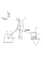
- a sensor 2 capable of measuring angular velocities around three axes is attached to the grip end of the golf club 1 via an adapter 3 as shown in FIGS.
- the sensor 2 in the present embodiment includes a casing 2a made of a box having a square shape in plan view, and the casing 2a can be fixed to the grip end by a double-sided tape, an adhesive, screwing, or the like.
- the golfer G is right-handed and is in an address state immediately before starting a swing for hitting the ball B set at a predetermined position.
- the sensor 2 is wireless, and the measured data is transmitted wirelessly to a wireless reception device (not shown) built in the computer 10 as a data analysis device.
- a wireless reception device built in the computer 10 as a data analysis device.
- Bluetooth Bluetooth (Bluetooth (Bluetooth is a registered trademark)) standard and technology can be used.
- the sensor 2 incorporates an angular velocity sensor (not shown) that can measure angular velocities around three axis directions (x-axis direction, y-axis direction, and z-axis direction).
- the sensor 2 further includes an A / D converter, a CPU, a wireless interface, a wireless antenna, and a power source.
- the power source for example, a button-type lithium ion battery or the like can be used.
- the battery may be rechargeable.
- the sensor 2 may include a charging circuit for charging the battery.
- An example of the sensor 2 that can be used is WAA-010 (trade name) manufactured by Wireless Technology.
- the wireless receiving device that receives a signal from the sensor 2 includes a wireless antenna, a wireless interface, a CPU, and a network interface.
- a computer 10 as a data analysis apparatus includes an input unit 6 including a keyboard 4 and a mouse 5 and a display unit 7. Although not shown, the computer 10 includes a hard disk, a memory, a CPU, and a network interface.
- Sensor 2 detects angular velocities around the x-axis, y-axis, and z-axis. These angular velocities are obtained as analog signals, and the analog signals are converted into digital signals by an A / D converter built in the sensor 2. The output from the A / D converter is transmitted to the CPU, and arithmetic processing such as primary filtering is executed. The data thus processed in the sensor 2 is transmitted from the wireless antenna to the wireless reception device built in the computer 10 via the wireless interface.
- the data transmitted from the sensor 2 is received by the wireless interface via the wireless antenna on the wireless receiving device side.
- the received data is processed by the CPU of the computer 10.
- the data sent to the computer 10 is recorded in a memory resource such as a hard disk.
- the hard disk stores programs and data necessary for data processing and the like.
- This program causes the CPU to execute necessary data processing.
- the CPU can execute various arithmetic processes, and the calculation results are output by the display unit 7 or a printing device (not shown).
- the relationship between the measurement axis and the golf club 1 is taken into consideration.
- the z-axis of the sensor 2 coincides with the shaft axis of the golf club 1.
- the x axis of the sensor 2 is oriented along the toe heel direction of the head 1 a of the golf club 1.
- the y-axis of the sensor 2 is oriented along the hitting direction.
- a polar coordinate system is considered, and the x-axis, y-axis, and z-axis of this polar coordinate system are a three-dimensional orthogonal coordinate system. More specifically, the z axis is the shaft axis of the golf club 1, and the x axis is oriented along the toe heel direction of the head 1a. Further, the y-axis is oriented along the hitting direction.
- the z-axis of the polar coordinate system coincides with the z-axis of the sensor 2
- the y-axis of the polar coordinate system coincides with the y-axis of the sensor 2.
- the x axis of the polar coordinate system coincides with the x axis of the sensor 2.
- Sensor 2 can obtain a plurality of continuous data in time series.
- the number of data per unit time depends on the sampling frequency.
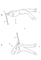
- FIGS. 4 to 7 are diagrams for explaining the swing from the address to the finish by the golfer.
- the swing includes a follow-through after impact, but the present invention focuses on the characteristics of the swing from address to impact.
- FIG. 4 to 7 are views of the golfer as seen from the front.
- the beginning of the swing is the address, and the end of the swing is called the finish.
- the swing proceeds in the order of (S1), (S2), (S3), (S4), (S5), (S6), (S7), and (S8).
- (S1) is an address
- (S2) is a takeback.
- (S3) in FIG. 5 is the top (top of swing). Usually, at the top, the moving speed of the head during the swing is minimum.
- S4) in FIG. 5 is a downswing.
- (S5) in FIG. 6 is also a downswing, the downswing is more advanced than (S4) in FIG. 6
- S6) is an impact, which is the moment when the head 1a of the golf club 1 and the ball B collide.
- (S7) is a follow-through
- (S8) is a finish. At the finish, the swing ends.
- FIG. 8 is a diagram showing the relationship between the time (s) from the address to the impact in a certain swing and the angular velocity ⁇ x (deg / s) around the x axis
- FIG. 9 is also the time from the address to the impact ( s) and the angular velocity ⁇ y (deg / s) around the y-axis
- FIG. 10 shows the time from the address to the impact (s) and the angular velocity ⁇ z (deg / s) around the z-axis. It is a figure which shows the relationship.
- time points A to D indicate the swing start time, the top of the swing, the time when the grip angular velocity around the y-axis (cock) becomes maximum, and the impact on the swing, respectively.
- predetermined index values are set according to the passage of time of the swing, and each index value is obtained by quantifying the grip angular velocity.
- the quantitative value (7) in FIG. 8 is ⁇ x_ ⁇ y_max to imp , which is an average value of grip angular velocities about the x-axis from when the grip angular velocities about the y-axis become maximum during the downswing to the impact.
- ⁇ z_top which is the amount of change in the grip angular velocity around the z axis near the top .
- the quantitative value (10) in FIG. 10 is ⁇ z_top to ⁇ y_max , which is the average value of the grip angular velocity around the z axis until the grip angular velocity around the y axis reaches the maximum during the downswing from the top. .
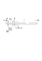
- FIG. 11 is a diagram illustrating a method for measuring the torque of the shaft 11 of the golf club 1.
- the rear end portion of the shaft 11 is fixed to be non-rotatable by the jig M1, and the front end portion of the shaft 11 is held by the jig M2, and 13.9 kgf ⁇ cm is positioned 40 mm from the tip end Tp. Torque Tr is applied.
- the torsion angle (degree) of the shaft 11 at this torque acting position is the shaft torque value.
- the rotational speed of the jig M2 when applying the torque Tr is 130 degrees / min or less, and the axial length between the jig M1 and the jig M2 is 825 mm. Furthermore, when the shaft 11 is deformed by gripping the jig M1 or the jig M2, the core 11 is filled in the shaft 11 and measurement is performed.
- the shaft of the golf club is selected based on the index value calculated using the quantified value (quantitative value) and the relationship between the torque matched to the golfer and the index value that has been obtained in advance by trial hitting.
- “near the top” means a time period including a predetermined time immediately before the top and a predetermined time immediately after the top. Specifically, for example, 100 ms from the top ⁇ 50 ms to the top +50 ms. Means the time zone.
- the “index value” in the present embodiment is a value calculated by quantifying the grip angular velocity, and is a value in which a correlation with the torque matched to the golfer is recognized.
- Matching with a golfer means that it is objectively evaluated by the standard deviation ⁇ of the variation in the right and left of the hit ball, such as the direction of the hit ball, and a golfer's sensory test (listening survey), such as the ease of swinging the club. ) May be evaluated.
- Index value (A) The magnitude of the amount of change in grip angular velocity per unit time around the x axis from when the y-axis grip angular velocity is maximized to the impact.
- This index value (A) is especially the direction of the hit ball It is a value that shows a correlation with the torque matched to the golfer in the sense of improving the performance.
- the directionality of the hit ball is determined by the orientation of the face immediately before the impact, but this face angle has a high correlation with the amount of change in the grip angular velocity around the x axis immediately before the impact.
- the index value (A) is calculated as follows. First, from the waveform of the grip angular velocity ⁇ y about the y-axis, t_ ⁇ y_max to imp , which is the time (t1) from when the y-axis grip angular velocity becomes maximum during the downswing to the impact, is calculated. Next, ⁇ x_ ⁇ y_max to imp , which is an average value (m1) of grip angular velocities around the x axis from when the y-axis grip angular velocities become maximum during the downswing to the impact, is calculated.
- Index value (B) Amount of change in grip angular velocity around the z-axis near the top
- Approximate expression representing the relationship between the torque matching the golfer and the index value (A) with respect to the directionality of the hit ball (for example, the above formula (1)) can be used to calculate the torque, but in order to improve the directionality, the index value (B) is used to stratify the relationship between the torque and the index value (A). can do.
- ⁇ z_top which is the amount of change in the grip angular velocity around the z-axis near the top, is positive when the face is closed.
- This ⁇ z_ top positive golfers, right hand at the top is swung down a golf club overlaying.
- the face is easy to close when covered by the right hand, so if you use a shaft with a small torque, the face will not open during the downswing, and the ball will be caught by impact, or you will use too much wrist and try to open the ball.
- the directionality deteriorates due to the appearance of sliced balls and sliced spheres. Therefore, Omegazui_ top positive golfer, is better to select the shaft torque is larger preferable.
- the golfer Omegazui_ top is negative or small, the face is in the direction of opening, as either face to impact open, the use of large shaft torque, wrist hated too open face in the downswing It closes and hooks and hook balls are likely to come out. Therefore, a golfer Omegazui_ top is negative or small, it is preferable to select a shaft torque is small.
- the stratified relationship between the torque and the index value (A) according to the size of Omegazui_ top it is preferable to use a suitable one approximation formula from a plurality of approximate expression prepared in advance.
- ⁇ x_ ⁇ y_max When the imp / t_ ⁇ y_max ⁇ imp and x, ⁇ z_ top 20 in the case of more than (deg), the following equation (2) an approximate expression representing the regression line obtained by the least squares method (first approximate expression) and, ⁇ z_ top can be 20 (in the case of less than deg), also the following equation (3) the approximate expression (second approximate expression).
- Torque (deg) -0.0000571x + 5.45
- Torque (deg) -0.0000571x + 4.70 (3)
- the index value (B) can be used for stratification when calculating the torque using the index value (A), but the index value (B) itself means that it improves the ease of swinging. This value is correlated with the torque matched to the golfer. Therefore, torque can also be calculated using this index value (B).
- the ease of swinging a golf club is the ease of timing, and it is considered that the golf club feels easy to swing when the swing and shaft twisting are synchronized.
- various tests (trial hits) were performed, and the ease of swinging was scored by a questionnaire and the correlation with the swing index value was confirmed.
- the golf club swingability was about the z axis near the top.
- correlation between Omegazui_ top is a variation of the grip angular velocity is found to be high. That is, a phenomenon similar to the stratification of fitting focusing on the directionality described above occurs, and it is considered that the index value (B) is connected to the timing of impact.
- Index value (C) The amount of change in the grip angular velocity around the z-axis until the maximum grip angular velocity on the y-axis is in the middle of the downswing from the top.
- the torque can be calculated by using an approximate expression (for example, the expression (4)) representing the relationship between the torque to be performed and the index value (B), but this index value ( C) can be used to stratify the relationship between the torque and the index value (B).
- the index value (C) can be calculated as follows. First, from the waveform of the grip angular velocity ⁇ y in the y-axis direction, t_top to ⁇ y_max , which is the time (t2) from the top to the time when the grip angular velocity of the y-axis becomes maximum during the downswing, is calculated. Next, ⁇ z_top ⁇ y_max, which is an average value (m2) of grip angular velocities around the z axis until the grip angular velocities on the y axis reach the maximum during the downswing from the top , is calculated.
- index value (C) ⁇ z_top ⁇ y_max / t_top ⁇ y_max
- a golfer with a large index value (C) has a large amount of shaft twist change (in the direction in which the face opens) at the beginning of the downswing.
- the negative absolute value is large
- the face is opened by itself. Therefore, if a shaft having a large torque is used, the face is opened too much or the variation becomes large, the timing is difficult to obtain, and the feeling deteriorates. Therefore, it is preferable that a golfer with a large index value (C) selects a shaft with a small torque.
- a golfer with a small index value (C) that is, a small amount of change in angular velocity, hardly opens and closes the face himself. Therefore, when a shaft with a small torque is used, the rotation of the face does not occur and the shaft feels hard. . Therefore, it is preferable that a golfer with a small index value (C) selects a shaft with a large torque.
- the relationship between the torque and the index value (B) is stratified according to the magnitude of ⁇ z_top to ⁇ y_max / t_top to ⁇ y_max , and one suitable approximation is selected from a plurality of approximation expressions prepared in advance. It is preferable to use the formula. For example, if the Omegazui_ top and x, when ⁇ z_ top ⁇ ⁇ y_max / t_ top ⁇ ⁇ y_max is -500 (deg) or less, the following equation (5) an approximate expression representing the regression line obtained by the least square method (No.
- the approximate expression can be obtained as follows, for example.
- As testers 20 right-handed men with handicap of 2-20 were prepared.
- As a golf club SRIXON Z-TX2 (club length: 45.0 inches, loft angle: 9.5 degrees) manufactured by Dunlop Sports Co., Ltd. was used.
- As shown in Table 1, three types of flexes (equivalent to X / S / R) are prepared as shafts, and torques of 3.0, 3.5, 4.0, 4.5 and 5. Five types of 0 were prepared.
- the head and shaft are detachable, and each tester made a test shot using the same head throughout the test. A tester with a high trajectory used a head with a loft standing, and a tester with a low trajectory used a head with a loft sleeping.
- the grip angular velocity was measured by the measurement method described with reference to FIG. Using a SRIXON Z-STAR XV manufactured by Dunlop Sports Co., Ltd. as a ball, a test shot of 25 balls in total for each club (shaft) was performed. However, the obvious miss shots were excluded and reworked. The directionality was evaluated by the standard deviation ⁇ of the left-right variation of the hit ball, and the shaft having the smallest ⁇ was determined as the shaft with good directionality. Further, the ease of swinging was determined by interviewing each tester with the shaft that was most likely to swing after trial-fitting five balls for each of the five types of shafts. The results are shown in Table 2.
- index values (A) to (C) described above were calculated using the measured grip angular velocity data.
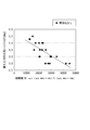
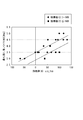
- Tables 3 to 4 show this calculation result and the most directional shaft torque evaluated by the standard deviation ⁇ of the left-right variation of the hit ball.
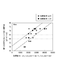
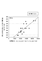
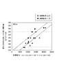
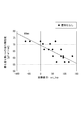
- Tables 5 to 6 show the calculation results and the shaft torque that was most easily determined, as determined by interview. Tables 3 to 6 correspond to FIGS. 12 to 15, respectively.
- Table 3 (FIG. 12) and Table 5 (FIG. 14) are not stratified by other index values, and Table 4 (FIG. 13) and Table 6 (FIG. 15) are layers by other index values. Separated.
- Table 4 (FIG. 13) is stratified according to whether the index value (B) is 20 or more and less than 20.
- Table 6 (FIG. 15) is stratified according to whether the index value (C) is ⁇ 500 or less and when it is greater than ⁇ 500.
- the fitting is performed based on the torsional rigidity of each of a plurality of portions along the shaft axial direction.
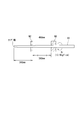
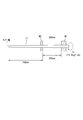
- FIG. 16 is a diagram for explaining a portion of the shaft 11 of the golf club 1 in which torsional rigidity is measured in the present embodiment.
- the torsional rigidity is measured at a plurality of portions along the axial direction of the shaft 11. Specifically, the torsional rigidity is measured at three portions, that is, the tip portion, the intermediate portion, and the rear end portion of the shaft 11.
- the torsional rigidity of the part 90 mm from the tip end of the shaft 11 is measured as the front end part
- the torsional rigidity of the part 490 mm from the tip end of the shaft 11 is measured as the intermediate part
- the torsional rigidity is 890 mm from the tip end of the shaft 11 as the rear end part.
- the torsional rigidity of the part is measured.
- the torsional rigidity is measured at three parts of the shaft 11.
- the torsional rigidity may be measured at two parts, for example, the front part and the rear part, or in the axial direction of the shaft 11. You may measure torsional rigidity in four different parts along.
- a portion 90 mm from the tip end of the shaft 11 is adopted as the tip portion of the shaft 11, but a portion within a range of 50 to 150 mm from the tip end can be used as the tip portion. .
- a portion 490 mm from the tip end of the shaft 11 is adopted as an intermediate portion of the shaft 11, but a portion within a range of 400 to 600 mm from the tip end may be set as the intermediate portion. it can.
- a portion 890 mm from the tip end of the shaft 11 is adopted as the rear end portion of the shaft 11, but a portion within a range of 800 to 1000 mm from the tip end is set as the rear end portion. Can do.
- GJ torsional rigidity
- the tip end side of the shaft 11 is fixed to be non-rotatable by the jig M2 on the basis of the portion where torsional rigidity is measured, and the rear end side of the shaft 11 is held by the jig M1.
- the positions of the jig M1 and the jig M2 differ depending on the part where the torsional rigidity is measured, as shown in FIGS.
- the jig M1 is disposed such that the end on the tip end side is located at a position 140 mm from the tip end, while the jig M2 is provided.
- the distance between the end of the jig M2 on the butt end side and the end of the jig M1 on the tip end side is the distance between the end of the jig M2 on the butt end side and the tip end side of the jig M1. It is set to 100 mm so that a portion 90 mm from the end of the chip is located in the middle of the end.
- the intermediate part (490 mm from the tip end) and the rear end part (890 mm from the tip end) are similarly arranged so that the intermediate part or the rear end part is positioned just between the jig M1 and the jig M2. And the position of the jig M2.
- a torque Tr of 13.9 kgf ⁇ cm is applied to a position 40 mm from the tip end.
- a torque Tr of 13.9 kgf ⁇ cm is applied to the position of 340 mm from the tip end, and the torsional rigidity of the rear end part (890 mm from the tip end) is applied.
- a torque Mr of 13.9 kgf ⁇ cm is applied to a position 740 mm from the tip end.
- the torsional rigidity value GJ (gf ⁇ m 2 / rad) is converted from the torsion angle ⁇ (rad) of the shaft 11 at the torque acting position described above.
- Tr the distance between the jig M1 and the jig M2
- l the distance between the jig M1 and the jig M2
- Tr Tr ⁇ l / ⁇ .
- the rotational speed of the jig M1 when applying the torque Tr is 130 degrees / minute or less. Furthermore, when the shaft 11 is deformed by gripping the jig M1 or the jig M2, the core 11 is filled in the shaft 11 and measurement is performed.
- the golf club shaft is selected based on the index value calculated using the quantified value (quantitative value) and the relationship between the index value and the torsional rigidity matched to the golfer, which was obtained in advance by trial hitting. To do. More specifically, the relationship between the torsional rigidity matched with the golfer and the index value is obtained in advance by trial hitting for each of the three parts (the tip part, the intermediate part, and the rear end part) of the shaft.
- the torsional rigidity suitable for the golfer is calculated.
- Such torsional rigidity is calculated for each of the three parts of the shaft.
- a shaft having a torsional rigidity characteristic closest to the calculated three torsional rigidity is selected from a plurality of shafts.
- part is measured previously, The measured torsional rigidity value is memorize
- the “index value” in the present embodiment is a value calculated by quantifying the grip angular velocity, and is a value in which a correlation with the torsional rigidity matched with the golfer is recognized.
- Examples of the “index value” include the following values. Matching with a golfer means that it is objectively evaluated by the standard deviation ⁇ of the variation in the right and left of the hit ball, such as the direction of the hit ball, and a golfer's sensory test (listening survey), such as the ease of swinging the club. ) May be evaluated.
- This index value (A) It is a value in which a correlation with the torque matched to the golfer is recognized in the sense of improving the directionality.
- the directionality of the hit ball is determined by the orientation of the face immediately before the impact, but this face angle has a high correlation with the amount of change in the grip angular velocity around the x axis immediately before the impact.
- the face cannot be opened, the loft angle at the time of impact is insufficient and the flight distance is insufficient.
- a shaft having a large torque a shaft having low torsional rigidity
- the face is appropriately opened to improve the directionality of the hit ball, and an appropriate loft angle can be obtained to increase the flight distance.
- the index value (A) is calculated as follows. First, from the waveform of the grip angular velocity ⁇ y around the y axis, t_ ⁇ y_max to imp , which is the time (t1) from when the grip angular velocity around the y axis reaches its maximum during the downswing , is calculated. Next, ⁇ x_ ⁇ y_max to imp , which is an average value (m1) of grip angular velocities around the x axis from when the grip angular velocities around the y axis reach the maximum during the downswing , is calculated.
- index value (A) ⁇ x_ ⁇ y_max ⁇ imp / t_ ⁇ y_max ⁇ imp
- the torsional rigidity GJ (torque) for each part is calculated based on the approximate expression representing the relationship between the two.
- GJ 490 (gf ⁇ m 2 /rad) 0.414x+88.8 (8)
- GJ 890 (gf ⁇ m 2 /rad) 0.0105x+83.3 (8)
- GJ 90 is the torsional rigidity at the tip part 90 mm from the tip end
- GJ 490 is the torsional rigidity at the intermediate part 490 mm from the tip end
- GJ 890 is the torsional rigidity at the rear end part 890 mm from the tip end.
- Index value (B) Amount of change in grip angular velocity about the z-axis near the top Approximate expression (for example, the relationship between the torsional rigidity matching the golfer and the index value (A) with respect to the directionality of the hit ball
- the torsional rigidity can be calculated using the equations (7) to (9)).
- the index value (B) is used to determine the torsional rigidity and the index value (A). Can be stratified.
- ⁇ z_top which is the amount of change in the grip angular velocity around the z-axis near the top, is positive when the face is closed.
- the Omegazui_ top positive golfers, and more particularly, the predetermined value or more positive golfer is right in the top is swung down golf club overlaying.
- the face is easy to close when covered with the right hand, so if you use a shaft with low torque (high torsional rigidity), the face will not open during the downswing, and the ball will be caught by impact or use your wrist too much to open it As a result, a sphere that cannot be caught or a sliced sphere appears and the directionality deteriorates. Therefore, Omegazui_ top positive golfer, torque is large (low torsional stiffness) it is preferable to select a shaft.
- the golfer Omegazui_ top is negative or small, the face is in the direction of opening, as either face to impact open, the use of large shaft torque, wrist hated too open face in the downswing It closes and hooks and hook balls are likely to come out. Therefore, a golfer Omegazui_ top is negative or small, it is preferable to select a shaft torque is small.
- the stratified relationship between torsional rigidity and the index value (A) according to the size of Omegazui_ top it is preferable to use a single approximate expression that is suitable from a plurality of approximate expression prepared in advance .
- ⁇ x_ ⁇ y_max ⁇ imp / t_ ⁇ y_max ⁇ imp and x ⁇ z_ top 20 if (deg / sec) or more
- the following equation (10) representing the regression line obtained by the least square method to (12) and the approximate expression (5 approximate expression) can be a Omegazui_ top 20 if (deg / sec) of less than, also the following equation (13) to approximate equation (15) (6 approximate expression) .
- the index value (B) can be used for stratification when calculating the torsional rigidity using the index value (A), but the index value (B) itself particularly improves the ease of swinging. It is a value in which a correlation with the torsional rigidity matched to the golfer is recognized in the meaning. Therefore, the torsional rigidity can be calculated using this index value (B).
- the ease of swinging a golf club is the ease of timing, and it is considered that the golf club feels easy to swing when the swing and shaft twisting are synchronized.
- various tests (trial hits) were performed, and the ease of swinging was scored by a questionnaire and the correlation with the swing index value was confirmed.
- the golf club swingability was about the z axis near the top.
- correlation between Omegazui_ top is a variation of the grip angular velocity is found to be high. That is, a phenomenon similar to the stratification of fitting focusing on the directionality described above occurs, and it is considered that the index value (B) is connected to the timing of impact.
- the torsional rigidity for each part can be calculated based on the approximate expression representing the relationship between the two. For example, if the Omegazui_ top and x, least squares method following expression for the regression line obtained by (16) to (18) can be approximate expression.
- Index value (C) The amount of change in the grip angular velocity around the z axis until the grip angular velocity around the y axis reaches the maximum during the downswing from the top.
- the torsional rigidity can be calculated using an approximate expression (for example, the above-described expressions (16) to (18)) representing the relationship between the matching torsional rigidity and the index value (B). Therefore, the index value (C) can be used to stratify the relationship between the torsional rigidity and the index value (B).
- the index value (C) can be calculated as follows. First, from the waveform of the grip angular velocity ⁇ y around the y-axis, t_top to ⁇ y_max , which is the time (t2) from the top to the time when the grip angular velocity around the y-axis becomes maximum during the downswing, is calculated. Next, ⁇ z_top ⁇ y_max, which is an average value (m2) of grip angular velocities around the z axis until the grip angular velocities on the y axis reach the maximum during the downswing from the top , is calculated.
- index value (C) ⁇ z_top ⁇ y_max / t_top ⁇ y_max
- a golfer with a large index value (C) has a large amount of shaft twist change (in the direction in which the face opens) at the beginning of the downswing. Especially when the negative absolute value is large, the face opens itself, so using a shaft with a large torque (low torsional rigidity) causes the face to open too much and the variation becomes large, making it difficult to keep timing. Gets worse. Therefore, it is preferable to select a shaft having a small torque (high torsional rigidity) for a golfer having a large index value (C).
- a golfer with a small index value (C) that is, a small amount of change in angular velocity, hardly opens and closes the face himself. Therefore, when a shaft with a small torque is used, the rotation of the face does not occur and the shaft feels hard. . Therefore, it is preferable to select a shaft having a large torque (low torsional rigidity) for a golfer having a small index value (C).
- the relationship between the torsional stiffness and the index value (B) is stratified according to the magnitude of ⁇ z_top to ⁇ y_max / t_top to ⁇ y_max , and one of the approximate expressions prepared in advance is suitable. It is preferable to use an approximate expression.
- the approximate expression can be obtained as follows, for example.
- As testers 20 right-handed men with handicap of 2-20 were prepared.
- As a golf club SRIXON Z-TX2 (club length: 45.0 inches, loft angle: 9.5 degrees) manufactured by Dunlop Sports Co., Ltd. was used.
- As shown in Table 1, three types of flexes (equivalent to X / S / R) are prepared as shafts, and the torsional rigidity of each flex is “high”, “medium”, “low”, “tip height” and Five kinds of "hand low” were prepared.
- the head and shaft are detachable, and each tester made a test shot using the same head throughout the test. A tester with a high trajectory used a head with a loft standing, and a tester with a low trajectory used a head with a loft sleeping.
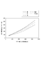
- FIG. 20 shows the torsional rigidity characteristics of five types of X-flexible shafts among the shafts used in the test. That is, the torsional rigidity distributions of five types of shafts with high torsional rigidity “high”, “medium”, “low”, “high tip” and “low hand” are shown.
- the horizontal axis represents the distance (mm) from the tip end of the shaft
- the vertical axis represents the torsional rigidity value (gf ⁇ m 2 / rad).
- the grip angular velocity was measured by the measurement method described with reference to FIG. Using a SRIXON Z-STAR XV manufactured by Dunlop Sports Co., Ltd. as a ball, a test shot of 25 balls in total for each club (shaft) was performed. However, the obvious miss shots were excluded and reworked. The directionality was evaluated by the standard deviation ⁇ of the left-right variation of the hit ball, and the shaft having the smallest ⁇ was determined as the shaft with good directionality. Further, the ease of swinging was determined by interviewing each tester with the shaft that was most likely to swing after trial-fitting five balls for each of the five types of shafts. The results are shown in Table 8.
- Tables 9 to 10 show the calculation results and the shaft torsional rigidity with the best direction evaluated by the standard deviation ⁇ of the left-right variation of the hit ball.
- Tables 11 to 12 show the calculation results and the shaft torsional rigidity that is the easiest to swing, as determined by interview.
- Tables 9 and 11 are not stratified by other index values, and Tables 10 and 12 are stratified by other index values.
- Table 10 is stratified according to whether the index value (B) is 20 or more and less than 20.
- Table 12 is stratified by the case where the index value (C) is ⁇ 500 or less and the case where it is larger than ⁇ 500.
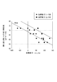
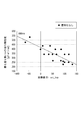
- FIGS. 21, 23 and 25 correspond to Table 9, and shaft torsional rigidity and indices with good directionality at the shaft tip portion (90 mm), the shaft middle portion (490 mm) and the shaft rear end portion (890 mm), respectively.
- An example of the relationship with the value (A) is shown, and the data is not stratified.
- FIGS. 22, 24, and 26 correspond to Table 10, and shaft torsional rigidity and indicators with good directionality at the shaft tip portion (90 mm), the shaft middle portion (490 mm), and the shaft rear end portion (890 mm), respectively.
- An example of the relationship with the value (A) is shown, and the data is stratified by the index value (B).
- FIGS. 28, 30 and 32 correspond to Table 12, and shaft torsional rigidity and index values that are easy to swing with respect to the shaft tip portion (90 mm), the shaft intermediate portion (490 mm), and the shaft rear end portion (890 mm), respectively.
- An example of the relationship with B) is shown, and the data is stratified by the index value (C).
- the torsional rigidity value suitable for the golfer is calculated for the three parts of the shaft (tip part, intermediate part and rear end part).
- a shaft having a torsional rigidity closest to these three torsional rigidity values is selected from a plurality of shafts. In each of the plurality of shafts, the torsional rigidity values at the three portions are measured in advance and stored in a database.
- the shaft that minimizes the sum of the difference between the calculated torsional rigidity value and the torsional rigidity value stored in the database for each part can be selected as the shaft that matches the golfer.
- fitting can be performed in the same manner.
Landscapes
- Health & Medical Sciences (AREA)
- Life Sciences & Earth Sciences (AREA)
- General Health & Medical Sciences (AREA)
- Physical Education & Sports Medicine (AREA)
- Biophysics (AREA)
- Physics & Mathematics (AREA)
- Medical Informatics (AREA)
- Animal Behavior & Ethology (AREA)
- Biomedical Technology (AREA)
- Heart & Thoracic Surgery (AREA)
- Pathology (AREA)
- Molecular Biology (AREA)
- Surgery (AREA)
- Engineering & Computer Science (AREA)
- Public Health (AREA)
- Veterinary Medicine (AREA)
- Geometry (AREA)
- Physiology (AREA)
- Dentistry (AREA)
- Oral & Maxillofacial Surgery (AREA)
- Golf Clubs (AREA)
Abstract
ゴルファーのスイングに基づいて当該ゴルファーにマッチしたトルクを有するシャフトを選定する、ゴルフクラブのシャフトのフィッティング方法。3軸回りの角速度を計測可能なセンサがグリップに取り付けられたゴルフクラブでゴルフボールを打撃して前記センサの計測値を得る工程と、前記計測値から定量化される前記角速度についての所定の指標値を得る工程と、予め試打により作成された、前記指標値とシャフトのトルクとの関係に基づいて、予めトルクが測定された複数のシャフトの中からゴルファーにマッチしたシャフトを選定する工程とを含んでいる。
Description
本発明はゴルフクラブのシャフトのフィッティング方法に関する。
ゴルファーにとってボールの飛距離を延ばすとともにボールを狙った方向・角度に飛ばすことは永遠のテーマである。そのためには、自身のスイングに合ったゴルフクラブを使用することが重要である。
ゴルファーに合ったゴルフクラブを選定することは一般にフィッティングと称されている。このフィッティングを効果的に行うためには、ゴルフクラブの全重量、クラブヘッドの重量、ゴルフクラブの長さなど種々のファクターを考慮する必要があるが、とりわけ、ゴルフクラブのシャフトの物性がフィッティングの良否に大きく影響する。
これまでのゴルフクラブシャフトのフィッティングでは、主にシャフトの曲げ剛性に着目した手法が多く提案されているが、シャフトの捻り剛性(トルク)に着目した手法については、あまり提案されていない。
しかし、ゴルフスイング中には、スイングすることによってシャフトが曲がることは事実であるが、ヘッドの重心がシャフト軸からずれていることや、スイング中にゴルファーの手首が動くことなどから、シャフトには曲がりと同時に捻り運動も発生している。この捻り運動も、打球の飛距離、方向性及びゴルフクラブの振り易さに大きく関係しており、特に方向性や振り易さについては、シャフトの捻り剛性が大きく影響している。
かかるシャフトのトルクに関し、従来の手法では、インパクト時のヘッドスピードや見た目のスイングテンポなどから経験的にトルクが決定されていたが、これらの手法はフィッティングを行う者(フィッター)の経験と勘に頼ることが多く、選定結果は客観的ではなく個人差が生じるという問題がある。
これに対し、センサを装着したゴルフクラブをユーザーにスイングしてもらい、得られるセンサデータを用いてゴルフクラブを設計・選定する技術が提案されている(例えば、特許文献1参照)。
特許文献1記載のゴルフクラブ設計装置・プログラムでは、センサデータを使用してシャフトの曲げや捻り剛性を規定しており、当該センサデータからユーザーの技量を関数化したスイング応答曲面を算出し、このスイング応答曲面により得られるゴルフクラブグリップの運動を変位データとして与え、クラブヘッドの動きを算出している。
しかし、特許文献1記載の方法では、加速度や角速度から変位を算出する際に積分の誤差が山積し、精度良く変位を算出することができないことから、捻り剛性を規定することが難しいという問題がある。さらに、特許文献1記載の方法では、捻り剛性を規定する方法が具体的に規定されていない。
本発明は、このような事情に鑑みてなされたものであり、ゴルファーのスイングにマッチしたトルクを有するシャフトを精度良く客観的にフィッティングすることができるゴルフクラブのシャフトのフィッティング方法を提供することを目的としている。
(1)本発明の第1の観点に係るゴルフクラブのシャフトのフィッティング方法(以下、単に「フィッティング方法」ともいう)は、ゴルファーのスイングに基づいて当該ゴルファーにマッチしたトルクを有するシャフトを選定する、ゴルフクラブのシャフトのフィッティング方法であって、
3軸回りの角速度を計測可能なセンサがグリップに取り付けられたゴルフクラブでゴルフボールを打撃して前記センサの計測値を得る工程と、
前記計測値から定量化される前記角速度についての所定の指標値を得る工程と、
予め試打により作成された、前記指標値とシャフトのトルクとの関係に基づいて、予めトルクが測定された複数のシャフトの中からゴルファーにマッチしたシャフトを選定する工程と
を含むことを特徴としている。
3軸回りの角速度を計測可能なセンサがグリップに取り付けられたゴルフクラブでゴルフボールを打撃して前記センサの計測値を得る工程と、
前記計測値から定量化される前記角速度についての所定の指標値を得る工程と、
予め試打により作成された、前記指標値とシャフトのトルクとの関係に基づいて、予めトルクが測定された複数のシャフトの中からゴルファーにマッチしたシャフトを選定する工程と
を含むことを特徴としている。
本発明の第1の観点に係るフィッティング方法では、グリップに取り付けられたセンサにより計測されるグリップ角速度を定量化して指標値を得、この指標値と、予め試打により作成された、前記指標値とシャフトのトルクとの関係とに基づいて、予めトルクが測定された複数のシャフトの中からゴルファーにマッチしたシャフトを選定する。したがって、ゴルファーのスイングにマッチしたトルクを有するシャフトを精度良く客観的にフィッティングすることができ、その結果、打球の飛距離、方向性及び振り易さを向上させることができる。
(2)前記(1)のフィッティング方法において、前記センサがグリップエンドに装着されていることが好ましい。
(3)前記(1)又は(2)のフィッティング方法において、x軸をゴルフクラブヘッドのトウーヒール方向に沿う方向に配向し、y軸を打球方向に沿うように配向し、z軸をシャフトの軸方向に一致するように配向したときに、
前記計測値からスイングにおけるアドレス、トップ及びインパクトを決定する工程、
ダウンスイング途中であってy軸のグリップ角速度が最大となるときからインパクトまでの時間であるt_ωy_max~impを計算する工程、
前記グリップ角速度が最大となるときからインパクトまでのx軸回りのグリップ角速度の平均値であるωx_ωy_max~impを計算する工程、
計算されたωx_ωy_max~impをt_ωy_max~impで除すことで、前記指標値としての、x軸回りの単位時間あたりのグリップ角速度変化量の大きさを計算する工程、及び
予め試打により用意された、前記x軸回りのグリップ角速度変化量の大きさとシャフトのトルクとの関係を示す近似式を用いて、前記計算されたx軸回りの単位時間あたりのグリップ角速度変化量の大きさからトルクを計算する工程
を含むものとすることができる。
前記計測値からスイングにおけるアドレス、トップ及びインパクトを決定する工程、
ダウンスイング途中であってy軸のグリップ角速度が最大となるときからインパクトまでの時間であるt_ωy_max~impを計算する工程、
前記グリップ角速度が最大となるときからインパクトまでのx軸回りのグリップ角速度の平均値であるωx_ωy_max~impを計算する工程、
計算されたωx_ωy_max~impをt_ωy_max~impで除すことで、前記指標値としての、x軸回りの単位時間あたりのグリップ角速度変化量の大きさを計算する工程、及び
予め試打により用意された、前記x軸回りのグリップ角速度変化量の大きさとシャフトのトルクとの関係を示す近似式を用いて、前記計算されたx軸回りの単位時間あたりのグリップ角速度変化量の大きさからトルクを計算する工程
を含むものとすることができる。
(4)前記(3)のフィッティング方法において、前記トルクを計算する工程において用いられる前記近似式として、トップ付近でのz軸回りのグリップ角速度の変化量であるωz_topの大きさに応じて用意された複数の近似式のうちの一つを用いてもよい。
(5)前記(4)のフィッティング方法において、前記複数の近似式のうち、前記ωz_topが20(deg/s)以上の場合に第1近似式を用い、20(deg/s)未満の場合に第2近似式を用いてもよい。
(6)前記(1)又は(2)のフィッティング方法において、x軸をゴルフクラブヘッドのトウーヒール方向に沿う方向に配向し、y軸を打球方向に沿うように配向し、z軸をシャフトの軸方向に一致するように配向したときに、
前記計測値からスイングにおけるアドレス、トップ及びインパクトを決定する工程、
前記指標値として、トップ付近でのz軸回りのグリップ角速度の変化量であるωz_topを計算する工程、及び
予め試打により用意された、前記z軸回りのグリップ角速度の変化量とシャフトのトルクとの関係を示す近似式を用いて、前記計算されたz軸回りのグリップ角速度の変化量からトルクを計算する工程
を含むものとすることができる。
前記計測値からスイングにおけるアドレス、トップ及びインパクトを決定する工程、
前記指標値として、トップ付近でのz軸回りのグリップ角速度の変化量であるωz_topを計算する工程、及び
予め試打により用意された、前記z軸回りのグリップ角速度の変化量とシャフトのトルクとの関係を示す近似式を用いて、前記計算されたz軸回りのグリップ角速度の変化量からトルクを計算する工程
を含むものとすることができる。
(7)前記(6)のフィッティング方法において、記トルクを計算する工程において用いられる前記近似式として、トップからダウンスイング途中であってy軸のグリップ角速度が最大となるときまでのz軸回りのグリップ角速度変化量の大きさに応じて用意された複数の近似式のうちの一つを用い、
前記z軸回りのグリップ角速度変化量の大きさが、トップからダウンスイング途中であってy軸のグリップ角速度が最大となるときまでのz軸回りのグリップ角速度の平均値であるωz_top~ωy_maxを、トップからダウンスイング途中であってy軸のグリップ角速度が最大となるときまでの時間であるt_top~ωy_maxで除した値としてもよい。
前記z軸回りのグリップ角速度変化量の大きさが、トップからダウンスイング途中であってy軸のグリップ角速度が最大となるときまでのz軸回りのグリップ角速度の平均値であるωz_top~ωy_maxを、トップからダウンスイング途中であってy軸のグリップ角速度が最大となるときまでの時間であるt_top~ωy_maxで除した値としてもよい。
(8)前記(7)のフィッティング方法において、前記複数の近似式のうち、前記除した値であるωz_top~ωy_max/t_top~ωy_maxが-500(deg/s2)以下の場合に第3近似式を用い、-500(deg/s2)より大きい場合に第4近似式を用いてもよい。
(9)本発明の第2の観点に係るフィッティング方法は、ゴルファーのスイングに基づいて当該ゴルファーにマッチした捻り剛性を有するシャフトを選定する、ゴルフクラブのシャフトのフィッティング方法であって、
3軸回りの角速度を計測可能なセンサがグリップに取り付けられたゴルフクラブでゴルフボールを打撃して前記センサの計測値を得る工程と、
前記計測値から定量化される前記角速度についての所定の指標値を得る工程と、
予め試打により作成された、前記指標値とシャフトの捻り剛性との関係に基づいて、予め捻り剛性が測定された複数のシャフトの中からゴルファーにマッチしたシャフトを選定する工程と
を含んでおり、
前記関係は、シャフトの軸方向の複数の部位について部位毎に作成されており、前記複数のシャフトは、当該部位毎の捻り剛性が測定されていることを特徴としている。
3軸回りの角速度を計測可能なセンサがグリップに取り付けられたゴルフクラブでゴルフボールを打撃して前記センサの計測値を得る工程と、
前記計測値から定量化される前記角速度についての所定の指標値を得る工程と、
予め試打により作成された、前記指標値とシャフトの捻り剛性との関係に基づいて、予め捻り剛性が測定された複数のシャフトの中からゴルファーにマッチしたシャフトを選定する工程と
を含んでおり、
前記関係は、シャフトの軸方向の複数の部位について部位毎に作成されており、前記複数のシャフトは、当該部位毎の捻り剛性が測定されていることを特徴としている。
本発明のフィッティング方法では、グリップに取り付けられたセンサにより計測されるグリップ角速度を定量化して指標値を得る。そして、この指標値と、シャフトの軸方向の複数の部位について予め試打により作成された、前記指標値とシャフトの捻り剛性との関係とに基づいて、予め捻り剛性が測定された複数のシャフトの中からゴルファーにマッチしたシャフトを選定する。この複数のシャフトは、前記複数の部位について部位毎の捻り剛性が測定されている。したがって、シャフト全体の捻り剛性に基づく先願発明よりも、ゴルファーのスイングにマッチした捻り剛性を有するシャフトをさらに精度良く客観的にフィッティングすることができる。その結果、打球の飛距離、方向性及び振り易さを向上させることができる。
(10)前記(9)のフィッティング方法において、前記複数の部位を、シャフトの先端部位、中間部位および後端部位の3つの部位とすることができる。
(11)前記(10)のフィッティング方法において、前記先端部位はシャフトの先端から50~150mmの間の部位であり、前記中間部位はシャフトの先端から400~600mmの間の部位であり、前記後端部位はシャフトの先端から800~1000mmの間の部位であってもよい。
(12)前記(11)のフィッティング方法において、前記先端部位はシャフトの先端から90mmの部位であり、前記中間部位はシャフトの先端から490mmの部位であり、前記後端部位はシャフトの先端から890mmの部位であってもよい。
(13)前記(9)~(12)のフィッティング方法において、前記センサがグリップエンドに装着されていてもよい。
(14)前記(9)~(13)のフィッティング方法において、前記センサのx軸をゴルフクラブヘッドのトウーヒール方向に沿う方向に配向し、前記センサのy軸を打球方向に沿うように配向し、前記センサのz軸をシャフトの軸方向に一致するように配向したときに、
前記計測値からスイングにおけるアドレス、トップ及びインパクトを決定する工程、
ダウンスイング途中であってy軸回りのグリップ角速度が最大となるときからインパクトまでの時間であるt_ωy_max~impを計算する工程、
前記グリップ角速度が最大となるときからインパクトまでのx軸回りのグリップ角速度の平均値であるωx_ωy_max~impを計算する工程、
計算されたωx_ωy_max~impをt_ωy_max~impで除すことで、前記指標値としての、x軸回りの単位時間あたりのグリップ角速度変化量の大きさを計算する工程、及び
前記複数の部位について予め試打により用意された、前記x軸回りのグリップ角速度変化量の大きさとシャフトの捻り剛性との関係を示す近似式を用いて、前記計算されたx軸回りの単位時間あたりのグリップ角速度変化量の大きさから各部位の捻り剛性を計算する工程
を含むことができる。
前記計測値からスイングにおけるアドレス、トップ及びインパクトを決定する工程、
ダウンスイング途中であってy軸回りのグリップ角速度が最大となるときからインパクトまでの時間であるt_ωy_max~impを計算する工程、
前記グリップ角速度が最大となるときからインパクトまでのx軸回りのグリップ角速度の平均値であるωx_ωy_max~impを計算する工程、
計算されたωx_ωy_max~impをt_ωy_max~impで除すことで、前記指標値としての、x軸回りの単位時間あたりのグリップ角速度変化量の大きさを計算する工程、及び
前記複数の部位について予め試打により用意された、前記x軸回りのグリップ角速度変化量の大きさとシャフトの捻り剛性との関係を示す近似式を用いて、前記計算されたx軸回りの単位時間あたりのグリップ角速度変化量の大きさから各部位の捻り剛性を計算する工程
を含むことができる。
(15)前記(14)のフィッティング方法において、前記捻り剛性を計算する工程において用いられる前記近似式として、トップ付近でのz軸回りのグリップ角速度の変化量であるωz_topの大きさに応じて用意された複数の近似式のうちの一つを用いることができる。
(16)前記(15)のフィッティング方法において、前記複数の近似式のうち、前記ωz_topが20(deg/s)以上の場合に第5近似式を用い、20(deg/s)未満の場合に第6近似式を用いることができる。
(17)前記(9)~(13)のフィッティング方法において、前記センサのx軸をゴルフクラブヘッドのトウーヒール方向に沿う方向に配向し、前記センサのy軸を打球方向に沿うように配向し、前記センサのz軸をシャフトの軸方向に一致するように配向したときに、
前記計測値からスイングにおけるアドレス、トップ及びインパクトを決定する工程、
前記指標値として、トップ付近でのz軸回りのグリップ角速度の変化量であるωz_topを計算する工程、及び
前記複数の部位について予め試打により用意された、前記z軸回りのグリップ角速度の変化量とシャフトの捻り剛性との関係を示す近似式を用いて、前記計算されたz軸回りのグリップ角速度の変化量から各部位の捻り剛性を計算する工程
を含むことができる。
前記計測値からスイングにおけるアドレス、トップ及びインパクトを決定する工程、
前記指標値として、トップ付近でのz軸回りのグリップ角速度の変化量であるωz_topを計算する工程、及び
前記複数の部位について予め試打により用意された、前記z軸回りのグリップ角速度の変化量とシャフトの捻り剛性との関係を示す近似式を用いて、前記計算されたz軸回りのグリップ角速度の変化量から各部位の捻り剛性を計算する工程
を含むことができる。
(18)前記(17)のフィッティング方法において、前記捻り剛性を計算する工程において用いられる前記近似式として、トップからダウンスイング途中であってy軸回りのグリップ角速度が最大となるときまでのz軸回りのグリップ角速度変化量の大きさに応じて用意された複数の近似式のうちの一つを用い、
前記z軸回りのグリップ角速度変化量の大きさが、トップからダウンスイング途中であってy軸回りのグリップ角速度が最大となるときまでのz軸回りのグリップ角速度の平均値であるωz_top~ωy_maxを、トップからダウンスイング途中であってy軸回りのグリップ角速度が最大となるときまでの時間であるt_top~ωy_maxで除した値とすることができる。
前記z軸回りのグリップ角速度変化量の大きさが、トップからダウンスイング途中であってy軸回りのグリップ角速度が最大となるときまでのz軸回りのグリップ角速度の平均値であるωz_top~ωy_maxを、トップからダウンスイング途中であってy軸回りのグリップ角速度が最大となるときまでの時間であるt_top~ωy_maxで除した値とすることができる。
(19)前記(18)のフィッティング方法において、前記複数の近似式のうち、前記除した値であるωz_top~ωy_max/t_top~ωy_maxが-500(deg/s2)より大きい場合に第7近似式を用い、-500(deg/s2)以下の場合に第8近似式を用いることができる。
本発明のフィッティング方法によれば、ゴルファーのスイングにマッチしたトルク又は捻り剛性を有するシャフトを精度良く客観的にフィッティングすることができ、その結果、打球の飛距離、方向性及び振り易さを向上させることができる。
以下、添付図面を参照しつつ、本発明のフィッティング方法の実施の形態を詳細に説明する。
本発明のフィッティング方法では、3軸方向の角速度が測定可能なセンサが取り付けられたゴルフクラブをゴルファーにスイングしてもらい、得られる角速度をスイングの区間又は時間帯(例えば、y軸回り(コック方向)のグリップ角速度が最大となるときからインパクトまでの時間)で定量化した値を用いて導かれる指標値に基づいて、当該ゴルファーにマッチしたトルク又は捻り剛性を有するゴルフクラブシャフトを選定している。
より詳細には、シャフト全体の捻り剛性であるトルク、又は、シャフト軸方向に沿った複数の部位それぞれの捻り剛性に基づいてフィッティングを行っている。これにより、フィッティングの精度を向上させることができ、打球の飛距離、方向性及び振り易さを向上させることができる。
本発明では、図1に示されるように、ゴルフクラブのフィッティングを希望するゴルファーに実際にスイングをしてもらい、そのスイングから、当該ゴルファーに特有の「指標値」を算出している。ゴルフクラブ1のグリップエンドには、図2~3に示されるように、3軸回りの角速度を計測することができるセンサ2がアダプター3を介して取り付けられている。本実施の形態におけるセンサ2は、平面視正方形状の箱体からなるケーシング2aを備えており、このケーシング2aは、両面テープ、接着剤、ねじ止めなどによりグリップエンドに固定することができる。図1に示される例では、ゴルファーGは右利きであり、所定位置にセットされたボールBを打撃するためのスイングを開始する直前のアドレス状態である。
なお、フィッティングの精度を向上させるために、ユーザーのマイクラブの長さが、データベースに記憶されているシャフトに基づくゴルフクラブの長さと異なる場合は、データベースで準備したクラブ長さ相当のクラブ総重量に変更することで、当該ユーザーにマッチしたシャフトを選定することができる。例えば、データベースに記憶されているクラブの長さが45インチであり、ユーザーのクラブ長さA(mm)が、45インチ(=1143mm)と異なる場合、計測のためにスイングするクラブの総重量を次の式により算出したもの(45インチ相当の総重量)に変更して、フィッティングを行う。
(計測に活用するクラブ総重量)=(A-1143)×0.377+(マイクラブのクラブ総重量)
(計測に活用するクラブ総重量)=(A-1143)×0.377+(マイクラブのクラブ総重量)
センサ2は無線式であり、測定されたデータは、無線により、データ解析装置としてのコンピュータ10に内蔵された無線受信装置(図示せず)に送信される。無線通信として、例えばBluetooth(ブルートゥース(Bluetoothは登録商標である。))の規格及び技術を用いることができる。
センサ2は、3軸方向(x軸方向、y軸方向、及びz軸方向)回りの角速度を計測することができる角速度センサ(図示せず)を内蔵している。センサ2は、更に、A/D変換器、CPU、無線インターフェース、無線アンテナ及び電源を備えている。電源としては、例えばボタン型のリチウムイオン電池などを用いることができる。電池は充電可能なものであってもよい。そして、センサ2は、電池を充電するための充電回路を備えていてもよい。使用可能なセンサ2の例としては、ワイヤレステクノロジー社製のWAA-010(商品名)をあげることができる。
なお、センサ2からの信号を受信する前記無線受信装置は、無線アンテナ、無線インターフェース、CPU及びネットワークインターフェースを備えている。
データ解析装置としてのコンピュータ10は、キーボード4及びマウス5からなる入力部6と、表示部7とを備えている。また、図示していないが、コンピュータ10は、ハードディスク、メモリ、CPU及びネットワークインターフェースを備えている。
センサ2は、x軸、y軸及びz軸の各軸回りの角速度を検知する。これらの角速度はアナログ信号として得られ、このアナログ信号は、センサ2に内蔵されているA/D変換器によってデジタル信号に変換される。A/D変換器からの出力はCPUに伝達されて1次フィルタリングなどの演算処理が実行される。こうしてセンサ2内で処理されたデータは、無線インターフェースを介して、無線アンテナからコンピュータ10に内蔵された無線受信装置に送信される。
センサ2から送信されたデータは、無線受信装置側の無線アンテナを介して、無線インターフェースによって受信される。受信されたデータは、コンピュータ10のCPUで演算処理される。
コンピュータ10に送られたデータは、ハードディスクなどのメモリ資源に記録される。ハードディスクには、データ処理などに必要なプログラム及びデータなどが記憶されている。このプログラムは、CPUに、必要なデータ処理を実行させる。CPUは、各種の演算処理を実行可能であり、演算結果は、表示部7又は図示しない印刷装置などによって出力される。
センサ2のグリップエンドへの取付に際しては、計測軸とゴルフクラブ1との関係が考慮される。後述する実施形態では、センサ2のz軸がゴルフクラブ1のシャフト軸に一致している。センサ2のx軸は、ゴルフクラブ1のヘッド1aのトウーヒール方向に沿うように配向される。また、センサ2のy軸は打球方向に沿うように配向される。このようにセンサ2を取り付けることで、演算を簡略化することができる。
後述する実施形態では、極座標系が考慮され、この極座標系のx軸、y軸及びz軸は、三次元直交座標系である。より詳細には、z軸が前記ゴルフクラブ1のシャフト軸とされ、x軸は、ヘッド1aのトウーヒール方向に沿うように配向される。また、y軸は打球方向に沿うように配向される。
すなわち、極座標系のz軸は、センサ2のz軸に一致しており、極座標系のy軸は、センサ2のy軸に一致している。また、極座標系のx軸は、センサ2のx軸に一致している。
センサ2によって、時系列的に連続した複数のデータを得ることができる。単位時間当たりのデータ数は、サンプリング周波数に依存する。
図4~7は、ゴルファーによるアドレスからフィニッシュまでのスイングを説明する図である。スイングには、インパクト後のフォロースルーが含まれるが、本発明では、アドレスからインパクトまでのスイングの特徴に着目している。
図4~7は、ゴルファーを正面から見た図である。スイングの始まりはアドレスであり、スイングの終わりはフィニッシュと呼ばれている。スイングは、(S1)、(S2)、(S3)、(S4)、(S5)、(S6)、(S7)、(S8)の順で進行する。図4の(S1)がアドレスであり、(S2)がテイクバックである。図5の(S3)がトップ(トップオブスイング)である。通常、トップでは、スイング中におけるヘッドの移動速度が最小である。図5の(S4)はダウンスイングである。図6の(S5)もダウンスイングであるが、図5の(S4)よりもダウンスイングが進行した状態である。図6の(S6)はインパクトであり、ゴルフクラブ1のヘッド1aとボールBとが衝突した瞬間である。図7の(S7)はフォロースルーであり、(S8)はフィニッシュである。フィニッシュで、スイングが終了する。
図8は、或るスイングにおけるアドレスからインパクトまでの時間(s)とx軸回りの角速度ωx(deg/s)との関係を示す図であり、図9は、同じくアドレスからインパクトまでの時間(s)とy軸回りの角速度ωy(deg/s)との関係を示す図であり、図10は、同じくアドレスからインパクトまでの時間(s)とz軸回りの角速度ωz(deg/s)との関係を示す図である。図8~10において、時点A~Dは、それぞれスイング開始時点、スイングのトップ、y軸(コック)回りのグリップ角速度が最大となる時点、及びスイングにおけるインパクトを示している。後述する実施形態では、図8~10に示されるように、スイングの時間経過にしたがって所定の指標値を設定し、各指標値をグリップ角速度を定量化することで求めている。例えば、図8における定量値(7)は、ダウンスイング途中であってy軸回りのグリップ角速度が最大となるときからインパクトまでのx軸回りのグリップ角速度の平均値であるωx_ωy_max~impである。また、図10における定量値(9)は、トップ付近でのz軸回りのグリップ角速度の変化量であるωz_topである。また、図10における定量値(10)は、トップからダウンスイング途中であってy軸回りのグリップ角速度が最大となるときまでのz軸回りのグリップ角速度の平均値であるωz_top~ωy_maxである。
〔第1実施形態〕
本実施形態では、シャフト全体の捻り剛性であるトルクに基づいてフィッティングを行っている。
図11は、ゴルフクラブ1のシャフト11のトルクを計測する方法を説明する図である。この計測方法では、シャフト11の後端部を治具M1により回転不能に固定するとともに、シャフト11の先端部を治具M2で把持し、チップ端Tpから40mmの位置に13.9kgf・cmのトルクTrを作用させる。そして、このトルク作用位置でのシャフト11の捩れ角(度)がシャフトトルク値とされる。なお、トルクTrを負荷する際の治具M2の回転速度は130度/分以下とし、治具M1と治具M2との間の軸方向長さは825mmとする。さらに、治具M1又は治具M2の把持によってシャフト11が変形する場合、当該シャフト11の内部に芯材などを充填させて計測を行うものとする。
本実施形態では、シャフト全体の捻り剛性であるトルクに基づいてフィッティングを行っている。
図11は、ゴルフクラブ1のシャフト11のトルクを計測する方法を説明する図である。この計測方法では、シャフト11の後端部を治具M1により回転不能に固定するとともに、シャフト11の先端部を治具M2で把持し、チップ端Tpから40mmの位置に13.9kgf・cmのトルクTrを作用させる。そして、このトルク作用位置でのシャフト11の捩れ角(度)がシャフトトルク値とされる。なお、トルクTrを負荷する際の治具M2の回転速度は130度/分以下とし、治具M1と治具M2との間の軸方向長さは825mmとする。さらに、治具M1又は治具M2の把持によってシャフト11が変形する場合、当該シャフト11の内部に芯材などを充填させて計測を行うものとする。
[指標値]
本実施形態では、前述したスイングにおける種々の段階のうちトップ付近からインパクトに至るダウンスイング中のグリップ角速度に着目し、時間経過にしたがって当該角速度を細分化して定量化する。そして、定量化した値(定量値)を用いて算出される指標値と、予め試打により求めておいた、ゴルファーにマッチしたトルクと指標値との関係に基づいて、ゴルフクラブのシャフトを選定する。なお、本明細書において「トップ付近」とは、トップ直前の所定時間及びトップ直後の所定時間を含む時間帯を意味しており、具体的には、例えばトップ-50msから、トップ+50msまでの100msの時間帯を意味している。
本実施形態では、前述したスイングにおける種々の段階のうちトップ付近からインパクトに至るダウンスイング中のグリップ角速度に着目し、時間経過にしたがって当該角速度を細分化して定量化する。そして、定量化した値(定量値)を用いて算出される指標値と、予め試打により求めておいた、ゴルファーにマッチしたトルクと指標値との関係に基づいて、ゴルフクラブのシャフトを選定する。なお、本明細書において「トップ付近」とは、トップ直前の所定時間及びトップ直後の所定時間を含む時間帯を意味しており、具体的には、例えばトップ-50msから、トップ+50msまでの100msの時間帯を意味している。
本実施形態における「指標値」は、グリップ角速度の定量化により算出される値であり、ゴルファーにマッチしたトルクとの相関関係が認められる値のことであり、例えば、以下のような値を例示することができる。なお、ゴルファーにマッチしたとは、打球の方向性のように打球の左右ばらつきの標準偏差σなどにより客観的に評価される場合と、クラブの振り易さのようにゴルファーの官能試験(聞き取り調査)で評価される場合とがある。
(1)指標値(A):y軸のグリップ角速度が最大となるときからインパクトまでのx軸回りの単位時間あたりのグリップ角速度変化量の大きさ
この指標値(A)は、特に打球の方向性を良くする意味においてゴルファーにマッチしたトルクとの相関が認められる値である。打球の方向性はインパクト直前のフェースの向きによって決まるが、このフェース角はインパクト直前のx軸回りのグリップ角速度変化量と相関が高い。すなわち、インパクト直前のx軸回りの角速度変化量が大きいほど、ヘッドが急激に加速されるので、インパクトの瞬間にフェース方向が乱れ易く、また開き易くなる。このようなゴルファーに対しトルクの小さいシャフトを選定すると、フェース角のばらつきが小さくなるとともにフェースの開きが抑えられて、打球の方向制が改善される。逆の場合も同様に、インパクト直前のx軸回りの角速度変化量が小さいと、自らフェースを開くことができず、ボールを引っ掛けてしまい易くなり、打球の方向性が悪くなる。また、フェースを開くことができないと、インパクト時のロフト角が不足して飛距離が不足する。このようなゴルファーに対しトルクの大きいシャフトを選定すると、フェースが適度に開いて打球の方向性が改善されるとともに、適度なロフト角も得られ飛距離が延びる。
この指標値(A)は、特に打球の方向性を良くする意味においてゴルファーにマッチしたトルクとの相関が認められる値である。打球の方向性はインパクト直前のフェースの向きによって決まるが、このフェース角はインパクト直前のx軸回りのグリップ角速度変化量と相関が高い。すなわち、インパクト直前のx軸回りの角速度変化量が大きいほど、ヘッドが急激に加速されるので、インパクトの瞬間にフェース方向が乱れ易く、また開き易くなる。このようなゴルファーに対しトルクの小さいシャフトを選定すると、フェース角のばらつきが小さくなるとともにフェースの開きが抑えられて、打球の方向制が改善される。逆の場合も同様に、インパクト直前のx軸回りの角速度変化量が小さいと、自らフェースを開くことができず、ボールを引っ掛けてしまい易くなり、打球の方向性が悪くなる。また、フェースを開くことができないと、インパクト時のロフト角が不足して飛距離が不足する。このようなゴルファーに対しトルクの大きいシャフトを選定すると、フェースが適度に開いて打球の方向性が改善されるとともに、適度なロフト角も得られ飛距離が延びる。
前記指標値(A)は、次のようにして算出される。
まず、y軸回りのグリップ角速度ωyの波形から、ダウンスイング途中であってy軸のグリップ角速度が最大となるときからインパクトまでの時間(t1)であるt_ωy_max~impを計算する。
ついで、ダウンスイング途中であってy軸のグリップ角速度が最大となるときからインパクトまでのx軸回りのグリップ角速度の平均値(m1)であるωx_ωy_max~impを計算する。
まず、y軸回りのグリップ角速度ωyの波形から、ダウンスイング途中であってy軸のグリップ角速度が最大となるときからインパクトまでの時間(t1)であるt_ωy_max~impを計算する。
ついで、ダウンスイング途中であってy軸のグリップ角速度が最大となるときからインパクトまでのx軸回りのグリップ角速度の平均値(m1)であるωx_ωy_max~impを計算する。
ついで、前記平均値(m1)を前記時間(t1)で除することで、y軸のグリップ角速度が最大となるときからインパクトまでのx軸回りの単位時間あたりのグリップ角速度変化量の大きさである指標値(A)を求める。
指標値(A)=ωx_ωy_max~imp/t_ωy_max~imp
このようにして算出された指標値(A)と、予め試打により求めておいた、打球の方向性についてゴルファーにマッチするトルクと指標値(A)との関係に基づいて、具体的には両者の関係を表す近似式に基づいて、トルクを計算する。
例えば、ωx_ωy_max~imp/t_ωy_max~impをxとすると、最小二乗法により求められる回帰直線を表す以下の式(1)を近似式とすることができる。
トルク(deg)=-0.0000547x+5.17 ・・・・・・(1)
指標値(A)=ωx_ωy_max~imp/t_ωy_max~imp
このようにして算出された指標値(A)と、予め試打により求めておいた、打球の方向性についてゴルファーにマッチするトルクと指標値(A)との関係に基づいて、具体的には両者の関係を表す近似式に基づいて、トルクを計算する。
例えば、ωx_ωy_max~imp/t_ωy_max~impをxとすると、最小二乗法により求められる回帰直線を表す以下の式(1)を近似式とすることができる。
トルク(deg)=-0.0000547x+5.17 ・・・・・・(1)
(2)指標値(B):トップ付近でのz軸回りのグリップ角速度の変化量
打球の方向性についてゴルファーにマッチするトルクと指標値(A)との関係を表す近似式(例えば、前記式(1))を用いてトルクを計算することができるが、より方向性をよくするために、この指標値(B)を用いて、前記トルクと指標値(A)との関係を層別化することができる。
打球の方向性についてゴルファーにマッチするトルクと指標値(A)との関係を表す近似式(例えば、前記式(1))を用いてトルクを計算することができるが、より方向性をよくするために、この指標値(B)を用いて、前記トルクと指標値(A)との関係を層別化することができる。
トップ付近でのz軸回りのグリップ角速度の変化量であるωz_topは、フェースを閉じる向きを正とする。このωz_topが正のゴルファーは、トップにおいて右手が被さってゴルフクラブが振り下ろされる。右手が被ることでフェースは閉じ易くなるので、トルクの小さいシャフトを使用すると、ダウンスイング中にフェースが開かずインパクトでボールを引っ掛けるか、又は、開こうとして手首を使いすぎてしまい、捕まらない球が出たりスライス球が出たりして方向性が悪化する。したがって、ωz_topが正のゴルファーは、トルクが大きいシャフトを選択する方が好ましい。
一方、ωz_topが負又は小さいゴルファーは、フェースが開く方向にあるので、そのままフェースが開いてインパクトをするか、トルクの大きいシャフトを使用すると、ダウンスイング中のフェースが開きすぎを嫌って手首が閉じてしまい、引っ掛けやフック球が出易くなる。したがって、ωz_topが負又は小さいゴルファーは、トルクが小さいシャフトを選択することが好ましい。
以上より、ωz_topの大きさに応じて前記トルクと指標値(A)との関係を層別化し、予め用意された複数の近似式の中から適した1つの近似式を用いることが好ましい。
例えば、ωx_ωy_max~imp/t_ωy_max~impをxとすると、ωz_topが20(deg)以上の場合に、最小二乗法により求められる回帰直線を表す以下の式(2)を近似式(第1近似式)とし、ωz_topが20(deg)未満の場合に、同じく以下の式(3)を近似式(第2近似式)とすることができる。
トルク(deg)=-0.0000571x+5.45 ・・・・・・(2)
トルク(deg)=-0.0000571x+4.70 ・・・・・・(3)
例えば、ωx_ωy_max~imp/t_ωy_max~impをxとすると、ωz_topが20(deg)以上の場合に、最小二乗法により求められる回帰直線を表す以下の式(2)を近似式(第1近似式)とし、ωz_topが20(deg)未満の場合に、同じく以下の式(3)を近似式(第2近似式)とすることができる。
トルク(deg)=-0.0000571x+5.45 ・・・・・・(2)
トルク(deg)=-0.0000571x+4.70 ・・・・・・(3)
前記指標値(B)は、指標値(A)を用いてトルクを計算する際の層別化に利用することができるが、この指標値(B)自体は、特に振り易さを改善する意味においてゴルファーにマッチしたトルクとの相関が認められる値である。したがって、この指標値(B)を用いてトルクを計算することもできる。
ゴルフクラブの振り易さとはタイミングの取り易さのことであり、スイングとシャフトの捩れ方が同調すると振り易いと感じるものと考えられる。本発明は、種々のテスト(試打)を行い、アンケートにて振り易さを点数化し、スイング指標値との相関を確認したところ、ゴルフクラブの振り易さは、トップ付近でのz軸回りのグリップ角速度の変化量であるωz_topとの相関が高いことが分かった。すなわち、前述した方向性に着目したフィッティングの層別化と同様の現象が起きており、指標値(B)がインパクトのタイミングに繋がっていると考えられる。
したがって、指標値(B)と、予め試打により求めておいた、ゴルフクラブの振り易さについてゴルファーにマッチするトルクと指標値(B)との関係に基づいて、具体的には両者の関係を表す近似式に基づいて、トルクを計算することができる。
例えば、ωz_topをxとすると、最小二乗法により求められる回帰直線を表す以下の式(4)を近似式とすることができる。
トルク(deg)=0.00939x+3.38 ・・・・・・(4)
例えば、ωz_topをxとすると、最小二乗法により求められる回帰直線を表す以下の式(4)を近似式とすることができる。
トルク(deg)=0.00939x+3.38 ・・・・・・(4)
(3)指標値(C):トップからダウンスイング途中であってy軸のグリップ角速度が最大となるときまでのz軸回りのグリップ角速度変化量の大きさ
ゴルフクラブの振り易さについてゴルファーにマッチするトルクと指標値(B)との関係を表す近似式(例えば、前記式(4))を用いてトルクを計算することができるが、より振り易さを良くするために、この指標値(C)を用いて、前記トルクと指標値(B)との関係を層別化することができる。
ゴルフクラブの振り易さについてゴルファーにマッチするトルクと指標値(B)との関係を表す近似式(例えば、前記式(4))を用いてトルクを計算することができるが、より振り易さを良くするために、この指標値(C)を用いて、前記トルクと指標値(B)との関係を層別化することができる。
指標値(C)は、以下のようにして算出することができる。
まず、y軸方向のグリップ角速度ωyの波形から、トップからダウンスイング途中であってy軸のグリップ角速度が最大となるときまでの時間(t2)であるt_top~ωy_maxを計算する。
ついで、トップからダウンスイング途中であってy軸のグリップ角速度が最大となるときまでのz軸回りのグリップ角速度の平均値(m2)であるωz_top~ωy_maxを計算する。
まず、y軸方向のグリップ角速度ωyの波形から、トップからダウンスイング途中であってy軸のグリップ角速度が最大となるときまでの時間(t2)であるt_top~ωy_maxを計算する。
ついで、トップからダウンスイング途中であってy軸のグリップ角速度が最大となるときまでのz軸回りのグリップ角速度の平均値(m2)であるωz_top~ωy_maxを計算する。
ついで、前記平均値(m2)を前記時間(t2)で除することで、トップからダウンスイング途中であってy軸のグリップ角速度が最大となるときまでのz軸回りのグリップ角速度変化量の大きさである指標値(C)を求める。
指標値(C)=ωz_top~ωy_max/t_top~ωy_max
指標値(C)=ωz_top~ωy_max/t_top~ωy_max
この指標値(C)が大きいゴルファーは、ダウンスイング初期のシャフト捩れの変化量(フェースが開く方向)が大きい。特に負の絶対値が大きい場合は、自らフェースを開いているので、トルクの大きいシャフトを使用すると、フェースが開きすぎたりばらつきが大きくなったりし、タイミングが取りづらくフィーリングが悪化する。したがって、指標値(C)が大きいゴルファーは、トルクの小さいシャフトを選択することが好ましい。
一方、指標値(C)が小さい、すなわち角速度変化量が小さいゴルファーは、自分でフェースの開閉をほとんどしないので、トルクの小さいシャフトを使用すると、フェースのローテーションが起こらず、シャフトを硬く感じたりする。したがって、指標値(C)が小さいゴルファーは、トルクの大きいシャフトを選択することが好ましい。
以上より、ωz_top~ωy_max/t_top~ωy_maxの大きさに応じて前記トルクと指標値(B)との関係を層別化し、予め用意された複数の近似式の中から適した1つの近似式を用いることが好ましい。
例えば、ωz_topをxとすると、ωz_top~ωy_max/t_top~ωy_maxが-500(deg)以下の場合に、最小二乗法により求められる回帰直線を表す以下の式(5)を近似式(第3近似式)とし、ωz_top~ωy_max/t_top~ωy_maxが-500(deg)より大きい場合に、同じく以下の式(6)を近似式(第4近似式)とすることができる。
トルク(deg)=0.00991x+3.50 ・・・・・・(5)
トルク(deg)=0.00991x+2.90 ・・・・・・(6)
例えば、ωz_topをxとすると、ωz_top~ωy_max/t_top~ωy_maxが-500(deg)以下の場合に、最小二乗法により求められる回帰直線を表す以下の式(5)を近似式(第3近似式)とし、ωz_top~ωy_max/t_top~ωy_maxが-500(deg)より大きい場合に、同じく以下の式(6)を近似式(第4近似式)とすることができる。
トルク(deg)=0.00991x+3.50 ・・・・・・(5)
トルク(deg)=0.00991x+2.90 ・・・・・・(6)
[近似式の求め方]
前記近似式は、例えば以下のようにして求めることができる。
テスターとして、ハンディキャップが2~20までの右利き男性20名を用意した。ゴルフクラブとして、ダンロップスポーツ株式会社製のSRIXON Z-TX2(クラブ長さ:45.0インチ、ロフト角:9.5度)を使用した。表1に示されるように、シャフトとして、3種類のフレックス(X/S/R相当)を準備し、各フレックスについてトルクが3.0、3.5、4.0、4.5及び5.0の5種類を準備した。ヘッドとシャフトは着脱可能な構造となっており、各テスターは、テスト中は常に同じヘッドを使用して試打を行った。弾道が高いテスターにはロフトが立っているヘッドを使用してもらい、弾道が低いテスターにはロフトが寝ているヘッドを使用してもらった。
前記近似式は、例えば以下のようにして求めることができる。
テスターとして、ハンディキャップが2~20までの右利き男性20名を用意した。ゴルフクラブとして、ダンロップスポーツ株式会社製のSRIXON Z-TX2(クラブ長さ:45.0インチ、ロフト角:9.5度)を使用した。表1に示されるように、シャフトとして、3種類のフレックス(X/S/R相当)を準備し、各フレックスについてトルクが3.0、3.5、4.0、4.5及び5.0の5種類を準備した。ヘッドとシャフトは着脱可能な構造となっており、各テスターは、テスト中は常に同じヘッドを使用して試打を行った。弾道が高いテスターにはロフトが立っているヘッドを使用してもらい、弾道が低いテスターにはロフトが寝ているヘッドを使用してもらった。

図1を参照しつつ説明した前記計測方法によりグリップ角速度を計測した。ボールとしてダンロップスポーツ株式会社製のSRIXON Z-STAR XVを用い、各クラブ(シャフト)について5球ずつ、合計25球の試打を行った。ただし、明らかなミスショットは除外し打ち直しを行った。
方向性は、打球の左右ばらつきの標準偏差σで評価し、最もσが小さいシャフトを方向性の良いシャフトとした。また、振り易さは、5種類のシャフトについてそれぞれ5球ずつ試打した後に、各テスターに最も振り易いシャフトを聞き取り調査により決定した。結果を表2に示す。
方向性は、打球の左右ばらつきの標準偏差σで評価し、最もσが小さいシャフトを方向性の良いシャフトとした。また、振り易さは、5種類のシャフトについてそれぞれ5球ずつ試打した後に、各テスターに最も振り易いシャフトを聞き取り調査により決定した。結果を表2に示す。

計測されたグリップ角速度のデータを用いて、前述した指標値(A)~(C)を計算した。この計算結果と、前記打球の左右ばらつきの標準偏差σで評価した最も方向性の良いシャフトトルクとを表3~4に示す。また、同じく計算結果と、聞き取り調査により決定した、最も振り易いシャフトトルクとを表5~6に示す。表3~6は、それぞれ図12~15に対応している。


表3(図12)及び表5(図14)は、他の指標値による層別化をしておらず、表4(図13)及び表6(図15)は、他の指標値による層別化をしている。表4(図13)は、指標値(B)が20以上の場合と、20未満の場合とで層別化している。表6(図15)は、指標値(C)が-500以下の場合と、-500より大きい場合とで層別化している。
〔第2実施形態〕
本実施形態では、第1実施形態と異なり、シャフト軸方向に沿った複数の部位それぞれの捻り剛性に基づいてフィッティングを行っている。
本実施形態では、第1実施形態と異なり、シャフト軸方向に沿った複数の部位それぞれの捻り剛性に基づいてフィッティングを行っている。
図16は、本実施形態において捻り剛性が計測されるゴルフクラブ1のシャフト11の部位を説明する図である。本実施形態では、シャフト11の軸方向に沿う複数の部位において捻り剛性が測定される。具体的に、シャフト11の先端部位、中間部位、および後端部位の3つの部位において捻り剛性が計測される。先端部位としてシャフト11のチップ端から90mmの部位の捻り剛性が計測され、中間部位としてシャフト11のチップ端から490mmの部位の捻り剛性が計測され、後端部位としてシャフト11のチップ端から890mmの部位の捻り剛性が計測される。
なお、本実施形態では、シャフト11の3つの部位において捻り剛性を計測しているが、例えば前方部位および後方部位という2つの部位について捻り剛性を計測してもよいし、シャフト11の軸方向に沿う4つの異なる部位で捻り剛性を計測してもよい。
また、本実施形態では、シャフト11の先端部位として、シャフト11のチップ端から90mmの部位を採用しているが、チップ端から50~150mmの範囲内の部位を当該先端部位とすることができる。同様に、本実施形態では、シャフト11の中間部位として、シャフト11のチップ端から490mmの部位を採用しているが、チップ端から400~600mmの範囲内の部位を当該中間部位とすることができる。さらに、本実施形態では、シャフト11の後端部位として、シャフト11のチップ端から890mmの部位を採用しているが、チップ端から800~1000mmの範囲内の部位を当該後端部位とすることができる。
図12~14は、それぞれゴルフクラブ1のシャフト11の先端部位(チップ端から90mm)、中間部位(チップ端から490mm)および後端部位(チップ端から890mm)における捻り剛性(GJ)を計測する方法を説明する図である。捻り剛性GJの「G」は、せん断弾性係数(横弾性係数)のことであり、同じく「J」はねじり定数(断面ねじりモーメント)のことである。
この計測方法では、捻り剛性を計測する部位を基準としてシャフト11の先端側を治具M2により回転不能に固定するとともに、シャフト11の後端側を治具M1により把持する。治具M1および治具M2の位置は、図12~14に示されるように、捻り剛性を計測する部位により異なる。例えば、先端部位(チップ端から90mm)の捻り剛性を計測する場合、治具M1は、そのチップ端側の端部がチップ端から140mmの位置に来るように配設され、一方、治具M2は、そのバット端側の端部がチップ端から40mmの位置に来るように配設される。治具M2のバット端側の端部と、治具M1のチップ端側の端部との間の距離は、当該治具M2のバット端側の端部と、治具M1のチップ端側の端部とのちょうど中間にチップ端から90mmの部位が位置するように、100mmに設定される。中間部位(チップ端から490mm)および後端部位(チップ端から890mm)についても同様に、治具M1と治具M2のちょうど中間に当該中間部位または後端部位が位置するように、治具M1と治具M2の位置が設定される。
そして、先端部位(チップ端から90mm)の捻り剛性を計測する場合、チップ端から40mmの位置に13.9kgf・cmのトルクTrを作用させる。また、中間部位(チップ端から490mm)の捻り剛性を計測する場合、チップ端から340mmの位置に13.9kgf・cmのトルクTrを作用させ、後端部位(チップ端から890mm)の捻り剛性を計測する場合、チップ端から740mmの位置に13.9kgf・cmのトルクMrを作用させる。
そして、前述したトルク作用位置でのシャフト11の捩れ角θ(rad)から捻り剛性値GJ(gf・m2/rad)が換算される。トルクをTr、治具M1と治具M2との間隔をl(m)、捩れ角をθとすると
Tr=GJ×θ/lより、GJ=Tr×l/θとして捻り剛性値GJを換算することができる。
Tr=GJ×θ/lより、GJ=Tr×l/θとして捻り剛性値GJを換算することができる。
なお、トルクTrを負荷する際の治具M1の回転速度は130度/分以下とする。さらに、治具M1又は治具M2の把持によってシャフト11が変形する場合、当該シャフト11の内部に芯材などを充填させて計測を行うものとする。
〔指標値〕
本実施形態では、前述したスイングにおける種々の段階のうちトップ付近からインパクトに至るダウンスイング中のグリップ角速度に着目し、時間経過にしたがって当該角速度を細分化して定量化する。そして、定量化した値(定量値)を用いて算出される指標値と、予め試打により求めておいた、ゴルファーにマッチした捻り剛性と指標値との関係に基づいて、ゴルフクラブのシャフトを選定する。より詳細には、シャフトの3つの部位(先端部位、中間部位および後端部位)のそれぞれについて、ゴルファーにマッチした捻り剛性と指標値との関係を予め試打により求めておく。そして、フィッティングを希望するゴルファーのスイングから算出される指標値と前記関係とに基づいて、当該ゴルファーに適した捻り剛性を算出する。かかる捻り剛性は、シャフトの3つの部位ごとに算出される。そして、算出された3つの捻り剛性(先端部位の捻り剛性、中間部位の捻り剛性、および後端部位の捻り剛性)に最も近い捻り剛性特性を有するシャフトを複数のシャフトの中から選定する。この複数のシャフトは、前記3つの部位の捻り剛性が予め計測されており、その計測捻り剛性値はデータベースに記憶されている。
本実施形態では、前述したスイングにおける種々の段階のうちトップ付近からインパクトに至るダウンスイング中のグリップ角速度に着目し、時間経過にしたがって当該角速度を細分化して定量化する。そして、定量化した値(定量値)を用いて算出される指標値と、予め試打により求めておいた、ゴルファーにマッチした捻り剛性と指標値との関係に基づいて、ゴルフクラブのシャフトを選定する。より詳細には、シャフトの3つの部位(先端部位、中間部位および後端部位)のそれぞれについて、ゴルファーにマッチした捻り剛性と指標値との関係を予め試打により求めておく。そして、フィッティングを希望するゴルファーのスイングから算出される指標値と前記関係とに基づいて、当該ゴルファーに適した捻り剛性を算出する。かかる捻り剛性は、シャフトの3つの部位ごとに算出される。そして、算出された3つの捻り剛性(先端部位の捻り剛性、中間部位の捻り剛性、および後端部位の捻り剛性)に最も近い捻り剛性特性を有するシャフトを複数のシャフトの中から選定する。この複数のシャフトは、前記3つの部位の捻り剛性が予め計測されており、その計測捻り剛性値はデータベースに記憶されている。
本実施形態における「指標値」は、グリップ角速度の定量化により算出される値であり、ゴルファーにマッチした捻り剛性との相関関係が認められる値のことである。かかる「指標値」として、例えば、以下のような値を例示することができる。なお、ゴルファーにマッチしたとは、打球の方向性のように打球の左右ばらつきの標準偏差σなどにより客観的に評価される場合と、クラブの振り易さのようにゴルファーの官能試験(聞き取り調査)で評価される場合とがある。
なお、左利きのゴルファーは、x軸回りの角速度およびz軸周りの角速度が、右利きのゴルファーに対し反転する。すなわち、正負が逆になる。したがって、以下の説明は右利きのゴルファーに対するものであり、左利きのゴルファーについては、その旨を特記したうえで説明をする。
<方向性改善>
(1)指標値(A):y軸回りのグリップ角速度が最大となるときからインパクトまでのx軸回りの単位時間あたりのグリップ角速度変化量の大きさ
この指標値(A)は、特に打球の方向性を良くする意味においてゴルファーにマッチしたトルクとの相関が認められる値である。打球の方向性はインパクト直前のフェースの向きによって決まるが、このフェース角はインパクト直前のx軸回りのグリップ角速度変化量と相関が高い。すなわち、インパクト直前のx軸回りの角速度変化量が大きいほど、ヘッドが急激に加速されるので、インパクトの瞬間にフェース方向が乱れ易く、また開き易くなる。このようなゴルファーに対しトルクの小さいシャフト(捻り剛性が高いシャフト)を選定すると、フェース角のばらつきが小さくなるとともにフェースの開きが抑えられて、打球の方向制が改善される。逆の場合も同様に、インパクト直前のx軸回りの角速度変化量が小さいと、自らフェースを開くことができず、ボールを引っ掛けてしまい易くなり、打球の方向性が悪くなる。また、フェースを開くことができないと、インパクト時のロフト角が不足して飛距離が不足する。このようなゴルファーに対しトルクの大きいシャフト(捻り剛性が低いシャフト)を選定すると、フェースが適度に開いて打球の方向性が改善されるとともに、適度なロフト角も得られ飛距離が延びる。
(1)指標値(A):y軸回りのグリップ角速度が最大となるときからインパクトまでのx軸回りの単位時間あたりのグリップ角速度変化量の大きさ
この指標値(A)は、特に打球の方向性を良くする意味においてゴルファーにマッチしたトルクとの相関が認められる値である。打球の方向性はインパクト直前のフェースの向きによって決まるが、このフェース角はインパクト直前のx軸回りのグリップ角速度変化量と相関が高い。すなわち、インパクト直前のx軸回りの角速度変化量が大きいほど、ヘッドが急激に加速されるので、インパクトの瞬間にフェース方向が乱れ易く、また開き易くなる。このようなゴルファーに対しトルクの小さいシャフト(捻り剛性が高いシャフト)を選定すると、フェース角のばらつきが小さくなるとともにフェースの開きが抑えられて、打球の方向制が改善される。逆の場合も同様に、インパクト直前のx軸回りの角速度変化量が小さいと、自らフェースを開くことができず、ボールを引っ掛けてしまい易くなり、打球の方向性が悪くなる。また、フェースを開くことができないと、インパクト時のロフト角が不足して飛距離が不足する。このようなゴルファーに対しトルクの大きいシャフト(捻り剛性が低いシャフト)を選定すると、フェースが適度に開いて打球の方向性が改善されるとともに、適度なロフト角も得られ飛距離が延びる。
前記指標値(A)は、次のようにして算出される。
まず、y軸回りのグリップ角速度ωyの波形から、ダウンスイング途中であってy軸回りのグリップ角速度が最大となるときからインパクトまでの時間(t1)であるt_ωy_max~impを計算する。
ついで、ダウンスイング途中であってy軸回りのグリップ角速度が最大となるときからインパクトまでのx軸回りのグリップ角速度の平均値(m1)であるωx_ωy_max~impを計算する。
まず、y軸回りのグリップ角速度ωyの波形から、ダウンスイング途中であってy軸回りのグリップ角速度が最大となるときからインパクトまでの時間(t1)であるt_ωy_max~impを計算する。
ついで、ダウンスイング途中であってy軸回りのグリップ角速度が最大となるときからインパクトまでのx軸回りのグリップ角速度の平均値(m1)であるωx_ωy_max~impを計算する。
ついで、前記平均値(m1)を前記時間(t1)で除することで、y軸回りのグリップ角速度が最大となるときからインパクトまでのx軸回りの単位時間あたりのグリップ角速度変化量の大きさである指標値(A)を求める。
指標値(A)=ωx_ωy_max~imp/t_ωy_max~imp
このようにして算出された指標値(A)と、予め試打により求めておいた、打球の方向性についてゴルファーにマッチする捻り剛性と指標値(A)との関係に基づいて、具体的には両者の関係を表す近似式に基づいて、部位毎の捻り剛性GJ(トルク)を計算する。
指標値(A)=ωx_ωy_max~imp/t_ωy_max~imp
このようにして算出された指標値(A)と、予め試打により求めておいた、打球の方向性についてゴルファーにマッチする捻り剛性と指標値(A)との関係に基づいて、具体的には両者の関係を表す近似式に基づいて、部位毎の捻り剛性GJ(トルク)を計算する。
例えば、ωx_ωy_max~imp/t_ωy_max~impをxとすると、最小二乗法により求められる回帰直線を表す以下の式(7)~(9)を近似式とすることができる。
GJ90(gf・m2/rad)=0.000678x+47.3 ・・・・・・(7)
GJ490(gf・m2/rad)=0.00414x+88.8 ・・・・・・(8)
GJ890(gf・m2/rad)=0.0105x+83.3 ・・・・・・(8)
GJ90はチップ端から90mmの先端部位における捻り剛性であり、GJ490はチップ端から490mmの中間部位における捻り剛性であり、GJ890はチップ端から890mmの後端部位における捻り剛性である。
GJ90(gf・m2/rad)=0.000678x+47.3 ・・・・・・(7)
GJ490(gf・m2/rad)=0.00414x+88.8 ・・・・・・(8)
GJ890(gf・m2/rad)=0.0105x+83.3 ・・・・・・(8)
GJ90はチップ端から90mmの先端部位における捻り剛性であり、GJ490はチップ端から490mmの中間部位における捻り剛性であり、GJ890はチップ端から890mmの後端部位における捻り剛性である。
(2)指標値(B):トップ付近でのz軸回りのグリップ角速度の変化量
打球の方向性についてゴルファーにマッチする捻り剛性と指標値(A)との関係を表す近似式(例えば、前記式(7)~(9))を用いて捻り剛性を計算することができるが、より方向性をよくするために、この指標値(B)を用いて、前記捻り剛性と指標値(A)との関係を層別化することができる。
打球の方向性についてゴルファーにマッチする捻り剛性と指標値(A)との関係を表す近似式(例えば、前記式(7)~(9))を用いて捻り剛性を計算することができるが、より方向性をよくするために、この指標値(B)を用いて、前記捻り剛性と指標値(A)との関係を層別化することができる。
トップ付近でのz軸回りのグリップ角速度の変化量であるωz_topは、フェースを閉じる向きを正とする。このωz_topが正のゴルファー、より詳細には、所定の値以上の正のゴルファーは、トップにおいて右手が被さってゴルフクラブが振り下ろされる。右手が被ることでフェースは閉じ易くなるので、トルクの小さい(捻り剛性が高い)シャフトを使用すると、ダウンスイング中にフェースが開かずインパクトでボールを引っ掛けるか、又は、開こうとして手首を使いすぎてしまい、捕まらない球が出たりスライス球が出たりして方向性が悪化する。したがって、ωz_topが正のゴルファーは、トルクが大きい(捻り剛性が低い)シャフトを選択する方が好ましい。
一方、ωz_topが負又は小さいゴルファーは、フェースが開く方向にあるので、そのままフェースが開いてインパクトをするか、トルクの大きいシャフトを使用すると、ダウンスイング中のフェースが開きすぎを嫌って手首が閉じてしまい、引っ掛けやフック球が出易くなる。したがって、ωz_topが負又は小さいゴルファーは、トルクが小さいシャフトを選択することが好ましい。
以上より、ωz_topの大きさに応じて前記捻り剛性と指標値(A)との関係を層別化し、予め用意された複数の近似式の中から適した1つの近似式を用いることが好ましい。
例えば、ωx_ωy_max~imp/t_ωy_max~impをxとすると、ωz_topが20(deg/sec)以上の場合に、最小二乗法により求められる回帰直線を表す以下の式(10)~(12)を近似式(第5近似式)とし、ωz_topが20(deg/sec)未満の場合に、同じく以下の式(13)~(15)を近似式(第6近似式)とすることができる。
例えば、ωx_ωy_max~imp/t_ωy_max~impをxとすると、ωz_topが20(deg/sec)以上の場合に、最小二乗法により求められる回帰直線を表す以下の式(10)~(12)を近似式(第5近似式)とし、ωz_topが20(deg/sec)未満の場合に、同じく以下の式(13)~(15)を近似式(第6近似式)とすることができる。
1)ωz_top≧20(deg/sec)の場合
GJ90(gf・m2/rad)=0.000781x+42.1 ・・・・・・(10)
GJ490(gf・m2/rad)=0.00417x+81.0 ・・・・・・(11)
GJ890(gf・m2/rad)=0.0104x+70.9 ・・・・・・(12)
2)ωz_top<20(deg/sec)の場合
GJ90(gf・m2/rad)=0.000781x+50.5 ・・・・・・(13)
GJ490(gf・m2/rad)=0.00417x+111.0 ・・・・・・(14)
GJ890(gf・m2/rad)=0.0104x+140.0 ・・・・・・(15)
GJ90(gf・m2/rad)=0.000781x+42.1 ・・・・・・(10)
GJ490(gf・m2/rad)=0.00417x+81.0 ・・・・・・(11)
GJ890(gf・m2/rad)=0.0104x+70.9 ・・・・・・(12)
2)ωz_top<20(deg/sec)の場合
GJ90(gf・m2/rad)=0.000781x+50.5 ・・・・・・(13)
GJ490(gf・m2/rad)=0.00417x+111.0 ・・・・・・(14)
GJ890(gf・m2/rad)=0.0104x+140.0 ・・・・・・(15)
〔左利きのゴルファーの場合〕
左利きのゴルファーでは、x軸周りの角速度とz軸周りの角速度が、右利きのゴルファーに対し反転する。指標値(A)では、ωx_ωy_max~impが反転する。したがって、インパクト直前のx軸回りの角速度変化量が負に大きいほど、ヘッドが急激に加速されるので、インパクトの瞬間にフェース方向が乱れ易く、また開き易くなる。右利きのゴルファーについて部位毎の捻り剛性を算出する前記式(7)~(9)は、左利きのゴルファーの場合、以下の式(7)´~(9)´となる。
GJ90(gf・m2/rad)=-0.000678x+47.3 ・・・(7)´
GJ490(gf・m2/rad)=-0.00414x+88.8 ・・・(8)´
GJ890(gf・m2/rad)=-0.0105x+83.3 ・・・(9)´
左利きのゴルファーでは、x軸周りの角速度とz軸周りの角速度が、右利きのゴルファーに対し反転する。指標値(A)では、ωx_ωy_max~impが反転する。したがって、インパクト直前のx軸回りの角速度変化量が負に大きいほど、ヘッドが急激に加速されるので、インパクトの瞬間にフェース方向が乱れ易く、また開き易くなる。右利きのゴルファーについて部位毎の捻り剛性を算出する前記式(7)~(9)は、左利きのゴルファーの場合、以下の式(7)´~(9)´となる。
GJ90(gf・m2/rad)=-0.000678x+47.3 ・・・(7)´
GJ490(gf・m2/rad)=-0.00414x+88.8 ・・・(8)´
GJ890(gf・m2/rad)=-0.0105x+83.3 ・・・(9)´
また、左利きのゴルファーの場合、層別化を行うための前記条件(z_top)が反転する。つまり、z_topが負の左利きゴルファーは、トップにおいて左手が被さってゴルフクラブが振り下ろされる。右利きのゴルファーに対する前記式(10)~(15)は、左利きのゴルファーの場合、以下の式(10)´~(15)´となる。
1)ωz_top≦-20(deg/sec)の場合
GJ90(gf・m2/rad)=-0.000781x+42.1 ・・・(10)´
GJ490(gf・m2/rad)=-0.00417x+81.0 ・・・(11)´
GJ890(gf・m2/rad)=-0.0104x+70.9 ・・・(12)´
2)ωz_top>-20(deg/sec)の場合
GJ90(gf・m2/rad)=-0.000781x+50.5 ・・・(13)´
GJ490(gf・m2/rad)=-0.00417x+111.0 ・・・(14)´
GJ890(gf・m2/rad)=-0.0104x+140.0 ・・・(15)´
1)ωz_top≦-20(deg/sec)の場合
GJ90(gf・m2/rad)=-0.000781x+42.1 ・・・(10)´
GJ490(gf・m2/rad)=-0.00417x+81.0 ・・・(11)´
GJ890(gf・m2/rad)=-0.0104x+70.9 ・・・(12)´
2)ωz_top>-20(deg/sec)の場合
GJ90(gf・m2/rad)=-0.000781x+50.5 ・・・(13)´
GJ490(gf・m2/rad)=-0.00417x+111.0 ・・・(14)´
GJ890(gf・m2/rad)=-0.0104x+140.0 ・・・(15)´
<振り易さ改善>
前記指標値(B)は、指標値(A)を用いて捻り剛性を計算する際の層別化に利用することができるが、この指標値(B)自体は、特に振り易さを改善する意味においてゴルファーにマッチした捻り剛性との相関が認められる値である。したがって、この指標値(B)を用いて捻り剛性を計算することもできる。
前記指標値(B)は、指標値(A)を用いて捻り剛性を計算する際の層別化に利用することができるが、この指標値(B)自体は、特に振り易さを改善する意味においてゴルファーにマッチした捻り剛性との相関が認められる値である。したがって、この指標値(B)を用いて捻り剛性を計算することもできる。
ゴルフクラブの振り易さとはタイミングの取り易さのことであり、スイングとシャフトの捩れ方が同調すると振り易いと感じるものと考えられる。本発明は、種々のテスト(試打)を行い、アンケートにて振り易さを点数化し、スイング指標値との相関を確認したところ、ゴルフクラブの振り易さは、トップ付近でのz軸回りのグリップ角速度の変化量であるωz_topとの相関が高いことが分かった。すなわち、前述した方向性に着目したフィッティングの層別化と同様の現象が起きており、指標値(B)がインパクトのタイミングに繋がっていると考えられる。
したがって、指標値(B)と、予め試打により求めておいた、ゴルフクラブの振り易さについてゴルファーにマッチする部位毎の捻り剛性と指標値(B)との関係に基づいて、具体的には両者の関係を表す近似式に基づいて、部位毎の捻り剛性を計算することができる。
例えば、ωz_topをxとすると、最小二乗法により求められる回帰直線を表す以下の式(16)~(18)を近似式とすることができる。
GJ90(gf・m2/rad)=-0.0897x+69.4 ・・・・・・(16)
GJ490(gf・m2/rad)=-0.527x+223.7 ・・・・・・(17)
GJ890(gf・m2/rad)=-1.29x+418.3 ・・・・・・(18)
例えば、ωz_topをxとすると、最小二乗法により求められる回帰直線を表す以下の式(16)~(18)を近似式とすることができる。
GJ90(gf・m2/rad)=-0.0897x+69.4 ・・・・・・(16)
GJ490(gf・m2/rad)=-0.527x+223.7 ・・・・・・(17)
GJ890(gf・m2/rad)=-1.29x+418.3 ・・・・・・(18)
(3)指標値(C):トップからダウンスイング途中であってy軸回りのグリップ角速度が最大となるときまでのz軸回りのグリップ角速度変化量の大きさ
ゴルフクラブの振り易さについてゴルファーにマッチする捻り剛性と指標値(B)との関係を表す近似式(例えば、前記式(16)~(18))を用いて捻り剛性を計算することができるが、より振り易さを良くするために、この指標値(C)を用いて、前記捻り剛性と指標値(B)との関係を層別化することができる。
ゴルフクラブの振り易さについてゴルファーにマッチする捻り剛性と指標値(B)との関係を表す近似式(例えば、前記式(16)~(18))を用いて捻り剛性を計算することができるが、より振り易さを良くするために、この指標値(C)を用いて、前記捻り剛性と指標値(B)との関係を層別化することができる。
指標値(C)は、以下のようにして算出することができる。
まず、y軸回りのグリップ角速度ωyの波形から、トップからダウンスイング途中であってy軸回りのグリップ角速度が最大となるときまでの時間(t2)であるt_top~ωy_maxを計算する。
ついで、トップからダウンスイング途中であってy軸のグリップ角速度が最大となるときまでのz軸回りのグリップ角速度の平均値(m2)であるωz_top~ωy_maxを計算する。
まず、y軸回りのグリップ角速度ωyの波形から、トップからダウンスイング途中であってy軸回りのグリップ角速度が最大となるときまでの時間(t2)であるt_top~ωy_maxを計算する。
ついで、トップからダウンスイング途中であってy軸のグリップ角速度が最大となるときまでのz軸回りのグリップ角速度の平均値(m2)であるωz_top~ωy_maxを計算する。
ついで、前記平均値(m2)を前記時間(t2)で除することで、トップからダウンスイング途中であってy軸回りのグリップ角速度が最大となるときまでのz軸回りのグリップ角速度変化量の大きさである指標値(C)を求める。
指標値(C)=ωz_top~ωy_max/t_top~ωy_max
指標値(C)=ωz_top~ωy_max/t_top~ωy_max
この指標値(C)が大きいゴルファーは、ダウンスイング初期のシャフト捩れの変化量(フェースが開く方向)が大きい。特に負の絶対値が大きい場合は、自らフェースを開いているので、トルクの大きい(捻り剛性が低い)シャフトを使用すると、フェースが開きすぎたりばらつきが大きくなったりし、タイミングが取りづらくフィーリングが悪化する。したがって、指標値(C)が大きいゴルファーは、トルクの小さい(捻り剛性が高い)シャフトを選択することが好ましい。
一方、指標値(C)が小さい、すなわち角速度変化量が小さいゴルファーは、自分でフェースの開閉をほとんどしないので、トルクの小さいシャフトを使用すると、フェースのローテーションが起こらず、シャフトを硬く感じたりする。したがって、指標値(C)が小さいゴルファーは、トルクの大きい(捻り剛性が低い)シャフトを選択することが好ましい。
以上より、ωz_top~ωy_max/t_top~ωy_maxの大きさに応じて前記捻り剛性と指標値(B)との関係を層別化し、予め用意された複数の近似式の中から適した1つの近似式を用いることが好ましい。
例えば、ωz_topをxとすると、ωz_top~ωy_max/t_top~ωy_maxが-500(deg/s2)より大きい場合に、最小二乗法により求められる回帰直線を表す以下の式(19)~(21)を近似式(第7近似式)とし、ωz_top~ωy_max/t_top~ωy_maxが-500(deg/s2)以下の場合に、同じく以下の式(22)~(24)を近似式(第8近似式)とすることができる。
例えば、ωz_topをxとすると、ωz_top~ωy_max/t_top~ωy_maxが-500(deg/s2)より大きい場合に、最小二乗法により求められる回帰直線を表す以下の式(19)~(21)を近似式(第7近似式)とし、ωz_top~ωy_max/t_top~ωy_maxが-500(deg/s2)以下の場合に、同じく以下の式(22)~(24)を近似式(第8近似式)とすることができる。
1)ωz_top~ωy_max/t_top~ωy_max>-500((deg/s2))の場合
GJ90(gf・m2/rad)=-0.0894x+68.5 ・・・・・・(19)
GJ490(gf・m2/rad)=-0.531x+220.1 ・・・・・・(20)
GJ890(gf・m2/rad)=-1.39x+406.2 ・・・・・・(21)
2)ωz_top~ωy_max/t_top~ωy_max≦-500(deg/s2))の場合
GJ90(gf・m2/rad)=-0.0894x+75.5 ・・・・・・(22)
GJ490(gf・m2/rad)=-0.531x+237.5 ・・・・・・(23)
GJ890(gf・m2/rad)=-1.39x+490.0 ・・・・・・(24)
GJ90(gf・m2/rad)=-0.0894x+68.5 ・・・・・・(19)
GJ490(gf・m2/rad)=-0.531x+220.1 ・・・・・・(20)
GJ890(gf・m2/rad)=-1.39x+406.2 ・・・・・・(21)
2)ωz_top~ωy_max/t_top~ωy_max≦-500(deg/s2))の場合
GJ90(gf・m2/rad)=-0.0894x+75.5 ・・・・・・(22)
GJ490(gf・m2/rad)=-0.531x+237.5 ・・・・・・(23)
GJ890(gf・m2/rad)=-1.39x+490.0 ・・・・・・(24)
〔左利きのゴルファーの場合〕
左利きのゴルファーでは、x軸周りの角速度とz軸周りの角速度が、右利きのゴルファーに対し反転する。すなわち、前記指標値(A)および指標値(B)の符号が反転するため、左利きのゴルファーの場合、前記式(16)~(18)で示される回帰直線の傾きが正負反転する。また、前記式(19)~(24)について、層別化の条件と、当該式で示される回帰直線の傾きとが反転する。
左利きのゴルファーでは、x軸周りの角速度とz軸周りの角速度が、右利きのゴルファーに対し反転する。すなわち、前記指標値(A)および指標値(B)の符号が反転するため、左利きのゴルファーの場合、前記式(16)~(18)で示される回帰直線の傾きが正負反転する。また、前記式(19)~(24)について、層別化の条件と、当該式で示される回帰直線の傾きとが反転する。
したがって、右利きのゴルファーに対する前記式(16)~(18)は、左利きのゴルファーの場合、以下の式(16)´~(18)´となる。
GJ90(gf・m2/rad)=0.0897x+69.4 ・・・・・(16)´
GJ490(gf・m2/rad)=0.527x+223.7 ・・・・・(17)´
GJ890(gf・m2/rad)=1.29x+418.3 ・・・・・(18)´
また、右利きのゴルファーに対する前記式(13)~(18)は、左利きのゴルファーの場合、以下の式(13)´~(18)´となる。
GJ90(gf・m2/rad)=0.0897x+69.4 ・・・・・(16)´
GJ490(gf・m2/rad)=0.527x+223.7 ・・・・・(17)´
GJ890(gf・m2/rad)=1.29x+418.3 ・・・・・(18)´
また、右利きのゴルファーに対する前記式(13)~(18)は、左利きのゴルファーの場合、以下の式(13)´~(18)´となる。
1)ωz_top~ωy_max/t_top~ωy_max<500((deg/s2))の場合
GJ90(gf・m2/rad)=0.0894x+68.5 ・・・・・(19)´
GJ490(gf・m2/rad)=0.531x+220.1 ・・・・・(20)´
GJ890(gf・m2/rad)=1.39x+406.2 ・・・・・(21)´
2)ωz_top~ωy_max/t_top~ωy_max≧500(deg/s2))の場合
GJ90(gf・m2/rad)=0.0894x+75.5 ・・・・・(22)´
GJ490(gf・m2/rad)=0.531x+237.5 ・・・・・(23)´
GJ890(gf・m2/rad)=1.39x+490.0 ・・・・・(24)´
GJ90(gf・m2/rad)=0.0894x+68.5 ・・・・・(19)´
GJ490(gf・m2/rad)=0.531x+220.1 ・・・・・(20)´
GJ890(gf・m2/rad)=1.39x+406.2 ・・・・・(21)´
2)ωz_top~ωy_max/t_top~ωy_max≧500(deg/s2))の場合
GJ90(gf・m2/rad)=0.0894x+75.5 ・・・・・(22)´
GJ490(gf・m2/rad)=0.531x+237.5 ・・・・・(23)´
GJ890(gf・m2/rad)=1.39x+490.0 ・・・・・(24)´
〔近似式の求め方〕
前記近似式は、例えば以下のようにして求めることができる。
テスターとして、ハンディキャップが2~20までの右利き男性20名を用意した。ゴルフクラブとして、ダンロップスポーツ株式会社製のSRIXON Z-TX2(クラブ長さ:45.0インチ、ロフト角:9.5度)を使用した。表1に示されるように、シャフトとして、3種類のフレックス(X/S/R相当)を準備し、各フレックスについて捻り剛性が「高」、「中」、「低」、「先高」および「手元低」の5種類を準備した。ヘッドとシャフトは着脱可能な構造となっており、各テスターは、テスト中は常に同じヘッドを使用して試打を行った。弾道が高いテスターにはロフトが立っているヘッドを使用してもらい、弾道が低いテスターにはロフトが寝ているヘッドを使用してもらった。
前記近似式は、例えば以下のようにして求めることができる。
テスターとして、ハンディキャップが2~20までの右利き男性20名を用意した。ゴルフクラブとして、ダンロップスポーツ株式会社製のSRIXON Z-TX2(クラブ長さ:45.0インチ、ロフト角:9.5度)を使用した。表1に示されるように、シャフトとして、3種類のフレックス(X/S/R相当)を準備し、各フレックスについて捻り剛性が「高」、「中」、「低」、「先高」および「手元低」の5種類を準備した。ヘッドとシャフトは着脱可能な構造となっており、各テスターは、テスト中は常に同じヘッドを使用して試打を行った。弾道が高いテスターにはロフトが立っているヘッドを使用してもらい、弾道が低いテスターにはロフトが寝ているヘッドを使用してもらった。
図20は、テストに用いたシャフトのうちXフレックスの5種類のシャフトの捻り剛性特性を示している。すなわち、捻り剛性が「高」、「中」、「低」、「先高」および「手元低」の5種類のシャフトの捻り剛性分布が示されている。図20において、横軸はシャフトのチップ端からの距離(mm)であり、縦軸は捻り剛性値(gf・m2/rad)である。
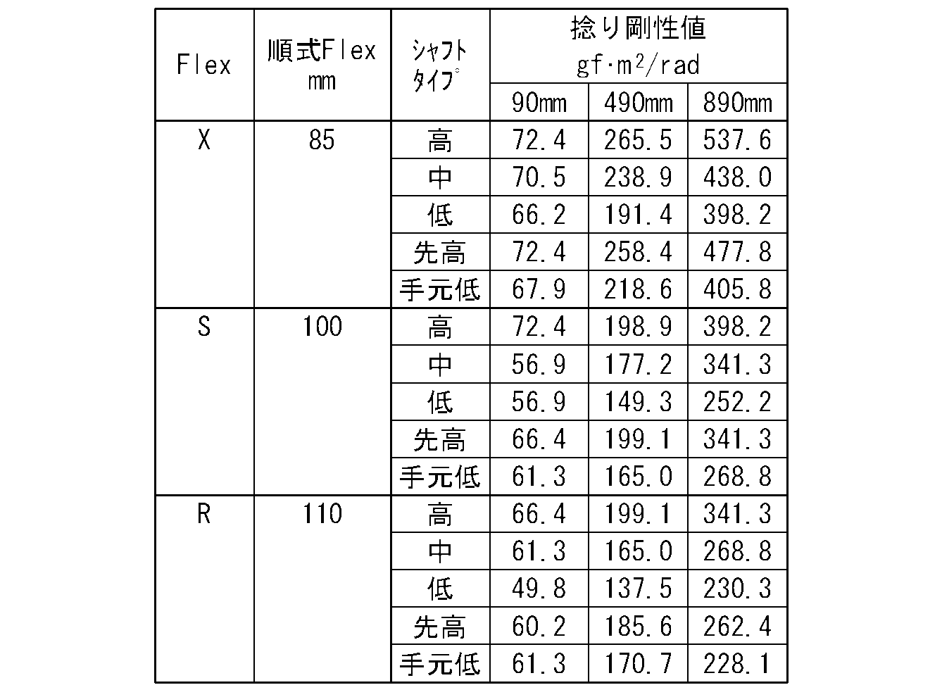
図1を参照しつつ説明した前記計測方法によりグリップ角速度を計測した。ボールとしてダンロップスポーツ株式会社製のSRIXON Z-STAR XVを用い、各クラブ(シャフト)について5球ずつ、合計25球の試打を行った。ただし、明らかなミスショットは除外し打ち直しを行った。
方向性は、打球の左右ばらつきの標準偏差σで評価し、最もσが小さいシャフトを方向性の良いシャフトとした。また、振り易さは、5種類のシャフトについてそれぞれ5球ずつ試打した後に、各テスターに最も振り易いシャフトを聞き取り調査により決定した。結果を表8に示す。
方向性は、打球の左右ばらつきの標準偏差σで評価し、最もσが小さいシャフトを方向性の良いシャフトとした。また、振り易さは、5種類のシャフトについてそれぞれ5球ずつ試打した後に、各テスターに最も振り易いシャフトを聞き取り調査により決定した。結果を表8に示す。

計測されたグリップ角速度のデータを用いて、前述した指標値(A)~(C)を計算した。この計算結果と、前記打球の左右ばらつきの標準偏差σで評価した最も方向性の良いシャフト捻り剛性とを表9~10に示す。また、同じく計算結果と、聞き取り調査により決定した、最も振り易いシャフト捻り剛性とを表11~12に示す。表9及び表11は、他の指標値による層別化をしておらず、表10及び表12は、他の指標値による層別化をしている。表10は、指標値(B)が20以上の場合と、20未満の場合とで層別化している。表12は、指標値(C)が-500以下の場合と、-500より大きい場合とで層別化している。
また、図21、23及び25は、表9に対応しており、それぞれシャフト先端部位(90mm)、シャフト中間部位(490mm)及びシャフト後端部位(890mm)について方向性の良いシャフト捻り剛性と指標値(A)との関係例を示しており、データの層別化がされていない。一方、図22、24及び26は、表10に対応しており、それぞれシャフト先端部位(90mm)、シャフト中間部位(490mm)及びシャフト後端部位(890mm)について方向性の良いシャフト捻り剛性と指標値(A)との関係例を示しており、指標値(B)によりデータの層別化がされている。
また、図27、29及び31は、表11に対応しており、それぞれシャフト先端部位(90mm)、シャフト中間部位(490mm)及びシャフト後端部位(890mm)について振り易いシャフト捻り剛性と指標値(B)との関係例を示しており、データの層別化がされていない。一方、図28、30及び32は、表12に対応しており、それぞれシャフト先端部位(90mm)、シャフト中間部位(490mm)及びシャフト後端部位(890mm)について振り易いシャフト捻り剛性と指標値(B)との関係例を示しており、指標値(C)によりデータの層別化がなされている。
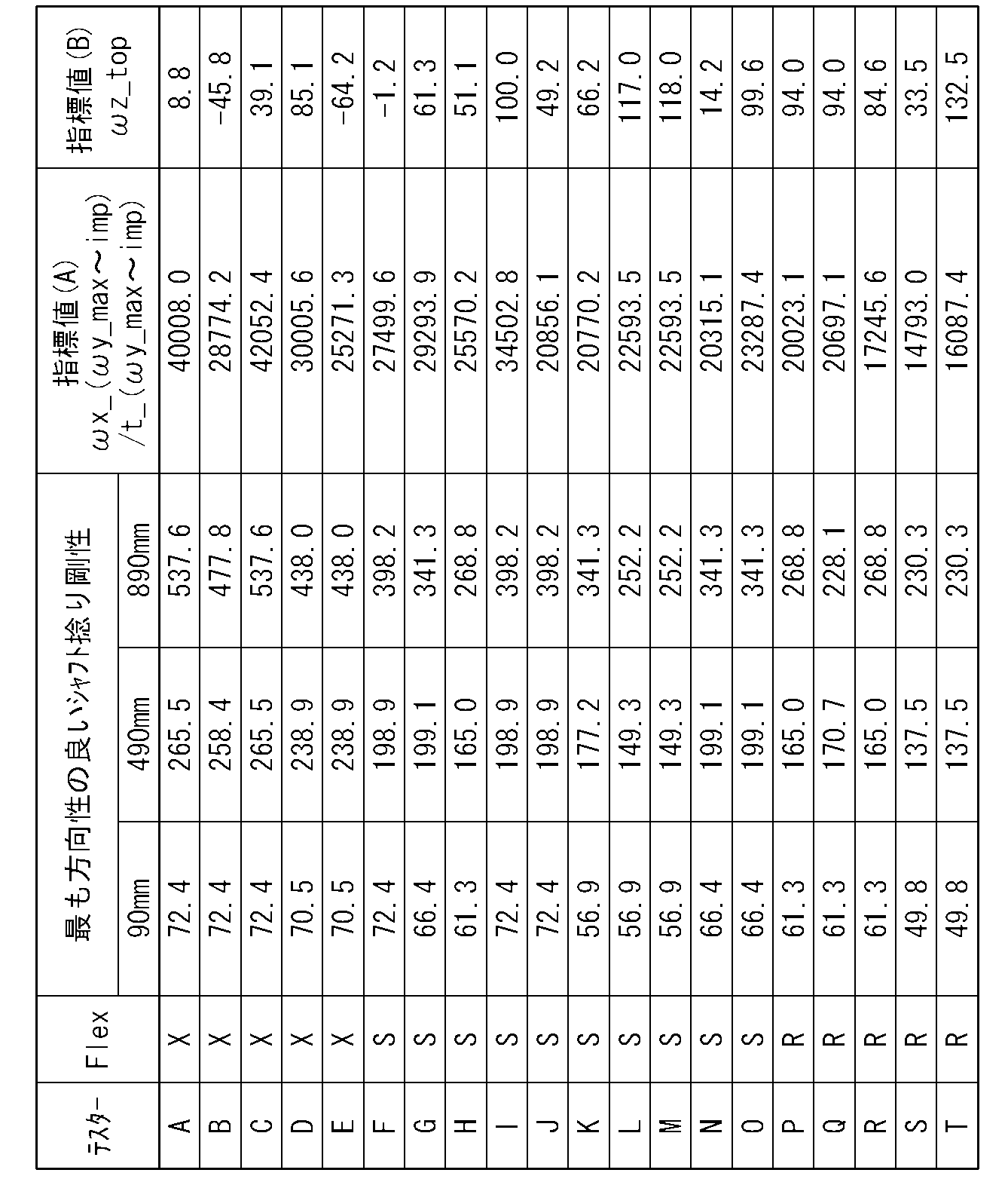
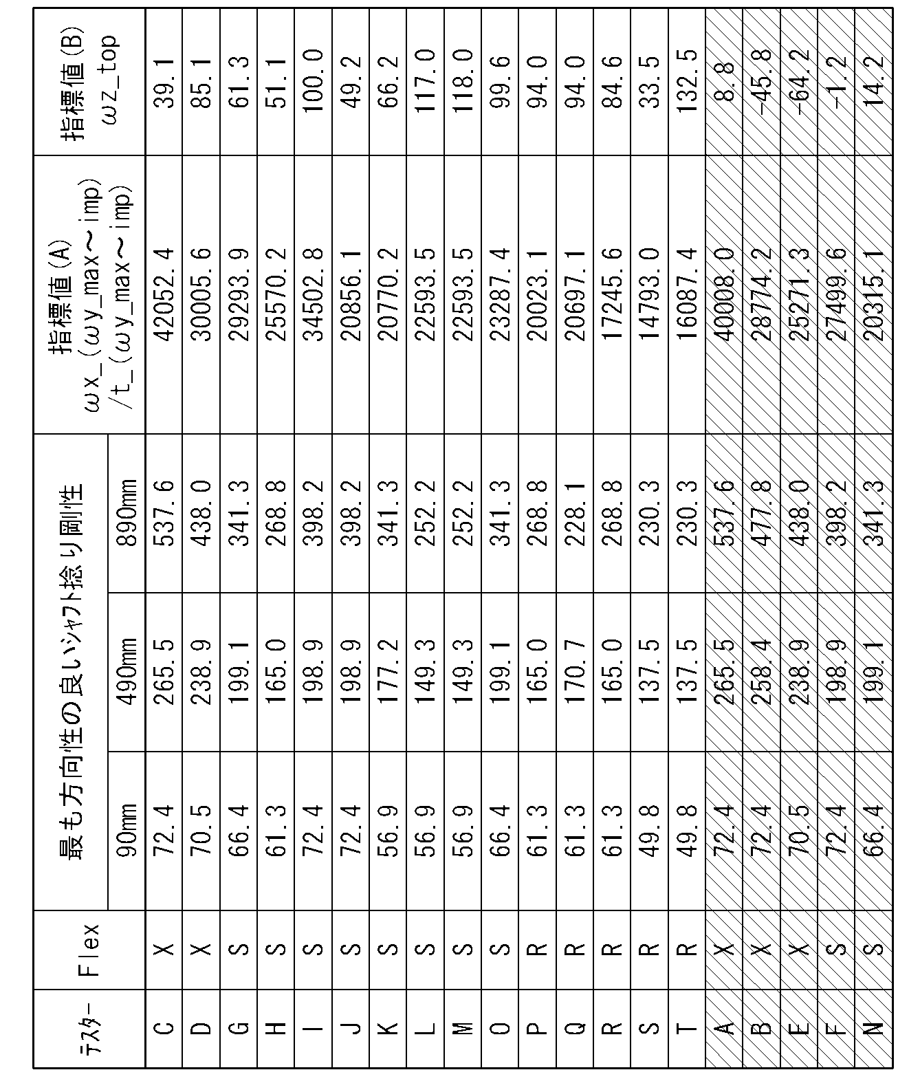


〔フィッティング方法〕
打球の方向性の良さに着目してフィッティングを行う場合、フィッティングを希望するゴルファーの実際のスイングから得られる指標値と、前記式(7)~(9)または式(10)~(15)とから、当該ゴルファーに適した捻り剛性値をシャフトの3つの部位(先端部位、中間部位および後端部位)について算出する。ついで、これら3つの捻り剛性値に最も近い捻り剛性を有するシャフトを複数のシャフトの中から選定する。これら複数のシャフトは、いずれも前記3つの部位における捻り剛性値が予め計測され、データベースに記憶されている。例えば、各部位についての、算出された捻り剛性値とデータベースに記憶されている捻り剛性値との差の和が最も小さくなるシャフトを当該ゴルファーにマッチするシャフトとして選定することができる。振り易さに着目する場合も同様にしてフィッティングを行うことができる。
打球の方向性の良さに着目してフィッティングを行う場合、フィッティングを希望するゴルファーの実際のスイングから得られる指標値と、前記式(7)~(9)または式(10)~(15)とから、当該ゴルファーに適した捻り剛性値をシャフトの3つの部位(先端部位、中間部位および後端部位)について算出する。ついで、これら3つの捻り剛性値に最も近い捻り剛性を有するシャフトを複数のシャフトの中から選定する。これら複数のシャフトは、いずれも前記3つの部位における捻り剛性値が予め計測され、データベースに記憶されている。例えば、各部位についての、算出された捻り剛性値とデータベースに記憶されている捻り剛性値との差の和が最も小さくなるシャフトを当該ゴルファーにマッチするシャフトとして選定することができる。振り易さに着目する場合も同様にしてフィッティングを行うことができる。
1 ゴルフクラブ
2 センサ
10 コンピュータ
11 シャフト
B ボール
G ゴルファー
2 センサ
10 コンピュータ
11 シャフト
B ボール
G ゴルファー
Claims (19)
- ゴルファーのスイングに基づいて当該ゴルファーにマッチしたトルクを有するシャフトを選定する、ゴルフクラブのシャフトのフィッティング方法であって、
3軸回りの角速度を計測可能なセンサがグリップに取り付けられたゴルフクラブでゴルフボールを打撃して前記センサの計測値を得る工程と、
前記計測値から定量化される前記角速度についての所定の指標値を得る工程と、
予め試打により作成された、前記指標値とシャフトのトルクとの関係に基づいて、予めトルクが測定された複数のシャフトの中からゴルファーにマッチしたシャフトを選定する工程と
を含むことを特徴とする、ゴルフクラブのシャフトのフィッティング方法。 - 前記センサがグリップエンドに装着されている、請求項1に記載のゴルフクラブのシャフトのフィッティング方法。
- x軸をゴルフクラブヘッドのトウーヒール方向に沿う方向に配向し、y軸を打球方向に沿うように配向し、z軸をシャフトの軸方向に一致するように配向したときに、
前記計測値からスイングにおけるアドレス、トップ及びインパクトを決定する工程、
ダウンスイング途中であってy軸のグリップ角速度が最大となるときからインパクトまでの時間であるt_ωy_max~impを計算する工程、
前記グリップ角速度が最大となるときからインパクトまでのx軸回りのグリップ角速度の平均値であるωx_ωy_max~impを計算する工程、
計算されたωx_ωy_max~impをt_ωy_max~impで除すことで、前記指標値としての、x軸回りの単位時間あたりのグリップ角速度変化量の大きさを計算する工程、及び
予め試打により用意された、前記x軸回りのグリップ角速度変化量の大きさとシャフトのトルクとの関係を示す近似式を用いて、前記計算されたx軸回りの単位時間あたりのグリップ角速度変化量の大きさからトルクを計算する工程
を含む、請求項1又は2に記載のゴルフクラブのシャフトのフィッティング方法。 - 前記トルクを計算する工程において用いられる前記近似式として、トップ付近でのz軸回りのグリップ角速度の変化量であるωz_topの大きさに応じて用意された複数の近似式のうちの一つを用いる、請求項3に記載のゴルフクラブのシャフトのフィッティング方法。
- 前記複数の近似式のうち、前記ωz_topが20(deg/s)以上の場合に第1近似式を用い、20(deg/s)未満の場合に第2近似式を用いる、請求項4に記載のゴルフクラブのシャフトのフィッティング方法。
- x軸をゴルフクラブヘッドのトウーヒール方向に沿う方向に配向し、y軸を打球方向に沿うように配向し、z軸をシャフトの軸方向に一致するように配向したときに、
前記計測値からスイングにおけるアドレス、トップ及びインパクトを決定する工程、
前記指標値として、トップ付近でのz軸回りのグリップ角速度の変化量であるωz_topを計算する工程、及び
予め試打により用意された、前記z軸回りのグリップ角速度の変化量とシャフトのトルクとの関係を示す近似式を用いて、前記計算されたz軸回りのグリップ角速度の変化量からトルクを計算する工程
を含む、請求項1又は2に記載のゴルフクラブのシャフトのフィッティング方法。 - 前記トルクを計算する工程において用いられる前記近似式として、トップからダウンスイング途中であってy軸のグリップ角速度が最大となるときまでのz軸回りのグリップ角速度変化量の大きさに応じて用意された複数の近似式のうちの一つを用い、
前記z軸回りのグリップ角速度変化量の大きさが、トップからダウンスイング途中であってy軸のグリップ角速度が最大となるときまでのz軸回りのグリップ角速度の平均値であるωz_top~ωy_maxを、トップからダウンスイング途中であってy軸のグリップ角速度が最大となるときまでの時間であるt_top~ωy_maxで除した値である、請求項6に記載のゴルフクラブのシャフトのフィッティング方法。 - 前記複数の近似式のうち、前記除した値であるωz_top~ωy_max/t_top~ωy_maxが-500(deg/s2)以下の場合に第3近似式を用い、-500(deg/s2)より大きい場合に第4近似式を用いる、請求項7に記載のゴルフクラブのシャフトのフィッティング方法。
- ゴルファーのスイングに基づいて当該ゴルファーにマッチした捻り剛性を有するシャフトを選定する、ゴルフクラブのシャフトのフィッティング方法であって、
3軸回りの角速度を計測可能なセンサがグリップに取り付けられたゴルフクラブでゴルフボールを打撃して前記センサの計測値を得る工程と、
前記計測値から定量化される前記角速度についての所定の指標値を得る工程と、
予め試打により作成された、前記指標値とシャフトの捻り剛性との関係に基づいて、予め捻り剛性が測定された複数のシャフトの中からゴルファーにマッチしたシャフトを選定する工程と
を含んでおり、
前記関係は、シャフトの軸方向の複数の部位について部位毎に作成されており、前記複数のシャフトは、当該部位毎の捻り剛性が測定されていることを特徴とする、ゴルフクラブのシャフトのフィッティング方法。 - 前記複数の部位は、シャフトの先端部位、中間部位および後端部位の3つの部位である、請求項9に記載のゴルフクラブのシャフトのフィッティング方法。
- 前記先端部位はシャフトの先端から50~150mmの間の部位であり、前記中間部位はシャフトの先端から400~600mmの間の部位であり、前記後端部位はシャフトの先端から800~1000mmの間の部位である、請求項10に記載のゴルフクラブのシャフトのフィッティング方法。
- 前記先端部位はシャフトの先端から90mmの部位であり、前記中間部位はシャフトの先端から490mmの部位であり、前記後端部位はシャフトの先端から890mmの部位である、請求項11に記載のゴルフクラブのシャフトのフィッティング方法。
- 前記センサがグリップエンドに装着されている、請求項9~12のいずれか一項に記載のゴルフクラブのシャフトのフィッティング方法。
- 前記センサのx軸をゴルフクラブヘッドのトウーヒール方向に沿う方向に配向し、前記センサのy軸を打球方向に沿うように配向し、前記センサのz軸をシャフトの軸方向に一致するように配向したときに、
前記計測値からスイングにおけるアドレス、トップ及びインパクトを決定する工程、
ダウンスイング途中であってy軸回りのグリップ角速度が最大となるときからインパクトまでの時間であるt_ωy_max~impを計算する工程、
前記グリップ角速度が最大となるときからインパクトまでのx軸回りのグリップ角速度の平均値であるωx_ωy_max~impを計算する工程、
計算されたωx_ωy_max~impをt_ωy_max~impで除すことで、前記指標値としての、x軸回りの単位時間あたりのグリップ角速度変化量の大きさを計算する工程、及び
前記複数の部位について予め試打により用意された、前記x軸回りのグリップ角速度変化量の大きさとシャフトの捻り剛性との関係を示す近似式を用いて、前記計算されたx軸回りの単位時間あたりのグリップ角速度変化量の大きさから各部位の捻り剛性を計算する工程
を含む、請求項9~13のいずれか一項に記載のゴルフクラブのシャフトのフィッティング方法。 - 前記捻り剛性を計算する工程において用いられる前記近似式として、トップ付近でのz軸回りのグリップ角速度の変化量であるωz_topの大きさに応じて用意された複数の近似式のうちの一つを用いる、請求項14に記載のゴルフクラブのシャフトのフィッティング方法。
- 前記複数の近似式のうち、前記ωz_topが20(deg/s)以上の場合に第5近似式を用い、20(deg/s)未満の場合に第6近似式を用いる、請求項7に記載のゴルフクラブのシャフトのフィッティング方法。
- 前記センサのx軸をゴルフクラブヘッドのトウーヒール方向に沿う方向に配向し、前記センサのy軸を打球方向に沿うように配向し、前記センサのz軸をシャフトの軸方向に一致するように配向したときに、
前記計測値からスイングにおけるアドレス、トップ及びインパクトを決定する工程、
前記指標値として、トップ付近でのz軸回りのグリップ角速度の変化量であるωz_topを計算する工程、及び
前記複数の部位について予め試打により用意された、前記z軸回りのグリップ角速度の変化量とシャフトの捻り剛性との関係を示す近似式を用いて、前記計算されたz軸回りのグリップ角速度の変化量から各部位の捻り剛性を計算する工程
を含む、請求項9~13のいずれか一項に記載のゴルフクラブのシャフトのフィッティング方法。 - 前記捻り剛性を計算する工程において用いられる前記近似式として、トップからダウンスイング途中であってy軸回りのグリップ角速度が最大となるときまでのz軸回りのグリップ角速度変化量の大きさに応じて用意された複数の近似式のうちの一つを用い、
前記z軸回りのグリップ角速度変化量の大きさが、トップからダウンスイング途中であってy軸回りのグリップ角速度が最大となるときまでのz軸回りのグリップ角速度の平均値であるωz_top~ωy_maxを、トップからダウンスイング途中であってy軸回りのグリップ角速度が最大となるときまでの時間であるt_top~ωy_maxで除した値である、請求項17に記載のゴルフクラブのシャフトのフィッティング方法。 - 前記複数の近似式のうち、前記除した値であるωz_top~ωy_max/t_top~ωy_maxが-500(deg/s2)より大きい場合に第7近似式を用い、-500(deg/s2)以下の場合に第8近似式を用いる、請求項18に記載のゴルフクラブのシャフトのフィッティング方法。
Priority Applications (1)
| Application Number | Priority Date | Filing Date | Title |
|---|---|---|---|
| US14/430,601 US9630066B2 (en) | 2012-09-25 | 2013-09-24 | Golf club shaft fitting method |
Applications Claiming Priority (4)
| Application Number | Priority Date | Filing Date | Title |
|---|---|---|---|
| JP2012211149A JP6152255B2 (ja) | 2012-09-25 | 2012-09-25 | ゴルフクラブのシャフトのフィッティング方法 |
| JP2012-211149 | 2012-09-25 | ||
| JP2013090791A JP6153373B2 (ja) | 2013-04-23 | 2013-04-23 | ゴルフクラブのシャフトのフィッティング方法 |
| JP2013-090791 | 2013-04-23 |
Publications (1)
| Publication Number | Publication Date |
|---|---|
| WO2014050801A1 true WO2014050801A1 (ja) | 2014-04-03 |
Family
ID=50388200
Family Applications (1)
| Application Number | Title | Priority Date | Filing Date |
|---|---|---|---|
| PCT/JP2013/075671 Ceased WO2014050801A1 (ja) | 2012-09-25 | 2013-09-24 | ゴルフクラブのシャフトのフィッティング方法 |
Country Status (2)
| Country | Link |
|---|---|
| US (1) | US9630066B2 (ja) |
| WO (1) | WO2014050801A1 (ja) |
Families Citing this family (7)
| Publication number | Priority date | Publication date | Assignee | Title |
|---|---|---|---|---|
| US9950237B2 (en) | 2015-04-23 | 2018-04-24 | Dunlop Sports Co., Ltd. | System, method, and apparatus for monitoring sporting apparatus and users thereof |
| JP2017131580A (ja) * | 2016-01-29 | 2017-08-03 | ヤマハ株式会社 | ゴルフクラブ |
| US10159885B2 (en) * | 2016-05-02 | 2018-12-25 | Nike, Inc. | Swing analysis system using angular rate and linear acceleration sensors |
| US10137347B2 (en) | 2016-05-02 | 2018-11-27 | Nike, Inc. | Golf clubs and golf club heads having a sensor |
| US10220285B2 (en) | 2016-05-02 | 2019-03-05 | Nike, Inc. | Golf clubs and golf club heads having a sensor |
| JP6981735B2 (ja) | 2016-06-12 | 2021-12-17 | 住友ゴム工業株式会社 | Gui表示装置 |
| EP4046696A1 (en) * | 2019-11-22 | 2022-08-24 | Kyocera Corporation | Sensor device and sports implement |
Citations (4)
| Publication number | Priority date | Publication date | Assignee | Title |
|---|---|---|---|---|
| JPH10244023A (ja) * | 1997-03-07 | 1998-09-14 | Nippon Shaft Kk | ゴルフスイング解析装置、その解析方法およびゴルフクラブ |
| JP2001070482A (ja) * | 1999-08-31 | 2001-03-21 | Mizuno Corp | ゴルファに最適なトルクのシャフト選定装置 |
| US6702692B1 (en) * | 1996-05-29 | 2004-03-09 | Earl F. Smith | Precise fit golf club fitting system and golf shaft selection method and apparatus |
| JP2005021329A (ja) * | 2003-07-01 | 2005-01-27 | Mizuno Corp | ゴルフクラブ選定装置、ゴルフクラブ選定方法、およびゴルフ用グラブ |
Family Cites Families (12)
| Publication number | Priority date | Publication date | Assignee | Title |
|---|---|---|---|---|
| JP2946331B1 (ja) * | 1998-09-07 | 1999-09-06 | 日本シャフト株式会社 | ゴルフクラブシャフト |
| US6638175B2 (en) * | 1999-05-12 | 2003-10-28 | Callaway Golf Company | Diagnostic golf club system |
| US7736242B2 (en) * | 2004-03-23 | 2010-06-15 | Nike, Inc. | System for determining performance characteristics of a golf swing |
| JP4672489B2 (ja) * | 2005-08-31 | 2011-04-20 | Sriスポーツ株式会社 | ゴルフクラブ |
| JP4388567B2 (ja) * | 2007-06-26 | 2009-12-24 | 学校法人 関西大学 | ゴルフクラブ解析方法 |
| JP5260151B2 (ja) * | 2008-06-05 | 2013-08-14 | ブリヂストンスポーツ株式会社 | ゴルフクラブ用シャフト及びそれを備えたゴルフクラブ |
| JP5248537B2 (ja) | 2009-05-21 | 2013-07-31 | エムアールシーコンポジットプロダクツ株式会社 | ゴルフシャフト設計装置及びゴルフシャフト設計プログラム |
| US8337336B2 (en) * | 2009-11-12 | 2012-12-25 | Sri Sports Limited | Shaft fitting system |
| US9186547B2 (en) * | 2011-04-28 | 2015-11-17 | Nike, Inc. | Golf clubs and golf club heads |
| US8821306B2 (en) * | 2011-05-27 | 2014-09-02 | Acushnet Company | Fitting system for a golf club |
| JP2013056074A (ja) * | 2011-09-09 | 2013-03-28 | Sumitomo Rubber Ind Ltd | スイング分析方法 |
| KR101398778B1 (ko) * | 2012-03-30 | 2014-05-27 | 스미토모 고무 고교 가부시키가이샤 | 골프 클럽의 샤프트의 피팅 방법 |
-
2013
- 2013-09-24 US US14/430,601 patent/US9630066B2/en active Active
- 2013-09-24 WO PCT/JP2013/075671 patent/WO2014050801A1/ja not_active Ceased
Patent Citations (4)
| Publication number | Priority date | Publication date | Assignee | Title |
|---|---|---|---|---|
| US6702692B1 (en) * | 1996-05-29 | 2004-03-09 | Earl F. Smith | Precise fit golf club fitting system and golf shaft selection method and apparatus |
| JPH10244023A (ja) * | 1997-03-07 | 1998-09-14 | Nippon Shaft Kk | ゴルフスイング解析装置、その解析方法およびゴルフクラブ |
| JP2001070482A (ja) * | 1999-08-31 | 2001-03-21 | Mizuno Corp | ゴルファに最適なトルクのシャフト選定装置 |
| JP2005021329A (ja) * | 2003-07-01 | 2005-01-27 | Mizuno Corp | ゴルフクラブ選定装置、ゴルフクラブ選定方法、およびゴルフ用グラブ |
Also Published As
| Publication number | Publication date |
|---|---|
| US20150224371A1 (en) | 2015-08-13 |
| US9630066B2 (en) | 2017-04-25 |
Similar Documents
| Publication | Publication Date | Title |
|---|---|---|
| US10478689B2 (en) | Method, system, and apparatus for analyzing a sporting apparatus | |
| US8801533B2 (en) | Golf clubs and golf club heads having digital lie and/or other angle measuring equipment | |
| JP6144538B2 (ja) | 選択支援装置及び選択支援方法 | |
| US9022878B2 (en) | Method and system for matching golf clubs to a specific user | |
| US9630066B2 (en) | Golf club shaft fitting method | |
| EP2962741B1 (en) | Golf implement fitting system and golf implement fitting program | |
| JP2013056074A (ja) | スイング分析方法 | |
| JP6911298B2 (ja) | ゴルフクラブのフィッティング装置、方法及びプログラム | |
| CN103372287A (zh) | 高尔夫球杆 | |
| EP3299069A1 (en) | Golf gear fitting system, golf gear fitting method, golf gear fitting program, golf swing classification method, golf shaft fitting system, golf shaft fitting method, and golf shaft fitting program | |
| KR20130111382A (ko) | 골프 클럽의 샤프트의 피팅 방법 | |
| US20170232309A1 (en) | Golf club head customization | |
| JP5981195B2 (ja) | ゴルフクラブのシャフトのフィッティング方法 | |
| JP6152255B2 (ja) | ゴルフクラブのシャフトのフィッティング方法 | |
| JP6488126B2 (ja) | ゴルフクラブのフィッティング装置、方法及びプログラム | |
| JP6153373B2 (ja) | ゴルフクラブのシャフトのフィッティング方法 | |
| JP6162398B2 (ja) | ゴルフクラブのシャフトの分析表示装置、及び分析表示プログラム | |
| US11819749B2 (en) | Golf club fitting apparatus | |
| JP2021058301A (ja) | ゴルフクラブのフィッティング装置 | |
| JP2021058304A (ja) | ゴルフクラブのフィッティング装置 | |
| JP7749939B2 (ja) | ゴルフクラブのフィッティング装置 | |
| JP7729234B2 (ja) | ゴルフクラブのシャフトのフィッティング装置 | |
| JP5953115B2 (ja) | ゴルフクラブのシャフトのフィッティング方法 | |
| WO2025126527A1 (ja) | ゴルフクラブヘッドのフィッティング装置、フィッティング方法及びフィッティングプログラム | |
| JP6397959B2 (ja) | スイング分析方法 |
Legal Events
| Date | Code | Title | Description |
|---|---|---|---|
| 121 | Ep: the epo has been informed by wipo that ep was designated in this application |
Ref document number: 13842791 Country of ref document: EP Kind code of ref document: A1 |
|
| WWE | Wipo information: entry into national phase |
Ref document number: 14430601 Country of ref document: US |
|
| NENP | Non-entry into the national phase |
Ref country code: DE |
|
| 122 | Ep: pct application non-entry in european phase |
Ref document number: 13842791 Country of ref document: EP Kind code of ref document: A1 |