WO2014050416A1 - 光コネクタ用のプラグ、光コネクタ用のジャック、および光コネクタ - Google Patents
光コネクタ用のプラグ、光コネクタ用のジャック、および光コネクタ Download PDFInfo
- Publication number
- WO2014050416A1 WO2014050416A1 PCT/JP2013/073037 JP2013073037W WO2014050416A1 WO 2014050416 A1 WO2014050416 A1 WO 2014050416A1 JP 2013073037 W JP2013073037 W JP 2013073037W WO 2014050416 A1 WO2014050416 A1 WO 2014050416A1
- Authority
- WO
- WIPO (PCT)
- Prior art keywords
- plug
- jack
- optical
- optical coupling
- coupling portion
- Prior art date
- Legal status (The legal status is an assumption and is not a legal conclusion. Google has not performed a legal analysis and makes no representation as to the accuracy of the status listed.)
- Ceased
Links
Images
















Classifications
-
- G—PHYSICS
- G02—OPTICS
- G02B—OPTICAL ELEMENTS, SYSTEMS OR APPARATUS
- G02B6/00—Light guides; Structural details of arrangements comprising light guides and other optical elements, e.g. couplings
- G02B6/24—Coupling light guides
- G02B6/36—Mechanical coupling means
- G02B6/38—Mechanical coupling means having fibre to fibre mating means
-
- G—PHYSICS
- G02—OPTICS
- G02B—OPTICAL ELEMENTS, SYSTEMS OR APPARATUS
- G02B6/00—Light guides; Structural details of arrangements comprising light guides and other optical elements, e.g. couplings
- G02B6/24—Coupling light guides
- G02B6/36—Mechanical coupling means
- G02B6/38—Mechanical coupling means having fibre to fibre mating means
- G02B6/3807—Dismountable connectors, i.e. comprising plugs
- G02B6/3833—Details of mounting fibres in ferrules; Assembly methods; Manufacture
- G02B6/3847—Details of mounting fibres in ferrules; Assembly methods; Manufacture with means preventing fibre end damage, e.g. recessed fibre surfaces
- G02B6/3849—Details of mounting fibres in ferrules; Assembly methods; Manufacture with means preventing fibre end damage, e.g. recessed fibre surfaces using mechanical protective elements, e.g. caps, hoods, sealing membranes
-
- G—PHYSICS
- G02—OPTICS
- G02B—OPTICAL ELEMENTS, SYSTEMS OR APPARATUS
- G02B6/00—Light guides; Structural details of arrangements comprising light guides and other optical elements, e.g. couplings
- G02B6/24—Coupling light guides
- G02B6/36—Mechanical coupling means
- G02B6/38—Mechanical coupling means having fibre to fibre mating means
- G02B6/3807—Dismountable connectors, i.e. comprising plugs
- G02B6/3869—Mounting ferrules to connector body, i.e. plugs
-
- G—PHYSICS
- G02—OPTICS
- G02B—OPTICAL ELEMENTS, SYSTEMS OR APPARATUS
- G02B6/00—Light guides; Structural details of arrangements comprising light guides and other optical elements, e.g. couplings
- G02B6/24—Coupling light guides
- G02B6/26—Optical coupling means
- G02B6/32—Optical coupling means having lens focusing means positioned between opposed fibre ends
-
- G—PHYSICS
- G02—OPTICS
- G02B—OPTICAL ELEMENTS, SYSTEMS OR APPARATUS
- G02B6/00—Light guides; Structural details of arrangements comprising light guides and other optical elements, e.g. couplings
- G02B6/24—Coupling light guides
- G02B6/36—Mechanical coupling means
- G02B6/38—Mechanical coupling means having fibre to fibre mating means
- G02B6/3807—Dismountable connectors, i.e. comprising plugs
- G02B6/381—Dismountable connectors, i.e. comprising plugs of the ferrule type, e.g. fibre ends embedded in ferrules, connecting a pair of fibres
-
- G—PHYSICS
- G02—OPTICS
- G02B—OPTICAL ELEMENTS, SYSTEMS OR APPARATUS
- G02B6/00—Light guides; Structural details of arrangements comprising light guides and other optical elements, e.g. couplings
- G02B6/24—Coupling light guides
- G02B6/36—Mechanical coupling means
- G02B6/38—Mechanical coupling means having fibre to fibre mating means
- G02B6/3807—Dismountable connectors, i.e. comprising plugs
- G02B6/381—Dismountable connectors, i.e. comprising plugs of the ferrule type, e.g. fibre ends embedded in ferrules, connecting a pair of fibres
- G02B6/3826—Dismountable connectors, i.e. comprising plugs of the ferrule type, e.g. fibre ends embedded in ferrules, connecting a pair of fibres characterised by form or shape
- G02B6/3829—Bent or angled connectors
Definitions
- the present invention relates to a technology of a plug jack type optical connector.
- Patent Document 1 when a plug is inserted into an optical jack (jack) and fitted, an optical element incorporated in the distal end portion of the plug and the inner portion of the body (plug accommodating portion) of the optical jack that accommodates the plug. Discloses an optical connector facing each other. In other words, the optical transmission performed by the optical connector of Patent Document 1 is performed between the inner part of the plug housing part of the optical jack and the tip part of the plug inserted there.
- an optical connector of the present invention includes a plug and a jack for the optical connector.
- a plug-side optical coupling portion that optically couples light transmitted through the plug-side optical waveguide means held by the plug to the jack is disposed on a side surface of the plug.
- a jack-side optical coupling portion that optically couples light transmitted through the jack-side optical waveguide means held by the jack to the plug is disposed on the inner surface of the jack. Details will be described later.
- FIG. 3 is a cross-sectional view taken along line AA of FIG. 2, schematically showing a cross section when an example of a plug and a jack at the time of fitting is viewed from above.
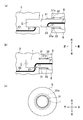
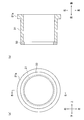
- FIG. 29 is a view of another example of a shutter provided in the plug, where (a) is a view seen from the front, and (b) is a cross-sectional view taken along the line BB of FIG. 28 (a).
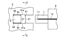
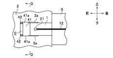
- FIG. 30 is an explanatory diagram of another example of a shutter provided in the jack, and corresponds to a cross-sectional view taken along the line CC of FIG. 29A.
- FIG. 31 It is a schematic diagram which shows an example of the airflow generation mechanism with which a jack is equipped, (a) respond
- FIG. 33 Is a schematic view of the plug and jack as viewed from the rear
- FIG. 33C is another example of the plug and jack of FIGS. 33A and 33B.
- FIG. 34 It is a schematic diagram which shows an example which combined the airflow generation mechanism with which a plug is provided, and the airflow generation mechanism with which a jack is provided, (a) corresponds to the figure which looked at the plug and jack after insertion from the upper part, and (b), It is a schematic diagram when the plug and jack of Fig.34 (a) at the time of a fitting are seen from back.
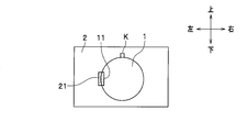
- an optical connector 100 of the present embodiment (hereinafter simply referred to as “optical connector”) includes a resin plug 1 having a substantially cylindrical outer shape and a jack 2 having a substantially rectangular parallelepiped outer shape.
- the plug 1 includes a head portion inserted into the jack 2, a support portion S, and a cable protection portion U.
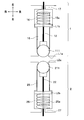
- Two lenses (optical coupling portions) 11a (11) and 11b (11) are provided on the side surface of the top portion of the plug 1, and a retaining groove R is formed.
- the lens 11 will be described later.
- a key K is formed on the support portion S.
- the jack 2 is formed with a plug accommodating portion C serving as a hole for accommodating the plug 1 to be fitted. In FIG. 1, the inlet of the plug housing portion C is illustrated.
- An optical fiber cable OC is connected to the left outer surface of the jack 2.
- the retaining groove R is a groove (engagement groove) formed in the vicinity of the tip of the plug 1 along the entire circumferential direction.
- a retaining engagement portion (not shown) provided near the inner portion of the plug housing portion C of the jack 2 is engaged with the retaining groove R at the time of fitting, unintentional disconnection of the plug 1 can be prevented.
- the above-described retaining engagement portion can be configured as a leaf spring that extends over substantially the entire circumferential direction of the plug housing portion C, for example.
- the support portion S is a member that is held by the user, and holds the main body of the plug 1 (components of the plug 1 other than the support portion S) and a cable extending rearward from the plug 1.
- the cable protection part U is fixed to the cable and restricts the support part S from moving backward.
- the key K is formed on the front end surface of the support portion S and has a shape that engages with the key groove H of the jack 2.
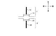
- optical coupling and optical fiber Referring to FIG. 3, lens 11 (plug-side optical coupling portion) provided in plug 1, optical fiber 12 (plug-side optical waveguide means), lens 21 provided in jack 2 (jack-side optical coupling portion), optical fiber 22 ( Jack side optical waveguide means) will be described.
- FIG. 3 only one lens 11 included in the plug 1 and one optical fiber 12 held by the plug 1 are illustrated. Further, only one lens 21 provided in the jack 2 and one optical fiber 22 held by the jack 2 are illustrated.
- the optical fibers 12 and 22 pass through holes formed in the plug 1 and the jack 2, respectively, and are fixed to the plug 1 and the jack 2 using an adhesive or the like.
- the lenses 11 and 21 optically couple light transmitted through the optical fiber 12 and light transmitted through the optical fiber 22 to each other.
- Optical coupling in the present embodiment means that light is transmitted through the optical coupling portion of the fitted plug and the optical coupling portion of the jack.
- the lens 11 efficiently couples light transmitted through the optical fiber 12 to the jack 2, and the lens 21 efficiently couples light transmitted through the optical fiber 22 to the plug 1.
- the function of optical coupling can be enhanced.
- Lenses 11 and 21 are respectively fixed to plug 1 and jack 2 using an adhesive or the like.
- the lenses 11 and 21 are preferably those that can make the transmitted light into collimated light.
- the outer surface of the lens 11 and the side surface of the plug 1 are flush with each other.
- the outer surface of the lens 21 and the inner side surface of the jack 2 are flush with each other.
- the end of the optical fiber 12 may be in contact with the lens 11 or may be arranged with a gap from the lens 11 so that light transmission is effectively realized.
- the optical fiber 12 extending in the front-rear direction inside the substantially cylindrical plug 1 is bent leftward, and the end of the optical fiber 12 is in contact with the lens 11.
- the end of the optical fiber 22 may be in contact with the lens 21 or may be disposed with a gap from the lens 21 so that light transmission is effectively realized.
- the optical fiber 22 is linearly arranged in the left-right direction inside the jack 2, but it may be bent as shown in FIG.
- the lens 11 is arranged on the side surface (left side surface in FIG. 3) of the plug 1.
- the lens 21 is disposed on the inner surface of the jack 2, and the position around the axis can be made to coincide with the lens 11 by the key K and the key groove H when fitted.
- positioned at a side surface is the biggest characteristic of this invention which is not in a prior art example.
- the positioning of the lens 11 and the lens 21 in the axial direction (front-rear direction) is performed by abutting the distal end portion of the plug 1 against the back portion of the plug housing portion C of the jack 2.
- the lens 21 is disposed on the inner surface of the jack 2 at a position away from the back of the jack 2. For this reason, it is arranged away from the back of the jack 2 where foreign matter is likely to accumulate, and the surface of the lens 21 is orthogonal to the plug insertion / removal direction (front-rear direction), which is the entry direction of foreign matter. Therefore, compared to the conventional example, the structure is such that foreign matter is less likely to accumulate and adhere to the lens surface when not fitted. On the other hand, at the time of fitting, the lens 11 is at a position away from the back of the jack 2, so that it is separated from the foreign matter accumulated in the back by a predetermined distance.
- the tip of the plug 1 pushes the foreign matter mixed in an arbitrary place in the plug accommodating portion C, so that the foreign matter is the lens 11, 21. Is separated by a predetermined distance.
- the possibility that the foreign object approaches the lenses 11 and 21 is low, and the possibility that the foreign object affects the light transmission performed by the optical connector can be greatly reduced.
- the plug 1 is removed from the jack 2. Accordingly, when the plug 1 is inserted and removed as in the conventional example, it is not necessary to clean the optical connector or attach / detach the protective cap, and even a user who does not have basic knowledge about the optical connector can easily handle it. Therefore, the optical connector can be easily introduced into a device such as a portable terminal that is used in an environment where there are many foreign matters such as dust and dust regardless of whether indoors or outdoors.
- the optical coupling part can take various forms. For example, as shown in FIG. 4, the outer surface of the lens 11 is located inside the side surface of the plug 1 to form a recess, and the outer surface of the lens 21 is located inside the inner surface of the jack 2 to form a recess. Also good. If optical coupling can be sufficiently realized, a gap may be formed between the lens 11 and the lens 21.
- the outer surface of the lens 11 is located outside the side surface of the plug 1 to form a convex portion
- the outer surface of the lens 21 is outside the inner side surface of the jack 2 (the side occupied by the plug housing portion C).
- a convex portion may be formed on the right side in FIG. According to such a configuration in which the lenses 11 and 21 protrude, the lenses 11 and 21 can be rubbed with each other at the time of fitting, and foreign matters attached to the lenses 11 and 21 can be reliably removed.
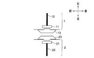
- the optical coupling portion of the plug 1 has a protection portion 13 (plug-side protection portion) that protects the lens 11, and the optical coupling portion of the jack 2 is a protection portion that protects the lens 21. 23 (jack side protection part).
- the protection parts 13 and 23 can reliably prevent the lenses 11 and 21 from being damaged.
- the protection parts 13 and 23 are respectively fixed to the plug 1 and the jack 2 using an adhesive or the like.
- the protection parts 13 and 23 can be made of a material that transmits light transmitted through the optical fibers 12 and 22 and preferably a material harder than the lens. By doing so, the optical coupling of the optical connector by the protection units 13 and 23 is not inhibited.
- the protective part 13 may be located outside the side surface of the plug 1 to form a convex part, and the protective part 23 may be located outside the inner side surface of the jack 2 to form a convex part. According to such a configuration in which the protective portions 13 and 23 protrude, the protective portions 13 and 23 can be rubbed with each other at the time of fitting, and foreign matters attached to the protective portions 13 and 23 can be reliably removed.
- a ball lens 111 as an optical coupling part provided in the plug 1 is arranged with a gap from an end of the optical fiber 12, and a ball lens 211 as an optical coupling part provided in the jack 2 is provided at the end of the optical fiber 22.
- positioned with the clearance gap between the part is illustrated.
- the ball lens 111 expands the propagation light diameter of the outgoing light from the core 121 of the optical fiber 12 to almost the diameter of the lens and makes it collimated light.
- the expanded collimated light is condensed on the core 221 of the optical fiber 22 by the ball lens 211.
- Such an increase in the propagation light diameter can ease the alignment accuracy when fitting the optical coupling portions. Moreover, even if a foreign substance adheres to the ball lens, it is possible to reduce the possibility that light transmission is blocked by the foreign substance.
- the distance between the optical fiber and the lens (ball lens), the focal length, and the shape of the lens are designed so that a desired propagation light diameter can be realized in consideration of the NA (Numerical Aperture) of the optical fiber. .
- an objective lens or the like may be used as a lens that generates collimated light.
- the lens 11 and the lens 21 are not provided, and the optical coupling portion can be configured only by the end portion of the optical fiber 12 and the end portion of the optical fiber 22.
- the end of the optical fiber 12 may be positioned inside the side surface of the plug 1 to form a recess, and the end of the optical fiber 22 may be positioned inside the inner surface of the jack 2 to form a recess.
- the end portion of the optical fiber 12 may be flush with the side surface of the plug 1, may protrude outward from the side surface of the plug 1, or may be positioned near the side surface of the plug 1.
- the end of the optical fiber 22 may be flush with the inner side surface of the jack 2, may protrude outward from the inner side surface of the jack 2, or may be located near the inner side surface of the jack 2.
- FIG. 9 shows an example of a specific configuration of the optical coupling unit.
- the optical coupling portion of the plug 1 includes a ball lens 111 (see FIG. 7), a pedestal portion 14, and two springs 15.
- the optical coupling portion of the jack 2 includes a ball lens 211 (see FIG. 7), a pedestal portion 24, and two springs 25.
- a ferrule 16 that holds the optical fiber 12 and is fixed to the plug 1 and a ferrule 26 that holds the optical fiber 22 and is fixed to the jack 2 are illustrated.
- the pedestal portion 14 supports the ball lens 111 in the left direction (vertical outer side in the front-rear direction, radially outer side of the plug 1) so that the rotation of the ball lens 111 is smooth.
- a hole 14a is formed in the central portion of the pedestal portion 14 along the left-right direction (vertical direction in the front-rear direction), and does not hinder optical coupling.
- the spring 15 is disposed between the ferrule 16 and the pedestal portion 14 and elastically supports the pedestal portion 14 in the left direction.
- a stopper (locking portion) L1 serving as a flange extending radially inward from the inner wall end of the hole formed for the optical fiber 12 is formed on the side surface of the plug 1.
- the stopper L1 locks the ball lens 111 from the left side (vertically outside in the front-rear direction) to prevent the ball lens 111 from popping out.
- a part of the ball lens 111 is exposed outside the side surface of the plug 1.
- the degree of exposure of the ball lens 111 changes according to the distance between the side surface of the plug 1 and the inner side surface of the jack 2 due to the biasing action of the spring 15.
- a part of the ball lens 111 is rubbed and rotated on the inner surface of the jack 2. Even when foreign matter is attached to the ball lens 111 due to the rotation of the ball lens 111, the foreign matter moves to the position of the stopper L1 and is consequently removed.
- Rotation of the ball lens 111 can be expected to remove not only foreign matter adhering to the ball lens 111 but also foreign matter present in the plug housing portion C. This is realized when the foreign matter existing in the plug housing portion C adheres to the ball lens 111 as the ball lens 111 rotates. Further, scratches on the surface of the ball lens 111 that may occur when the ball lens 111 is rubbed are dispersed without being concentrated on one place of the ball lens 111. As a result, deterioration of the optical transmission characteristics of the optical connector can be significantly suppressed. Even when the distance between the side surface of the plug 1 and the inner side surface of the jack 2 is very small, the spring 15 contracts, so that the pressure when the ball lens 111 contacts the jack 2 is reduced. For this reason, it is possible to avoid high pressure rubbing of the ball lens 111 which may cause a large scratch by inserting the plug 1 vigorously.
- the shape of the stopper L1 is not limited to the shape shown in FIG. 9, and may be a shape corresponding to the shape of the ball lens 111, for example. Further, the number of springs 15 may be one or three or more.
- the pedestal 24, the hole 24a, and the spring 25 constituting the optical coupling portion of the jack 2 are the same as the pedestal 14, the hole 14a, and the spring 15 of the optical coupling portion of the plug 1, and the optical coupling portion of the jack 2. Functions in the same manner as the optical coupling portion of the plug 1. Further, the stopper L2 of the jack 2 functions in the same manner as the stopper L1 of the plug 1. For this reason, the description regarding the jack 2 is abbreviate
- the optical coupling unit of FIG. 9 may be applied only to the jack 2, and the configuration of the optical coupling unit illustrated in FIGS. 4, 5, 6, and 7 may be employed for the plug 1.
- the optical coupling unit shown in FIG. 9 may be applied only to the plug 1, and the configuration of the optical coupling unit exemplified in FIGS. 4, 5, 6, and 7 may be employed for the jack 2. With such a configuration, there are advantages of downsizing and cost reduction.
- FIG. 10 shows another configuration example of the optical coupling unit shown in FIG.
- the optical coupling portion of the plug 1 includes a ball lens 111 and a spring 15a.
- the optical coupling portion of the jack 2 includes a ball lens 211 and a spring 25a.
- the spring 15a elastically supports the ferrule 16 in the left direction with a large gap from the ball lens 111 (than the thickness of the pedestal 14).
- a spring 15a is arranged between the stopper L1b that functions as a flange integrated with the ferrule 16 and the stopper 17 that functions as a flange by molding the main body of the plug 1, so that the ferrule 16 is elastically formed.
- the diameter of the spring 15a is larger than the diameter of the ferrule 16, and the end (indicated by a broken line) of the ferrule 16 is inserted into the spring 15a.
- the other end of the ferrule 16 supports the ball lens 111 in the left direction.
- the other end of the ferrule 16 has a curved surface that smoothens the rotation of the ball lens 111, and a hole is formed in the center thereof. At the back of the hole, the end of the optical fiber 12 exists.
- a stopper L1a that functions similarly to the stopper L1 in FIG. 9 is formed on the side surface of the plug 1.
- the stopper L1a has a curved surface that smoothens the rotation of the ball lens 111.
- the action of the spring 15a on the ball lens 111 is the same as the action of the spring 15 in FIG. Since the ferrule 16 is inside the spring 15a, when the spring 15a contracts, the ferrule 16 can move stably in the left-right direction.
- the stopper L1b moves rightward (vertically inward in the front-rear direction; radially inward of the plug 1), and the spring 15a contracts.
- the stopper L1b, the ferrule 16, and the ball lens 111 are moved to the left by the biasing action of the spring 15a, and a part of the ball lens 111 is exposed outside the side surface of the plug 1. To do.
- the distance between the ball lens 111 and the end of the optical fiber 12 can be maintained at a predetermined distance regardless of the contracted state of the spring 15a.
- the light emitted from the ball lens 111 can be always collimated light, and the light transmission characteristics can be stabilized.
- the shape of the stopper L1a is not limited to the shape shown in FIG. 10, and can take any shape so as to maintain the locking function.
- the spring 25a, the stopper L2b, the stopper 27, and the ferrule 26 of the jack 2 are the same as the spring 15a, the stopper L1b, the stopper 17, and the ferrule 16 of the plug 1, and the optical coupling portion of the jack 2 is the optical coupling of the plug 1. Functions in the same way as the section. Further, the stopper L2a of the jack 2 functions in the same manner as the stopper L1a of the plug 1. For this reason, the description regarding the jack 2 is abbreviate
- the optical coupling unit of FIG. 10 may be applied only to the jack 2, and the configuration of the optical coupling unit illustrated in FIGS. 4, 5, 6, and 7 may be employed for the plug 1.
- the optical coupling unit shown in FIG. 10 may be applied only to the plug 1 and the jack 2 may have the configuration of the optical coupling unit exemplified in FIGS. 4, 5, 6, and 7. With such a configuration, there are advantages of downsizing and cost reduction.
- the present invention can be applied to any shape of the plug 1 as long as the position of the plug 1 around the axis in the front-rear direction can be uniquely determined.
- the lens 11 is arranged on the side surface of the cylindrical plug 1 with the key K (see FIG. 1) described so far, and the inner surface of the jack 2 is fitted to the side surface when fitted.
- the lens 21 facing the lens 11 can be arranged.
- a lens 11 is arranged on one of the side faces of a trapezoidal square pillar-shaped plug 1, and the inner side face of the jack 2 that can be fitted with the plug 1
- the lens 21 facing the lens 11 can be arranged.
- the shape of the plug 1 is a columnar shape with an asymmetrical cross section. If the shape of the plug 1 is an asymmetrical columnar shape, the position around the axis in the front-rear direction of the plug 1 can be uniquely determined without using a key mechanism composed of the key K and the key groove H. .
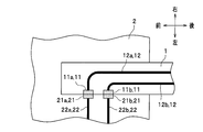
- the plug 1 and the jack 2 are provided with two systems of optical transmission paths composed of an optical fiber and an optical coupling unit.
- one of the optical transmission paths for example, the optical transmission path including the lens 11a (11) and the optical fiber 12a (12) of the plug 1 and the lens 21a (21) and the optical fiber 22a (22) of the jack 2 is connected to the plug 1.
- the other for example, an optical transmission path comprising the lens 11b (11) and optical fiber 12b (12) of the plug 1, the lens 21b (21) of the jack 2 and the optical fiber 22b (22)).
- the plug 1 can be used for transmission from jack 2 to plug 1. It is assumed that the plug 1 has a hexagonal column shape whose cross section is an asymmetrical hexagon. Further, even if there is only one optical transmission path introduced into the plug 1 and the jack 2 (see FIG. 3), single-core bidirectional optical transmission can be realized using WDM (Wavelength Division Multiplexing) technology or the like.
- WDM Widelength Division Multiplexing
- the lens 11 a is disposed on the right side surface of the plug 1
- the lens 11 b is disposed on the left side surface of the plug 1.
- Each of the lens 11b and the lens 21b is disposed at a position facing the lens 11a and the lens 11b.
- FIG. 14 shows a hexagonal shape in which the upper two corners of the square columnar plug 1 are cut out, and the jack 2 corresponds to this shape of the plug 1. Providing such a notch in the plug 1 prevents the user from erroneously inserting the plug 1 in the wrong direction such as upside down with respect to the jack 2. As a result, the opposing of the lens 11a and the lens 21a and the opposing of the lens 11b and the lens 21b can be ensured.
- two systems of optical transmission paths may be arranged on the left side surface of the plug 1.
- the optical transmission / reception device connected from the outside of the jack 2 may be disposed only on one side (for example, the left side) of the jack 2, and does not need to be disposed on the opposite side (for example, the right side).
- the occupied area in the left-right direction of the optical transmission / reception apparatus (not shown) to be provided at the tip (left side) of the optical fiber 22a and the optical fiber 22b can be almost halved, and the mounting space can be reduced.
- the configuration exemplified for the plug 1 with reference to FIGS. 13 to 15 can also be applied to the jack 2.
- optical path conversion unit An optical path conversion unit that converts an optical path of light transmitted from an optical fiber will be described. In this description, the configuration in which the plug 1 is provided with the optical path conversion unit will be described, but the configuration in which the jack 2 is provided with the optical path conversion unit can be similarly realized.
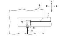
- an optical path conversion unit 18 is disposed inside the plug 1.
- the optical path conversion unit 18 is disposed between the end of the optical fiber 12 and the lens 11, converts the optical path of light transmitted from the end of the optical fiber 12, and transmits the light to the lens 11. Alternatively, the optical path of the light transmitted from the lens 11 is converted and the light is transmitted to the end of the optical fiber 12.
- the optical fiber 12 extends in parallel in the front-rear direction, and light transmitted forward from the end of the optical fiber 12 travels leftward by the optical path conversion unit 18 and is transmitted to the lens 11.
- the lens 11 performs optical coupling with the lens 21 on the transmitted light. A specific configuration of the optical path conversion unit 18 will be described later.
- optical path conversion unit 18 optical path conversion can be performed without bending the optical fiber 12 as shown in FIG. 3, and optical coupling between the lens 11 and the lens 21 can be realized.
- the entire plug 1 can be reduced in size. This also applies to the jack 2, so that the entire optical connector can be reduced in size.
- the efficiency of light transmission is maximized.
- the design in which the aforementioned angle is vertical simplifies the manufacture of the optical connector. Therefore, it is preferable to arrange the optical path changing unit 18 so that the efficiency of optical transmission is maximized.
- priority should be given to the suppression of the reflected light at the optical coupling portion, there is no need to make it vertical.
- the optical path conversion unit can take various forms.
- the optical path changing unit 18 can be configured using a mirror 18a and an optical fiber 18b.
- the mirror 18a is arranged at an angle of 45 ° on the left side with respect to the front-rear direction. Therefore, the mirror 18a reflects light transmitted in the forward direction from the end of the optical fiber 12 extending in the front-rear direction, and transmits the light in the left direction.
- the optical fiber 18b is made of the same material as the optical fiber 12, for example, and extends in the left-right direction. One end of the optical fiber 18 b is connected to the lens 11. The light reflected by the mirror 18a is transmitted into the other end of the optical fiber 18b. The light transmitted through the optical fiber 18 b is optically coupled by the lens 11 and the lens 21.
- the optical waveguide can be formed from a plastic molding material such as ULTEM (registered trademark).
- the optical waveguide has an inclined surface 18c that forms an angle of 45 ° on the left side with respect to the front-rear direction.
- the inclined surface 18c is mirror-coated (indicated by a thick line). Therefore, the inclined surface 18c functions similarly to the mirror 18a of FIG.
- the optical path changing unit 18 in FIG. 18 is preferably formed integrally with the main body of the plug 1 or the lens 11.
- an optical path conversion unit that also functions as an optical coupling unit is illustrated as a molded part F.
- the molded part F is made of a plastic molding material such as ULTEM.
- the molded part F is accommodated in a hole provided in the main body of the plug 1.
- a part of the surface of the molded part F is in contact with a part of the surface of the hole of the plug 1, so that it is accommodated in the hole of the plug 1.
- the molded part F cannot be rotated and the positioning of the molded part F is ensured.
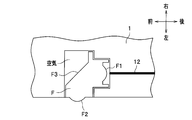
- the molded part F includes a lens F1, a lens F2, and an inclined surface F3.
- the lens F ⁇ b> 1 faces the end of the optical fiber 12 and condenses light transmitted from the optical fiber 12.
- the lens F2 faces the optical coupling portion (not shown) of the jack 2 and performs optical coupling.
- the inclined surface F3 forms an angle of 45 ° on the left side with respect to the front-rear direction. The light transmitted forward through the lens F1 is reflected leftward by the inclined surface F3 and reaches the lens F2.
- the refractive index of the molded part F made of ULTEM is about 1.6. Further, the gap between the molded part F and the above-described hole of the plug 1 is made of air. For this reason, the reflection by the inclined surface F3 becomes total reflection even without the coating of the highly reflective material. Note that the inclined surface F3 may be mirror-coated, and in this case, a 90-degree optical path conversion (total reflection) function can be realized even if a molded part is formed of a material having a lower refractive index.
- the optical path conversion unit also functions as the optical coupling unit, it is possible to reduce the number of parts required for manufacturing the plug, simplify the optical connector manufacturing process, and reduce the cost. it can.
- the optical connector includes means for performing electrical transmission.
- the plug 1 includes an electric signal wiring E1
- the jack 2 includes an electric terminal E2.
- electrical transmission can be performed together with optical transmission.
- electrical transmission for example, a highly efficient power supply line that is not good at optical transmission can be secured.
- electrical transmission is performed on the side surface of the plug 1 and the inner surface of the jack 2, but it may be performed at the tip of the plug 1.
- the shape of the plug 1 and jack 2 can be designed to be compatible with existing connectors such as USB (Universal Serial Bus).
- existing connectors such as USB (Universal Serial Bus).
- the optical connector of the present invention can be used for the existing connector or the existing cable, and the convenience for the user is improved.
- the wiper 19 contacts the surface of the lens 21 when the plug 1 is inserted and removed, and sweeps the surface of the lens 21 while the plug 1 is inserted and removed.
- the wiper 19 is disposed in front of the lens 11 on the side surface of the plug 1. However, if the wiper 19 comes into contact with the lens 21 when the plug 1 is inserted and removed, the wiper 19 can be disposed at an arbitrary position in the circumferential direction of the plug 1. By providing the wiper 19, the surface of the lens 21 is swept when the plug 1 is inserted and removed, so that an effect of reliably removing foreign matter from the lens 21 is achieved. In particular, when the lens 11 and the lens 21 do not rub against each other (see FIG. 4), a great effect is achieved.
- the wiper 19 can be made of a material such as nonwoven fabric, rubber, or Teflon (registered trademark). If such a material is used, it can be easily attached to the side surface of the plug 1, and the surface of the lens 21 is swept without damaging it, so that the durability of the entire optical connector can be improved.
- the wiper 29 contacts the surface of the lens 11 when the plug 1 is inserted and removed, and sweeps the surface of the lens 11 while the plug 1 is inserted and removed.
- the wiper 29 is disposed behind the lens 21 on the inner surface of the jack 2.
- the wiper 29 can be disposed at an arbitrary position in the circumferential direction of the plug housing portion C.
- the effects related to the wiper 29 are the same as those of the wiper 19. Note that the wiper need not be provided in both the plug 1 and the jack 2 and may be provided only in one of them.
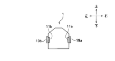
- FIG. 22 when the plug 1 and the jack 2 have a plurality of optical transmission paths (two systems in FIG. 22), wipers (19a (19a (19a, 19b, 19b)) corresponding to the respective lenses (11a, 11b, 21a, 21b). ), 19b (19), 29a (29), 29b (29)).
- the configuration shown in FIG. 22 is equivalent to the configuration shown in FIG. 13 having four wipers.
- Each of the wipers 19a, 19b, 29a, and 29b contacts the surfaces of the lenses 21a, 21b, 11a, and 11b when the plug 1 is inserted and removed, and sweeps the surfaces of these lenses while the plug 1 is inserted and removed. With such a configuration, there is an effect that foreign matters are reliably removed from all lenses.
- the configuration of the plug 1 shown in FIG. 23 is equal to the configuration of the plug 1 shown in FIG.
- the configuration of the jack 2 shown in FIG. 24 is equal to the configuration of the jack 2 shown in FIG. 23 and 24, it can be seen that the vertical widths of the wipers 19a, 19b, 29a, and 29b are larger than the vertical widths of the lenses 11a, 11b, 21a, and 21b. Accordingly, the wipers 19a, 19b, 29a, and 29b have an effect of sweeping the entire surfaces of the corresponding lenses 21a, 21b, 11a, and 11b.
- the wipers 19a, 19b, 29a, and 29b have the same dimensions, and the lenses 21a, 21b, 11a, and 11b have the same dimensions. The lens and wiper dimensions may be different.
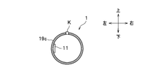
- the wiper can also be used for the cylindrical plug 1 and the jack 2 (see FIG. 1) fitted to the plug 1.
- the wiper 19c included in the cylindrical plug 1 is disposed in front of the lens 11 so that the lens 21 can be swept, and is a predetermined distance radially outward over the entire circumferential direction. It extends.
- the wiper 29c provided in the jack 2 fitted to the columnar plug 1 is disposed behind the lens 21 so as to sweep the lens 11, and extends over the entire circumferential direction. A predetermined distance extends radially outward. With such a configuration, there is an effect that foreign matters are reliably removed not only from the lenses 11 and 21 but also from the entire plug 1.
- the plug 1 has a cylindrical shape
- the plug accommodating portion C of the jack 2 corresponds to the shape of the plug 1.
- the plug 1 includes a shutter 31 (plug-side shutter) and a spring 32 (plug-side urging portion).
- the shutter 31 has a cylindrical shape, the plug 1 is inserted therethrough, and slides on the side surface of the plug 1.
- the shutter 31 includes a flange portion 31a that extends radially outward over the entire circumferential direction at the rear end portion.
- the length of the shutter 31 in the axial direction is a length that allows the inner surface of the shutter 31 to cover the lens 11 when the plug 1 is not inserted (see FIG. 27A).
- the inner diameter of the shutter 31 is substantially equal to the diameter of the leading portion of the plug 1 from the viewpoint of preventing entry of foreign matter such as dust. Further, the outer diameter of the shutter 31 is larger than the opening diameter of the jack 2 (shown by a one-dot chain line in FIG. 27C), that is, the diameter of the inlet portion of the plug housing portion C.
- the spring 32 is a means for urging the shutter 31 moved rearward with respect to the plug 1, and the plug 1 is inserted therethrough and is disposed inside the substantially cylindrical support portion S.
- the front end portion of the spring 32 is always in contact with the flange portion 31 a of the shutter 31.
- the rear end portion of the spring 32 is always in contact with a stepped portion of the plug 1 that extends radially outward inside the support portion S. Therefore, the spring 32 always urges the shutter 31 forward.
- the shutter 31 When the plug 1 is not inserted, the shutter 31 receives a force forward due to the biasing action of the spring 32. However, the flange portion 31 a of the shutter 31 is locked to the flange portion extending radially inward at the front end portion of the support portion S. Therefore, the shutter 31 is fixed at a predetermined position, and the shutter 31 does not come out of the plug 1.
- the shutter 31 when the plug 1 is not inserted, the shutter 31 covers the lens 11 (shutter closed state). Therefore, the shutter 31 reliably protects the lens 11 such that foreign matter can be prevented from entering the vicinity of the lens 11 when the plug 1 is not inserted, and the user can avoid touching the lens 11 with his / her hand. it can.
- the front end portion of the shutter 31 contacts the peripheral portion of the inlet portion of the plug housing portion C in the rear surface portion of the jack 2.
- the shutter 31 contracts the spring 32 and slides backward with respect to the plug 1 (withdrawing plug 1).
- the shutter 31 moves away from the position of the lens 11 (shutter open state), and the lens 11 is exposed from the shutter 31.
- the shutter 31 slides most rearward within the range in which it can move with respect to the plug 1 and is accommodated inside the support portion S.
- the lens 11 faces the lens 21.
- the spring 32 extends, so that the shutter 31 slides forward with respect to the plug 1 and covers the lens 11.
- the optical connector 100 of the present embodiment has a configuration in which the lens 11 is disposed on the side surface of the plug 1 and the lens 21 is disposed on the inner side surface of the jack 2. For this reason, the insertion / extraction direction of the plug 1 and the sliding direction of the shutter 31 can be made the same. Therefore, it is possible to realize an unprecedented feature that the shutter 31 is slid in the insertion / extraction direction of the plug 1 in conjunction with the user's normal operation of inserting / removing the plug 1 to open / close the shutter 31 with respect to the lens 11.
- the user simply performs a normal operation of inserting / removing the plug 1 to close the shutter 31 to protect the lens 11 when not inserted, and to open the shutter 31 to optically couple the lenses 11 and 21 when fitted.
- optical connectors are optically coupled between the tip of the plug and the back of the plug housing of the jack. Therefore, if a shutter is attached, a shutter that slides in a direction orthogonal to the plug insertion / extraction direction must be configured. As a result, the mechanism for opening and closing the shutter must be complicated, resulting in an increase in cost and a decrease in reliability.
- the optical connector 100 of this embodiment employs a configuration in which optical coupling is performed between the side surface of the plug 1 and the inner side surface of the jack 2. For this reason, the opening / closing operation
- the shutter 31 includes a wiper 33 (plug-side shutter wiper) that contacts and sweeps the surface of the lens 11 while the plug 1 is inserted and removed.
- the wiper 33 has an annular shape whose center coincides with the cylindrical shutter 31, and may be, for example, a nonwoven fabric.
- the wiper 33 is attached to the front end portion of the shutter 31 using, for example, an adhesive.
- the inner diameter of the wiper 33 is slightly smaller than the inner diameter of the shutter 31.
- the shutter 31 slides backward with respect to the plug 1. At that time, since the wiper 33 is rolled along the side surface of the plug 1, the lens 11 exposed from the shutter 31 can be swept without hindering insertion of the plug 1.
- the plug 1 is removed from the jack 2, the shutter 31 slides forward with respect to the plug 1 by the spring 32. At that time, since the wiper 33 is rolled along the side surface of the plug 1, the lens 11 to be covered by the shutter 31 can be swept without hindering the extraction of the plug 1.
- the wiper 33 sweeps the surface of the lens 11 by the opening / closing operation of the shutter 31 in conjunction with the user's normal operation of inserting / removing the plug 1, foreign matter can be reliably removed from the lens 11.
- the wiper 33 shown in FIG. 28 is attached to the front end portion of the shutter 31 over the entire circumferential direction, not only the lens 11 but also the entire side surface of the leading portion of the plug 1 can be removed by inserting and removing the plug 1. Sweep.
- an angle fixing mechanism that fixes the position of the plug 1 in the insertion / extraction direction with respect to the jack 2, for example, a key mechanism including a key provided on the plug 1 and a key groove provided on the jack 2, Foreign matter can be reliably removed from the lens 11.
- the shape of the wiper 33 may be changed so as to sweep only a partial region of the side surface of the plug 1 including the surface of the lens 11.
- the shape of the plug 1 is not limited to a cylindrical shape, and may be an elliptical column shape, a square column shape, a trapezoidal column shape, or another column shape.
- the shape of the plug accommodating portion C of the jack 2 may correspond to the shape of the plug 1.
- the jack 2 includes a shutter 41 (jack-side shutter) and a spring 42 (jack-side biasing portion).
- the shutter 41 has a substantially cylindrical shape and slides on the inner surface of the jack 2.
- the shutter 41 includes a protruding portion 41a that extends upward and downward partially over the axial direction at the upper end portion and the lower end portion of the side surface.
- the convex portion 41a is preferably formed at a position that does not face the lens 21 (in FIGS. 29A to 29C, it is shifted by 90 degrees in the circumferential direction).
- the length of the shutter 41 in the axial direction is a length that allows the side surface of the shutter 41 to cover the lens 21 when the plug 1 is not inserted (see FIG. 29A).
- the axial length of the shutter 41 is preferably the minimum necessary length that covers the lens 21.
- the diameter of the shutter 41 is substantially equal to the hole diameter of the plug housing portion C of the jack 2 from the viewpoint of preventing entry of foreign matter such as dust.
- a concave recessed portion 2a that engages with the convex portion 41a of the shutter 41 in the circumferential direction is formed on the inner side surface of the jack 2. Since the recessed portion 2a is formed by a predetermined length with respect to the axial direction, the protruding portion 41a can move in the axial direction while entering the inside of the recessed portion 2a. , And can slide in the axial direction with respect to the inner surface of the jack 2.
- the spring 42 is a means for urging the shutter 41 moved forward with respect to the jack 2 in the backward direction, and is disposed in the plug accommodating portion C of the jack 2.
- the front end portion of the spring 42 is always in contact with the deepest portion of the plug housing portion C of the jack 2.
- the rear end portion of the spring 42 is in contact with the front end portion of the shutter 41. Therefore, the spring 42 always urges the shutter 41 backward.
- the shutter 41 When the plug 1 is not inserted, the shutter 41 receives a force backward due to the biasing action of the spring 42. However, the protruding portion 41 a of the shutter 41 is locked to the rear end portion of the recessed portion 2 a of the jack 2. Therefore, the shutter 41 is fixed at a predetermined position, and the shutter 41 does not come out of the jack 2. As shown in FIG. 29E, the concave portion 2a (the convex portion 41a of the shutter 41) is disposed at a position shifted by 90 degrees in the axial direction from the lens 21.
- the shutter 41 covers the lens 21 (shutter closed state). Therefore, the shutter 41 can reliably protect the lens 21 such as suppressing the entry of foreign matter into the vicinity of the lens 21 when the plug 1 is not inserted.
- the tip of the plug 1 comes into contact with the rear end of the shutter 41.
- the shutter 41 contracts the spring 42 and slides in the forward direction (the jack back direction). As a result, the shutter 41 moves away from the position of the lens 21 (shutter open state), and the lens 21 is exposed from the shutter 41.
- the shutter 41 slides slightly rearward of the deepest portion of the plug housing portion C with respect to the jack 2, and the lens 21 moves to the lens 11. opposite.
- the spring 42 extends, so that the shutter 41 slides backward with respect to the jack 2 and covers the lens 21.
- the optical connector 100 of this embodiment can make the insertion / extraction direction of the plug 1 and the sliding direction of the shutter 31 the same, it is interlocked with the user's normal operation of inserting / removing the plug 1. It is possible to realize an unprecedented feature that the shutter 41 is slid in the insertion / extraction direction of the plug 1 and the shutter 41 is opened / closed with respect to the lens 21. The user performs the normal operation of inserting and removing the plug 1 to close the shutter 41 to protect the lens 21 when not inserted, and to open the shutter 41 and optically couple the lenses 11 and 21 when fitted. Are compatible. As a result, it is possible to greatly reduce the possibility that foreign matter will affect the light transmission performed by the optical connector.
- the optical connector 100 has an extremely simple structure with a small number of required parts as described above, and is linked to the user's normal operation of inserting and removing the plug 1.
- the opening / closing operation of the shutter 41 can be realized.
- the shutter 41 includes a wiper 43 (jack-side shutter wiper) that contacts and sweeps the surface of the lens 21 while the plug 1 is inserted and removed.
- the wiper 43 has a fan shape, and the vertex of the wiper 43 coincides with the center of the cylindrical shutter 41.
- the wiper 43 may be a non-woven fabric, for example.
- the wiper 43 is attached to the rear end portion of the shutter 31 using, for example, an adhesive.
- the radius of the wiper 43 is slightly larger than the radius of the shutter 41.
- the shutter 41 slides forward. At that time, the wiper 43 can sweep along the inner surface of the jack 2 and sweep the lens 21 exposed from the shutter 41 without hindering the insertion of the plug 1. Further, when the plug 1 is pulled out from the jack 2, the shutter 41 slides backward by the spring 42. At that time, since the wiper 43 is rolled along the inner surface of the jack 2, the lens 21 to be covered by the shutter 41 can be swept without hindering the extraction of the plug 1.
- the wiper 43 sweeps the surface of the lens 21 by the opening / closing operation of the shutter 41 in conjunction with the user's normal operation of inserting / removing the plug 1, foreign matter can be reliably removed from the lens 21.
- the shape of the plug 1 is not limited to a cylindrical shape, and may be an elliptical column shape, a square column shape, a trapezoidal column shape, or another column shape.
- the shape of the plug accommodating portion C of the jack 2 may correspond to the shape of the plug 1.
- an optical connector composed of the plug 1 having the shutter 31 and the jack 2 having the shutter 41 can be realized, and both the lenses 11 and 21 can be protected.
- the optical coupling unit included in the plug 1 is the ball lens 112
- the optical coupling unit included in the jack 2 is the ball lens 212.
- the jack 2 forms an airflow groove 51 (jack-side airflow groove) extending in the axial direction through the exposed surface of the ball lens 212 on the inner surface of the jack 2. is doing.
- the airflow groove 51 extends from the inlet portion of the plug housing portion C to the deepest portion. However, if the foreign matter removal by the airflow described later functions, the airflow groove 51 does not need to extend to the deepest portion.
- the plug 1 shown in FIGS. 31A and 31B has a cylindrical shape, and the shape of the plug accommodating portion C of the jack 2 corresponds to the shape of the plug 1.
- the depth of the airflow groove 51 that is, the length in the left-right direction
- the ball lens 212 is preferably arranged so that the substantially right half of the ball lens 212 is exposed in the airflow groove 51.
- the width of the airflow groove 51 that is, the length in the vertical direction, is designed in the range of 80% to 100% of the diameter of the ball lens 212 in consideration of the effective beam path of the ball lens 212.
- the space in the airflow groove 51 designed as described above is sufficiently large with respect to the original gap between the side surface of the plug 1 and the inner surface of the jack 2. Therefore, the airflow generated in the plug housing portion C is concentrated on the front side of the airflow groove 51 with respect to the ball lens 212.
- the concentrated air flow proceeds backward in the air flow groove 51 with a predetermined pressure, passes through the surface of the ball lens 212, and is discharged to the outside from the inlet portion of the plug housing portion C (See the arrow shown in FIG. 31 (a)).
- the airflow generated due to the insertion of the plug 1 can be removed by blowing off the foreign matter adhering to the ball lens 212.
- the cleaning of the optical coupling portion provided on the inner surface of the jack 2 that is difficult for general users to clean is an operation necessary for the fitting of the plug 1 and the jack 2, that is, the insertion of the plug 1, just before the fitting. It can be executed at the most effective timing each time.
- the optical coupling portion can be cleaned only by providing a very simple airflow passage groove as described above, which is a feature unique to the present invention in which the optical coupling portion is provided on the side surface of the plug 1 and the inner side surface of the jack 2. is there.
- the conventional optical connector having the optical coupling portion at the tip of the plug the airflow direction cannot be effectively controlled with the airflow passage groove thus simplified, so the surface of the optical coupling portion is cleaned by the airflow. I can't.
- the ball lens 212 when the ball lens 212 is arranged so that the exposed portion of the ball lens 212 present in the airflow groove 51 is arranged on the inner side of the jack 2 (the side occupied by the jack 2; the left side in FIG. 31). Good.
- the airflow groove 51 is such that the right apex portion of the ball lens 212 is positioned radially outside the cylindrical plug 1 inserted into the jack 2 by a predetermined distance from the inner surface of the jack 2.
- An exposed portion of the ball lens 212 existing inside may be disposed (retraction of the ball lens 212 from the plug 1).
- an airflow path can be secured with an appropriate size between the right apex portion of the ball lens 212 and the side surface of the plug 1, so that the airflow generated due to the insertion of the plug 1 is The foreign matter adhering to the ball lens 212 can be blown away more efficiently.
- the passage of the air current is narrowed according to the shape of the ball lens 212. For this reason, the flow velocity of the airflow when passing through the ball lens 212 is larger than the flow velocity of the airflow before and after passing through the ball lens 212. Therefore, the airflow passing between the ball lens 212 and the side surface of the plug 1 can be removed by blowing off the foreign matter adhering to the ball lens 212 more vigorously.
- the shape of the plug 1 is not limited to a cylindrical shape, and may be an elliptical column shape, a quadrangular column shape, a trapezoidal column shape, or another column shape.
- the shape of the plug accommodating portion C of the jack 2 may correspond to the shape of the plug 1.
- the shape of the airflow groove 51 is not limited to a linear shape along the front-rear direction, and may be another shape such as a spiral shape, for example.
- the optical coupling portion that can be adopted in the present embodiment is not limited to a ball lens, and for example, a lens having a flat surface can also be applied.
- the plug 1 forms, on the side surface of the plug 1, an airflow groove 52 (plug-side airflow groove) that extends in the axial direction through the exposed surface of the ball lens 112. ing.
- the airflow groove 52 extends from the distal end portion of the plug 1 to the support portion S.
- the plug 1 shown in FIGS. 32A and 32B has a columnar shape, and the shape of the plug housing portion C of the jack 2 corresponds to the shape of the plug 1.
- the depth of the airflow groove 52 that is, the length in the left-right direction
- the ball lens 112 is preferably arranged so that the substantially left half of the ball lens 112 is exposed in the airflow groove 52.
- the width of the airflow groove 52 that is, the length in the vertical direction is designed in a range of 80% to 100% of the diameter of the ball lens 112 in consideration of the effective beam path of the ball lens 112.
- the space in the airflow groove 52 designed as described above is sufficiently large with respect to the original gap between the side surface of the plug 1 and the inner side surface of the jack 2. Therefore, the air flow generated in the plug housing portion C is concentrated on the front portion of the air flow groove 52 with respect to the ball lens 112. The concentrated air flow proceeds backward in the air flow groove 52 with a predetermined pressure, passes through the surface of the ball lens 112, and is discharged to the outside from the inlet portion of the plug housing portion C ( (See the arrow shown in FIG. 32 (a)).
- the air flow generated due to the insertion of the plug 1 can be removed by blowing away the foreign matter adhering to the ball lens 112. As a result, it is possible to greatly reduce the possibility that foreign matter will affect the light transmission performed by the optical connector. Since the air flow is generated only by the user's normal operation of inserting the plug 1, no special operation is required from the user.
- the removal of foreign matter in the airflow groove 52 of the plug 1 inserted into the jack 2 can be realized at the timing just before the mating when the foreign matter removal is most useful.
- the optical coupling portion can be cleaned only by providing a very simple airflow passage groove as described above, which is a feature unique to the present invention in which the optical coupling portion is provided on the side surface of the plug 1 and the inner side surface of the jack 2. is there.
- the conventional optical connector having the optical coupling portion at the tip of the plug the airflow cannot be effectively controlled with the airflow passage groove simplified as described above, so that the surface of the optical coupling portion can be cleaned by the airflow. Can not.
- the ball lens 112 may be arranged so that the exposed portion of the ball lens 112 existing in the airflow groove 52 is arranged inside the side surface of the plug 1.
- the ball lens 112 existing in the airflow groove 52 so that the left apex portion of the ball lens 112 is located on the radial inner side of the cylindrical plug 1 by a predetermined distance from the side surface of the plug 1. It is preferable to arrange an exposed portion of the ball lens 112 (retraction of the ball lens 112 from the jack 2).
- an airflow path can be secured in an appropriate size between the left apex portion of the ball lens 112 and the inner surface of the jack 2, so that the airflow generated due to the insertion of the plug 1 Can more efficiently blow off and remove foreign matter adhering to the ball lens 112.
- the path of the airflow is narrowed according to the shape of the ball lens 112. For this reason, the flow velocity of the airflow when passing through the ball lens 112 increases as compared with the flow velocity of the airflow before and after passing through the ball lens 112. Therefore, the airflow passing between the ball lens 112 and the inner surface of the jack 2 can be removed by blowing off the foreign matter adhering to the ball lens 112 more vigorously.
- the shape of the plug 1 is not limited to a cylindrical shape, and may be an elliptical column shape, a quadrangular column shape, a trapezoidal column shape, or another column shape.
- the shape of the plug accommodating portion C of the jack 2 may correspond to the shape of the plug 1.
- the shape of the airflow groove 52 is not limited to a linear shape along the front-rear direction, and may be another shape such as a spiral shape, for example.
- a part of the cylindrical plug 1 is cut out along the front-rear direction to expose a part of the ball lens 112, thereby securing a passage for the air flow including the air flow groove 52a. May be.
- the optical coupling portion that can be employed in the present embodiment is not limited to a ball lens, and can be applied to, for example, a lens having a flat surface.
- the plug 1 having the airflow groove 52 is a modification of the plug 1 shown in FIG. 32, and has a trapezoidal column shape instead of a columnar shape (see FIG. 33B).
- the shape of the plug accommodating portion C of the jack 2 is a shape corresponding to the trapezoidal columnar shape exhibited by the plug 1 of FIG. Therefore, the optical connector 100 including the plug 1 and the jack 2 in FIG. 33 can realize an angle fixing mechanism that fixes the position around the axis in the insertion / extraction direction of the plug 1 with respect to the jack 2.
- the position around the axis in the insertion / extraction direction of the plug 1 with respect to the jack 2 is determined from the start of insertion of the plug 1 to the time of fitting. That is, the insertion angle in the circumferential direction of the plug 1 can be kept constant by the angle fixing mechanism.
- the ball lens 112 may be arranged so that the exposed portion of the ball lens 112 existing in the airflow groove 52 is arranged inside the side surface of the plug 1 in the same manner as in the embodiment shown in FIG.
- the ball lens 112 existing in the airflow groove 52 is positioned so that the left apex portion of the ball lens 112 is located on the inner side of the trapezoidal columnar plug 1 by a predetermined distance from the side surface of the plug 1. It is good to arrange an exposed part.
- the ball lens 212 of the jack 2 is opened to the space in the airflow groove 52 after the plug 1 is inserted by the angle fixing mechanism of the optical connector 100. Therefore, the airflow generated due to the insertion of the plug 1 passes through not only the surface of the ball lens 112 but also the surface of the ball lens 212 and is discharged to the outside from the inlet portion of the plug housing portion C (FIG. 33). (See arrow shown in (a)). Therefore, the airflow generated due to the insertion of the plug 1 can be removed by blowing away not only the foreign matter attached to the ball lens 112 but also the foreign matter attached to the ball lens 212. As a result, it is possible to greatly reduce the possibility that foreign matter will affect the light transmission performed by the optical connector.
- the plug 1 has only one groove, the airflow groove 52, and the optical coupling portion provided on the inner surface of the jack 2, which is difficult for general users to clean, and the side surface of the plug 1. Cleaning of the optical coupling portion provided can be performed just before the mating by an operation itself necessary for mating the plug 1 and the jack 2 such as insertion of the plug 1.
- the plug 1 is provided with a key 53 that extends radially outward on the right side in the circumferential direction, and corresponds to the key 53.
- a key mechanism provided with the groove 54 in the jack 2 may be adopted.
- the key 53 is formed on the side surface of the plug 1 until it reaches the support portion S from the tip end portion of the plug 1.
- the keyway 54 can receive the entire key 53 when fitted.
- the angle fixing mechanism may be provided in the plug 1 and the jack 2 in the embodiment shown in FIG.
- the airflow generated due to the insertion of the plug 1 can be removed by blowing away not only the foreign matter attached to the ball lens 212 but also the foreign matter attached to the ball lens 112. Therefore, the cleaning of the optical coupling portion provided on the inner side surface of the jack 2 and the cleaning of the optical coupling portion provided on the side surface of the plug 1 can be realized together.
- the plug 1 has the airflow groove 51 described in the embodiment of FIG. 31, and the jack 2 has the airflow groove 52 described in the embodiment shown in FIG. ing.
- the plug 1 includes a key 53 that is formed from the tip of the plug 1 until it reaches the support S, and the jack 2 corresponds to the key 53.
- the key groove 54 By providing the key groove 54, an angle fixing mechanism of the optical connector 100 is realized.
- the space portion designed as described above is sufficiently large with respect to the original gap between the side surface of the plug 1 and the inner surface of the jack 2. Therefore, the airflow generated in the plug housing portion C is concentrated on the front side of the airflow groove 51 with respect to the ball lens 212. The concentrated airflow proceeds backward in the space with a predetermined pressure, passes through the surfaces of the ball lenses 112 and 212, and is discharged to the outside from the inlet portion of the plug housing portion C ( (See the arrow shown in FIG. 34 (a)).
- the airflow generated due to the insertion of the plug 1 can be removed by blowing away not only the foreign matter attached to the ball lens 112 but also the foreign matter attached to the ball lens 212. As a result, it is possible to greatly reduce the possibility that foreign matter will affect the light transmission performed by the optical connector.
- the exposed portion of the ball lens 112 existing in the airflow groove 52 and the exposure of the ball lens 212 existing in the airflow groove 51 can be disposed inside the plug 1 and the ball lens 212 can be disposed inside the jack 2 so that the portion approaches the minute distance when fitted.
- the ball lens 112 can be arranged inside the plug 1 so that the left apex portion of the ball lens 112 is located slightly inside the outer diameter of the plug 1.
- the ball lens 212 can be arranged inside the jack 2 so that the right apex portion of the ball lens 212 is located slightly inside (the side occupied by the jack 2) from the inner side surface of the jack 2.
- the jack 2 is partially opposed to the airflow groove 52 during insertion of the plug 1.
- the airflow grooves 51 provided in the airflow function as airflow paths (see FIG. 34A). For this reason, the airflow generated due to the insertion of the plug 1 can be removed by blowing off the foreign matter adhering to the ball lens 112.
- the airflow groove 51 is partially opposed during insertion of the plug 1.
- the airflow groove 52 provided in the plug 1 functions as an airflow path (see FIG. 34A). For this reason, the airflow generated due to the insertion of the plug 1 can be removed by blowing off the foreign matter adhering to the ball lens 212.
- airflow grooves 51 and 52 are provided in both the plug 1 and the jack 2 as compared with the case where the airflow grooves are provided in either the plug 1 or the jack 2.
- FIG. 1 the ball lenses 112 and 212 can be brought close to each other at the time of fitting.
- the efficiency of optical coupling improves as the distance between two optical coupling portions during fitting decreases. Therefore, according to the embodiment shown in FIG. 34, the efficiency of optical coupling between the ball lenses 112 and 212 can be further improved.
- the cleaning action for removing the foreign matter adhering to the ball lenses 112 and 212 functions until just before the ball lenses 112 and 212 face each other, that is, until just before the plug 1 and the jack 2 are fitted together. For this reason, the foreign matter adhering to the ball lenses 112 and 212 can be removed until the timing immediately before the fitting when the foreign matter removal is most useful.
- the airflow groove 51 of the jack 2 does not sufficiently function as an airflow path, the airflow groove 52 of the plug 1 can function as an airflow path, and the cleaning operation for removing foreign matter is maintained. Therefore, as shown in FIG. 34, the airflow groove 51 does not need to extend to the deepest portion of the plug housing portion C. Further, as compared with the embodiment shown in FIGS. 31 to 33, the distance of the airflow groove 51 extending forward from the inlet portion of the plug housing portion C can be further shortened. More specifically, the airflow groove 51 only needs to extend slightly ahead of the ball lens 212.
- the optical fiber 12 in the plug 1 is preferably arranged in a straight line in consideration of optical transmission characteristics, but if the light can be transmitted to the optical coupling portion such as the lens 11, the optical fiber 12 can be arbitrarily arranged. It can be bent into a shape and placed in the plug 1.
- two optical fibers in two integrated plugs can be arranged so as to cross and extend toward the optical coupling portion on the side surface of the corresponding plug. With such an arrangement, it is not necessary to bend the optical fiber so much, so that it is possible to suppress deterioration of the optical transmission characteristics. The same applies to the optical fiber 22 in the jack 2.
- the optical coupling portion such as the lens 11
- the light traveling toward the lens 11 is incident on the side surface of the lens 11 not only vertically but also obliquely.
- the optical fiber 12 or the optical path changing unit 18 can be arranged so that light is incident on the side surface of the lens 11 from an oblique direction. Even with such a configuration, optical coupling between the lens 11 and the lens 21 of the jack 2 can be realized. By setting it as such a structure, the influence of the reflected light in an optical coupling part can be reduced. The same applies to the optical coupling portion such as the lens 21 of the jack 2.
- the spring 32 included in the plug 1 can be replaced with a magnet (plug side urging portion).
- the shutter 31 of the plug 1 can be slid in the front-rear direction not by the biasing action of the spring 32 but by the biasing action of the magnet.
- the spring 42 provided in the jack 2 can be replaced with a magnet (jack side biasing portion).
- the shutter 41 of the plug 1 can be slid in the front-rear direction by the biasing action of the magnet, not the biasing action of the spring 42.
- the spring 42 and the magnet may be used in combination.
Landscapes
- Physics & Mathematics (AREA)
- General Physics & Mathematics (AREA)
- Optics & Photonics (AREA)
- Optical Couplings Of Light Guides (AREA)
- Mechanical Coupling Of Light Guides (AREA)
Description
本発明は、プラグジャック式の光コネクタの技術に関する。
近年、光ケーブルおよび光コネクタの技術開発が盛んに行われている。例えば、特許文献1は、光ジャック(ジャック)にプラグを挿入し、嵌合すると、プラグの先端部と、プラグを収容する光ジャックのボディ(プラグ収容部)の奥部に組み込まれた光素子とが対向する光コネクタについて開示している。つまり、特許文献1の光コネクタが行う光の伝送は、光ジャックのプラグ収容部の奥部と、そこにまで挿入されたプラグの先端部との間で行われる。
光コネクタを使用すると、ごみ、埃、または塵などの異物が、ジャックのプラグ収容部に混入し、光コネクタが行う光の伝送に影響を及ぼす場合がある。ここで、特許文献1の構成では、プラグ収容部の奥部に位置する光素子の付近に異物が入り込んでしまい、プラグを挿入することでその異物を押し込んでしまう可能性がある。その結果、光の伝送の障害(光信号の遮断など)、光素子の損傷などの事態を引き起こすおそれがある。
前記した影響を回避するために、光コネクタの当業者たちは、慣用的に、プラグの挿抜のたびにプラグおよびジャックをクリーニングする。また、光コネクタの未使用時にはプラグおよびジャックに保護キャップを被せたりもする。しかし、光コネクタに関する基本的知識を持たない一般のユーザにとっては、これらの措置をとることは煩雑すぎるため、前記ユーザが屋内外で使用する携帯端末などに光コネクタを導入することは容易でない。
このような事情に鑑みて、本発明は、光コネクタが行う光の伝送に異物が影響を及ぼす可能性を大幅に低減することを目的とする。
上記目的を達成するため、本発明の光コネクタは、光コネクタ用のプラグおよびジャックを備える。
前記プラグが保持するプラグ側光導波手段内を伝送する光を前記ジャックに対して光結合させるプラグ側光結合部が、前記プラグの側面に配置されている。
前記ジャックが保持するジャック側光導波手段内を伝送する光を前記プラグに対して光結合させるジャック側光結合部が、前記ジャックの内側面に配置されている。
詳細は、後記する。
前記プラグが保持するプラグ側光導波手段内を伝送する光を前記ジャックに対して光結合させるプラグ側光結合部が、前記プラグの側面に配置されている。
前記ジャックが保持するジャック側光導波手段内を伝送する光を前記プラグに対して光結合させるジャック側光結合部が、前記ジャックの内側面に配置されている。
詳細は、後記する。
本発明によれば、光コネクタが行う光の伝送に異物が影響を及ぼす可能性を大幅に低減することができる。
以下、本発明の実施形態を、図面を参照して詳細に説明する。なお、説明の便宜上、プラグをジャックに挿入する方向を「前」または「奥」と呼び、プラグをジャックから抜く方向を「後」と呼ぶ場合があり、上下左右方向は各図に従う。また、「垂直」という語は、「略垂直」の意味を含み、「平行」という語は、「略平行」の意味を含む。
(全体構成)
図1を参照すると、本実施形態の光コネクタ100(以下、単に、「光コネクタ」と呼ぶ。)は、略円柱状の外形を有する樹脂製のプラグ1と、略直方体の外形を有するジャック2とを備える。プラグ1は、ジャック2の内部に挿入される先頭部と、支持部Sと、ケーブル保護部Uとを備える。プラグ1の先頭部の側面には、2つのレンズ(光結合部)11a(11)、11b(11)が備えられているとともに、抜け止め用溝Rが形成されている。レンズ11については後記する。また、支持部Sに対してキーKが形成されている。一方、ジャック2には、嵌合するプラグ1を収容する穴となるプラグ収容部Cが形成されている。図1には、プラグ収容部Cの入口が図示されている。なお、ジャック2の左外側面には、光ファイバケーブルOCが接続されている。
図1を参照すると、本実施形態の光コネクタ100(以下、単に、「光コネクタ」と呼ぶ。)は、略円柱状の外形を有する樹脂製のプラグ1と、略直方体の外形を有するジャック2とを備える。プラグ1は、ジャック2の内部に挿入される先頭部と、支持部Sと、ケーブル保護部Uとを備える。プラグ1の先頭部の側面には、2つのレンズ(光結合部)11a(11)、11b(11)が備えられているとともに、抜け止め用溝Rが形成されている。レンズ11については後記する。また、支持部Sに対してキーKが形成されている。一方、ジャック2には、嵌合するプラグ1を収容する穴となるプラグ収容部Cが形成されている。図1には、プラグ収容部Cの入口が図示されている。なお、ジャック2の左外側面には、光ファイバケーブルOCが接続されている。
抜け止め用溝Rは、プラグ1の先端部近傍にて、周方向全体に沿って形成された溝(係合溝)である。抜け止め用溝Rに、ジャック2のプラグ収容部Cの奥部近傍に備えられる抜け止め係合部(図示せず)が嵌合時に係合すると、プラグ1の意図しない抜けを防止できる。なお、前記した抜け止め係合部は、例えば、プラグ収容部Cの周方向のほぼ全体に亘る板バネとして構成できる。
支持部Sは、ユーザが把持する部材であり、プラグ1の本体(支持部S以外のプラグ1の構成要素)およびプラグ1から後方へ延びるケーブルを保持する。
ケーブル保護部Uは、ケーブルに固定されており、支持部Sが、後方に移動することを規制する。
ケーブル保護部Uは、ケーブルに固定されており、支持部Sが、後方に移動することを規制する。
キーKは、支持部Sの前端面に形成され、ジャック2のキー溝Hに係合する形状を有する。プラグ1がジャック2に嵌合し(図2参照)、キー溝HにキーKが係合すると、ジャック2に対するプラグ1の挿抜方向(前後方向)の軸周りの位置が決まる。
(光結合部および光ファイバ)
図3を参照して、プラグ1が備えるレンズ11(プラグ側光結合部)、光ファイバ12(プラグ側光導波手段)およびジャック2が備えるレンズ21(ジャック側光結合部)、光ファイバ22(ジャック側光導波手段)について説明する。なお、説明の便宜上、図3において、プラグ1が備えるレンズ11、プラグ1が保持する光ファイバ12は1つだけ図示されている。また、ジャック2が備えるレンズ21、ジャック2が保持する光ファイバ22は1つだけ図示されている。なお、光ファイバ12、22は、それぞれプラグ1内部、ジャック2内部に形成された穴を通過しており、接着剤などを使用してプラグ1およびジャック2に対して固定されている。
図3を参照して、プラグ1が備えるレンズ11(プラグ側光結合部)、光ファイバ12(プラグ側光導波手段)およびジャック2が備えるレンズ21(ジャック側光結合部)、光ファイバ22(ジャック側光導波手段)について説明する。なお、説明の便宜上、図3において、プラグ1が備えるレンズ11、プラグ1が保持する光ファイバ12は1つだけ図示されている。また、ジャック2が備えるレンズ21、ジャック2が保持する光ファイバ22は1つだけ図示されている。なお、光ファイバ12、22は、それぞれプラグ1内部、ジャック2内部に形成された穴を通過しており、接着剤などを使用してプラグ1およびジャック2に対して固定されている。
レンズ11、21は、光ファイバ12内を伝送する光および光ファイバ22内を伝送する光に対して互いに光結合を行う。本実施形態での「光結合」とは、嵌合したプラグの光結合部およびジャックの光結合部を介して光の伝送を行うことをいう。レンズ11は、光ファイバ12内を伝送する光をジャック2に効率的に光結合させ、レンズ21は、光ファイバ22内を伝送する光をプラグ1に効率的に光結合させる。光結合部にレンズを採用することで、光結合の機能を高めることができる。
レンズ11、21はそれぞれ、接着剤などを使用してプラグ1、ジャック2に対して固定されている。レンズ11、21は、伝送する光をコリメート光にできるものが好ましい。図3では、レンズ11の外表面と、プラグ1の側面は、面一である。また、レンズ21の外表面と、ジャック2の内側面(つまり、プラグ収容部Cの表面)は、面一である。
光ファイバ12の端部は、レンズ11に接触していてもよいし、または光の伝送が効果的に実現されるようにレンズ11と隙間を空けて配置してもよい。なお、図3では、略円柱状のプラグ1の内部で前後方向に沿って延びている光ファイバ12を左方向に曲げて、光ファイバ12の端部がレンズ11に接触している。
光ファイバ22の端部は、レンズ21に接触していてもよいし、または光の伝送が効果的に実現されるようにレンズ21と隙間を空けて配置してもよい。なお、図3では、ジャック2の内部で光ファイバ22は左右方向に直線状に配置されているが、図13に示すように曲げた形態でも構わない。
レンズ11は、プラグ1の側面(図3では左側面)に配置されている。また、レンズ21は、ジャック2の内側面に配置されており、嵌合時ではキーKとキー溝Hとにより、レンズ11に対して軸周りの位置を一致させることができる。このように側面に配置される構成が、従来例には無い本発明の最大の特徴である。なお、レンズ11とレンズ21との軸方向(前後方向)の位置決めは、プラグ1の先端部をジャック2のプラグ収容部Cの奥部に突き当てることで行われる。
従来例では、プラグの先端部とジャックのプラグ収容部の奥部とで光結合を行う構成を採っていた。よって、ジャックのプラグ収容部に混入した異物の大部分は、プラグ収容部の奥部に蓄積されてしまい、光結合を阻害し、光の伝送に多大な影響を及ぼすことがあった。
本実施形態の構成によれば、レンズ21は、ジャック2の奥部から離れた位置でかつジャック2の内側面に配置されている。このため、異物が蓄積されやすいジャック2の奥部から離れた配置になるとともに、異物の侵入方向となるプラグ挿抜方向(前後方向)とレンズ21の表面が直交する。したがって、従来例と比較して非嵌合時にレンズ表面に異物が蓄積・付着しづらい構成となっている。一方、嵌合時において、レンズ11はジャック2の奥部から離れた位置にあるため、奥部に蓄積されている異物とは所定の距離だけ離れることになる。また、プラグ1をジャック2に挿入するときは、プラグ1の先頭部の先端が、プラグ収容部Cの任意の場所に混入していた異物を奥へ押しやるため、前記異物は、レンズ11、21とは所定の距離だけ離れる。その結果、異物がレンズ11、21に近づく可能性は低く、光コネクタが行う光の伝送に異物が影響を及ぼす可能性を大幅に低減することができる。また、プラグ1をジャック2から抜くときも同様である。したがって、従来例のようにプラグ1の挿抜時に、光コネクタのクリーニングや保護キャップの着脱が不要になり、光コネクタに関する基本的知識を持たないユーザでも容易に取り扱えるようになる。よって、屋内外を問わず塵や埃などの異物が多く存在する環境下で使用される携帯端末などの機器に光コネクタを容易に導入できる。
光結合部は、さまざまな形態をとることができる。例えば、図4に示すように、レンズ11の外表面がプラグ1の側面内側に位置して凹部を形成し、レンズ21の外表面がジャック2の内側面内側に位置して凹部を形成してもよい。光結合を十分に実現できるのであれば、レンズ11と、レンズ21との間に隙間を形成してもよい。
また、図5に示すように、レンズ11の外表面がプラグ1の側面外側に位置して凸部を形成し、レンズ21の外表面がジャック2の内側面外側(プラグ収容部Cが占める側。図5において右側)に位置して凸部を形成してもよい。このようなレンズ11、21が突出する構成によれば、嵌合時にレンズ11、21同士を擦ることができ、レンズ11、21に付着した異物を確実に除去できる。
また、図6に示すように、プラグ1の光結合部は、レンズ11を保護する保護部13(プラグ側保護部)を有し、ジャック2の光結合部は、レンズ21を保護する保護部23(ジャック側保護部)を有してもよい。保護部13、23によって、レンズ11、21の破損を確実に防止できる。保護部13、23はそれぞれ、接着剤などを使用してプラグ1、ジャック2に対して固定されている。保護部13、23は、光ファイバ12、22内を伝送する光を透過する材料でかつ好適にはレンズよりも硬い材料で作製できる。こうすることで、保護部13、23による光コネクタの光結合は阻害されない。
保護部13は、プラグ1の側面外側に位置して凸部を形成し、保護部23は、ジャック2の内側面外側に位置して凸部を形成してもよい。このような保護部13、23が突出する構成によれば、嵌合時に保護部13、23同士を擦ることができ、保護部13、23に付着した異物を確実に除去できる。
光結合部に光ファイバから出射した光の径を拡大する機能を持たせることは、おおいに有用である。図7には、プラグ1が備える光結合部としてのボールレンズ111が光ファイバ12の端部と隙間を空けて配置され、ジャック2が備える光結合部としてのボールレンズ211が光ファイバ22の端部と隙間を空けて配置されている構成が図示されている。
ボールレンズ111は、光ファイバ12のコア121からの出射光の伝播光径をほぼレンズの径にまで拡大するとともに、コリメート光にする。拡大されたコリメート光は、ボールレンズ211によって、光ファイバ22のコア221に集光される。
このような伝播光径の拡大により、光結合部同士の嵌合時の位置合わせ精度を緩和できる。また、ボールレンズに異物が付着しても光の伝送がその異物によって遮断される可能性を低減できる。なお、光ファイバとレンズ(ボールレンズ)との距離、レンズの焦点距離、形状などは、光ファイバのNA(Numerical Aperture)を考慮した上で、所望の伝播光径を実現できるように設計される。なお、コリメート光を生成するレンズとしては、ボールレンズの他に対物レンズなどを使用しても構わない。
一方、図8に示すように、レンズ11およびレンズ21を備えず、光ファイバ12の端部および光ファイバ22の端部だけで光結合部を構成することもできる。光ファイバ12の端部がプラグ1の側面内側に位置して凹部を形成し、光ファイバ22の端部がジャック2の内側面内側に位置して凹部を形成してもよい。このような構成すれば、光結合部の設計を単純化でき、かつ部品および実装点数の少なくともいずれかの削減を通じてコストの低減を図ることができる。なお、光ファイバ12の端部は、プラグ1の側面と面一であったり、プラグ1の側面から外側に突出したりしてもよく、プラグ1の側面近傍に位置してもよい。光ファイバ22の端部は、ジャック2の内側面と面一であったり、ジャック2の内側面から外側に突出したりしてもよく、ジャック2の内側面近傍に位置してもよい。
図9は、光結合部の具体的構成の一例を示す。プラグ1の光結合部は、ボールレンズ111(図7参照)と、台座部14と、2つのスプリング15とを備える。ジャック2の光結合部は、ボールレンズ211(図7参照)と、台座部24と、2つのスプリング25とを備える。なお、図9では、光ファイバ12を保持し、プラグ1に固定されているフェルール16と、光ファイバ22を保持し、ジャック2に固定されているフェルール26とが図示されている。
台座部14は、ボールレンズ111の回転が滑らかとなるように左方向(前後方向の垂直方向外側。プラグ1の径方向外側。)へボールレンズ111を支持する。台座部14の中心部には、左右方向(前後方向の垂直方向)に沿った孔14aが形成されており、光結合を阻害しない。
スプリング15は、フェルール16と台座部14との間に配置されており、左方向へ台座部14を弾性的に支持する。
プラグ1の側面には、光ファイバ12用に形成した穴の内壁部端部からその穴の径方向内側に延びるフランジとなるストッパ(係止部)L1が形成されている。ストッパL1は、左側(前後方向の垂直方向外側)からボールレンズ111を係止し、ボールレンズ111の飛び出しを防ぐ。プラグ1の未挿入時では、ボールレンズ111の一部がプラグ1の側面よりも外側に露出している。プラグ1の挿抜時には、スプリング15の付勢作用によりボールレンズ111の露出の程度が、プラグ1の側面とジャック2の内側面との間隔に応じて変化する。そして、ボールレンズ111の一部は、ジャック2の内側面上で擦れて回転する。ボールレンズ111の回転によって、ボールレンズ111に異物が付着していた場合においても、その異物はストッパL1の位置に移動し、結果的に除去される。
ボールレンズ111の回転により、ボールレンズ111に付着した異物のみならずプラグ収容部C内に存在した異物の除去も期待できる。これは、ボールレンズ111の回転に伴い、プラグ収容部C内に存在した異物がボールレンズ111に付着する場合に実現される。また、ボールレンズ111が擦れるときに生じ得るボールレンズ111表面上の傷が、ボールレンズ111の一箇所に集中せず分散する。その結果、光コネクタの光伝送特性の劣化を大幅に抑制できる。また、プラグ1の側面とジャック2の内側面との間隔が非常に小さい場合であっても、スプリング15は収縮するため、ボールレンズ111のジャック2との接触時の圧力は小さくなる。このため、プラグ1を勢いよく挿入するなどして大きな傷を与えかねないボールレンズ111の高圧力の擦れを回避できる。
ストッパL1の形状は、図9に示した形状に限定されず、例えばボールレンズ111の形状に対応する形状であってもよい。また、スプリング15は、1個または3個以上であってもよい。
なお、ジャック2の光結合部を構成する台座部24およびその孔24a、スプリング25は、プラグ1の光結合部の台座部14、孔14a、スプリング15と同様であり、ジャック2の光結合部は、プラグ1の光結合部と同様に機能する。また、ジャック2のストッパL2は、プラグ1のストッパL1と同様に機能する。このため、ジャック2に関する説明を省略する。
図9に例示したようにプラグ1とジャック2の両方に同一の構成を備える必要は必ずしもない。例えばジャック2のみに図9の光結合部を適用し、プラグ1には図4、図5、図6、図7に例示した光結合部の構成を採用しても構わない。その逆に、プラグ1のみに図9の光結合部を適用し、ジャック2には図4、図5、図6、図7に例示した光結合部の構成を採用しても構わない。このような構成とすることで、小型化、低コスト化の利点が生じる。
なお、ジャック2の光結合部を構成する台座部24およびその孔24a、スプリング25は、プラグ1の光結合部の台座部14、孔14a、スプリング15と同様であり、ジャック2の光結合部は、プラグ1の光結合部と同様に機能する。また、ジャック2のストッパL2は、プラグ1のストッパL1と同様に機能する。このため、ジャック2に関する説明を省略する。
図9に例示したようにプラグ1とジャック2の両方に同一の構成を備える必要は必ずしもない。例えばジャック2のみに図9の光結合部を適用し、プラグ1には図4、図5、図6、図7に例示した光結合部の構成を採用しても構わない。その逆に、プラグ1のみに図9の光結合部を適用し、ジャック2には図4、図5、図6、図7に例示した光結合部の構成を採用しても構わない。このような構成とすることで、小型化、低コスト化の利点が生じる。
図10は、図9に示す光結合部の他の構成例を示す。プラグ1の光結合部は、ボールレンズ111と、スプリング15aとを備える。ジャック2の光結合部は、ボールレンズ211と、スプリング25aとを備える。
図10のスプリング15aは、図9に示すスプリング15とは異なり、ボールレンズ111とは(台座部14の厚さよりも)大きな間隔を空けて、左方向へフェルール16を弾性的に支持する。具体的には、フェルール16と一体化したフランジとして機能するストッパL1bと、プラグ1の本体を成形してフランジとして機能するストッパ17との間にスプリング15aを配置して、フェルール16を弾性的に支持する。スプリング15aの径は、フェルール16の径よりも大きく、スプリング15aの内部にフェルール16の端部(破線表示)が挿入されている。
フェルール16の他の端部は、ボールレンズ111を左方向へ支持する。フェルール16の他の端部は、ボールレンズ111の回転を滑らかにする曲面を有するとともに、その中心部には穴が形成されている。その穴の奥部には、光ファイバ12の端部が存在する。
プラグ1の側面には、図9のストッパL1と同様に機能するストッパL1aが形成されている。ストッパL1aは、ボールレンズ111の回転を滑らかにする曲面を有する。
ボールレンズ111に対するスプリング15aの作用は、図9のスプリング15の作用と同様である。フェルール16がスプリング15aの内側にあるため、スプリング15aが収縮すると、フェルール16は、左右方向に安定的に移動することができる。ボールレンズ111に外部から圧力がかかった場合、ストッパL1bは、右方向(前後方向の垂直方向内側。プラグ1の径方向内側。)へ移動し、スプリング15aは縮む。その圧力から解放されると、スプリング15aの付勢作用により、ストッパL1b、フェルール16、およびボールレンズ111は、左方向へ移動し、ボールレンズ111の一部がプラグ1の側面よりも外側に露出する。
図10の構成によれば、スプリング15aの収縮状態とは無関係に、ボールレンズ111と光ファイバ12の端部との距離を所定の距離に維持することができる。その結果、ボールレンズ111からの出射光を常時コリメート光にすることができ、光伝送特性を安定化できる。
ストッパL1aの形状は、図10に示した形状に限定されず、係止機能を保つように任意の形状をとることができる。
なお、ジャック2のスプリング25a、ストッパL2b、ストッパ27、フェルール26は、プラグ1のスプリング15a、ストッパL1b、ストッパ17、フェルール16と同様であり、ジャック2の光結合部は、プラグ1の光結合部と同様に機能する。また、ジャック2のストッパL2aは、プラグ1のストッパL1aと同様に機能する。このため、ジャック2に関する説明を省略する。
図10に例示したようにプラグ1とジャック2の両方に同一の構成を備える必要は必ずしもない。例えばジャック2のみに図10の光結合部を適用し、プラグ1には図4、図5、図6、図7に例示した光結合部の構成を採用しても構わない。その逆に、プラグ1のみに図10の光結合部を適用し、ジャック2には図4、図5、図6、図7に例示した光結合部の構成を採用しても構わない。このような構成とすることで、小型化、低コスト化の利点が生じる。
なお、ジャック2のスプリング25a、ストッパL2b、ストッパ27、フェルール26は、プラグ1のスプリング15a、ストッパL1b、ストッパ17、フェルール16と同様であり、ジャック2の光結合部は、プラグ1の光結合部と同様に機能する。また、ジャック2のストッパL2aは、プラグ1のストッパL1aと同様に機能する。このため、ジャック2に関する説明を省略する。
図10に例示したようにプラグ1とジャック2の両方に同一の構成を備える必要は必ずしもない。例えばジャック2のみに図10の光結合部を適用し、プラグ1には図4、図5、図6、図7に例示した光結合部の構成を採用しても構わない。その逆に、プラグ1のみに図10の光結合部を適用し、ジャック2には図4、図5、図6、図7に例示した光結合部の構成を採用しても構わない。このような構成とすることで、小型化、低コスト化の利点が生じる。
(プラグの形状について)
本発明は、プラグ1の前後方向の軸周りの位置を一意的に決定できれば、プラグ1がどのような形状であっても適用することができる。例えば、図11に図示するように、これまでに説明した、キーK(図1参照)付きの円柱状のプラグ1の側面にレンズ11を配置し、ジャック2の内側面には、嵌合時にてレンズ11と対向するレンズ21を配置することができる。
本発明は、プラグ1の前後方向の軸周りの位置を一意的に決定できれば、プラグ1がどのような形状であっても適用することができる。例えば、図11に図示するように、これまでに説明した、キーK(図1参照)付きの円柱状のプラグ1の側面にレンズ11を配置し、ジャック2の内側面には、嵌合時にてレンズ11と対向するレンズ21を配置することができる。
また、図12に図示するように、断面が台形の四角柱状のプラグ1の側面の一つにレンズ11を配置し、このプラグ1と嵌合可能なジャック2の内側面には、嵌合時にてレンズ11と対向するレンズ21を配置することができる。プラグ1の形状が、断面が非点対称の柱状であった場合も同様である。プラグ1の形状が非点対称の柱状であれば、キーKとキー溝Hとからなるキー機構を用いなくても、プラグ1の前後方向の軸周りの位置を一意的に決定することができる。
(光伝送経路が複数の場合について)
本発明は、プラグおよびジャックが光ファイバおよび光結合部を複数保持しているときにも適用できる。図13を参照すると、プラグ1およびジャック2は、光ファイバおよび光結合部から構成される光伝送経路を2系統備えている。例えば、光伝送経路の一方(例えば、プラグ1のレンズ11a(11)および光ファイバ12a(12)、ジャック2のレンズ21a(21)および光ファイバ22a(22)からなる光伝送経路)をプラグ1からジャック2への伝送用、他方(例えば、プラグ1のレンズ11b(11)および光ファイバ12b(12)、ジャック2のレンズ21b(21)および光ファイバ22b(22)からなる光伝送経路)をジャック2からプラグ1への伝送用に使用できる。なお、プラグ1は、断面が非点対称の六角形となる六角柱状であるとする。また、プラグ1およびジャック2に導入される光伝送経路が1系統だけであったとしても(図3参照)、WDM(Wavelength Division Multiplexing)技術などを用いて一芯双方向光伝送を実現できる。
本発明は、プラグおよびジャックが光ファイバおよび光結合部を複数保持しているときにも適用できる。図13を参照すると、プラグ1およびジャック2は、光ファイバおよび光結合部から構成される光伝送経路を2系統備えている。例えば、光伝送経路の一方(例えば、プラグ1のレンズ11a(11)および光ファイバ12a(12)、ジャック2のレンズ21a(21)および光ファイバ22a(22)からなる光伝送経路)をプラグ1からジャック2への伝送用、他方(例えば、プラグ1のレンズ11b(11)および光ファイバ12b(12)、ジャック2のレンズ21b(21)および光ファイバ22b(22)からなる光伝送経路)をジャック2からプラグ1への伝送用に使用できる。なお、プラグ1は、断面が非点対称の六角形となる六角柱状であるとする。また、プラグ1およびジャック2に導入される光伝送経路が1系統だけであったとしても(図3参照)、WDM(Wavelength Division Multiplexing)技術などを用いて一芯双方向光伝送を実現できる。
図14を参照すると明らかであるが、レンズ11aはプラグ1の右側面に配置されており、レンズ11bはプラグ1の左側面に配置されている。レンズ11bおよびレンズ21bの各々は、レンズ11aおよびレンズ11bに対向する位置に配置されている。このような配置により、プラグ1の上下方向の寸法を小さくしても2系統の光伝送経路を実現することが可能であるため、ジャック2の上下方向の寸法も小さくすることができ(低背化)、光コネクタの小型化を実現できる。
また、図14には、四角柱状のプラグ1の上側の2つの角を切欠いた六角形の形状が図示されており、ジャック2は、プラグ1のこの形状に対応している。このような切り欠きをプラグ1に設けることにより、ユーザがジャック2に対して上下逆さまなどの間違った向きにプラグ1を誤挿入することは無い。その結果、レンズ11aとレンズ21aとの対向、およびレンズ11bとレンズ21bとの対向を確実にすることができる。
図13の場合とは対照的に、図15に示すように、2系統の光伝送経路がプラグ1の左側面に配置されるように構成してもよい。このような構成によれば、ジャック2の外側から接続される光送受信装置はジャック2の片側(例えば、左側)だけに配置すればよく、反対側(例えば、右側)に配置する必要はない。その結果、光ファイバ22aおよび光ファイバ22bの先(左側)に備えられるべき光送受信装置(図示せず)の左右方向の占有領域をほぼ半分にすることができ、実装スペースの低減化を実現できる。
なお、図13~図15を参照してプラグ1について例示した構成は、ジャック2に適用することもできる。
なお、図13~図15を参照してプラグ1について例示した構成は、ジャック2に適用することもできる。
(光路変換部)
光ファイバから伝送される光の光路を変換する光路変換部について説明する。この説明では、プラグ1に光路変換部を備えた構成について説明するが、ジャック2に光路変換部を備えた構成についても同様に実現できる。
光ファイバから伝送される光の光路を変換する光路変換部について説明する。この説明では、プラグ1に光路変換部を備えた構成について説明するが、ジャック2に光路変換部を備えた構成についても同様に実現できる。
図16を参照すると、プラグ1の内部には、レンズ11と、光ファイバ12の他に、光路変換部18が配置されている。光路変換部18は、光ファイバ12の端部と、レンズ11との間に配置され、光ファイバ12の端部から伝送される光の光路を変換してレンズ11へ光を伝送する。あるいは、レンズ11から伝送される光の光路を変換して光ファイバ12の端部へ光を伝送する。
光ファイバ12は前後方向に平行に延設されており、光ファイバ12の端部から前方へ伝送された光は、光路変換部18によって左方向に進み、レンズ11へ伝送される。レンズ11は、伝送された光に対して、レンズ21との光結合を行う。光路変換部18の具体的構成については、後記する。
光路変換部18を備えることにより、図3に示すように光ファイバ12を曲げることなく、光路変換を行い、レンズ11とレンズ21との光結合を実現できる。一般的に光ファイバの光伝送特性を劣化させることなく、光ファイバの曲率半径を小さくすることとは困難である。よって、図3に示す構成と比較すると、光コネクタが行う光の伝送に異物が影響を及ぼす可能性を大幅に低減することができる利点を保ったまま、光ファイバの曲げに起因する光伝送特性の劣化を回避することができる。
さらに、光ファイバ12を曲げずに済むので、プラグ1全体を小型化できる。このことは、ジャック2に対してもあてはまるので、光コネクタ全体を小型化できる。
また、光がレンズ11に入射するときの角度が、レンズ11に対して垂直であるときに、光伝送の効率が最大となる。また、前記した角度が垂直となるような設計は、光コネクタの製造を簡易化する。よって、光伝送の効率が最大となるように光路変換部18を配置することが好ましい。ただし、光結合部での反射光の抑制を優先すべきである場合には、敢えて垂直にする必要はない。
また、光がレンズ11に入射するときの角度が、レンズ11に対して垂直であるときに、光伝送の効率が最大となる。また、前記した角度が垂直となるような設計は、光コネクタの製造を簡易化する。よって、光伝送の効率が最大となるように光路変換部18を配置することが好ましい。ただし、光結合部での反射光の抑制を優先すべきである場合には、敢えて垂直にする必要はない。
光路変換部は、さまざまな形態をとることができる。例えば、図17に示すように、ミラー18aと、光ファイバ18bとを用いて光路変換部18を構成することができる。
ミラー18aは、前後方向に対して左側に45°の角度をなして配置されている。よって、ミラー18aは、前後方向に延設されている光ファイバ12の端部から前方向に伝送される光を反射させ、左方向に伝送させる。
光ファイバ18bは、例えば、光ファイバ12と同じ材料でできており、左右方向に延設されている。光ファイバ18bの一端は、レンズ11に接続されている。ミラー18aによって反射した光は、光ファイバ18bの他端内に伝送される。光ファイバ18bを伝送した光については、レンズ11とレンズ21とにより光結合が行われる。
図17に示す構成によれば、光ファイバ12だけでなく、光ファイバ18bも曲げることは無いので、光ファイバの曲げに起因する光伝送特性の劣化はない。なお、ミラー18aの代わりにプリズムを用いても同様の効果を実現できる。
また、図18に示すように、光路変換部18として光導波路を採用しても、図17に示す構成が実現できる効果と同様の効果を実現できる。光導波路は、例えばULTEM(登録商標)などのプラスチック成形材料から形成できる。前記光導波路には、前後方向に対して左側に45°の角度をなす傾斜面18cが形成されている。この傾斜面18cには鏡面塗装(太線表示)が施されている。よって、傾斜面18cが、図17のミラー18aと同様に機能する。
図18の構成によれば、図17の構成と比較して、光軸合わせの精度を向上できるとともに、プラグ1の組み立てコストを低減できる。なお、光コネクタの製造上の観点から図18の光路変換部18は、プラグ1の本体またはレンズ11と一体形成することが好ましい。
図19には、光結合部の機能を兼ねた光路変換部が成形部品Fとして図示されている。成形部品Fは、ULTEMなどのプラスチック成形材料でできている。成形部品Fは、プラグ1の本体に設けられた穴に収容されている。図19を参照すれば明らかであるが、成形部品Fの表面の一部は、プラグ1の前記した穴の表面の一部と当接しているので、プラグ1の前記した穴に収容されている成形部品Fは回転できず、成形部品Fの位置決めが確実になっている。
成形部品Fは、レンズF1と、レンズF2と、傾斜面F3とを備える。レンズF1は、光ファイバ12の端部と対向し、光ファイバ12から伝送された光を集光する。レンズF2は、ジャック2の光結合部(図示せず)と対向し、光結合を行う。傾斜面F3は、前後方向に対して左側に45°の角度をなしている。レンズF1を介して前方向に伝送された光は、傾斜面F3により左方向に反射し、レンズF2に到達する。
ULTEM製の成形部品Fの屈折率は、約1.6である。また、成形部品Fと、プラグ1の前記した穴との隙間は空気でできている。このため、傾斜面F3による反射は、高反射材のコーティングがなくても全反射となる。なお、傾斜面F3に鏡面塗装を施してもよく、この場合にはより屈折率の小さい材料で成型部品を形成しても、90度光路変換(全反射)機能を実現することができる。
図19の構成によれば、光路変換部が光結合部の機能を兼ねているので、プラグの製造に要する部品点数を削減し、光コネクタの製造工程を簡略化並びにコストの低減を図ることができる。
(光伝送と電気伝送との共用伝送)
本発明は、光コネクタが電気伝送を行う手段を備えた場合にも適用できる。例えば、図20に図示するように、プラグ1が電気信号配線E1を備え、ジャック2が電気端子E2を備える。嵌合時に電気信号配線E1と電気端子E2が接続することで光伝送とともに電気伝送もできる。電気伝送を行うことで、例えば光伝送が不得意な高効率な電力供給ラインを確保することができる。図20ではプラグ1の側面およびジャック2の内側面にて電気伝送を行うが、プラグ1の先端部で行ってもよい。
本発明は、光コネクタが電気伝送を行う手段を備えた場合にも適用できる。例えば、図20に図示するように、プラグ1が電気信号配線E1を備え、ジャック2が電気端子E2を備える。嵌合時に電気信号配線E1と電気端子E2が接続することで光伝送とともに電気伝送もできる。電気伝送を行うことで、例えば光伝送が不得意な高効率な電力供給ラインを確保することができる。図20ではプラグ1の側面およびジャック2の内側面にて電気伝送を行うが、プラグ1の先端部で行ってもよい。
また、プラグ1およびジャック2の形状は、USB(Universal Serial Bus)などの既存のコネクタと接続互換性を持たせるように設計できる。この場合、既存のコネクタまたは既存のケーブルに対して本発明の光コネクタを使用でき、ユーザの利便性が向上する。
(プラグおよびジャックが備えるワイパ)
図21を参照して、プラグ1が備えるワイパ19(プラグ側ワイパ)およびジャック2が備えるワイパ29(ジャック側ワイパ)について説明する。
図21を参照して、プラグ1が備えるワイパ19(プラグ側ワイパ)およびジャック2が備えるワイパ29(ジャック側ワイパ)について説明する。
ワイパ19は、プラグ1を挿抜するときにレンズ21の表面に接触し、プラグ1の挿抜中にレンズ21の表面を掃く。ワイパ19は、プラグ1の側面のうち、レンズ11よりも前方に配置されている。ただし、プラグ1の挿抜時にワイパ19がレンズ21と接触すれば、ワイパ19をプラグ1の周方向に関して任意の位置に配置することができる。ワイパ19を備えることで、プラグ1の挿抜時にレンズ21の表面を掃くので、レンズ21から異物を確実に除去するという効果を奏する。特に、レンズ11と、レンズ21とが擦れ合わない場合(図4参照)において、大きな効果を奏する。
ワイパ19は、例えば、不織布、ゴムまたはテフロン(登録商標)といった材料で作製することができる。このような材料を用いれば、プラグ1の側面に容易に取り付けることができるとともに、レンズ21の表面を傷つけずに掃くので、光コネクタ全体の耐久性を向上できる。
一方、ワイパ29は、プラグ1を挿抜するときにレンズ11の表面に接触し、プラグ1の挿抜中にレンズ11の表面を掃く。ワイパ29は、ジャック2の内側面のうち、レンズ21よりも後方に配置されている。ただし、プラグ1の挿抜時にワイパ29がレンズ11と接触すれば、ワイパ29をプラグ収容部Cの周方向に関して任意の位置に配置することができる。なお、ワイパ29に関する効果は、ワイパ19と同様である。
なお、ワイパは、プラグ1およびジャック2の両方に備える必要は無く、いずれか一方にだけ備えてもよい。
なお、ワイパは、プラグ1およびジャック2の両方に備える必要は無く、いずれか一方にだけ備えてもよい。
図22を参照すると、プラグ1およびジャック2が複数(図22では2系統)の光伝送経路を備えているときは、各レンズ(11a、11b、21a、21b)に対応するワイパ(19a(19)、19b(19)、29a(29)、29b(29))を備えることができる。図22に示す構成は、図13に示す構成に対して、4つのワイパを備えたものに等しい。
ワイパ19a、19b、29a、29bの各々は、プラグ1を挿抜するときにレンズ21a、21b、11a、11bの表面に接触し、プラグ1の挿抜中にこれらのレンズの表面を掃く。このような構成により、すべてのレンズから異物を確実に除去するという効果を奏する。
図23に示すプラグ1の構成は、図22に示すプラグ1の構成に等しい。図24に示すジャック2の構成は、図22に示すジャック2の構成に等しい。図23、図24を参照すると、ワイパ19a、19b、29a、29bの上下方向の幅が、レンズ11a、11b、21a、21bの上下方向の幅よりも大きいことがわかる。よって、ワイパ19a、19b、29a、29bは、対応するレンズ21a、21b、11a、11bの表面全体を掃くという効果を奏する。なお、説明の便宜上、ワイパ19a、19b、29a、29bの各々の寸法は同一であり、レンズ21a、21b、11a、11bの各々の寸法は同一であるとするが、前記した効果を奏すれば、レンズおよびワイパの寸法は異なっていてもよい。
図25、図26に示すように、ワイパは、円柱状のプラグ1およびそのプラグ1と嵌合するジャック2(図1参照)にも使用することができる。図25を参照すると、円柱状のプラグ1が備えるワイパ19cは、レンズ21を掃くことができるようにレンズ11よりも前方に配置され、かつ、周方向全体に亘って径方向外側に所定距離だけ延びている。また、図26を参照すると、円柱状のプラグ1と嵌合するジャック2が備えるワイパ29cは、レンズ11を掃くことができるようにレンズ21よりも後方に配置され、かつ周方向全体に亘って径方向外側に所定距離だけ延びている。このような構成により、レンズ11、21のみならずプラグ1全体から異物を確実に除去するという効果を奏する。
(プラグおよびジャックが備えるシャッタ)
図27~図30を参照して、プラグ1またはジャック2にシャッタ31またはシャッタ41を配置する実施形態について説明する。なお、本実施形態では、プラグ1は円柱状であり、ジャック2のプラグ収容部Cは、プラグ1の形状に対応している。
図27~図30を参照して、プラグ1またはジャック2にシャッタ31またはシャッタ41を配置する実施形態について説明する。なお、本実施形態では、プラグ1は円柱状であり、ジャック2のプラグ収容部Cは、プラグ1の形状に対応している。
図27に示す実施形態において、プラグ1は、シャッタ31(プラグ側シャッタ)と、スプリング32(プラグ側付勢部)とを備える。シャッタ31は、円筒状を呈しており、プラグ1が挿通しており、プラグ1の側面を摺動する。シャッタ31は、その後端部において、周方向全体に亘って径方向外側に延在するフランジ部31aを備える。シャッタ31の軸方向の長さは、プラグ1の未挿入時において、シャッタ31の内側面がレンズ11を覆うことができる長さである(図27(a)参照)。
図27(c)に示すように、シャッタ31の内径は、塵、埃などの異物の侵入を防ぐという観点から、プラグ1の先頭部の径に略等しい。また、シャッタ31の外径は、ジャック2の開口径(図27(c)において一点鎖線で図示)、つまり、プラグ収容部Cの入口部の径よりも大きい。
スプリング32は、プラグ1に対して後方に移動したシャッタ31を前方向へ付勢する手段であり、プラグ1が挿通しており、略円筒状の支持部Sの内側に配置されている。スプリング32の前端部は常時、シャッタ31のフランジ部31aに当接している。スプリング32の後端部は常時、支持部Sの内側において径方向外側に延在するプラグ1の段差部に当接している。よって、スプリング32は常時、シャッタ31を前方向に付勢する。
プラグ1の未挿入時において、シャッタ31は、スプリング32の付勢作用により、前方に力を受けている。しかしながら、シャッタ31のフランジ部31aが、支持部Sの前端部にて径方向内側に延在しているフランジ部に係止される。よって、シャッタ31は、所定の位置に定まり、シャッタ31がプラグ1から抜けることは無い。
図27(a)に示すように、プラグ1の未挿入時において、シャッタ31は、レンズ11を覆っている(シャッタ閉状態)。よって、シャッタ31は、プラグ1の未挿入時において、異物のレンズ11近辺への侵入を抑制できる、ユーザがレンズ11を直接手で触れることを回避できる、などのようにレンズ11を確実に保護できる。
プラグ1がジャック2にある程度挿入されると、シャッタ31の前端部は、ジャック2の後面部のうちプラグ収容部Cの入口部の周辺部分に当接する。プラグ1をさらに挿入すると、シャッタ31は、スプリング32を収縮させるとともにプラグ1に対して後方向(プラグ1の抜出方向)へ摺動する。その結果、シャッタ31がレンズ11の位置から離れ(シャッタ開状態)、レンズ11がシャッタ31から露出する。
図27(b)に示すように、プラグ1とジャック2との嵌合時には、シャッタ31は、プラグ1に対して可動する範囲で最も後方向へ摺動して支持部Sの内側に収容され、レンズ11は、レンズ21に対向する。また、プラグ1をジャック2から抜き出すと、スプリング32が伸張することで、シャッタ31は、プラグ1に対して前方向に摺動し、レンズ11を覆う。
すでに述べたように、本実施形態の光コネクタ100は、レンズ11をプラグ1の側面に配置しており、レンズ21をジャック2の内側面に配置する構成をとる。このため、プラグ1の挿抜方向とシャッタ31の摺動方向とを同一にすることができる。よって、プラグ1の挿抜というユーザの通常操作に連動してシャッタ31をプラグ1の挿抜方向に摺動させ、レンズ11に対してシャッタ31を開閉するという、従来に無い優れた特徴を実現できる。ユーザがプラグ1の挿抜という通常操作を行うだけで、未挿入時においてシャッタ31を閉じてレンズ11を保護することと、嵌合時においてシャッタ31を開いてレンズ11、21を光結合させることとが両立される。その結果、光コネクタが行う光の伝送に異物が影響を及ぼす可能性を大幅に低減することができる。
従来の光コネクタは、プラグの先端部とジャックのプラグ収容部の奥部とで光結合を行っていた。このため、シャッタを取り付けるのであれば、プラグの挿抜方向と直交する方向に摺動するシャッタを構成しなければならない。その結果、シャッタの開閉を実現する機構が複雑にならざるを得ず、コストの増大化および信頼性の低下を招いてしまう。本実施形態の光コネクタ100は、プラグ1の側面とジャック2の内側面とで光結合を行う構成を採用している。このため、上記のように所要部品点数の少ない極めて簡易な構造で、プラグ1の挿抜というユーザの通常操作に連動したシャッタ31の開閉動作を実現できる。
図28に示すように、シャッタ31に関する実施形態の他の例として、シャッタ31は、プラグ1の挿抜中にレンズ11の表面に接触して掃くワイパ33(プラグ側シャッタ用ワイパ)を備える。ワイパ33は、円筒状のシャッタ31と中心が一致する環状を呈しており、例えば、不織布であればよい。ワイパ33は、例えば、接着剤を用いてシャッタ31の前端部に貼設されている。ワイパ33の内径は、シャッタ31の内径よりも若干小さい。
プラグ1をジャック2に挿入すると、シャッタ31がプラグ1に対して後方向へ摺動する。その際、ワイパ33は、プラグ1の側面に沿って捲れるので、プラグ1の挿入を妨げることなく、シャッタ31から露出することになるレンズ11を掃くことができる。また、プラグ1をジャック2から抜き出すと、スプリング32によってシャッタ31がプラグ1に対して前方向へ摺動する。その際、ワイパ33は、プラグ1の側面に沿って捲れるので、プラグ1の抜き出しを妨げることなく、シャッタ31によって覆われることになるレンズ11を掃くことができる。
したがって、プラグ1の挿抜というユーザの通常操作に連動したシャッタ31の開閉動作によって、ワイパ33がレンズ11の表面を掃くので、レンズ11から異物を確実に除去できる。
また、図28に示すワイパ33は、周方向全体に亘ってシャッタ31の前端部に貼設されているので、プラグ1の挿抜によって、レンズ11だけでなく、プラグ1の先頭部の側面全体を掃く。その結果、ジャック2に対するプラグ1の挿抜方向の軸周りの位置を固定する角度固定機構、例えば、プラグ1に備えたキーとジャック2に備えたキー溝とからなるキー機構を備えなくても、レンズ11から異物を確実に除去できる。
なお、キー機構などの角度固定機構を備えていれば、レンズ11の表面を含むプラグ1の側面の一部領域だけを掃くようにワイパ33の形状を変更してもよい。
なお、キー機構などの角度固定機構を備えていれば、レンズ11の表面を含むプラグ1の側面の一部領域だけを掃くようにワイパ33の形状を変更してもよい。
なお、プラグ1の形状は、円柱状に限定されず、楕円柱状でもよいし、四角柱状、台形柱状、その他の柱状としてもよい。ジャック2のプラグ収容部Cの形状は、プラグ1の形状に対応させればよい。
図29A~図29Fに示す実施形態において、ジャック2は、シャッタ41(ジャック側シャッタ)と、スプリング42(ジャック側付勢部)とを備える。図29Fに示すように、シャッタ41は、略円柱状を呈しており、ジャック2の内側面を摺動する。シャッタ41は、その側面上端部および側面下端部において軸方向に関して一部に亘って上方向および下方向にそれぞれ延在する凸設部41aを備える。この凸設部41aは好適にはレンズ21と対向しない位置に形成する(図29A~図29Cでは周方向に90度ずれて設けられている)。シャッタ41の軸方向の長さは、プラグ1の未挿入時において、シャッタ41の側面がレンズ21を覆うことができる長さである(図29A参照)。なお、シャッタ41の軸方向の長さは、レンズ21を覆う必要最低限の長さであることが好ましい。
シャッタ41の径は、塵、埃などの異物の侵入を防ぐという観点から、ジャック2のプラグ収容部Cの穴径に略等しい。
ジャック2の内側面において、シャッタ41の凸設部41aと周方向に関して係合する凹状の凹設部2aが形成されている。凹設部2aは、軸方向に関して所定長さ分だけ形成されているので、凸設部41aは、凹設部2aの内部に入った状態で軸方向に移動可能であり、よって、シャッタ41は、ジャック2の内側面に対して軸方向に摺動することができる。
スプリング42は、ジャック2に対して前方に移動したシャッタ41を後方向へ付勢する手段であり、ジャック2のプラグ収容部Cに配置されている。スプリング42の前端部は常時、ジャック2のプラグ収容部Cの最深部に当接している。スプリング42の後端部は、シャッタ41の前端部に当接している。よって、スプリング42は常時、シャッタ41を後方向に付勢する。
プラグ1の未挿入時において、シャッタ41は、スプリング42の付勢作用により、後方に力を受けている。しかしながら、シャッタ41の凸設部41aが、ジャック2の凹設部2aの後端部に係止される。よって、シャッタ41は、所定の位置に定まり、シャッタ41がジャック2から抜けることは無い。また、図29Eに示すように、凹設部2a(シャッタ41の凸設部41a)はレンズ21と軸方向に90度ずれた位置に配置されている。このような配置とすることで、シャッタ41の抜け止め機能と嵌合時のレンズ11とレンズ21との近接(対向面の最適な間隔での対向)の両立が可能になり、光コネクタの光結合効率を高めることができる。
図29Aに示すように、プラグ1の未挿入時において、シャッタ41は、レンズ21を覆っている(シャッタ閉状態)。よって、シャッタ41は、プラグ1の未挿入時において、異物のレンズ21近辺への侵入を抑制できるなど、レンズ21を確実に保護できる。
プラグ1がジャック2にある程度挿入されると、プラグ1の先端部がシャッタ41の後端部に当接する。プラグ1をさらに挿入すると、シャッタ41は、スプリング42を収縮させるとともに前方向(ジャック奥部方向)へ摺動する。その結果、シャッタ41がレンズ21の位置から離れ(シャッタ開状態)、レンズ21がシャッタ41から露出する。
図29Bに示すように、プラグ1とジャック2との嵌合時には、シャッタ41は、ジャック2に対してプラグ収容部Cの最深部の少し後方にまで摺動し、レンズ21は、レンズ11に対向する。また、プラグ1をジャック2から抜き出すと、スプリング42が伸張することで、シャッタ41は、ジャック2に対して後方向に摺動し、レンズ21を覆う。
すでに述べたように、本実施形態の光コネクタ100は、プラグ1の挿抜方向とシャッタ31の摺動方向とを同一にすることができるので、プラグ1の挿抜というユーザの通常操作に連動してシャッタ41をプラグ1の挿抜方向に摺動させ、レンズ21に対してシャッタ41を開閉するという、従来に無い優れた特徴を実現できる。ユーザがプラグ1の挿抜という通常操作を行うだけで、未挿入時においてシャッタ41を閉じてレンズ21を保護することと、嵌合時においてシャッタ41を開いてレンズ11、21を光結合させることとが両立される。その結果、光コネクタが行う光の伝送に異物が影響を及ぼす可能性を大幅に低減することができる。
また、すでに述べた従来の光コネクタと異なり、本実施形態の光コネクタ100によれば、上記のように所要部品点数の少ない極めて簡易な構造で、プラグ1の挿抜というユーザの通常操作に連動したシャッタ41の開閉動作を実現できる。
図30に示すように、シャッタ41に関する実施形態の他の例として、シャッタ41は、プラグ1の挿抜中にレンズ21の表面に接触して掃くワイパ43(ジャック側シャッタ用ワイパ)を備える。ワイパ43は、扇状を呈しており、ワイパ43の頂点は、円柱状のシャッタ41の中心と一致する。ワイパ43は、例えば、不織布であればよい。ワイパ43は、例えば、接着剤を用いてシャッタ31の後端部に貼設されている。ワイパ43の半径は、シャッタ41の半径よりも若干大きい。
プラグ1をジャック2に挿入すると、シャッタ41が前方向へ摺動する。その際、ワイパ43は、ジャック2の内側面に沿って捲れ、プラグ1の挿入を妨げることなく、シャッタ41から露出することになるレンズ21を掃くことができる。また、プラグ1をジャック2から抜き出すと、スプリング42によってシャッタ41が後方向へ摺動する。その際、ワイパ43は、ジャック2の内側面に沿って捲れるので、プラグ1の抜き出しを妨げることなく、シャッタ41によって覆われることになるレンズ21を掃くことができる。
したがって、プラグ1の挿抜というユーザの通常操作に連動したシャッタ41の開閉動作によって、ワイパ43がレンズ21の表面を掃くので、レンズ21から異物を確実に除去できる。
なお、プラグ1の形状は、円柱状に限定されず、楕円柱状でもよいし、四角柱状、台形柱状、その他の柱状としてもよい。ジャック2のプラグ収容部Cの形状は、プラグ1の形状に対応させればよい。
また、シャッタ31を備えるプラグ1と、シャッタ41を備えるジャック2とから構成される光コネクタを実現し、レンズ11、21の両方を保護することができる。
(プラグおよびジャックが備える気流発生機構)
図31~図34を参照して、光結合部から異物をより確実に除去するための気流発生機構を備えるプラグ1、ジャック2の実施形態について説明する。なお、本実施形態では、プラグ1が備える光結合部は、ボールレンズ112であり、ジャック2が備える光結合部は、ボールレンズ212である。
図31~図34を参照して、光結合部から異物をより確実に除去するための気流発生機構を備えるプラグ1、ジャック2の実施形態について説明する。なお、本実施形態では、プラグ1が備える光結合部は、ボールレンズ112であり、ジャック2が備える光結合部は、ボールレンズ212である。
図31に示す実施形態において、ジャック2は、ジャック2の内側面にて、ボールレンズ212の露出表面を通って軸方向へ延在している気流用溝51(ジャック側気流用溝)を形成している。気流用溝51は、プラグ収容部Cの入口部から最深部にまで延在している。しかしながら、後記する気流による異物除去が機能すれば、気流用溝51を最深部にまで延在させなくてもよい。なお、図31(a)、(b)に示すプラグ1は円柱状であり、ジャック2のプラグ収容部Cの形状は、プラグ1の形状に対応している。
図31(b)に示すように、気流用溝51の深さ、つまり左右方向における長さを、ボールレンズ212の半径よりも少し大きな長さに設計することが好ましい。そして、ボールレンズ212の略右半分が気流用溝51内に露出するようにボールレンズ212を配置することが好ましい。また、気流用溝51の幅、つまり上下方向における長さを、ボールレンズ212の有効ビーム経路を考慮して、ボールレンズ212の直径の80%~100%の範囲に設計することが好ましい。
図31(a)に示すように、プラグ1およびジャック2が嵌合する直前の位置までプラグ1がジャック2に挿入されると、プラグ1の挿入に起因する気流がジャック2のプラグ収容部C内に発生する。ここで、プラグ1の径とプラグ収容部Cの穴径とは略等しいので、気流用溝51が存在する領域を除いて、挿入後のプラグ1の側面とジャック2の内側面との間にある隙間はほとんど存在しない。必要であれば、例えばプラグ1の側面またはジャック2の内側面に周方向のほぼ全体に亘ってワイパ33,34(図28、図30参照)に類似する部材を設けて前記隙間を塞ぎ、気流用溝51以外に外部に通じる通気孔を無くすとよい。また、シャッタ31(図27参照)を備えることで同様の効果を得るようにしても構わない。
プラグ1の側面とジャック2の内側面との間に元からある隙間に対して、上記のように設計された気流用溝51内の空間は十分に大きい。よって、プラグ収容部C内に発生した気流は、気流用溝51のうちボールレンズ212よりも前側部分に集中する。前記集中した気流は、所定の圧力を以って気流用溝51内を後方向に向かって進み、ボールレンズ212の表面を通過して、プラグ収容部Cの入口部から外部に放出される(図31(a)に図示された矢印参照)。
したがって、プラグ1の挿入に起因して発生した気流は、ボールレンズ212に付着した異物を吹き飛ばして除去できる。その結果、光コネクタが行う光の伝送に異物が影響を及ぼす可能性を大幅に低減することができる。前記気流は、プラグ1の挿入というユーザの通常操作のみで生じるものであるため、ユーザに特別な操作を要求することはない。
また、異物除去が最も有用となる嵌合直前時というタイミングでジャック2内の異物除去を実現できる。つまり、一般ユーザにとってクリーニングが困難なジャック2の内側面に備えられた光結合部のクリーニングは、プラグ1の挿入という、プラグ1およびジャック2の嵌合に必要な操作そのもので、嵌合直前のたびに最も有効なタイミングで実行できる。
このように非常に簡易な気流通過用の溝を設けるだけで、光結合部のクリーニングを実現できるのは、プラグ1の側面およびジャック2の内側面に光結合部を備える本発明ならではの特徴である。プラグの先端部に光結合部を備える従来の光コネクタに関しては、このように簡易化された気流通過用の溝では気流方向を有効に制御できないので、気流によって光結合部の表面をクリーニングすることはできない。
ここで、気流用溝51内に存在するボールレンズ212の露出部分が、ジャック2の内側面内側(ジャック2が占める側。図31において左側)に配置されるように、ボールレンズ212を配置するとよい。換言すれば、ボールレンズ212の右側の頂点部が、ジャック2の内側面よりも所定距離だけ、ジャック2に挿入された円柱状のプラグ1の径方向外側に位置するように、気流用溝51内に存在するボールレンズ212の露出部分を配置するとよい(ボールレンズ212のプラグ1からの後退)。このような配置によれば、ボールレンズ212の右側の頂点部と、プラグ1の側面との間に気流の通り道を適切なサイズで確保できるので、プラグ1の挿入に起因して発生した気流は、ボールレンズ212に付着した異物をより効率よく吹き飛ばして除去できる。
また、ジャック2の光結合部にボールレンズ212を採用することで、ボールレンズ212の形状に応じて気流の通り道は狭小化する。このため、ボールレンズ212を通過する時の気流の流速は、ボールレンズ212を通過する前後の気流の流速に比べて増大する。よって、ボールレンズ212とプラグ1の側面との間を通過する気流は、ボールレンズ212に付着した異物をより勢いよく吹き飛ばして除去できる。
なお、プラグ1の形状は、円柱状に限定されず、楕円柱状でもよいし、四角柱状、台形柱状、その他の柱状としてもよい。ジャック2のプラグ収容部Cの形状は、プラグ1の形状に対応させればよい。
また、気流用溝51の形状は、前後方向に沿った直線状であることに限定されず、例えば、螺旋状など他の形状でもよい。
また、本実施形態に採用できる光結合部はボールレンズに限定されず、例えば、表面が平らなレンズも適用できる。
また、気流用溝51の形状は、前後方向に沿った直線状であることに限定されず、例えば、螺旋状など他の形状でもよい。
また、本実施形態に採用できる光結合部はボールレンズに限定されず、例えば、表面が平らなレンズも適用できる。
図32に示す実施形態において、プラグ1は、プラグ1の側面にて、ボールレンズ112の露出表面を通って軸方向へ延在している気流用溝52(プラグ側気流用溝)を形成している。気流用溝52は、プラグ1の先端部から支持部Sに到達するまで延在している。しかしながら、後記する気流による異物除去が機能すれば、支持部Sに到達するまで延在させなくてもよい。なお、図32(a)、(b)に示すプラグ1は円柱状であり、ジャック2のプラグ収容部Cの形状は、プラグ1の形状に対応している。
図32(b)に示すように、気流用溝52の深さ、つまり左右方向における長さを、ボールレンズ112の半径よりも少し大きな長さに設計することが好ましい。そして、ボールレンズ112の略左半分が気流用溝52内に露出するようにボールレンズ112を配置することが好ましい。また、気流用溝52の幅、つまり上下方向における長さを、ボールレンズ112の有効ビーム経路を考慮して、ボールレンズ112の直径の80%~100%の範囲に設計することが好ましい。
図32(a)に示すように、プラグ1およびジャック2が嵌合する直前の位置までプラグ1がジャック2に挿入されると、プラグ1の挿入に起因する気流がジャック2のプラグ収容部C内に発生する。ここで、図31に示す実施形態と同様、気流用溝52が存在する領域を除いて、挿入後のプラグ1の側面とジャック2の内側面との間にある隙間はほとんど存在しない。必要であれば、例えばプラグ1の側面またはジャック2の内側面に周方向のほぼ全体に亘ってワイパ33,34(図28、図30参照)に類似する部材を設けて前記隙間を塞ぎ、気流用溝52以外に外部に通じる通気孔を無くすとよい。また、シャッタ31(図27参照)を備えることで同様の効果を得るようにしても構わない。
プラグ1の側面とジャック2の内側面との間に元からある隙間に対して、上記のように設計された気流用溝52内の空間は十分に大きい。よって、プラグ収容部C内に発生した気流は、気流用溝52のうちボールレンズ112よりも前側部分に集中する。前記集中した気流は、所定の圧力を以って気流用溝52内を後方向に向かって進み、ボールレンズ112の表面を通過して、プラグ収容部Cの入口部から外部に放出される(図32(a)に図示された矢印参照)。
したがって、プラグ1の挿入に起因して発生した気流は、ボールレンズ112に付着した異物を吹き飛ばして除去できる。その結果、光コネクタが行う光の伝送に異物が影響を及ぼす可能性を大幅に低減することができる。前記気流は、プラグ1の挿入というユーザの通常操作のみで生じるものであるため、ユーザに特別な操作を要求することはない。
また、異物除去が最も有用となる嵌合直前時というタイミングで、ジャック2内に挿入されたプラグ1の気流用溝52内の異物除去を実現できる。このように非常に簡易な気流通過用の溝を設けるだけで、光結合部のクリーニングを実現できるのは、プラグ1の側面およびジャック2の内側面に光結合部を備える本発明ならではの特徴である。プラグの先端部に光結合部を備える従来の光コネクタに関しては、このように簡易化された気流通過用の溝では気流を有効に制御できないので、気流によって光結合部の表面をクリーニングすることはできない。
ここで、気流用溝52内に存在するボールレンズ112の露出部分が、プラグ1の側面内側に配置されるように、ボールレンズ112を配置するとよい。換言すれば、ボールレンズ112の左側の頂点部が、プラグ1の側面よりも所定距離だけ、円柱状のプラグ1の径方向内側に位置するように、気流用溝52内に存在するボールレンズ112の露出部分を配置するとよい(ボールレンズ112のジャック2からの後退)。このような配置によれば、ボールレンズ112の左側の頂点部と、ジャック2の内側面との間に気流の通り道を適切なサイズで確保できるので、プラグ1の挿入に起因して発生した気流は、ボールレンズ112に付着した異物をより効率よく吹き飛ばして除去できる。
また、プラグ1の光結合部にボールレンズ112を採用することで、ボールレンズ112の形状に応じて気流の通り道は狭小化する。このため、ボールレンズ112を通過する時の気流の流速は、ボールレンズ112を通過する前後の気流の流速に比べて増大する。よって、ボールレンズ112とジャック2の内側面との間を通過する気流は、ボールレンズ112に付着した異物をより勢いよく吹き飛ばして除去できる。
なお、プラグ1の形状は、円柱状に限定されず、楕円柱状でもよいし、四角柱状、台形柱状、その他の柱状としてもよい。ジャック2のプラグ収容部Cの形状は、プラグ1の形状に対応させればよい。
また、気流用溝52の形状は、前後方向に沿った直線状であることに限定されず、例えば、螺旋状など他の形状でもよい。また、図32(c)に示すように、円柱状のプラグ1の一部を前後方向に沿って切欠いて、ボールレンズ112の一部を露出させ、気流用溝52aからなる気流の通り道を確保してもよい。
また、本実施形態に採用できる光結合部はボールレンズに限定されず、例えば、表面が平らなレンズにも適用できる。
また、気流用溝52の形状は、前後方向に沿った直線状であることに限定されず、例えば、螺旋状など他の形状でもよい。また、図32(c)に示すように、円柱状のプラグ1の一部を前後方向に沿って切欠いて、ボールレンズ112の一部を露出させ、気流用溝52aからなる気流の通り道を確保してもよい。
また、本実施形態に採用できる光結合部はボールレンズに限定されず、例えば、表面が平らなレンズにも適用できる。
図33に示す実施形態において、気流用溝52を有しているプラグ1は、図32に示すプラグ1の変形例であり、円柱状ではなく、台形柱状を呈する(図33(b)参照)。ジャック2のプラグ収容部Cの形状は、図33のプラグ1が呈する台形柱状に対応する形状になっている。よって、図33のプラグ1およびジャック2からなる光コネクタ100は、ジャック2に対するプラグ1の挿抜方向の軸周りの位置を固定する角度固定機構を実現できる。プラグ1の形状およびジャック2の形状によれば、プラグ1の挿入開始時から嵌合時までの間、ジャック2に対するプラグ1の挿抜方向の軸周りの位置は決定される。つまり、前記角度固定機構によって、プラグ1の周方向の挿入角度を一定に保つことができる。
図32に示す実施形態の場合と同様にして、気流用溝52内に存在するボールレンズ112の露出部分は、プラグ1の側面内側に配置されるように、ボールレンズ112を配置するとよい。換言すれば、ボールレンズ112の左側の頂点部が、プラグ1の側面よりも所定距離だけ、台形柱状のプラグ1の内部側に位置するように、気流用溝52内に存在するボールレンズ112の露出部分を配置するとよい。
図33(a)に示すように、プラグ1およびジャック2が嵌合する直前の位置までプラグ1がジャック2に挿入されると、プラグ1の挿入に起因する気流がジャック2のプラグ収容部C内に発生する。図32に示す実施形態の場合と同様にして、プラグ1の挿入に起因して発生した気流は、ボールレンズ112に付着した異物を吹き飛ばして除去できる。
さらに、図33によれば、光コネクタ100の角度固定機構によって、プラグ1の挿入後に、ジャック2のボールレンズ212が気流用溝52内の空間に対して開放されている。よって、プラグ1の挿入に起因して発生した気流は、ボールレンズ112の表面だけでなく、ボールレンズ212の表面も通過して、プラグ収容部Cの入口部から外部に放出される(図33(a)に図示された矢印参照)。したがって、プラグ1の挿入に起因して発生した気流は、ボールレンズ112に付着した異物だけでなく、ボールレンズ212に付着した異物も吹き飛ばして除去できる。その結果、光コネクタが行う光の伝送に異物が影響を及ぼす可能性を大幅に低減することができる。
換言すれば、プラグ1に気流用溝52という1つの溝を備えるだけの構成で、一般ユーザにとってクリーニングが困難なジャック2の内側面に備えられた光結合部のクリーニングと、プラグ1の側面に備えられた光結合部のクリーニングとを、プラグ1の挿入といった、プラグ1およびジャック2の嵌合に必要な操作そのもので、嵌合直前のたびに実行できる。
なお、図33(c)に示すように、光コネクタ100の角度固定機構として、周方向の右側にて径方向外側に延在しているキー53をプラグ1に備え、キー53に対応するキー溝54をジャック2に備えるキー機構を採用してもよい。キー53は、プラグ1の側面上で、プラグ1の先端部から支持部Sに到達するまで形成されている。キー溝54は、嵌合時には、キー53全体を受容できる。前記キー機構を採用し、プラグ1をジャック2に挿入すると、図33(a)および(b)に示す構成と同様にして、プラグ1の挿入に起因して発生した気流は、ボールレンズ112に付着した異物だけでなく、ボールレンズ212に付着した異物を吹き飛ばして除去できる。
なお、図31に示した、ジャック2に気流用溝51を備えた実施形態に対して、前記角度固定機構をプラグ1およびジャック2に備えるように構成してもよい。これにより、プラグ1の挿入に起因して発生した気流は、ボールレンズ212に付着した異物だけでなく、ボールレンズ112に付着した異物を吹き飛ばして除去できる。よって、ジャック2の内側面に備えられた光結合部のクリーニングと、プラグ1の側面に備えられた光結合部のクリーニングとをまとめて実現できる。
図34に示す実施形態において、プラグ1は、図31の実施形態で説明した気流用溝51を有しており、ジャック2は、図32に示す実施形態で説明した気流用溝52を有している。また、図33(c)に示す実施形態と同様に、プラグ1は、プラグ1の先端部から支持部Sに到達するまで形成されているキー53を備え、ジャック2は、キー53に対応するキー溝54を備えることで、光コネクタ100の角度固定機構を実現する。
図34(a)に示すように、プラグ1およびジャック2が嵌合する直前の位置までプラグ1がジャック2に挿入されると、プラグ1の挿入に起因する気流がジャック2のプラグ収容部C内に発生する。ここで、キー53およびキー溝54によって、ジャック2に挿入されるプラグ1の軸方向の位置が決まっている。このため、プラグ1の挿入後において、気流用溝51と気流用溝52とを常時対向させることができ、したがって、気流用溝51および気流用溝52が一体化した空間部を形成することができる。
プラグ1の側面とジャック2の内側面との間に元からある隙間に対して、上記のように設計された前記空間部は十分に大きい。よって、プラグ収容部C内に発生した気流は、気流用溝51のうちボールレンズ212よりも前側部分に集中する。前記集中した気流は、所定の圧力を以って前記空間部内を後方向に向かって進み、ボールレンズ112、212の表面を通過して、プラグ収容部Cの入口部から外部に放出される(図34(a)に図示された矢印参照)。
したがって、プラグ1の挿入に起因して発生した気流は、ボールレンズ112に付着した異物だけでなく、ボールレンズ212に付着した異物を吹き飛ばして除去できる。その結果、光コネクタが行う光の伝送に異物が影響を及ぼす可能性を大幅に低減することができる。
ここで、図34に示す実施形態では、図34(b)に示すように、気流用溝52内に存在するボールレンズ112の露出部分と、気流用溝51内に存在するボールレンズ212の露出部分とが嵌合時にて微小距離内に近づくように、ボールレンズ112をプラグ1の内部に配置し、ボールレンズ212をジャック2の内部に配置できる。具体的には、ボールレンズ112の左側の頂点部がプラグ1の外径よりもわずかに内側に位置するようにボールレンズ112をプラグ1の内部に配置できる。また、ボールレンズ212の右側の頂点部がジャック2の内側面よりもわずかに内側(ジャック2が占める側)に位置するようにボールレンズ212をジャック2の内部に配置できる。
上記のようにボールレンズ112が配置され、プラグ1の気流用溝52をほとんど塞いでしまう場合であっても、プラグ1の挿入中は気流用溝52と部分的に対向している、ジャック2に設けた気流用溝51が気流の通り道として機能する(図34(a)参照)。このため、プラグ1の挿入に起因して発生した気流は、ボールレンズ112に付着した異物を吹き飛ばして除去できる。
同様にして、上記のようにボールレンズ212が配置され、ジャック2の気流用溝51をほとんど塞いでしまう場合であっても、プラグ1の挿入中は気流用溝51と部分的に対向している、プラグ1に設けた気流用溝52が気流の通り道として機能する(図34(a)参照)。このため、プラグ1の挿入に起因して発生した気流は、ボールレンズ212に付着した異物を吹き飛ばして除去できる。
同様にして、上記のようにボールレンズ212が配置され、ジャック2の気流用溝51をほとんど塞いでしまう場合であっても、プラグ1の挿入中は気流用溝51と部分的に対向している、プラグ1に設けた気流用溝52が気流の通り道として機能する(図34(a)参照)。このため、プラグ1の挿入に起因して発生した気流は、ボールレンズ212に付着した異物を吹き飛ばして除去できる。
さらに、図31~図33に示すような、プラグ1またはジャック2のいずれかに気流用溝を設ける場合と比較して、プラグ1およびジャック2の両方に気流用溝51、52を設ける図34に示す実施形態では、嵌合時にはボールレンズ112、212同士を近接させることができる。一般的に、光結合の効率は、嵌合時における2つの光結合部間の距離が小さいほど向上する。よって、図34に示す実施形態によれば、ボールレンズ112、212間の光結合の効率をより向上させることができる。
ボールレンズ112、212に付着した異物を除去するクリーニング作用は、ボールレンズ112、212同士が対向する直前まで、つまり、プラグ1とジャック2とが嵌合する直前まで機能する。このため、異物除去が最も有用となる嵌合直前時というタイミングに至るまでボールレンズ112、212に付着した異物を除去できる。
なお、ジャック2の気流用溝51が気流の通り道として十分機能しなくなる場合であっても、プラグ1の気流用溝52が気流の通り道として機能でき、異物除去のクリーニング作用は維持される。よって、図34に示すように、気流用溝51がプラグ収容部Cの最深部にまで延在している必要はない。さらに、図31~図33に示す実施形態と比較して、プラグ収容部Cの入口部から前方向に延在する気流用溝51の距離をさらに短くすることができる。より具体的には、気流用溝51は、ボールレンズ212よりも少し前方まで延在していればよい。
≪その他≫
プラグ1内の光ファイバ12は、光伝送特性のことを考慮すれば直線状に配置することが好ましいが、レンズ11などの光結合部に光を伝送することができれば、光ファイバ12を任意の形状に曲げてプラグ1内に配置できる。二芯式の光コネクタの場合、一体化した2本のプラグ内にある2本の光ファイバを交差させて対応するプラグの側面上の光結合部に向かって延びるように配置することができる。このような配置にすれば、光ファイバをそれほど曲げる必要がないため、光伝送特性の劣化を抑制できる。なお、ジャック2内の光ファイバ22についても同様のことがあてはまる。
プラグ1内の光ファイバ12は、光伝送特性のことを考慮すれば直線状に配置することが好ましいが、レンズ11などの光結合部に光を伝送することができれば、光ファイバ12を任意の形状に曲げてプラグ1内に配置できる。二芯式の光コネクタの場合、一体化した2本のプラグ内にある2本の光ファイバを交差させて対応するプラグの側面上の光結合部に向かって延びるように配置することができる。このような配置にすれば、光ファイバをそれほど曲げる必要がないため、光伝送特性の劣化を抑制できる。なお、ジャック2内の光ファイバ22についても同様のことがあてはまる。
プラグ1内を伝送する光がレンズ11などの光結合部に向かって伝送する場合、レンズ11に向かう光がレンズ11の側面に対して垂直からだけでなく斜めから入射するようになっていてもよい。つまり、レンズ11の側面に光を斜めから入射するように光ファイバ12または光路変換部18を配置することができる。このような構成であっても、レンズ11とジャック2のレンズ21との光結合を実現できる。このような構成とすることにより、光結合部での反射光の影響を低減することができる。なお、ジャック2のレンズ21などの光結合部についても同様のことがあてはまる。
図27に示す実施形態において、プラグ1が備えるスプリング32を磁石(プラグ側付勢部)に置き換えることができる。これにより、スプリング32の付勢作用ではなく、磁石の付勢作用により、プラグ1のシャッタ31を前後方向に摺動させることができる。また、スプリング32と前記磁石とを併用してもよい。
また、図29A~図29Fに示す実施形態において、ジャック2が備えるスプリング42を磁石(ジャック側付勢部)に置き換えることができる。これにより、スプリング42の付勢作用ではなく、磁石の付勢作用により、プラグ1のシャッタ41を前後方向に摺動させることができる。また、スプリング42と前記磁石とを併用してもよい。
また、図29A~図29Fに示す実施形態において、ジャック2が備えるスプリング42を磁石(ジャック側付勢部)に置き換えることができる。これにより、スプリング42の付勢作用ではなく、磁石の付勢作用により、プラグ1のシャッタ41を前後方向に摺動させることができる。また、スプリング42と前記磁石とを併用してもよい。
また、図27~図30に示す実施形態で説明したシャッタと、図31~図34に示す実施形態で説明した気流用溝を両方組み込んだ光コネクタを実現できる。
また、本実施形態で説明した種々の技術を適宜組み合わせた技術を実現することもできる。
その他、本発明の構成要素の形状、材質、機能などについて、本発明の趣旨を逸脱しない範囲で適宜変更が可能である。
100 光コネクタ
1 プラグ(光コネクタ用のプラグ)
2 ジャック(光コネクタ用のジャック)
11 レンズ(プラグ側光結合部)
12 光ファイバ(プラグ側光導波手段)
13 保護部(プラグ側保護部)
15 スプリング
18 光路変換部
19 ワイパ(プラグ側ワイパ)
21 レンズ(ジャック側光結合部)
22 光ファイバ(ジャック側光導波手段)
23 保護部(ジャック側保護部)
25 スプリング
29 ワイパ(ジャック側ワイパ)
31 シャッタ(プラグ側シャッタ)
32 スプリング(プラグ側付勢部)
33 ワイパ(プラグ側シャッタ用ワイパ)
41 シャッタ(ジャック側シャッタ)
42 スプリング(ジャック側付勢部)
43 ワイパ(ジャック側シャッタ用ワイパ)
51 気流用溝(ジャック側気流用溝)
52 気流用溝(プラグ側気流用溝)
111 ボールレンズ
211 ボールレンズ
1 プラグ(光コネクタ用のプラグ)
2 ジャック(光コネクタ用のジャック)
11 レンズ(プラグ側光結合部)
12 光ファイバ(プラグ側光導波手段)
13 保護部(プラグ側保護部)
15 スプリング
18 光路変換部
19 ワイパ(プラグ側ワイパ)
21 レンズ(ジャック側光結合部)
22 光ファイバ(ジャック側光導波手段)
23 保護部(ジャック側保護部)
25 スプリング
29 ワイパ(ジャック側ワイパ)
31 シャッタ(プラグ側シャッタ)
32 スプリング(プラグ側付勢部)
33 ワイパ(プラグ側シャッタ用ワイパ)
41 シャッタ(ジャック側シャッタ)
42 スプリング(ジャック側付勢部)
43 ワイパ(ジャック側シャッタ用ワイパ)
51 気流用溝(ジャック側気流用溝)
52 気流用溝(プラグ側気流用溝)
111 ボールレンズ
211 ボールレンズ
Claims (26)
- 光コネクタ用のプラグであって、
前記プラグは、プラグ側光導波手段を保持しており、
前記プラグ側光導波手段内を伝送する光をジャックに対して光結合させるプラグ側光結合部が、前記プラグの側面に配置されている
ことを特徴とする光コネクタ用のプラグ。 - 前記プラグ側光結合部の表面は、前記プラグの側面から前記プラグの側面外側に突出している
ことを特徴とする請求項1に記載の光コネクタ用のプラグ。 - 前記プラグ側光結合部は、前記プラグの側面近傍に配置されている前記プラグ側光導波手段の端部を有して構成されている
ことを特徴とする請求項1または請求項2に記載の光コネクタ用のプラグ。 - 前記プラグ側光結合部は、前記プラグの側面に配置され、前記プラグ側光導波手段内を伝送する光を前記ジャックに対して光結合させるレンズを有して構成されている
ことを特徴とする請求項1または請求項2に記載の光コネクタ用のプラグ。 - 前記プラグ側光結合部は、前記プラグの側面に配置され、前記プラグ側光導波手段内を伝送する光を透過するプラグ側保護部を有して構成されている
ことを特徴とする請求項1から請求項4のいずれか一項に記載の光コネクタ用のプラグ。 - 前記プラグ側光結合部は、
前記プラグ側光導波手段内を伝送する光を前記ジャックに対して光結合させるボールレンズと、
前記ボールレンズを、前記プラグの挿抜方向の垂直方向外側に付勢するスプリングと、を有し、
前記プラグの側面には、前記プラグの挿抜方向の垂直方向外側から前記ボールレンズを係止する係止部が形成されており、
前記スプリングによって前記プラグの挿抜方向の垂直方向外側に付勢された前記ボールレンズが前記係止部によって係止されるとともに、前記ボールレンズの一部は前記プラグの側面に露出する
ことを特徴とする請求項1または請求項2に記載の光コネクタ用のプラグ。 - 前記プラグ側光導波手段の端部と、前記プラグ側光結合部との間に配置され、前記プラグ側光導波手段の端部から伝送される光の光路を変換して前記プラグ側光結合部へ光を伝送し、または、前記プラグ側光結合部から伝送される光の光路を変換して前記プラグ側光導波手段の端部へ光を伝送する光路変換部、を備える
ことを特徴とする請求項1から請求項6のいずれか一項に記載の光コネクタ用のプラグ。 - 前記光路変換部は、
前記プラグ側光導波手段の端部から出射され、前記プラグの挿抜方向に平行な光の光路を、前記プラグの挿抜方向に垂直な方向に変換する
ことを特徴とする請求項7に記載の光コネクタ用のプラグ。 - 前記プラグの側面のうち、前記プラグ側光結合部よりも前記プラグの挿抜方向に関して前方に配置され、前記プラグを挿抜するときに前記ジャックが備えるジャック側光結合部の表面に接触するプラグ側ワイパ、を備える
ことを特徴とする請求項1から請求項8のいずれか一項に記載の光コネクタ用のプラグ。 - 前記プラグが挿通しており、前記プラグの側面を摺動するプラグ側シャッタと、
前記プラグ側シャッタを前記プラグの挿入方向に付勢するプラグ側付勢部と、を備え、
前記プラグの未挿入時において、前記プラグ側シャッタは、前記プラグ側付勢部に付勢されて、前記プラグ側光結合部を覆う位置にあり、
前記プラグの挿入時において、前記プラグ側シャッタは、前記ジャックのプラグ収容部の入口部の周辺に当接することで前記プラグの抜出方向に摺動して前記プラグ側光結合部を露出させる位置に移動する
ことを特徴とする請求項1から請求項9のいずれか一項に記載の光コネクタ用のプラグ。 - 前記プラグ側シャッタは、前記プラグの側面を摺動することで前記プラグ側光結合部の表面に接触するプラグ側シャッタ用ワイパを備える
ことを特徴とする請求項10に記載の光コネクタ用のプラグ。 - 前記プラグの側面にて、前記プラグの先端部から、前記プラグ側光結合部の露出表面を通り、前記プラグの抜出方向側へ延在しているプラグ側気流用溝を有しており、
前記プラグを前記ジャックに挿入することに起因して前記ジャックのプラグ収容部内で発生した気流が前記プラグ側気流用溝内を通過する
ことを特徴とする請求項1から請求項11のいずれか一項に記載の光コネクタ用のプラグ。 - 光コネクタ用のジャックであって、
前記ジャックは、ジャック側光導波手段を保持しており、
前記ジャック側光導波手段内を伝送する光をプラグに対して光結合させるジャック側光結合部が、前記ジャックの内側面に配置されている
ことを特徴とする光コネクタ用のジャック。 - 前記ジャック側光結合部の表面は、前記ジャックの内側面から前記ジャックの内側面外側に突出している
ことを特徴とする請求項13に記載の光コネクタ用のジャック。 - 前記ジャック側光結合部は、前記ジャックの内側面近傍に配置されている前記ジャック側光導波手段の端部を有して構成されている
ことを特徴とする請求項13または請求項14に記載の光コネクタ用のジャック。 - 前記ジャック側光結合部は、前記ジャックの内側面に配置され、前記ジャック側光導波手段内を伝送する光を前記プラグに対して光結合させるレンズを有して構成されている
ことを特徴とする請求項13または請求項14に記載の光コネクタ用のジャック。 - 前記ジャック側光結合部は、前記ジャックの内側面に配置され、前記ジャック側光導波手段内を伝送する光を透過するジャック側保護部を有して構成されている
ことを特徴とする請求項13から請求項16のいずれか一項に記載の光コネクタ用のジャック。 - 前記ジャック側光結合部は、
前記ジャック側光導波手段内を伝送する光を前記プラグに対して光結合させるボールレンズと、
前記ボールレンズを、前記ジャックの内側面外側に付勢するスプリングと、を有し、
前記ジャックの内側面には、前記ジャックの内側面外側から前記ボールレンズを係止する係止部が形成されており、
前記スプリングによって前記ジャックの内側面外側に付勢された前記ボールレンズが前記係止部によって係止されるとともに、前記ボールレンズの一部は前記ジャックの内側面に露出する
ことを特徴とする請求項13または請求項14に記載の光コネクタ用のジャック。 - 前記ジャックの内側面のうち、前記ジャック側光結合部よりも前記プラグの挿抜方向に関して後方に配置され、前記プラグを挿抜するときに前記プラグが備えるプラグ側光結合部の表面に接触するジャック側ワイパ、を備える
ことを特徴とする請求項13から請求項18のいずれか一項に記載の光コネクタ用のジャック。 - 前記ジャックのプラグ収容部内に配置されており、前記ジャックの内側面を摺動するジャック側シャッタと、
前記ジャック側シャッタに対して前記プラグの抜き出し方向に付勢するジャック側付勢部と、を備え、
前記プラグの未挿入時にて、前記ジャック側シャッタは、前記ジャック側付勢部によって付勢されて前記ジャック側光結合部を覆う位置にあり、
前記プラグの挿入時にて、前記ジャック側シャッタは、挿入された前記プラグと当接することで前記プラグの挿入方向に摺動して前記ジャック側光結合部を露出させる位置に移動する
ことを特徴とする請求項13から請求項19のいずれか一項に記載の光コネクタ用のジャック。 - 前記ジャック側シャッタは、前記ジャックの内側面を摺動することで前記ジャック側光結合部の表面に接触するジャック側シャッタ用ワイパを備える
ことを特徴とする請求項20に記載の光コネクタ用のジャック。 - 前記ジャックの内側面にて、前記ジャックのプラグ収容部の入口部から、前記ジャック側光結合部の露出表面を通り、前記プラグの挿入方向側へ延在しているジャック側気流用溝を有しており、
前記プラグを前記ジャックに挿入することに起因して前記ジャックのプラグ収容部内で発生した気流が前記ジャック側気流用溝内を通過する
ことを特徴とする請求項13から請求項21のいずれか一項に記載の光コネクタ用のジャック。 - 光コネクタ用のプラグおよびジャックを備える光コネクタであって、
前記プラグが保持するプラグ側光導波手段内を伝送する光を前記ジャックに対して光結合させるプラグ側光結合部が、前記プラグの側面に配置されており、
前記ジャックが保持するジャック側光導波手段内を伝送する光を前記プラグに対して光結合させるジャック側光結合部が、前記ジャックの内側面に配置されている
ことを特徴とする光コネクタ。 - 前記プラグ側光結合部は、前記プラグの側面に配置され、前記プラグ側光導波手段内を伝送する光を透過するプラグ側保護部を有して構成されており、
前記ジャック側光結合部は、前記ジャックの内側面に配置され、前記ジャック側光導波手段内を伝送する光を透過するジャック側保護部を有して構成されている
ことを特徴とする請求項23に記載の光コネクタ。 - 前記プラグは、
前記プラグの側面のうち、前記プラグ側光結合部よりも前記プラグの挿抜方向に関して前方に配置され、前記プラグを挿抜するときに前記ジャック側光結合部の表面に接触するプラグ側ワイパ、を備え、
前記ジャックは、
前記ジャックの内側面のうち、前記ジャック側光結合部よりも前記プラグの挿抜方向に関して後方に配置され、前記プラグを挿抜するときに前記プラグ側光結合部の表面に接触するジャック側ワイパ、を備える
ことを特徴とする請求項23または請求項24に記載の光コネクタ。 - 前記光コネクタは、前記ジャックに対する前記プラグの挿抜方向の軸周りの位置を固定する角度固定機構を備えており、
前記プラグが、前記プラグの側面にて、前記プラグの先端部から、前記プラグ側光結合部の表面を通り、前記プラグの抜出方向側へ延在しているプラグ側気流用溝を有する構成と、前記ジャックが、前記ジャックの内側面にて、前記ジャックのプラグ収容部の入口部から、前記ジャック側光結合部の表面を通り、前記プラグの挿入方向側へ延在しているジャック側気流用溝を有する構成と、の少なくともいずれかの構成を、前記光コネクタは備えており、
前記プラグを前記ジャックに挿入することに起因して前記ジャックのプラグ収容部内で発生した気流が、前記プラグ側気流用溝および前記ジャック側気流用溝の少なくともいずれかの内部を通過する
ことを特徴とする請求項23から請求項25のいずれか一項に記載の光コネクタ。
Priority Applications (2)
| Application Number | Priority Date | Filing Date | Title |
|---|---|---|---|
| US14/431,920 US9568687B2 (en) | 2012-09-28 | 2013-08-28 | Plug for optical connector, jack for optical connector, and optical connector |
| CN201380049733.8A CN104662458B (zh) | 2012-09-28 | 2013-08-28 | 光连接器用的插头、光连接器用的插座以及光连接器 |
Applications Claiming Priority (4)
| Application Number | Priority Date | Filing Date | Title |
|---|---|---|---|
| JP2012215624 | 2012-09-28 | ||
| JP2012-215624 | 2012-09-28 | ||
| JP2013-085141 | 2013-04-15 | ||
| JP2013085141A JP6278610B2 (ja) | 2012-09-28 | 2013-04-15 | 光コネクタ用のプラグ、光コネクタ用のジャック、および光コネクタ |
Publications (1)
| Publication Number | Publication Date |
|---|---|
| WO2014050416A1 true WO2014050416A1 (ja) | 2014-04-03 |
Family
ID=50387825
Family Applications (1)
| Application Number | Title | Priority Date | Filing Date |
|---|---|---|---|
| PCT/JP2013/073037 Ceased WO2014050416A1 (ja) | 2012-09-28 | 2013-08-28 | 光コネクタ用のプラグ、光コネクタ用のジャック、および光コネクタ |
Country Status (4)
| Country | Link |
|---|---|
| US (1) | US9568687B2 (ja) |
| JP (1) | JP6278610B2 (ja) |
| CN (1) | CN104662458B (ja) |
| WO (1) | WO2014050416A1 (ja) |
Cited By (1)
| Publication number | Priority date | Publication date | Assignee | Title |
|---|---|---|---|---|
| CN104216069A (zh) * | 2014-09-30 | 2014-12-17 | 中航光电科技股份有限公司 | 光纤连接器用密封附件及使用该密封附件的光纤连接器 |
Families Citing this family (9)
| Publication number | Priority date | Publication date | Assignee | Title |
|---|---|---|---|---|
| JP6278610B2 (ja) * | 2012-09-28 | 2018-02-14 | 株式会社ヨコオ | 光コネクタ用のプラグ、光コネクタ用のジャック、および光コネクタ |
| WO2017081306A1 (en) * | 2015-11-13 | 2017-05-18 | CommScope Connectivity Belgium BVBA | Fiber optic connection system |
| JP6529178B2 (ja) * | 2015-12-17 | 2019-06-12 | 富士フイルム株式会社 | 内視鏡システム |
| US9791636B1 (en) * | 2016-06-24 | 2017-10-17 | Excelitas Technologies Corp. | Fiber optic ferrule coupling system |
| US11163122B2 (en) | 2018-06-29 | 2021-11-02 | 3M Innovative Properties Company | Optical ferrule |
| JP6810111B2 (ja) * | 2018-08-27 | 2021-01-06 | ファナック株式会社 | 光ファイバを連結する光ファイバ連結装置および光ファイバ連結体 |
| EP4278948A4 (en) * | 2021-03-02 | 2024-07-31 | Sony Olympus Medical Solutions Inc. | OPTICAL CONNECTOR AND MEDICAL DEVICE |
| JP7609479B1 (ja) | 2023-12-19 | 2025-01-07 | Necプラットフォームズ株式会社 | 光通信用コネクタ、及び光モジュール |
| CN120447147A (zh) * | 2025-06-24 | 2025-08-08 | 南通欧悦光电通讯设备有限公司 | 一种光纤连接器及光纤连接器组件 |
Citations (5)
| Publication number | Priority date | Publication date | Assignee | Title |
|---|---|---|---|---|
| JPH07502836A (ja) * | 1992-01-16 | 1995-03-23 | アイティーティー・インダストリーズ・リミテッド | 光ファイバコネクタに関する改良 |
| JP2001024590A (ja) * | 1999-07-12 | 2001-01-26 | Sankosha Corp | 光伝送路監視装置 |
| JP2004348123A (ja) * | 2003-04-30 | 2004-12-09 | Fujikura Ltd | 光トランシーバ |
| JP2009276668A (ja) * | 2008-05-16 | 2009-11-26 | Tomoegawa Paper Co Ltd | 光学接続構造 |
| JP2012068535A (ja) * | 2010-09-24 | 2012-04-05 | Fujitsu Ltd | 多芯光コネクタ |
Family Cites Families (28)
| Publication number | Priority date | Publication date | Assignee | Title |
|---|---|---|---|---|
| DE4130359C2 (de) * | 1991-09-12 | 1997-04-17 | Heidelberger Druckmasch Ag | Vorrichtung zum Ab- und/oder Zuführen von Druckplatten einer Druckmaschine |
| DE59712755D1 (de) * | 1996-10-28 | 2006-12-07 | Diamond Sa | Stecker für eine optische Steckverbindung |
| JPH11109189A (ja) | 1997-09-29 | 1999-04-23 | Hosiden Corp | 光ジャック |
| US6375362B1 (en) * | 1999-05-04 | 2002-04-23 | Siemens Aktiengesellschaft | Optical plug-type connection |
| GB0000415D0 (en) * | 2000-01-11 | 2000-03-01 | British Aerospace | Improvements relating to interfacing embedded optical transmission structures |
| WO2003012511A1 (de) * | 2001-08-01 | 2003-02-13 | Infineon Technologies Ag | Optische kopplungseinheit und verfahren zum einfädeln von lichtwellenleitern in eine optische kopplungseinheit |
| JP2004191564A (ja) * | 2002-12-10 | 2004-07-08 | Mitsubishi Electric Corp | 光路変換コネクタ |
| US20040114875A1 (en) * | 2002-12-17 | 2004-06-17 | Randy Mattsen | 90 Degree fiber optic board connector |
| DE112004000724B4 (de) | 2003-04-30 | 2021-08-05 | Fujikura Ltd. | Optischer Transceiver |
| CN101398516B (zh) * | 2003-04-30 | 2011-07-27 | 株式会社藤仓 | 光收发器及光连接器 |
| KR20050074743A (ko) * | 2004-01-14 | 2005-07-19 | 삼성전자주식회사 | 광 홈네트워크용 수동 소켓 및 플러그 |
| JP2007101571A (ja) * | 2005-09-30 | 2007-04-19 | Mitsumi Electric Co Ltd | 光ケーブル及び送受信サブアセンブリ |
| JP2007271998A (ja) * | 2006-03-31 | 2007-10-18 | Nec Corp | 光コネクタ及び光モジュール |
| TW200821652A (en) * | 2006-07-26 | 2008-05-16 | Tomoegawa Co Ltd | Optical connecting parts and optical connecting structure |
| JP2008124590A (ja) * | 2006-11-09 | 2008-05-29 | Nissei Electric Co Ltd | 同軸ケーブル端末加工品 |
| WO2008146385A1 (ja) * | 2007-05-31 | 2008-12-04 | Fujikura Ltd. | 光路変換部材、光コネクタ及び光装置 |
| US20090010598A1 (en) * | 2007-06-27 | 2009-01-08 | Feeney Christopher J | In-situ electrical connector with composite structure |
| US7802927B2 (en) * | 2008-05-30 | 2010-09-28 | Corning Cable Systems Llc | Bent optical fiber couplers and opto-electrical assemblies formed therefrom |
| US7775725B2 (en) * | 2008-10-29 | 2010-08-17 | Tyco Electronics Corporation | Single-channel expanded beam connector |
| CN101852898B (zh) * | 2009-03-30 | 2014-03-12 | 日立电线株式会社 | 光连接器及使用了光连接器的光纤模块 |
| US8573861B2 (en) * | 2009-11-19 | 2013-11-05 | Apple Inc. | Audio jacks with optical and electrical paths |
| US8262294B2 (en) * | 2010-02-04 | 2012-09-11 | Adc Telecommunications, Inc. | Fiber optic dust cap and connector for terminating multi-fiber optical cables |
| US8579518B2 (en) * | 2010-03-19 | 2013-11-12 | Corning Incorporated | Optical receptacles and systems and devices including optical receptacles |
| US8620122B2 (en) * | 2010-09-10 | 2013-12-31 | Avago Technologies General Ip (Singapore) Pte. Ltd. | Low-profile optical communications module having two generally flat optical connector modules that slidingly engage one another |
| US8734024B2 (en) * | 2011-11-28 | 2014-05-27 | Corning Cable Systems Llc | Optical couplings having a coded magnetic array, and connector assemblies and electronic devices having the same |
| TWI509916B (zh) * | 2011-12-29 | 2015-11-21 | Hon Hai Prec Ind Co Ltd | 光纖耦合器 |
| JP6278610B2 (ja) * | 2012-09-28 | 2018-02-14 | 株式会社ヨコオ | 光コネクタ用のプラグ、光コネクタ用のジャック、および光コネクタ |
| US9529162B2 (en) * | 2012-10-09 | 2016-12-27 | Corning Optical Communications LLC | Optical fiber connectors and methods of forming optical fiber connectors |
-
2013
- 2013-04-15 JP JP2013085141A patent/JP6278610B2/ja not_active Expired - Fee Related
- 2013-08-28 US US14/431,920 patent/US9568687B2/en not_active Expired - Fee Related
- 2013-08-28 WO PCT/JP2013/073037 patent/WO2014050416A1/ja not_active Ceased
- 2013-08-28 CN CN201380049733.8A patent/CN104662458B/zh not_active Expired - Fee Related
Patent Citations (5)
| Publication number | Priority date | Publication date | Assignee | Title |
|---|---|---|---|---|
| JPH07502836A (ja) * | 1992-01-16 | 1995-03-23 | アイティーティー・インダストリーズ・リミテッド | 光ファイバコネクタに関する改良 |
| JP2001024590A (ja) * | 1999-07-12 | 2001-01-26 | Sankosha Corp | 光伝送路監視装置 |
| JP2004348123A (ja) * | 2003-04-30 | 2004-12-09 | Fujikura Ltd | 光トランシーバ |
| JP2009276668A (ja) * | 2008-05-16 | 2009-11-26 | Tomoegawa Paper Co Ltd | 光学接続構造 |
| JP2012068535A (ja) * | 2010-09-24 | 2012-04-05 | Fujitsu Ltd | 多芯光コネクタ |
Cited By (1)
| Publication number | Priority date | Publication date | Assignee | Title |
|---|---|---|---|---|
| CN104216069A (zh) * | 2014-09-30 | 2014-12-17 | 中航光电科技股份有限公司 | 光纤连接器用密封附件及使用该密封附件的光纤连接器 |
Also Published As
| Publication number | Publication date |
|---|---|
| US20150241640A1 (en) | 2015-08-27 |
| JP6278610B2 (ja) | 2018-02-14 |
| CN104662458B (zh) | 2017-02-15 |
| US9568687B2 (en) | 2017-02-14 |
| JP2014081606A (ja) | 2014-05-08 |
| CN104662458A (zh) | 2015-05-27 |
Similar Documents
| Publication | Publication Date | Title |
|---|---|---|
| JP6278610B2 (ja) | 光コネクタ用のプラグ、光コネクタ用のジャック、および光コネクタ | |
| CN103018842B (zh) | 具有遮光件的光纤适配器 | |
| CN108508540B (zh) | 光纤适配器 | |
| US11555969B2 (en) | Ferrule-based fiber optic connectors with ferrule retraction balancing | |
| TWI579607B (zh) | 具有梯度折射率透鏡之插座箍組件及使用該插座箍組件之光纖連接器 | |
| US7261472B2 (en) | Ultra-small, form factor single fiber optical interconnect system, with push-push type insertion/withdrawal mechanism and shuttered modular connector and shuttered adapter and method for using same | |
| CN103201662B (zh) | 具有光路径的金属箍及使用所述金属箍的光纤连接器 | |
| TWI481916B (zh) | 具有對準特徵部位之連接器光學透鏡 | |
| CN106560735B (zh) | 光纤适配器 | |
| CN103018841B (zh) | 具有遮光件的光纤适配器 | |
| TWI525357B (zh) | 具有單體式透鏡系統之插座套接管及使用該等插座套接管之光纖連接器 | |
| US20110229083A1 (en) | Fiber optic interface with translatable ferrule device | |
| US9279940B2 (en) | Optical fiber adapter with shutter member | |
| TW201250314A (en) | Optical fiber adapter with shutter member | |
| WO2015070382A1 (zh) | 光纤连接头、光纤适配器及光纤连接器 | |
| JP2001296453A (ja) | アダプタ | |
| US8894298B2 (en) | Debris reducing multi-fiber connector and adapter and associated methods | |
| TW201430423A (zh) | 具有清理元件之光學連接器 | |
| CN115704938B (zh) | 连接器保护罩 | |
| WO2011116159A1 (en) | Fiber optic interface device with bent optical path | |
| CN106461885A (zh) | 衬底安装的光学插座 | |
| CN102879866B (zh) | 一种光纤适配器 | |
| CN106154427B (zh) | 具有遮光件的光纤适配器 | |
| JP2014074809A (ja) | 光コネクタ用のプラグ、光コネクタ用のジャック、および光コネクタ | |
| JP2020095182A (ja) | 光コネクタフェルール及び光コネクタ |
Legal Events
| Date | Code | Title | Description |
|---|---|---|---|
| 121 | Ep: the epo has been informed by wipo that ep was designated in this application |
Ref document number: 13840693 Country of ref document: EP Kind code of ref document: A1 |
|
| WWE | Wipo information: entry into national phase |
Ref document number: 14431920 Country of ref document: US |
|
| NENP | Non-entry into the national phase |
Ref country code: DE |
|
| 122 | Ep: pct application non-entry in european phase |
Ref document number: 13840693 Country of ref document: EP Kind code of ref document: A1 |