WO2014050374A1 - 架空線用テンションバランサ - Google Patents
架空線用テンションバランサ Download PDFInfo
- Publication number
- WO2014050374A1 WO2014050374A1 PCT/JP2013/072261 JP2013072261W WO2014050374A1 WO 2014050374 A1 WO2014050374 A1 WO 2014050374A1 JP 2013072261 W JP2013072261 W JP 2013072261W WO 2014050374 A1 WO2014050374 A1 WO 2014050374A1
- Authority
- WO
- WIPO (PCT)
- Prior art keywords
- plate
- long plate
- overhead wire
- members
- state
- Prior art date
- Legal status (The legal status is an assumption and is not a legal conclusion. Google has not performed a legal analysis and makes no representation as to the accuracy of the status listed.)
- Ceased
Links
Images




Classifications
-
- H—ELECTRICITY
- H02—GENERATION; CONVERSION OR DISTRIBUTION OF ELECTRIC POWER
- H02G—INSTALLATION OF ELECTRIC CABLES OR LINES, OR OF COMBINED OPTICAL AND ELECTRIC CABLES OR LINES
- H02G7/00—Overhead installations of electric lines or cables
- H02G7/02—Devices for adjusting or maintaining mechanical tension, e.g. take-up device
-
- B—PERFORMING OPERATIONS; TRANSPORTING
- B60—VEHICLES IN GENERAL
- B60M—POWER SUPPLY LINES, AND DEVICES ALONG RAILS, FOR ELECTRICALLY- PROPELLED VEHICLES
- B60M1/00—Power supply lines for contact with collector on vehicle
- B60M1/12—Trolley lines; Accessories therefor
- B60M1/26—Compensation means for variation in length
Definitions
- the present invention relates to a technique for preventing rotation of an inner cylinder connected to an overhead wire in an overhead wire tension balancer that applies tension to an overhead wire for railways or automobiles (such as a trolley bus).
- Patent Document 1 discloses an overhead wire tension balancer having a structure in which a long plate is slidable and cannot be rotated, and is inserted into a guide hole of a detent plate.
- Patent Document 2 describes a structure in which a rigid body portion (stopper) that is hooked around the hole on the end face of the inner cylinder is provided at the tip of a guide plate (pipe) and locked so as not to exceed a certain stroke. .
- the present invention can prevent the rotation of the inner cylinder connected to the overhead wire in the overhead wire tension balancer that applies tension to the overhead wire, and also prevents the rotation even if the stroke becomes long. It is an object of the present invention to provide a structure in which the function is not impaired and the manufacturing man-hour and the manufacturing cost are not increased.
- the invention according to claim 1 includes a plurality of cylindrical members arranged coaxially, a longitudinal member extending inside the innermost cylindrical member of the plurality of cylindrical members, and the innermost cylindrical member
- the longitudinal member is movable in the longitudinal direction, restricts rotation of the longitudinal member about the longitudinal direction, and the longitudinal member is the innermost member.
- a regulating member that engages with the longitudinal member in a state where it cannot be completely pulled out from the cylindrical member, and the longitudinal member is composed of a plurality of members, and each of the plurality of members is An engagement portion that engages with the restriction member is provided, and the plurality of members are individually engaged with the restriction member, thereby engaging the restriction member with the longitudinal member.
- the longitudinal member since the longitudinal member cannot rotate with respect to the regulating member, the innermost tubular member is prevented from rotating.
- the longitudinal member since the longitudinal member is engaged with the restricting member in a state in which the longitudinal member is movable in the longitudinal direction, the function of preventing the rotation is maintained even when the stroke is long. Further, since the longitudinal member cannot be completely pulled out from the regulating member, the inner cylindrical member is not detached from the longitudinal member, and the above rotation is prevented even when the stroke is maximized. Function is not impaired.
- the longitudinal member is composed of a plurality of members, and the plurality of members are individually engaged with the restriction member. For example, the longitudinal member divided into the opening of the restriction member is sequentially engaged. Thus, the longitudinal member can be engaged with the restricting member. For this reason, an operation
- the plurality of members are L-shaped plate-like first members and second members whose ends are bent.
- a portion bent into an L shape of the first member is first engaged with the restriction member, and then a portion bent into the L shape of the second member.
- the longitudinal member is engaged with the regulating member.
- a longitudinal member is passed through an opening provided in the regulating member, and then another member serving as a stopper is attached to the distal end of the longitudinal member protruding from the regulating member. No complicated work is required.
- the invention according to claim 3 is the invention according to claim 1 or 2, wherein the longitudinal member is disassembled into the plurality of members in a state where the longitudinal member is engaged with the regulating member.
- the engagement of each of the plurality of members with the restricting member can be individually released. According to this aspect, disassembly can be performed easily, and parts can be easily replaced and maintained.
- the invention according to claim 4 is characterized in that, in the invention according to claim 1, the engagement is performed by elastic deformation of the plurality of members.
- the engagement is performed by the elastic deformation of the member constituting the long member, for example, a claw portion is provided on each of the plurality of members constituting the long member.
- the claw portion is inserted into the opening provided in the restricting portion, and then the elastically deformed state is restored.
- the operation of engaging the shaped member with the regulating member can be performed. This work becomes easier as compared with the case where another member to be a stopper is attached.
- the invention according to claim 5 is characterized in that, in the invention according to any one of claims 1 to 4, the elongated member is capable of expansion and contraction. According to the fifth aspect of the present invention, since the elongated member extends, the stroke of displacement of the inner cylindrical member relative to the outer cylindrical member is maintained while maintaining the function of preventing the inner cylindrical member from rotating. Can be secured for a long time.
- the rotation of the inner cylinder connected to the overhead wire can be prevented, and the rotation prevention function is not impaired even if the stroke becomes longer. Furthermore, a structure that does not increase the number of manufacturing steps and increase the manufacturing cost is provided.
- SYMBOLS 100 Tension balancer for overhead wires, 101 ... Outer cylinder, 102 ... Hanging member attaching part, 103 ... Spring contact part, 104 ... Middle cylinder, 105 ... Outer coil spring, 106 ... Spring contact part, 107 ... Spring contact part, DESCRIPTION OF SYMBOLS 108 ... Inner cylinder, 109 ... Inner coil spring, 110 ... Spring contact part, 111 ... Cover member, 112 ... Overhead wire attaching part, 113 ... Stop plate, 114 ... Opening part, 115 ... Long plate, 115a ...
- Hook part, 116 long plate piece, 116a: bent portion, 117: long plate piece, 117a: bent portion, 118 ... bolt hole, 119 ... bolt, 120: pillar mounting portion, 121 ... U bolt, 122: closing plate, 130 ... Extensible plate, 130a ... Hook part, 140 ... Long plate, 141 ... Long hole, 142 ... Bolt hole, 150 ... Long plate piece, 151 Bolt hole, 150a ... bent portion, 160 ... long plate piece, 161 ... bolt hole, 160a ... bent portion, 170 ... bolt, 171 ... nut, 200 ... telescopic plate, 210 ... long plate, 220 ... long plate piece , 220a ... claw part, 220b ... slope part, 220c ... step part, 230 ... long plate piece, 230a ... claw part, 251 ... bolt, 252 ... nut.
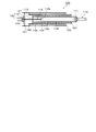
- FIG. 1 shows an overhead wire tension balancer 100.
- the overhead wire tension balancer 100 includes three cylindrical members arranged coaxially.
- the overhead wire tension balancer 100 includes an outer cylinder 101 which is an outermost cylindrical member.
- On the outside of the outer cylinder 101 there is provided a suspension member attaching portion 102 to which a suspension member for support from a pillar (not shown) is connected.
- An annular spring contact portion 103 is provided inside one end (right side in the drawing) of the outer cylinder 101 in the axial direction.
- the spring contact portion 103 has a structure in which ridges protruding in the axial center direction are arranged in an annular shape. The same applies to the other spring contact portions.
- Inside the outer cylinder 101 an intermediate cylinder 104, which is an intermediate cylindrical member, is accommodated coaxially.
- the middle cylinder 104 has a substantially cylindrical shape.
- An outer coil spring 105 is arranged between the middle cylinder 104 and the outer cylinder 101.
- the outer coil spring 105 is divided into a plurality of parts in the axial direction.
- the outer coil spring 105 may have a structure that is not divided. The same applies to the other coil springs.
- One end (the right end in the figure) of the outer coil spring 105 contacts the spring contact portion 103 inside the outer cylinder 101, and the other end (the left end in the figure) of the outer coil spring 105 is provided outside the other end of the middle cylinder 104.
- the annular spring contact portion 106 is in contact.
- the outer coil spring 105 is compressed in a state where there is room for further compression. Has been. The same applies to the other coil springs.
- An annular spring contact portion 107 is provided inside one end portion of the middle cylinder 104.
- the inner cylinder 108 which is the innermost cylindrical member, is accommodated coaxially inside the middle cylinder 104.
- An inner coil spring 109 is disposed between the middle cylinder 104 and the inner cylinder 108.
- One end of the inner coil spring 109 is in contact with the spring contact portion 107 inside the middle cylinder 104, and the other end of the inner coil spring 109 is an annular spring contact portion provided on one outer side of the inner cylinder 108. 110 is in contact.
- a lid member 111 is attached to one end portion of the inner cylinder 108, and an overhead wire attaching portion 112 is fixed to the lid member 111.
- An overhead line (not shown) extending in the right direction in the figure is connected to the overhead line attaching portion 112.
- the overhead line includes an overhead line for power supply, an overhead line for transmitting various signal lines, and a guide line for guiding and pulling these lines.
- a stopper plate 113 which is an example of a restricting member, is attached to the inside of the other end of the inner cylinder 108.
- FIG. 2 shows the stop plate 113.
- the stopper plate 113 is provided with a rectangular opening 114 at the center.
- a long plate 115 which is an example of a longitudinal member, is housed inside the inner cylinder 108.
- a long plate 115 is shown.
- the long plate 115 is composed of long plate pieces 116 and 117.
- the long plate pieces 116 and 117 are the same members, and have a substantially L-shaped structure in which one end portion of an elongated flat plate-like metal plate is bent at a right angle to form bent portions 116a and 117a.
- the long plate 115 is configured by bringing the long plate pieces 116 and 117 into contact with each other back to back.
- the long plate 115 is slidably inserted into the opening 114 of the stop plate 113.
- One end of the long plate 115 is a key-like hook 115a that opens to the left and right when viewed from above.
- the hook part 115a is constituted by bent parts 116a and 117a.
- a bolt hole 118 is provided at the other end of the long plate 115, and the other end of the long plate 115 is fixed to the column mounting portion 120 by a bolt 119 (see FIG. 1) using the bolt hole 118.
- the column attachment portion 120 is fixed to a closing plate 122 attached to the inner side of the outer cylinder 101.
- the column attachment portion 120 is a member for fixing the end portion of the overhead wire tension balancer 100 to a column (concrete column or metal column) (not shown).
- the overhead wire tension balancer 100 is not limited to being fixed to a column, and can be fixed to an appropriate structure.
- Reference numeral 121 in FIG. 1 indicates that when the respective members are housed inside the outer cylinder 101, they are prevented from jumping out to the outside in the axial direction (left side in FIG. 1), and when tension from the overhead wire is applied.
- a U-bolt (having a U-shape when viewed from the axial direction) transmits the force to the closing plate 122.
- FIG. 5 shows a state in which the outer cylinder 101, the outer coil spring 105, the middle cylinder 104, the inner coil spring 109, and the inner cylinder 108 are separated in the axial direction and arranged.
- the overhead wire tension balancer 100 shown in FIG. 1 is assembled as follows. First, the outer coil spring 105 is housed inside the outer cylinder 101. At this time, one end (the right end in the figure) of the outer coil spring 105 is brought into contact with the spring contact portion 103. Next, the middle cylinder 104 is inserted inside the outer coil spring 105, and the other end (the left side in the figure) of the outer coil spring 105 is brought into contact with the spring contact portion 106.
- the inner coil spring 109 is inserted inside the middle cylinder 104, and one end (the right end in the figure) of the inner coil spring 109 is brought into contact with the spring contact portion 107.
- the inner cylinder 108 is inserted inside the inner coil spring 109, and the other end (the left end in the figure) of the inner coil spring 109 is brought into contact with the spring contact portion 110.
- the long plate piece 116 is rotated in the clockwise direction in the drawing with the bent portion 116a as a fulcrum, and the state shown in FIG. 4C is obtained. Then, the other long plate piece 117 is engaged with the opening 114 in the same manner. In this way, the state of FIG. 4D is obtained, and the state in which the long plate 115 is engaged with the stop plate 113 is obtained.
- the long plate 115 can move in the right direction of the drawing with respect to the stop plate 113.
- the opening 114 in FIG. 2 is rectangular and the cross-sectional shape of the long plate 115 is also rectangular, the long plate 115 is slidable inside the opening 114, and the stop plate 113 ( The relative rotation of the long plate 115 with respect to the inner cylinder 108) is suppressed. That is, the stop plate 113 (inner cylinder 108) can move in the left direction in FIG. 4 with respect to the long plate 115 in a state where the stop plate 113 (inner cylinder 108) cannot rotate with respect to the long plate 115. . Further, in the state shown in FIG.
- the hook portion 115a is hooked on the right side surface of the stopper plate 113, so that the long plate 115 cannot move in the left direction in the figure.
- the catch portion 115a is caught on the right side surface of the stop plate 113, so that the stop plate 113 cannot move in the right direction in FIG.
- the long plate pieces 116 and 117 can be removed individually and sequentially from the state shown in FIG. That is, the engagement state of the long plate pieces 116 and 117 with the stopper plate 113 can be released by performing the reverse procedure from the state shown in FIG.
- the fixing U-bolt 121 is inserted, and the outer side (left side in the figure) of the closing plate 122 is pressed by the U-bolt 121 (see FIG. 6). Furthermore, the state shown in FIG. 6 is obtained by attaching the column attaching portion 120 to the long plate 115 with the bolt 119. 6 shows a state viewed from an angle different from that of FIG. 1 by 90 °.
- the long plate 115 is inserted into the rectangular opening 114 in a slidable state (can be inserted and removed), and the rectangular cross-sectional structure of the long plate 115 is the shape of the opening 114. Further, the other end of the long plate 115 (the left end portion in FIGS. 1 and 6) is fixed to a column (not shown) via a column mounting portion 120. When the wire attachment portion 112 moves in the axial direction, the inner cylinder 108 (the overhead wire attachment portion 112) is prevented from rotating.
- the catching portion 115a comes into contact with the right surface of the stopper plate 113 in the drawing, and the inner cylinder 108 moves in the right direction in the drawing. It will be in a state that can not be further.
- the column mounting portion 120 is fixed to a column such as concrete.
- the force acts on the outer cylinder 101 via the inner coil spring 109 and the outer coil spring 105.
- This force is applied to the closing plate 122 from the U-bolt 121 and becomes a force for pushing the closing plate 122 in the right direction in the figure.
- the column attachment portion 120 is fixed to the closing plate 122, as a result, the force that pulls the overhead wire attachment portion 112 in the right direction in the figure is supported by the pillar (not shown) via the column attachment portion 120.
- the inner cylinder 108 that cannot rotate with respect to the long plate 115 does not rotate with respect to a fixed object (in this case, a column not shown).
- the stop plate 113 is provided inside the inner cylinder 108, and the stop plate 113 is relatively non-rotatable with respect to the stop plate 113 and the long plate 115 is penetrated.
- a movable opening 114 is provided.
- the long plate 115 is composed of two L-shaped long plate pieces 116 and 117 whose front ends are bent. The bent portions serve as catching portions 115a, and the stopper plate 113 is detached from the long plate 115. Is suppressed.
- the two long plate pieces 116 and 117 can be individually engaged with the stop plate 113, the manufacturing is simplified.
- FIG. 7 shows a cross-sectional view of the overhead wire tension balancer 200 as viewed from above.
- FIG. 7 shows a step-by-step process in which the inner cylinder 108 is pulled in the right direction of the drawing and the stroke becomes longer as it goes to (A) to (C).
- the telescopic plate 130 includes a hook portion 130a having a structure similar to that of the hook portion 115a of FIG. As shown in FIG. 7, when the inner cylinder 108 moves to the right in the drawing and reaches a certain stage, the hook portion 130 a comes into contact with the stop plate 113, and the telescopic plate 130 extends.
- FIG. 8 shows an exploded perspective view of the telescopic plate 130.
- the extendable plate 130 includes a long plate 140 and long plate pieces 150 and 160.
- the long plate 140 is longer than the long plate pieces 150 and 160, and is provided with a long hole 141 extending in the longitudinal direction.
- a bolt hole 142 is provided at the other end of the long plate 140, and the long plate 140 (expandable plate 130) is fixed to the column attaching portion 120 (see FIG. 7) using the bolt hole 142.
- the long plate pieces 150 and 160 have basically the same structure as the long plate pieces 116 and 117 shown in FIG. 3, and bent portions 150a and 160a are provided at one end. A hook portion 130a is formed by the bent portions 150a and 160a.
- the long plate piece 150 is provided with a bolt hole 151, and the long plate 160 piece is provided with a bolt hole 161. In a state where the long plate 140 is sandwiched between the long plate pieces 150 and 160 in the state shown in the drawing, the bolt 170 is passed through the bolt hole 151, the long hole 141 and the bolt hole 161, and the nut 171 is fastened to the bolt 170.
- the telescopic plate 130 is assembled.
- the bolt 170 can move in the elongated hole 141 in the extending direction, and the fastening state of the bolt 170 and the nut 171 is the long plate pieces 150 and 160 in the assembled state as the stretchable plate 130. Is set to be movable along the extending direction of the long hole 141 with respect to the long plate 140.
- the stop plate 113 shown in FIG. 2 is arranged inside the other end of the inner cylinder 108, and the telescopic plate 130 is passed through the opening 114 of the stop plate 113.
- the stop plate 113 can move relative to the telescopic plate 130 in the left and right directions in FIG. 7, and the stop plate 113 rotates with respect to the telescopic plate 130 about the moving direction. It is said that it cannot be done.
- the assembly of the telescopic plate 130 will be described. First, the long plate pieces 150 and 160 are passed through the opening 114 by the same method as shown in FIG. Next, with the long plate 140 sandwiched between the long plate pieces 150 and 160, the bolt 170 is passed through the bolt hole 151, the long hole 141, and the bolt hole 161, and the nut 171 is fastened to the bolt 170. In this way, the expansion plate 130 is assembled, and the expansion plate 130 is assembled to the overhead wire tension balancer 200. Other assembly operations related to the overhead wire tension balancer 200 are the same as those of the overhead wire tension balancer 100 of FIG.
- the expansion plate 130 is inserted into the rectangular opening 114 (see FIG. 2) in a slidable state (can be inserted and removed), and the rectangular cross-sectional structure of the expansion plate 130 has an opening portion. 114, and the other end portion (left end portion) of the expansion / contraction plate 130 is fixed to a column (not shown) via the column mounting portion 120. Therefore, the overhead wire mounting portion 112 described above is used.
- the inner cylinder 108 (the overhead wire attaching portion 112) is prevented from rotating during movement in the right direction in FIG.
- the overhead wire attaching portion 112 has moved to the right in the drawing to some extent, that is, after the state shown in FIG. At this time, since the bolt 170 can slide in the long hole 141 shown in FIG.
- the hooking portion 130a can further slide in the right direction in FIG. 150 and 160 slide in the right direction in the figure. That is, the hooking portion 130a moves to the right in the drawing together with the stop plate 113, and the telescopic plate 130 extends. This state is shown in FIG. Then, when the extension cannot be performed, the stop plate 113 comes into contact with the catch portion 130a, and the limit point (maximum stroke state) at which the inner cylinder 108 cannot move rightward in FIG. 6 is reached.
- the bolt 170 and the nut 171 are pushed by the stop plate 113 in the left direction in the figure, the long plate pieces 150 and 160 move in the left direction in the figure, and the telescopic plate 130 is contracted.
- the stop plate 113 is further moved to the left, the long plates 150 and 160 are moved in the left direction in the drawing, and finally the middle cylinder 104 and the inner cylinder 108 cannot be moved in the left direction in the drawing. That is, the overhead wire tension balancer 200 is in the most contracted state. In actual use, the tension from the overhead wire and the tension at which the overhead wire tension balancer 200 pulls the overhead wire is balanced in a state between the maximum and minimum strokes.
- the extension plate 130 extends, so that it is possible to earn a distance to pull out the inner cylinder 108 while maintaining the function of preventing the inner cylinder 108 from rotating and retaining. That is, an aerial wire tension balancer corresponding to a long stroke can be obtained.
- FIG. 9 shows an expandable plate 200 that is an example of a long member.
- the telescopic plate 200 has a long plate 210 and long plate pieces 220 and 230.
- the long plate 210 is basically the same member as the long plate 140 of FIG. Although not shown, the long plate 210 is also formed with a long hole similar to the long hole 141 of FIG.
- the long plate pieces 220 and 230 are provided with claw portions 220a and 230a instead of the bent portions 150a and 160a in the long plate pieces 150 and 160 of FIG.
- the claw portion 220a has a projecting structure including a slope portion 220b whose tip is formed obliquely and a step portion 220c, and the step portion 220c is an opening of the stop plate 113 as in the case of the bent portions 150a and 160a.
- the engagement structure is obtained by being caught on the edge of the portion 114. The same applies to the claw portion 230a.
- the long plate 210 and the long plate pieces 220 and 230 are coupled together by bolts 251 and nuts 252.
- the bolt 251 passes through the long hole formed in the long plate 210 so as to be slidable in the longitudinal direction, and is similar to the case of FIG.
- the long plate pieces 220 and 230 are slidable.
- the long plate pieces 220 and 230 are formed by processing a metal plate that can be elastically deformed and bent.
- the dimension of each part is adjusted so that it may be in the state of FIG. 9 (A) when the long plate pieces 220 and 230 are fully slid to the left side of the drawing with respect to the long plate 210. .
- the claw portions 220 a and 230 a are separated by a dimension corresponding to the thickness of the long plate 210.
- the distance L1 between the outer edges of the claw portions 220a and 230a is larger than the dimension L2 of the corresponding portion of the opening 114, and the long plate 210 and the long plate
- the dimensions are adjusted so that the total thickness dimension L3 of the pieces 220 and 230 is smaller than L2.
- the passing dimension L4 in the claw portions 220a and 230a is adjusted so that the claw parts 220a and 230a can pass inside the opening part 114 in the state of FIG. 9B, which is smaller than the corresponding dimension L2 of the opening part 114.
- the long plate pieces 220 and 230 can be individually detached from the stop plate 113 from the state of FIG. That is, the engagement state of the long plate pieces 220 and 230 with the stop plate 113 can be individually released by performing the operation in the reverse procedure from the state shown in FIG. 9C. In this case, the fastening state of the bolt 251 and the nut 252 is released, and the long plate pieces 220 and 230 are detached from the stop plate 113 through the same steps as shown in FIG. 4 (B) ⁇ FIG. 4 (A). Is done. Further, in the state shown in FIG. 9C, the long plate pieces 220 and 230 are bent so as to be close to each other, and through the state shown in FIG. It can also be pulled out.
- the structure shown in FIG. 9 includes the engaging portion that engages with the regulating member when the longitudinal member is caught by the regulating member.
- the engagement portion has a claw portion, and the engagement of the engagement portion with the restriction member occurs when the claw portion is hooked on the edge of the opening formed in the restriction member.
- the plurality of members constituting the longitudinal member are positioned with a gap, and the plurality of members can be elastically deformed in the direction of the gap. Therefore, when the elongated member is pushed into the opening of the restricting member, the engaging portions are displaced in directions close to each other, thereby allowing the engaging portion to enter the opening of the restricting member.
- the engaging portion that has passed through the opening is in a state in which the claw portion is caught by the edge portion of the opening at the stage where the plurality of members constituting the long-shaped member return to its original shape by its own elasticity, and the regulating member It becomes impossible to pull out relatively from the opening part.
- the process of engaging the longitudinal member with the regulating member can be performed with a simpler operation.
- the shape of the opening 114 is not limited to a rectangle, and any shape is acceptable as long as the hook 115a of the long plate 115 can be passed through the opening 115 by the method shown in FIG. 4 and the hook 115a is hooked.
- Other examples of the shape of the opening 114 include an ellipse and a hexagon.
- the bending angle of the bent portions 116 a and 117 a is not limited to 90 °, and may be an angle at which the bent portions 116 a and 117 a are caught on the edge of the opening 114.
- the hook portion 115a may be configured to be hooked on the edge of the opening 114 by providing a protrusion or a claw, instead of being configured by a bent structure exemplified.
- the number of divisions of the long plate 115 is not limited to two divisions, and may be other division numbers such as four divisions.
- the long plate 115 and the telescopic plate 130 may be formed of a cylindrical rod or a prismatic rod.
- the expansion / contraction mechanism of the expansion / contraction plate 130 has a two-stage structure, but it is also possible to employ a three-stage or more expansion / contraction mechanism.
- the cylindrical members arranged coaxially have a triple structure of an outer cylinder, a middle cylinder, and an inner cylinder, but a structure in which two or four or more cylindrical members arranged coaxially are also possible.
- the long plate pieces 220 and 230 may be fixed to the long plate 210. In this case, the stroke cannot be secured as compared with the illustrated structure, but the same function as in the case of FIG. 1 can be obtained.
- the present invention can be used for an overhead wire tension balancer.
Landscapes
- Engineering & Computer Science (AREA)
- Mechanical Engineering (AREA)
- Suspension Of Electric Lines Or Cables (AREA)
- Storage Of Web-Like Or Filamentary Materials (AREA)
- Springs (AREA)
- Toys (AREA)
- Manipulator (AREA)
Description
(構成)
図1には、架空線用テンションバランサ100が示されている。架空線用テンションバランサ100は、同軸配置された3つの円筒部材を備えている。まず、架空線用テンションバランサ100は、一番外側の円筒状の部材である外筒101を備えている。外筒101の外側には、図示しない柱からの支持用の吊り下げ部材が接続される吊り下げ部材取り付け部102が設けられている。外筒101の軸方向における一方(図の右側)の端部内側には、円環形状のばね接触部103が設けられている。ばね接触部103は、軸中心の方向に突出した凸条が円環状に配置された構造を有している。これは、他のばね接触部についても同じである。外筒101の内側には、中間の円筒状の部材である中筒104が同軸状に収められている。中筒104は、略円筒形状を有している。
図5には、外筒101、外側コイルばね105、中筒104、内側コイルばね109、内筒108を軸方向で分離し、並べた状態が示されている。図1に示す架空線用テンションバランサ100の組み立ては、以下のようにして行う。まず、外筒101の内側に外側コイルばね105を収納する。この際、ばね接触部103に外側コイルばね105の一端(図の右端)を接触させる。次に、外側コイルばね105の内側に中筒104を挿入し、外側コイルばね105の他端(図の左側)をばね接触部106に接触させる。次に、内側コイルばね109を中筒104の内側に挿入し、内側コイルばね109の一端(図の右端)をばね接触部107に接触させる。最後に内筒108を内側コイルばね109の内側に差し込み、ばね接触部110に内側コイルばね109の他端(図の左端)を接触させる。
図1の状態において、柱取り付け部120が図示しないコンクリート柱等に固定され、架空線取り付け部112に図示しない架空線が取り付けられた状態を考える。この状態において、図示しない架空線により架空線取り付け部112が図1の右の方向に引かれ、内筒108が図の右の方向に引かれると、外側コイルばね105,内側コイルばね109が縮み、中筒104と内筒108とが、図の右の方向に移動する。この状態が図6に示されている。
以上述べたように、内筒108の内側には、止め板113が設けられ、止め板113には、止め板113に対して回転できない状態で、且つ、長尺プレート115が貫通した状態で相対的に移動可能な開口部114が設けられている。長尺プレート115は、先端が折り曲げられたL字形状の2つの長尺プレート片116,117により構成され、この折り曲げられた部分が引っ掛かり部115aとなり、長尺プレート115からの止め板113の脱落が抑止されている。ここで、2つの長尺プレート片116,117を個別に止め板113に係合可能であるので、製造が簡素化される。
(構成)
本実施形態は、第1の実施形態における長尺プレート115を伸縮する構造とした例である。長尺プレート以外の部分は、第1の実施形態と同じであるので、以下、長尺プレートを伸縮する構造とした点について主に説明する。図7には、架空線用テンションバランサ200を上方向から見た断面図が示されている。図7には、(A)~(C)にゆくに従って、内筒108が図の右の方向に引っ張られストロークが長くなってゆく過程が段階的に示されている。
伸縮プレート130の組み立てについて説明する。まず、図4に示すのと同様な方法により、長尺プレート片150と160を開口部114に通す。次いで、長尺プレート片150と160の間に長尺プレート140を挟んだ状態で、ボルト孔151、長孔141およびボルト孔161にボルト170を通し、ボルト170にナット171を締結する。こうして、伸縮プレート130が組み立てられ、また架空線用テンションバランサ200に伸縮プレート130の組み付けが行われる。架空線用テンションバランサ200に係るその他の組み立て作業は、図1の架空線用テンションバランサ100の場合と同じである。
図7(A)の状態において、柱取り付け部120が図示しないコンクリート柱等に固定され、架空線取り付け部112に図示しない架空線が取り付けられた状態を考える。この状態において、図示しない架空線により架空線取り付け部112が図7の右の方向に引かれ、内筒108が図の右の方向に引かれると、外側コイルばね105,内側コイルばね109が縮み、中筒104と内筒108とが、図の右の方向に移動する。
架空線用テンションバランサ200は、伸縮プレート130が伸びるので、内筒108の回り止め、および抜け止めの機能を維持しつつ、内筒108を引き出す距離を稼ぐことができる。つまり、ロングストロークに対応した架空用線テンションバランサが得られる。
(構成)
本実施形態は、係合部を有した長手形状の部材が弾性変形可能で、弾性変形およびその後の変形が元に戻る作用により、係合部の規制部への係合を行う構成に関する。図9には、長手形状の部材の一例である伸縮プレート200が示されている。伸縮プレート200は、長尺プレート210、長尺プレート片220,230を有している。長尺プレート210は、図8の長尺プレート140と基本的に同じ部材である。図示されていないが、長尺プレート210にも図8の長孔141と同様の長孔が形成されている。長尺プレート片220,230は、図8の長尺プレート片150,160において、折り曲げ部150a,160aの代わりに、爪部220a,230aを備えている。爪部220aは、先端が斜めに成形された斜面部220bと、段差部220cを備えた突起構造を有し、段差部分220cが、折り曲げ部150a,160aの場合と同様に、止め板113の開口部114の縁に引っ掛かり係合構造が得られる構造とされている。これは、爪部230aについても同様である。
図9(A)の状態から、止め板113の開口部114に向かって、長尺プレート片220,230の先端部分を押し込む。ここで、長尺プレート片220,230の右端が、長尺プレート210の右端よりも突出し、爪部220a,230aは、長尺プレート210の厚み分の寸法で離間しており、また、爪部220a,230aは、進む方向の両側が傾斜しているので、爪部220a,230aの先端が開口部114に接触すると、図9(B)に示すように長尺プレート片220,230が弾性変形して内側に撓む。ここで、図9(B)の状態において、爪部220a,230aが開口部114を通過できるように各部の寸法が調整されているので、更に長尺プレート片220,230の先端部分を開口部114に押し込むと、図9(B)の状態から、図9(C)の状態に移ることができる。そして、図9(C)の状態において、撓んだ長尺プレート片220,230が自身の弾性で元の形状に戻り、その撓みが解消される。ここで、L1>L2と設定されているので、図9(C)の状態において、爪部220a,230aの段差部分が開口部114の縁に引っ掛かり、長尺プレート片220,230に対して、止め板113が図の右の方向に動けなくなる。この状態において、長尺プレート210に対して、長尺プレート片220,230がスライドするので、第2の実施形態の場合と同様の機能を得ることができる。なお、回り止めの機能が得られる点は、第1の実施形態および第2の実施形態の場合と同じである。
止め板113の開口部114に伸縮プレート200を係合させるための作業が、止め板113の開口部114に伸縮プレート200を押し込むだけでよいので、作業の負担が軽減される。このため、製造コストを抑えることができる。
開口部114の形状は矩形に限定されず、図4に示す方法で長尺プレート115の引っ掛かり部115aを開口部115に通すことができ、且つ、引っ掛かり部115aが引っ掛かる形状であればよい。開口部114の形状の他の例としては、楕円形や六角形等が挙げられる。折り曲げ部116a,117aの折り曲げ角度は、90°に限定されず、折り曲げ部116a,117aが開口部114の縁に引っ掛かる角度であればよい。また、引っ掛かり部115aを例示した折り曲げ構造によって構成するのでなく、突起部や爪を設けることで開口部114の縁に引っ掛かるような構造とすることもできる。
Claims (5)
- 同軸配置された複数の筒部材を有し、
前記複数の筒部材の最も内側の筒部材の内側に延在した長手形状の部材と、
前記最も内側の筒部材の内側に設けられ、前記長手形状の部材がその長手方向に移動可能で、前記長手形状の部材の前記長手方向を軸とする回転を規制し、且つ、前記長手形状の部材を前記最も内側の筒部材から完全に引き抜くことができない状態で前記長手形状の部材と係合する規制部材と
を備え、
前記長手形状の部材は、複数の部材から構成されており、
前記複数の部材のそれぞれは前記規制部材に係合する係合部を備え、
前記複数の部材を、前記規制部材に個別に係合させることで、前記長手形状の部材の前記規制部材への係合が行われていることを特徴とする架空線用テンションバランサ。 - 前記複数の部材は、先端が折り曲げられたL字型の板状の第1の部材および第2の部材であることを特徴とする請求項1に記載の架空線用テンションバランサ。
- 前記長手形状の部材が前記規制部材に係合している状態において、前記長手形状の部材を前記複数の部材に分解し、前記複数の部材のぞれぞれの前記規制部材への係合を個別に解除できることを特徴とする請求項1または2に記載の架空線用テンションバランサ。
- 前記複数の部材が弾性変形することで前記係合が行われることを特徴とする請求項1に記載の架空線用テンションバランサ。
- 前記長手形状の部材は、伸縮が可能であることを特徴とする請求項1~4のいずれか一項に記載の架空線用テンションバランサ。
Priority Applications (4)
| Application Number | Priority Date | Filing Date | Title |
|---|---|---|---|
| IN2873KON2014 IN2014KN02873A (ja) | 2012-09-25 | 2013-08-21 | |
| US14/405,297 US9531178B2 (en) | 2012-09-25 | 2013-08-21 | Overhead wire tension balancer |
| JP2014538283A JP6076992B2 (ja) | 2012-09-25 | 2013-08-21 | 架空線用テンションバランサ |
| KR1020147034551A KR102049134B1 (ko) | 2012-09-25 | 2013-08-21 | 가공선용 텐션 밸런서 |
Applications Claiming Priority (2)
| Application Number | Priority Date | Filing Date | Title |
|---|---|---|---|
| JP2012-210385 | 2012-09-25 | ||
| JP2012210385 | 2012-09-25 |
Publications (1)
| Publication Number | Publication Date |
|---|---|
| WO2014050374A1 true WO2014050374A1 (ja) | 2014-04-03 |
Family
ID=50300208
Family Applications (1)
| Application Number | Title | Priority Date | Filing Date |
|---|---|---|---|
| PCT/JP2013/072261 Ceased WO2014050374A1 (ja) | 2012-09-25 | 2013-08-21 | 架空線用テンションバランサ |
Country Status (6)
| Country | Link |
|---|---|
| US (1) | US9531178B2 (ja) |
| JP (1) | JP6076992B2 (ja) |
| KR (1) | KR102049134B1 (ja) |
| CN (2) | CN203727199U (ja) |
| IN (1) | IN2014KN02873A (ja) |
| WO (1) | WO2014050374A1 (ja) |
Cited By (1)
| Publication number | Priority date | Publication date | Assignee | Title |
|---|---|---|---|---|
| CN115800133A (zh) * | 2022-12-06 | 2023-03-14 | 杭州景业智能科技股份有限公司 | 伸缩装置用线缆管理结构 |
Families Citing this family (10)
| Publication number | Priority date | Publication date | Assignee | Title |
|---|---|---|---|---|
| US9531178B2 (en) * | 2012-09-25 | 2016-12-27 | Nhk Spring Co., Ltd | Overhead wire tension balancer |
| CN105932626B (zh) * | 2016-05-30 | 2018-01-09 | 安徽威龙电力器材有限公司 | 一种具有高韧性的电力金具 |
| CN107653814B (zh) * | 2016-09-23 | 2019-08-02 | 扬州市旅游日用品制造总厂 | 太阳能供电电线杆电线防撞装置 |
| USD859110S1 (en) * | 2017-02-10 | 2019-09-10 | Nagaki Seiki Co., Ltd. | Wire-tensioning device for live-wire separating tool |
| USD855427S1 (en) * | 2017-02-10 | 2019-08-06 | Nagaki Seiki Co., Ltd. | Wire-tensioning device for live-wire separating tool |
| JP7427473B2 (ja) * | 2020-02-27 | 2024-02-05 | 日本発條株式会社 | 架空線用テンションバランサ |
| CN213367257U (zh) * | 2020-10-09 | 2021-06-04 | 青岛长淮机械有限公司 | 防松拉线器 |
| JP7685451B2 (ja) * | 2022-02-14 | 2025-05-29 | 日本発條株式会社 | 架空線用テンションバランサ |
| CN118174223B (zh) * | 2024-02-21 | 2024-09-27 | 山东大学 | 一种输电线限位装置及方法 |
| CN118412811B (zh) * | 2024-07-03 | 2024-09-10 | 北华大学 | 一种电气绝缘电缆安装组件 |
Citations (5)
| Publication number | Priority date | Publication date | Assignee | Title |
|---|---|---|---|---|
| JPH09207629A (ja) * | 1996-01-31 | 1997-08-12 | Sanwa Tekki Corp | ばね式テンションバランサ |
| JPH115462A (ja) * | 1997-06-13 | 1999-01-12 | East Japan Railway Co | トロリ線引止装置 |
| JPH1148834A (ja) * | 1997-08-06 | 1999-02-23 | Dengiyou:Kk | 架空線用テンションバランサ |
| JP2000158979A (ja) * | 1998-11-25 | 2000-06-13 | Nhk Spring Co Ltd | 架空線用テンションバランサ |
| JP2010280320A (ja) * | 2009-06-05 | 2010-12-16 | Sei Nishimura | 架空線用テンションバランサ |
Family Cites Families (8)
| Publication number | Priority date | Publication date | Assignee | Title |
|---|---|---|---|---|
| US1222480A (en) * | 1916-06-20 | 1917-04-10 | Guy Window Smith | Tow-line connector. |
| US2128030A (en) * | 1937-09-03 | 1938-08-23 | Joseph J Koleno | Tightener for cables |
| WO1999012762A1 (fr) * | 1996-03-04 | 1999-03-18 | Central Japan Railway Company | Dispositif tendeur de cable aerien |
| JP2001020987A (ja) * | 1999-07-08 | 2001-01-23 | Nhk Spring Co Ltd | ガススプリング |
| JP5028239B2 (ja) * | 2007-12-06 | 2012-09-19 | 東北電力株式会社 | テンションバランサー |
| JP5036063B2 (ja) * | 2008-06-10 | 2012-09-26 | 日本発條株式会社 | 架空線用テンションバランサ装置および架空線用テンションバランサ防水カバー |
| JP4861398B2 (ja) * | 2008-12-29 | 2012-01-25 | 日本発條株式会社 | 架空線用テンションバランサ及び架空線用テンションバランサ設置補助装置 |
| US9531178B2 (en) * | 2012-09-25 | 2016-12-27 | Nhk Spring Co., Ltd | Overhead wire tension balancer |
-
2013
- 2013-08-21 US US14/405,297 patent/US9531178B2/en not_active Expired - Fee Related
- 2013-08-21 WO PCT/JP2013/072261 patent/WO2014050374A1/ja not_active Ceased
- 2013-08-21 IN IN2873KON2014 patent/IN2014KN02873A/en unknown
- 2013-08-21 KR KR1020147034551A patent/KR102049134B1/ko not_active Expired - Fee Related
- 2013-08-21 JP JP2014538283A patent/JP6076992B2/ja active Active
- 2013-09-25 CN CN201320593367.XU patent/CN203727199U/zh not_active Expired - Lifetime
- 2013-09-25 CN CN201310440717.3A patent/CN103661004B/zh not_active Expired - Fee Related
Patent Citations (5)
| Publication number | Priority date | Publication date | Assignee | Title |
|---|---|---|---|---|
| JPH09207629A (ja) * | 1996-01-31 | 1997-08-12 | Sanwa Tekki Corp | ばね式テンションバランサ |
| JPH115462A (ja) * | 1997-06-13 | 1999-01-12 | East Japan Railway Co | トロリ線引止装置 |
| JPH1148834A (ja) * | 1997-08-06 | 1999-02-23 | Dengiyou:Kk | 架空線用テンションバランサ |
| JP2000158979A (ja) * | 1998-11-25 | 2000-06-13 | Nhk Spring Co Ltd | 架空線用テンションバランサ |
| JP2010280320A (ja) * | 2009-06-05 | 2010-12-16 | Sei Nishimura | 架空線用テンションバランサ |
Cited By (2)
| Publication number | Priority date | Publication date | Assignee | Title |
|---|---|---|---|---|
| CN115800133A (zh) * | 2022-12-06 | 2023-03-14 | 杭州景业智能科技股份有限公司 | 伸缩装置用线缆管理结构 |
| CN115800133B (zh) * | 2022-12-06 | 2024-10-29 | 杭州景业智能科技股份有限公司 | 伸缩装置用线缆管理结构 |
Also Published As
| Publication number | Publication date |
|---|---|
| IN2014KN02873A (ja) | 2015-05-08 |
| CN103661004B (zh) | 2017-04-26 |
| US20150155693A1 (en) | 2015-06-04 |
| KR102049134B1 (ko) | 2019-11-26 |
| JPWO2014050374A1 (ja) | 2016-08-22 |
| US9531178B2 (en) | 2016-12-27 |
| CN103661004A (zh) | 2014-03-26 |
| KR20150060606A (ko) | 2015-06-03 |
| CN203727199U (zh) | 2014-07-23 |
| JP6076992B2 (ja) | 2017-02-08 |
Similar Documents
| Publication | Publication Date | Title |
|---|---|---|
| JP6076992B2 (ja) | 架空線用テンションバランサ | |
| JP5580473B2 (ja) | キャプティブパネルファスナアセンブリ | |
| US11242014B2 (en) | Cable spacer arrangement | |
| EP3361109B1 (en) | Control cable | |
| JP2017153260A (ja) | 固定部材付きワイヤハーネス | |
| US11465577B2 (en) | Spring element for fastening an air bag module to a vehicle steering wheel, and steering wheel assembly comprising such a spring element | |
| JP5825716B2 (ja) | 引張ばねユニット | |
| WO2011105203A1 (ja) | ケーブル式操作装置 | |
| US10995790B2 (en) | Elongate member assembly | |
| WO2022158435A1 (ja) | クランプ及びワイヤハーネス | |
| US10703337B2 (en) | Wiper arm and windscreen wiper system for a motor vehicle | |
| KR101354602B1 (ko) | 파이프 부재용 락킹장치 | |
| JP6346506B2 (ja) | 仮復旧用電柱バンド | |
| JP6682902B2 (ja) | えい航ケーブル用整流装置 | |
| JP2009024792A (ja) | 機器作動用ケーブルの取付構造 | |
| CN204961654U (zh) | 弹簧及其固定装置 | |
| JP5846352B2 (ja) | 橋梁の保護管可動支持構造 | |
| JP2001069655A (ja) | 電線収容装置 | |
| JPH11336715A (ja) | ケーブル用クランプ構造 | |
| JP2013206870A (ja) | スイッチ装置 | |
| KR101107128B1 (ko) | 스프링모듈 및 이를 구비하는 슬라이드 장치 | |
| CN108131419B (zh) | 减振装置 | |
| KR102164636B1 (ko) | 차량용 도어 슬램 범퍼 | |
| JP2016201387A (ja) | ノイズフィルタ及びノイズフィルタ用位置決め部材 | |
| CN108757788A (zh) | 弹簧及其固定装置 |
Legal Events
| Date | Code | Title | Description |
|---|---|---|---|
| 121 | Ep: the epo has been informed by wipo that ep was designated in this application |
Ref document number: 13840743 Country of ref document: EP Kind code of ref document: A1 |
|
| ENP | Entry into the national phase |
Ref document number: 2014538283 Country of ref document: JP Kind code of ref document: A |
|
| WWE | Wipo information: entry into national phase |
Ref document number: 14405297 Country of ref document: US |
|
| ENP | Entry into the national phase |
Ref document number: 20147034551 Country of ref document: KR Kind code of ref document: A |
|
| NENP | Non-entry into the national phase |
Ref country code: DE |
|
| 122 | Ep: pct application non-entry in european phase |
Ref document number: 13840743 Country of ref document: EP Kind code of ref document: A1 |