WO2014049813A1 - 保護シート積層体および保護シート貼り付け方法 - Google Patents
保護シート積層体および保護シート貼り付け方法 Download PDFInfo
- Publication number
- WO2014049813A1 WO2014049813A1 PCT/JP2012/075018 JP2012075018W WO2014049813A1 WO 2014049813 A1 WO2014049813 A1 WO 2014049813A1 JP 2012075018 W JP2012075018 W JP 2012075018W WO 2014049813 A1 WO2014049813 A1 WO 2014049813A1
- Authority
- WO
- WIPO (PCT)
- Prior art keywords
- protective sheet
- sheet
- auxiliary
- protected surface
- protective
- Prior art date
- Legal status (The legal status is an assumption and is not a legal conclusion. Google has not performed a legal analysis and makes no representation as to the accuracy of the status listed.)
- Ceased
Links
Images




Classifications
-
- G—PHYSICS
- G02—OPTICS
- G02B—OPTICAL ELEMENTS, SYSTEMS OR APPARATUS
- G02B27/00—Optical systems or apparatus not provided for by any of the groups G02B1/00 - G02B26/00, G02B30/00
- G02B27/0006—Optical systems or apparatus not provided for by any of the groups G02B1/00 - G02B26/00, G02B30/00 with means to keep optical surfaces clean, e.g. by preventing or removing dirt, stains, contamination, condensation
-
- G—PHYSICS
- G02—OPTICS
- G02B—OPTICAL ELEMENTS, SYSTEMS OR APPARATUS
- G02B1/00—Optical elements characterised by the material of which they are made; Optical coatings for optical elements
- G02B1/10—Optical coatings produced by application to, or surface treatment of, optical elements
- G02B1/14—Protective coatings, e.g. hard coatings
Definitions
- the present invention relates to a protective sheet laminate for attaching a protective sheet to a protected surface of an electronic device and a protective sheet attaching method.
- Patent Document 1 there is a protective sheet laminate in which an auxiliary sheet larger than the protective sheet is attached to the front side surface of the protective sheet in order to make it easy to attach the protective sheet to a protected surface such as a liquid crystal display or a touch panel (for example, , See Patent Document 1).
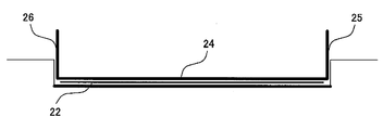
- auxiliary sheet is larger than the protective sheet, for example, when there is a step around the protected surface as shown in FIG. There is a problem that positioning becomes difficult and air bubbles easily enter between the protected surface and the protective sheet.
- the present invention has an object of providing a protective sheet laminate and a protective sheet attaching method capable of appropriately attaching a protective sheet to a protected surface of an electronic device.
- the first configuration example is a protective sheet laminate for attaching a protective sheet to a protected surface of an electronic device, and includes a protective sheet, an auxiliary sheet, and at least one gripping portion.
- the auxiliary sheet is affixed to the protective sheet so as to cover the front side surface of the protective sheet.
- the grip portion extends from the auxiliary sheet in the direction opposite to the protective sheet.
- the “front side surface” of the protective sheet is a surface that is exposed after the protective sheet is attached to the protected surface.
- “extending from the auxiliary sheet in the direction opposite to the protective sheet” is typically perpendicular to the protective sheet. The direction may be different.
- the auxiliary sheet may be subjected to a bending process so as to be easily bent at a predetermined folding line. And it may be constituted so that a part of the auxiliary sheet may function as the grip part by bending the auxiliary sheet at a folding line. Thereby, the thickness of the protective sheet laminated body before use can be suppressed.
- the protective sheet is rectangular
- the auxiliary sheet has a rectangular rectangular part having a size corresponding to the protective sheet
- the gripping part is on the side of the rectangular part and away from the corners at both ends of the side. It may be provided at a different position.
- the protective sheet may be rectangular, and the auxiliary sheet may have a rectangular rectangular portion having a size corresponding to the protective sheet.
- a first grip portion and a second grip portion are provided on the first side of the rectangular portion and on the second side facing the first side, respectively.
- the length of the boundary portion may be shorter than the length of the boundary portion between the second side and the second grip portion.
- a hole may be provided in the grip portion. This makes it difficult for the finger holding the grip portion to slip.
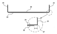
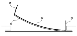
- the folding line of the auxiliary sheet may be provided at a position slightly away from the protective sheet. Thereby, for example, even when there is a gap around the surface to be protected as shown in FIG. 14, it is possible to prevent the protective sheet from being caught in the gap.
- the protective sheet laminate may further include a release sheet attached to the protective sheet so as to cover the back side surface of the protective sheet.
- the peeling sheet may be comprised so that the said peeling sheet can be isolate
- the protective sheet laminate may further include a release sheet attached to the protective sheet so as to cover the back side surface of the protective sheet.
- the outer edge of a peeling sheet may be an outer side rather than the outer edge of a protection sheet and an auxiliary sheet over the perimeter.
- the protective sheet is rectangular, and the outer edge of the auxiliary sheet excluding the grip portion may be inside the outer edge of the protected surface over the entire circumference. Thereby, for example, even when there is a step around the protected surface as shown in FIG. 11, the auxiliary sheet may become an obstacle when the end portion of the protective sheet is brought into contact with the protected surface. Absent.
- the adhesive force between the protective sheet and the auxiliary sheet may be adjusted to be smaller than the adhesive force between the protective sheet and the protected surface.
- the protective sheet and the auxiliary sheet are attached via a weak adhesive sheet, and the adhesive force between the protective sheet and the protected surface is smaller than the adhesive force between the auxiliary sheet and the weak adhesive sheet, and The adhesive strength between the protective sheet and the weak adhesive sheet may be adjusted to be larger.
- the second configuration example is a protective sheet attaching method in which a protective sheet is attached to a protected surface of an electronic device using a protective sheet laminate, and at least a back side surface of the protective sheet is gripped by a grip portion.
- a step of bringing a part into contact with the surface to be protected, a step of attaching the protective sheet laminate to the surface to be protected so that the entire back side of the protective sheet adheres to the surface to be protected, and an auxiliary sheet from the protective sheet laminate A step of peeling
- a third configuration example is a protective sheet attaching method in which a protective sheet is attached to a protected surface of an electronic device using a protective sheet laminate, and at least a part of the back side surface of the protective sheet is applied to the protected surface.
- a fourth configuration example is a protective sheet attaching method in which a protective sheet is attached to a surface to be protected of an electronic device using a protective sheet laminate, and the auxiliary sheet is folded at a fold line so that The step of functioning as a grip portion, the step of gripping the grip portion and bringing at least a part of the back side surface of the protective sheet into contact with the protected surface, and the entire back side surface of the protective sheet sticking to the protected surface And a step of attaching the protective sheet laminate to the surface to be protected and a step of peeling the auxiliary sheet from the protective sheet laminate.
- the fifth configuration example is a protective sheet affixing method for adhering a protective sheet to a protected surface of an electronic device using a protective sheet laminate, the grip part being gripped, and a grip part in a rectangular part being provided.
- the step of aligning the corners of both ends of the first side with the corners of the protected surface, and the contact for bringing a part of the back side surface of the protective sheet close to the first side of the rectangular portion into contact with the protected surface A step, a step of attaching the protective sheet laminate to the surface to be protected, and a step of peeling the auxiliary sheet from the protective sheet laminate so that the entire back side surface of the protective sheet is attached to the surface to be protected.
- a sixth configuration example is a protective sheet attaching method for attaching a protective sheet to a surface to be protected of an electronic device using a protective sheet laminate, and a rectangular portion by grasping a first grip portion and a second grip portion. A part of the back side surface of the protective sheet close to the first side of the sheet is brought into contact with the surface to be protected, and at least the second grip part is finally stuck to the surface to be protected while holding the second gripping part. Attaching the protective sheet laminate to the surface to be protected from the first side toward the second side, and a step of peeling a part of the auxiliary sheet from the protective sheet by twisting the second gripping part, A step of grasping the second grip portion and peeling the entire auxiliary sheet from the protective sheet laminate.
- the protective sheet can be appropriately attached to the protected surface of the electronic device.
- Sectional drawing which shows a mode that the protection sheet 22 is affixed on the to-be-protected surface shown in FIG.
- Sectional view of an electronic device with a gap around the protected surface The figure which shows the cross section of the auxiliary sheet
- the information processing apparatus 10 shown in FIG. 1 is provided with a display device (for example, a liquid crystal display), and a touch panel 11 is provided on the screen of the display device.
- a display device for example, a liquid crystal display
- a touch panel 11 is provided on the screen of the display device.
- a protective sheet laminate 20 shown in FIG. 2 is used.
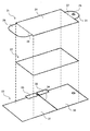
- the protection sheet laminate 20 roughly has a structure in which three sheets (auxiliary sheet 21, protection sheet 22, and release sheet 23) are laminated as shown in FIG.
- the protective sheet 22 is a transparent sheet (or film) that is attached to the surface of the touch panel 11 in order to protect the surface of the touch panel 11 from scratches and the like.
- the size of the protective sheet 22 is slightly smaller than the size of the surface (exposed portion) of the touch panel 11.
- the auxiliary sheet 21 is affixed to the front side surface of the protective sheet 22 (the surface exposed after the protective sheet 22 is affixed to the touch panel 11) to facilitate the affixing operation of the protective sheet 22 Is provided.
- a transparent sheet or film is used as the auxiliary sheet 21, but the auxiliary sheet 21 does not need to be transparent.
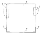
- the auxiliary sheet 21 includes a rectangular portion 24 having a size corresponding to the protective sheet 22 and two grip portions (a first grip portion 25 and a second grip portion 26).
- the first fold line 27, which is a boundary line between the rectangular portion 24 and the first grip portion 25, is subjected to a bending process so that the auxiliary sheet 21 can be easily bent at the first fold line 27. Yes.
- the second folding line 28 that is a boundary line between the rectangular portion 24 and the second gripping portion 26 is similarly bent. Typical examples of the bending process include a perforation and a V-shaped groove.
- a hole 29 is provided in the first grip portion 25.
- the size of the rectangular portion 24 is preferably the same as or slightly smaller than the size of the surface (exposed portion) of the touch panel 11.
- the release sheet 23 is affixed to the back side surface of the protective sheet 22 and is provided to prevent foreign matter from adhering to the back side surface of the protective sheet 22 until the start of the affixing operation of the protective sheet 22. It has been.
- the release sheet 23 is divided into two release portions (first release portion 30 and second release portion 31) with a separation line 34 that crosses almost the center of the protective sheet 22 as a boundary.
- a first label 32 and a second label 33 are attached to the second peeling portion 31, respectively.
- the first label 32 and the second label 33 have a role of guiding the user to start peeling from a portion near the separation line 34 when the user peels off the first peeling portion 30 and the second peeling portion 31.
- the first label 32 and the second label 33 may be, for example, a paper seal.
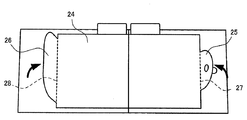
- the auxiliary sheet 21 is bent at the first fold line 27 and the second fold line 28 so that the first grip part 25 and the second grip part 26 are on the front side (that is, as viewed from the auxiliary sheet 21). It extends in the direction opposite to the protective sheet. At this time, it is preferable that the auxiliary sheet 21 is bent at a substantially right angle at the first fold line 27 and the second fold line 28.
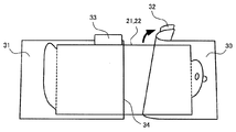
- the first label 32 is grasped and the first peeling portion 30 is peeled off from the protective sheet laminate 20.
- the 1st peeling part 30 will peel from the part close
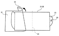
- the second label 33 is grasped and the second peeling portion 31 is peeled off from the protective sheet laminate 20. Also in this case, since the second peeling portion 31 is peeled off from the portion close to the separation line 34, the protective sheet 22 is not peeled off together with the second peeling portion 31.
- the second peeling portion 31 is peeled off, the second label 33 is gripped by one hand (for example, the left hand) and the first gripping portion 25 is gripped by the other hand (for example, the right hand) to thereby attach the protective sheet 22 to the protective sheet 22.
- the 2nd peeling part 31 can be peeled without touching at all. Therefore, fingerprints can be prevented from adhering to the back side surface of the protective sheet 22.
- the hole 29 is provided in the 1st grip part 25, the hand holding the 1st grip part 25 slips in the middle or after peeling of the 2nd peel part 31, and a protective sheet laminated body 20 is not dropped. Therefore, it is possible to prevent dirt from adhering to the back side surface of the protective sheet 22 due to falling.
- the first grip portion 25 is gripped by one hand (for example, the right hand) and the second grip portion 26 is gripped by the other hand (for example, the left hand).
- a part of the back side surface of the protective sheet 22 close to the right side of the rectangular part 24 is made to match the right side of the touch panel 11 with the side where the one grip part 25 is provided (hereinafter referred to as the right side for convenience).
- the first grip portion 25 is provided at a position away from the corners (upper right corner and lower right corner) of the rectangular portion 24, the position of the corner of the rectangular portion 24 (substantially, the protective sheet) is provided to the user. Can be easily and accurately grasped. Therefore, it becomes easy for the user to position the rectangular portion 24 (as a result, position the protective sheet 22).
- the hole 29 is provided in the 1st grip part 25, the hand holding the 1st grip part 25 does not slip, but can position correctly.
- the other hand for example, the right hand
- the back side surface of the protective sheet 22 is gradually attached to the surface of the touch panel 11 so as to slide the surface of the rectangular portion 24 toward the surface.
- the back side surface of the protective sheet 22 is covered with an adhesive, but its adhesive strength is suppressed to such an extent that it can be easily re-applied. Therefore, at this stage, the user can easily peel off the protective sheet 22 from the touch panel 11 simply by pulling up the second grip 26, and can re-apply the protective sheet 22 from the state of FIG.
- the protective sheet laminate 20 is particularly effective for an electronic device having a step due to a housing or a frame member around a protected surface (touch panel, display, etc.) as shown in FIG.
- the protective sheet laminate 20 is provided with the first grip portion 25 and the second grip portion 26, and these grip portions are on the front side (that is, when viewed from the auxiliary sheet 21, the protective sheet 22. (Opposite direction). Therefore, even when there is a step as shown in FIG. 11, the user starts to attach the protective sheet 22 to the protected surface as shown in FIG.
- the auxiliary sheet 21 does not get in the way until the entire back side is pasted. Therefore, mixing of bubbles between the protected surface and the protective sheet 22 can be suppressed, and the protective sheet 22 can be appropriately attached.
- the protective sheet laminate 20 is particularly effective for an electronic device having a gap due to a housing or a frame member around the protected surface.
- the protective sheet laminate 20 has an end portion of the protective sheet 22 slightly inside the boundary line between the rectangular portion 24 and the first grip portion 25 (that is, the first folding line 27). It is comprised so that it may be located in. Therefore, as shown in FIG. 16, when a part of the back side surface of the protective sheet 22 is brought into contact with the surface to be protected, the end portion of the protective sheet 22 does not come too close to the gap. Therefore, it can prevent that the edge part of the protection sheet 22 is pinched
- the surface to be protected is a resistive film type touch panel, it is important to prevent the end of the protective sheet 22 from being caught if the end of the protective sheet 22 is caught in the gap.
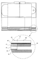
- the protective sheet laminate 20 roughly has a structure in which three sheets (auxiliary sheet 21, protective sheet 22, and release sheet 23) are laminated. 21 and the protective sheet 22 are attached via a weak adhesive sheet 41.
- the weak adhesive sheet 41 is a sheet that has weak adhesive force (or adsorption force) on both sides.
- the entire back side surface of the auxiliary sheet 21 is covered with an adhesive 40 having a strong adhesive force.
- the weak adhesive sheet 41 is affixed on the rectangular part 24 of the auxiliary sheet 21 via the adhesive 40, and the grip part (the first grip part 25, the second grip part 26) of the auxiliary sheet 21 is attached.
- a cover sheet 42 is attached via an adhesive 40. The cover sheet 42 is provided to prevent the adhesive 40 from touching the user's hand when the user grips the grip portion.
- the back side surface of the protective sheet 22 is covered with an adhesive 43.
- the peeling sheet 23 (the 1st peeling part 30 and the 2nd peeling part 31) is affixed on the back side surface of the protection sheet 22 via the adhesive agent 43.
- the adhesive force of the adhesive 43 is stronger than the adhesive force (or adsorption force) of the weak adhesive sheet 41 and is smaller than the adhesive force of the adhesive 40.
- the adhesive force (or adsorbing force) of the weak adhesive sheet 41 and the adhesive force of the adhesive 43 can be easily reapplied during the attaching operation of the protective sheet 22, and the entire back side surface of the protective sheet 22 can be applied. Is attached to the protected surface so that the protective sheet 22 is not peeled off together with the auxiliary sheet 21 (and the weak adhesive sheet 41).
- the grip portions (the first grip portion 25 and the second grip portion 26) extending toward the front side (that is, the direction opposite to the protective sheet as viewed from the auxiliary sheet 21).
- the members that become the gripping portions are attached to the auxiliary sheet 21 with an adhesive or the like. You may do it.
- first grip portion 25 and the second grip portion 26 are provided.
- one grip portion for example, the first grip portion 25 or the first grip portion 25
- Only one of the two grip portions 26 may be provided.
- three or more grip portions may be provided.
- the grip portion is provided on the side of the rectangular portion 24.
- the grip portion may be provided at a position away from the side of the rectangular portion 24.
- the protection sheet 22 and the rectangular part 24 are rectangles, if the to-be-protected surface is shapes other than a rectangle, naturally, the shape of the protecting sheet 22 and the rectangular part 24 is also the shape of a to-be-protected surface. It should be shaped according to the shape.
- seat 21 is affixed on the front side surface of the protection sheet 22 via the weak adhesive sheet 41
- a protection sheet The auxiliary sheet 21 may be affixed to the front side surface of 22.
- the protective sheet 22 is affixed on the touchscreen 11 toward the 2nd grip part 26 from the 1st grip part 25, in other embodiment, the 2nd grip part 26 is 1st grip part.
- the protective sheet 22 may be attached to the touch panel 11 toward 25.
- the 1st grip part 25 and the 2nd grip part 26 are each provided in the left and right sides of the rectangular part 24, in other embodiment, the 1st grip part 25 and the 2nd grip part 26 may be provided on the upper and lower sides of the rectangular portion 24, respectively.
Landscapes
- Physics & Mathematics (AREA)
- General Physics & Mathematics (AREA)
- Optics & Photonics (AREA)
- Laminated Bodies (AREA)
Description
本発明は、電子機器の被保護面に保護シートを貼り付けるための保護シート積層体および保護シート貼り付け方法に関する。
従来、液晶ディスプレイやタッチパネル等の表面である被保護面に保護シートを貼り付け易くするために、保護シートの表側面に、保護シートよりも大きな補助シートを張り付けた保護シート積層体がある(例えば、特許文献1を参照。)。
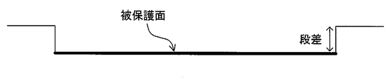
しかしながら、補助シートが保護シートよりも大きいと、例えば図11のように被保護面の周囲に段差があるような場合に、保護シートの端部を被保護面に当接させる際に補助シートが邪魔になってしまい、位置決めが困難になったり、被保護面と保護シートの間に気泡が入りやすいという問題がある。
本発明は、電子機器の被保護面に保護シートを適切に貼り付けることが可能な保護シート積層体および保護シート貼り付け方法を提供することを目的する。
上記目的を達成するために、例えば下記の構成を採用し得る。
第1の構成例は、電子機器の被保護面に保護シートを貼り付けるための保護シート積層体であって、保護シートと、補助シートと、少なくとも1つの掴み部とを備える。補助シートは、保護シートの表側面を覆うように保護シートに貼り付けられている。掴み部は、補助シートから、保護シートとは反対方向に延びている。
なお、保護シートの「表側面」とは、保護シートが被保護面に貼り付けられた後に露出する側の面である。また、「補助シートから保護シートとは反対方向に延びている」とは、典型的には保護シートに対して垂直方向であるが、垂直方向に限らず、例えば保護シートに対して45度傾いた方向であってもよい。
また、補助シートには、所定の折り曲げ線において容易に折り曲げられるようにするための折り曲げ加工が施されていてもよい。そして、折り曲げ線において当該補助シートを折り曲げることによって、当該補助シートの一部が前記掴み部として機能するように構成されていてもよい。これにより、使用前の保護シート積層体の厚みを抑えることができる。
なお、折り曲げ加工の典型例としては、ミシン目や、V字型の溝が挙げられるが、これらに限定されない。
また、保護シートは矩形であり、補助シートは、保護シートに対応する大きさの矩形の矩形部を有し、掴み部は、矩形部の辺上で、かつ、当該辺の両端の角から離れた位置に設けられていてもよい。これにより、保護シート(または補助シートの矩形部)の角の位置をユーザが把握し易くなるため、保護シートの位置決めが容易になる。
また、保護シートは矩形であり、補助シートは、保護シートに対応する大きさの矩形の矩形部を有していてもよい。そして、矩形部の第1辺上と、当該第1辺に対向する第2辺上には、第1掴み部および第2掴み部がそれぞれ設けられており、第1辺と第1掴み部の境界部分の長さが、第2辺と第2掴み部の境界部分の長さよりも短くてもよい。これにより、第1辺の両端の角の位置をユーザが把握し易くなるため、第1辺の両端の角の位置を参照して、容易に保護シートの位置決めを行うことができる。また、第2掴み部が第2辺の端部の角の近くまで延びているので、第2掴み部をひねることによって、保護シートから補助シートを容易に剥がすことができる。
また、掴み部には穴が設けられていてもよい。これにより、掴み部を掴んでいる指が滑りにくくなる。
また、補助シートの折り曲げ線は、保護シートから僅かに離れた位置に設けられていてもよい。これにより、例えば図14のように被保護面の周囲に隙間があるような場合であっても、当該隙間に保護シートが挟まってしまうのを防止することができる。
また、保護シート積層体は、保護シートの裏側面を覆うように当該保護シートに貼り付けられた剥離シートをさらに備えてもよい。そして、剥離シートには、保護シートを横切る分離線において当該剥離シートを少なくとも2つに分離可能に構成されていてもよい。これにより、保護シート積層体から剥離シートを剥がす際に、当該剥離シートと一緒に保護シートが剥がれてしまうのを防止することができる。
また、保護シート積層体は、前記保護シートの裏側面を覆うように当該保護シートに貼り付けられた剥離シートをさらに備えていてもよい。そして、剥離シートの外縁は、全周にわたって、保護シートおよび補助シートの外縁よりも外側であってもよい。これにより、保護シート積層体の運搬中等に、保護シートの端部または補助シートの端部を保護することができる。
また、保護シートは矩形であり、掴み部を除いた補助シートの外縁は、全周にわたって、被保護面の外縁よりも内側であってもよい。これにより、例えば図11のように被保護面の周囲に段差があるような場合であっても、保護シートの端部を被保護面に当接させる際に、補助シートが邪魔になることがない。
また、保護シートと補助シートの間の粘着力は、保護シートと被保護面の間の粘着力よりも小さくなるように調整されていてもよい。これにより、保護シートを被保護面に貼り付けた後、被保護面から保護シートを剥がしてしまうことなしに、保護シートから補助シートを容易に剥がすことができる。
また、保護シートと補助シートは、弱粘着シートを介して貼り付けられており、保護シートと被保護面の間の粘着力は、補助シートと弱粘着シートの間の粘着力よりも小さく、かつ、保護シートと弱粘着シートの間の粘着力よりも大きくなるように調整されていてもよい。これにより、保護シートを被保護面に貼り付けた後、被保護面から保護シートを剥がしてしまうことなしに、保護シートから補助シートおよび弱粘着シートを容易に剥がすことができる。
また、第2の構成例は、保護シート積層体を用いて電子機器の被保護面に保護シートを貼り付ける保護シート貼り付け方法であって、掴み部を掴んで、保護シートの裏側面の少なくとも一部を被保護面に当接させる工程と、保護シートの裏側面全体が被保護面に貼り付くように、保護シート積層体を被保護面に貼り付ける工程と、保護シート積層体から補助シートを剥がす工程とを備える
第3の構成例は、保護シート積層体を用いて電子機器の被保護面に保護シートを貼り付ける保護シート貼り付け方法であって、保護シートの裏側面の少なくとも一部を被保護面に当接させる工程と、保護シートの裏側面全体が被保護面に貼り付くように、保護シート積層体を被保護面に貼り付ける工程と、掴み部を掴んで、保護シート積層体から補助シートを剥がす工程とを備える。
第4の構成例は、保護シート積層体を用いて電子機器の被保護面に保護シートを貼り付ける保護シート貼り付け方法であって、補助シートを折り曲げ線において折り曲げることによって、当該補助シートの一部を掴み部として機能させる工程と、掴み部を掴んで、保護シートの裏側面の少なくとも一部を被保護面に当接させる工程と、保護シートの裏側面全体が被保護面に貼り付くように、保護シート積層体を被保護面に貼り付ける工程と、保護シート積層体から補助シートを剥がす工程とを備える。
第5の構成例は、保護シート積層体を用いて電子機器の被保護面に保護シートを貼り付ける保護シート貼り付け方法であって、掴み部を掴んで、矩形部における掴み部が設けられている第1辺の両端の角部を、被保護面の角部に位置合わせする工程と、矩形部の第1辺に近い保護シートの裏側面の一部を被保護面に当接させる当接工程と、保護シートの裏側面全体が被保護面に貼り付くように、保護シート積層体を被保護面に貼り付ける工程と、保護シート積層体から補助シートを剥がす工程とを備える。
第6の構成例は、保護シート積層体を用いて電子機器の被保護面に保護シートを貼り付ける保護シート貼り付け方法であって、第1掴み部および第2掴み部を掴んで、矩形部の第1辺に近い保護シートの裏側面の一部を被保護面に当接させる工程と、少なくとも第2掴み部を掴んだままで、最終的に保護シートの裏側面全体が被保護面に貼り付くように、第1辺から第2辺に向かって保護シート積層体を被保護面に貼り付ける工程と、第2掴み部を捻ることによって、保護シートから補助シートの一部を剥がす工程と、第2掴み部を掴んで、保護シート積層体から補助シート全体を剥がす工程とを備える。
本発明によれば、電子機器の被保護面に保護シートを適切に貼り付けることが可能となる。
以下、図面を参照して、保護シート積層体およびその貼り付け方法について説明する。
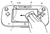
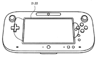
図1に示す情報処理装置10には、表示装置(例えば、液晶ディスプレイ)が設けられており、当該表示装置の画面上にはタッチパネル11が設けられている。タッチパネル11の表面に保護シートを貼り付けるために、図2に示す保護シート積層体20が用いられる。
保護シート積層体20は、大まかに言うと、図3に示すように、3つのシート(補助シート21、保護シート22、剥離シート23)を積層した構造となっている。
保護シート22は、タッチパネル11の表面を傷等から保護するために当該タッチパネル11の表面に貼り付けられる透明のシート(またはフィルム)である。保護シート22の大きさは、タッチパネル11の表面(露出部分)の大きさよりも若干小さい。
補助シート21は、保護シート22の表側面(保護シート22がタッチパネル11に貼り付けられた後に露出する側の面)に貼り付けられており、保護シート22の貼り付け作業を容易にするために設けられている。本実施形態では、補助シート21として透明なシート(またはフィルム)を用いるが、補助シート21は透明である必要はない。
補助シート21は、保護シート22に対応する大きさの矩形の矩形部24と、2つの掴み部(第1掴み部25、第2掴み部26)とで構成される。矩形部24と第1掴み部25の間の境界線である第1折り曲げ線27には、当該第1折り曲げ線27において補助シート21を容易に折り曲げられるようにするための折り曲げ加工が施されている。矩形部24と第2掴み部26の間の境界線である第2折り曲げ線28についても同様に、折り曲げ加工が施されている。折り曲げ加工の典型例として、ミシン目や、V字型の溝が挙げられる。第1掴み部25には、穴29が設けられている。矩形部24の大きさは、タッチパネル11の表面(露出部分)の大きさと同一か、または若干小さいのが好ましい。
剥離シート23は、保護シート22の裏側面に貼り付けられており、保護シート22の貼り付け作業を開始するまでの間、保護シート22の裏側面に異物が付着するのを防止するために設けられている。
剥離シート23は、保護シート22のほぼ中央を横切るような分離線34を境界として、2つの剥離部(第1剥離部30、第2剥離部31)に分かれており、第1剥離部30および第2剥離部31には、それぞれ、第1ラベル32および第2ラベル33が貼り付けられている。第1ラベル32および第2ラベル33は、ユーザが第1剥離部30および第2剥離部31を剥がす際に、分離線34に近い部分から剥がし始めるようにユーザを誘導する役割を有する。第1ラベル32および第2ラベル33は、例えば、紙製のシール等であってもよい。
次に、図4~図10を参照して、保護シート積層体20を用いた保護シート22の貼り付け方法を説明する。
まず、図4に示すように、第1折り曲げ線27および第2折り曲げ線28において補助シート21を折り曲げて、第1掴み部25および第2掴み部26が表側(すなわち、補助シート21から見て保護シートとは反対方向)に延びるようにする。このとき、第1折り曲げ線27および第2折り曲げ線28において補助シート21をほぼ直角に折り曲げるのが好ましい。
次に、図5に示すように、第1ラベル32を掴んで、保護シート積層体20から第1剥離部30を剥がす。このように、第1ラベル32を掴んで第1剥離部30を剥がすことによって、第1剥離部30は、前述した分離線34(図3)に近い部分から剥がれることになる。分離線34は保護シート22を横切るような位置にあるため、分離線34に近い部分から第1剥離部30を剥がせば、第1剥離部30と一緒に保護シート22まで剥がれてしまうことがない。
次に、図6に示すように、第2ラベル33を掴んで、保護シート積層体20から第2剥離部31を剥がす。この場合も、分離線34に近い部分から第2剥離部31を剥がすことになるので、第2剥離部31と一緒に保護シート22まで剥がれてしまうことがない。なお、第2剥離部31を剥がす際に、一方の手(例えば左手)で第2ラベル33を掴むとともに、他方の手(例えば右手)で第1掴み部25を掴むことによって、保護シート22に一切触れることなく第2剥離部31を剥がすことができる。よって、保護シート22の裏側面に指紋が付着するのを防ぐことができる。また、第1掴み部25には穴29が設けられているため、第2剥離部31を剥がしている途中や剥がした後に、第1掴み部25を掴んでいる手が滑って保護シート積層体20を落としてしまうことがない。よって、落下によって保護シート22の裏側面に汚れが付着するのを防ぐことができる。
次に、図7に示すように、一方の手(例えば右手)で第1掴み部25を掴み、他方の手(例えば左手)で第2掴み部26を掴んだ状態で、矩形部24における第1掴み部25が設けられている辺(以下、便宜上、右辺と称す)を、タッチパネル11の右辺に合わせるようにして、矩形部24の右辺に近い保護シート22の裏側面の一部をタッチパネル11の表面に当接させる。このとき、第1掴み部25は、矩形部24の角(右上角および右下角)から離れた位置に設けられているため、ユーザにとって、矩形部24の角の位置(実質的に、保護シート22の角の位置に相当)を容易にかつ正確に把握することができる。よって、ユーザにとって、矩形部24の位置決め(その結果として、保護シート22の位置決め)が容易となる。また、第1掴み部25には穴29が設けられているため、第1掴み部25を掴んでいる手が滑ることがなく、正確に位置決めをすることができる。
次に、図8に示すように、一方の手(例えば左手)で第2掴み部26を掴みながら、他方の手(例えば右手)で、第1掴み部25側から第2掴み部26側に向かって矩形部24の表面を滑らせるようにして、保護シート22の裏側面をタッチパネル11の表面に徐々に貼り付けていく。なお、後述するように、保護シート22の裏側面は接着剤で覆われているが、その粘着力は、容易に貼り直しが出来る程度に抑えられている。よって、この段階では、ユーザは、第2掴み部26を引き上げるだけで容易に保護シート22をタッチパネル11から剥がすことができ、再度図7の状態から保護シート22を貼り直すことができる。
図9に示すように保護シート22の裏側面全体がタッチパネル11に貼り付けられた後、図10に示すように、第2掴み部26を捻るようにして、矩形部24の角(図10の例では左下角)の部分を保護シート22から剥がし、さらに、第2掴み部26を引き上げることによって、保護シート22から補助シート21を完全に剥がす。このように、矩形部24の角の部分から補助シート21を剥がすことによって、補助シート21と一緒に保護シート22がタッチパネル11から剥がれてしまうのを防ぐことができる。また、第2掴み部26は、矩形部24の角の近くにまで延びているので、第2掴み部26を捻るようにすることによって、容易に矩形部24の角の部分から補助シート21を剥がすことができる。
こうして、最終的にタッチパネル11の表面に保護シート22だけが残り、タッチパネル11への保護シート22の貼り付けが完了する。
次に、保護シート積層体20を用いることによって得られるさらなる効果について説明する。
保護シート積層体20は、図11に示すように、被保護面(タッチパネルやディスプレイ等)の周囲にハウジングや枠部材等による段差を有するような電子機器に対して、特に有効である。
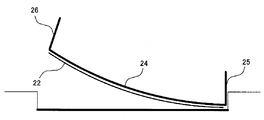
すでに説明したように、保護シート積層体20には第1掴み部25および第2掴み部26が設けられており、これらの掴み部は、表側(すなわち、補助シート21から見て、保護シート22とは反対方向)に向かって延びている。したがって、図11に示すような段差がある場合においても、ユーザは、図12のように被保護面に保護シート22を貼り付け始めるときから、図13のように被保護面に保護シート22の裏側面全体を貼り付け終わるまでの間、補助シート21が邪魔になることがない。よって、被保護面と保護シート22の間への気泡の混入が抑えられ、保護シート22を適切に貼り付けることができる。
また、保護シート積層体20は、図14に示すように、被保護面の周囲にハウジングや枠部材等による隙間を有するような電子機器に対しても、特に有効である。
保護シート積層体20は、図15に示すように、保護シート22の端部が、矩形部24と第1掴み部25との間の境界線(すなわち、第1折り曲げ線27)よりも若干内側に位置するように構成されている。したがって、図16に示すように、保護シート22の裏側面の一部を被保護面に当接させるときに、保護シート22の端部が隙間に近づき過ぎることがない。よって、保護シート22の端部が隙間に挟まってしまうことを防止することができる。特に、被保護面が抵抗膜方式のタッチパネルである場合には、保護シート22の端部が隙間に挟まってしまうと誤動作の原因となるため、それを防止することが重要である。
次に、図17を参照して、保護シート積層体20の構造についてより詳細に説明する。
前述したように、保護シート積層体20は、大まかに言うと、3つのシート(補助シート21、保護シート22、剥離シート23)を積層した構造となっているが、より詳しく説明すると、補助シート21と保護シート22は、弱粘着シート41を介して貼り付けられている。弱粘着シート41は、両面とも弱い粘着力(または吸着力)を有するようなシートである。
補助シート21の裏側面全体は、強い粘着力を有する接着剤40で覆われている。そして、補助シート21の矩形部24には、接着剤40を介して弱粘着シート41が貼り付けられており、補助シート21の掴み部(第1掴み部25、第2掴み部26)には、接着剤40を介してカバーシート42が貼り付けられている。カバーシート42は、ユーザが掴み部を掴む時に、接着剤40がユーザの手に触れないようにするために設けられている。
保護シート22の裏側面は、接着剤43で覆われている。そして、保護シート22の裏側面には、接着剤43を介して剥離シート23(第1剥離部30、第2剥離部31)が貼り付けられている。接着剤43の粘着力は、弱粘着シート41の粘着力(または吸着力)よりも強く、かつ、接着剤40の粘着力よりも小さい。
特に、弱粘着シート41の粘着力(または吸着力)と、接着剤43の粘着力は、保護シート22の貼り付け作業の途中では容易に貼り直しができ、なおかつ、保護シート22の裏側面全体が被保護面に貼り付けられた後は、補助シート21(および弱粘着シート41)と一緒に保護シート22が剥がれてしまうことがないように調整されている。
なお、上記実施形態は単なる一例に過ぎず、種々の変形例が考えられることは言うまでもない。
例えば、上記実施形態では、補助シート21を折り曲げることによって、表側(すなわち、補助シート21から見て保護シートとは反対方向)に向かって延びる掴み部(第1掴み部25および第2掴み部26)を形成しているが、他の実施形態では、図18に示すように、掴み部(第1掴み部25および第2掴み部26)となる部材を、接着剤等で補助シート21に取り付けるようにしてもよい。
また、上記実施形態では、2つの掴み部(第1掴み部25および第2掴み部26)を設けているが、他の実施形態では、1つの掴み部(例えば、第1掴み部25または第2掴み部26のいずれか一方)だけを設けてもよい。または、3つ以上の掴み部を設けてもよい。
また、上記実施形態では、矩形部24の辺上に掴み部を設けているが、他の実施形態では、矩形部24の辺から離れた位置に掴み部を設けてもよい。
また、上記実施形態では、保護シート22および矩形部24が矩形であるが、被保護面が矩形以外の形状であれば、当然ながら、保護シート22および矩形部24の形状も、被保護面の形状に応じた形状となるべきである。
また、上記実施形態では、保護シート22の表側面に、弱粘着シート41を介して補助シート21が貼り付けられているが、他の実施形態では、弱粘着シート41を介さずに、保護シート22の表側面に補助シート21が貼り付けられていてもよい。
また、上記実施形態では、第1掴み部25から第2掴み部26に向かって保護シート22をタッチパネル11に貼り付けているが、他の実施形態では、第2掴み部26から第1掴み部25に向かって保護シート22をタッチパネル11に貼り付けてもよい。
また、上記実施形態では、第1掴み部25および第2掴み部26が矩形部24の左右の辺にそれぞれ設けられているが、他の実施形態では、第1掴み部25および第2掴み部26が矩形部24の上下の辺にそれぞれ設けられていてもよい。
10 情報処理装置
11 タッチパネル
20 保護シート積層体
21 補助シート
22 保護シート
23 剥離シート
24 矩形部
25 第1掴み部
26 第2掴み部
27 第1折り曲げ線
28 第2折り曲げ線
29 穴
30 第1剥離部
31 第2剥離部
32 第1ラベル
33 第2ラベル
34 分離線
40 接着剤
41 弱粘着シート
42 カバーシート
43 接着剤
11 タッチパネル
20 保護シート積層体
21 補助シート
22 保護シート
23 剥離シート
24 矩形部
25 第1掴み部
26 第2掴み部
27 第1折り曲げ線
28 第2折り曲げ線
29 穴
30 第1剥離部
31 第2剥離部
32 第1ラベル
33 第2ラベル
34 分離線
40 接着剤
41 弱粘着シート
42 カバーシート
43 接着剤
Claims (16)
- 電子機器の被保護面に保護シートを貼り付けるための保護シート積層体であって、
前記保護シートと、
前記保護シートの表側面を覆うように当該保護シートに貼り付けられた補助シートと、
前記補助シートから前記保護シートとは反対方向に延びる少なくとも1つの掴み部とを備えた、保護シート積層体。 - 前記補助シートには、所定の折り曲げ線において容易に折り曲げられるようにするための折り曲げ加工が施されており、
前記折り曲げ線において当該補助シートを折り曲げることによって、当該補助シートの一部が前記掴み部として機能するように構成されている、請求項1に記載の保護シート積層体。 - 前記保護シートは矩形であり、
前記補助シートは、前記保護シートに対応する大きさの矩形の矩形部を有し、
前記掴み部は、前記矩形部の辺上で、かつ、当該辺の両端の角から離れた位置に設けられている、請求項1または請求項2に記載の保護シート積層体。 - 前記保護シートは矩形であり、
前記補助シートは、前記保護シートに対応する大きさの矩形の矩形部を有し、
前記矩形部の第1辺上と、当該第1辺に対向する第2辺上には、第1掴み部および第2掴み部がそれぞれ設けられており、
前記第1辺と前記第1掴み部の境界部分の長さが、前記第2辺と前記第2掴み部の境界部分の長さよりも短い、請求項1または請求項2に記載の保護シート積層体。 - 前記掴み部には穴が設けられている、請求項1または請求項2に記載の保護シート積層体。
- 前記補助シートの前記折り曲げ線は、前記保護シートから僅かに離れた位置に設けられている、請求項2に記載の保護シート積層体。
- 前記保護シートの裏側面を覆うように当該保護シートに貼り付けられた剥離シートをさらに備え、
前記剥離シートには、前記保護シートを横切る分離線において当該剥離シートを少なくとも2つに分離可能に構成されている、請求項1または請求項2に記載の保護シート積層体。 - 前記保護シートの裏側面を覆うように当該保護シートに貼り付けられた剥離シートをさらに備え、
前記剥離シートの外縁は、全周にわたって、前記保護シートおよび前記補助シートの外縁よりも外側である、請求項1または請求項2に記載の保護シート積層体。 - 前記保護シートは矩形であり、
前記掴み部を除いた前記補助シートの外縁は、全周にわたって、前記被保護面の外縁よりも内側である、請求項1または請求項2に記載の保護シート積層体。 - 前記保護シートと前記補助シートの間の粘着力は、前記保護シートと前記被保護面の間の粘着力よりも小さくなるように調整されている、請求項1または請求項2に記載の保護シート積層体。
- 前記保護シートと前記補助シートは、弱粘着シートを介して貼り付けられており、
前記保護シートと前記被保護面の間の粘着力は、前記補助シートと前記弱粘着シートの間の粘着力よりも小さく、かつ、前記保護シートと前記弱粘着シートの間の粘着力よりも大きくなるように調整されている、請求項1または請求項2に記載の保護シート積層体。 - 請求項1に記載の保護シート積層体を用いて電子機器の被保護面に保護シートを貼り付ける保護シート貼り付け方法であって、
前記掴み部を掴んで、前記保護シートの裏側面の少なくとも一部を前記被保護面に当接させる工程と、
前記保護シートの裏側面全体が前記被保護面に貼り付くように、前記保護シート積層体を前記被保護面に貼り付ける工程と、
前記保護シート積層体から前記補助シートを剥がす工程とを備えた、保護シート貼り付け方法。 - 請求項1に記載の保護シート積層体を用いて電子機器の被保護面に保護シートを貼り付ける保護シート貼り付け方法であって、
前記保護シートの裏側面の少なくとも一部を前記被保護面に当接させる工程と、
前記保護シートの裏側面全体が前記被保護面に貼り付くように、前記保護シート積層体を前記被保護面に貼り付ける工程と、
前記掴み部を掴んで、前記保護シート積層体から前記補助シートを剥がす工程とを備えた、保護シート貼り付け方法。 - 請求項2に記載の保護シート積層体を用いて電子機器の被保護面に保護シートを貼り付ける保護シート貼り付け方法であって、
前記補助シートを前記折り曲げ線において折り曲げることによって、当該補助シートの一部を前記掴み部として機能させる工程と、
前記掴み部を掴んで、前記保護シートの裏側面の少なくとも一部を前記被保護面に当接させる工程と、
前記保護シートの裏側面全体が前記被保護面に貼り付くように、前記保護シート積層体を前記被保護面に貼り付ける工程と、
前記保護シート積層体から前記補助シートを剥がす工程とを備えた、保護シート貼り付け方法。 - 請求項3に記載の保護シート積層体を用いて電子機器の被保護面に保護シートを貼り付ける保護シート貼り付け方法であって、
前記掴み部を掴んで、前記矩形部における前記掴み部が設けられている第1辺の両端の角部を、前記被保護面の角部に位置合わせする工程と、
前記矩形部の前記第1辺に近い前記保護シートの裏側面の一部を前記被保護面に当接させる当接工程と、
前記保護シートの裏側面全体が前記被保護面に貼り付くように、前記保護シート積層体を前記被保護面に貼り付ける工程と、
前記保護シート積層体から前記補助シートを剥がす工程とを備えた、保護シート貼り付け方法。 - 請求項4に記載の保護シート積層体を用いて電子機器の被保護面に保護シートを貼り付ける保護シート貼り付け方法であって、
前記第1掴み部および前記第2掴み部を掴んで、前記矩形部の前記第1辺に近い前記保護シートの裏側面の一部を前記被保護面に当接させる工程と、
少なくとも前記第2掴み部を掴んだままで、最終的に前記保護シートの裏側面全体が前記被保護面に貼り付くように、前記第1辺から前記第2辺に向かって前記保護シート積層体を前記被保護面に貼り付ける工程と、
前記第2掴み部を捻ることによって、前記保護シートから前記補助シートの一部を剥がす工程と、
前記第2掴み部を掴んで、前記保護シート積層体から前記補助シート全体を剥がす工程とを備えた、保護シート貼り付け方法。
Priority Applications (1)
| Application Number | Priority Date | Filing Date | Title |
|---|---|---|---|
| PCT/JP2012/075018 WO2014049813A1 (ja) | 2012-09-28 | 2012-09-28 | 保護シート積層体および保護シート貼り付け方法 |
Applications Claiming Priority (1)
| Application Number | Priority Date | Filing Date | Title |
|---|---|---|---|
| PCT/JP2012/075018 WO2014049813A1 (ja) | 2012-09-28 | 2012-09-28 | 保護シート積層体および保護シート貼り付け方法 |
Publications (1)
| Publication Number | Publication Date |
|---|---|
| WO2014049813A1 true WO2014049813A1 (ja) | 2014-04-03 |
Family
ID=50387276
Family Applications (1)
| Application Number | Title | Priority Date | Filing Date |
|---|---|---|---|
| PCT/JP2012/075018 Ceased WO2014049813A1 (ja) | 2012-09-28 | 2012-09-28 | 保護シート積層体および保護シート貼り付け方法 |
Country Status (1)
| Country | Link |
|---|---|
| WO (1) | WO2014049813A1 (ja) |
Cited By (4)
| Publication number | Priority date | Publication date | Assignee | Title |
|---|---|---|---|---|
| WO2016035196A1 (ja) * | 2014-09-04 | 2016-03-10 | トリニティ株式会社 | 保護シート |
| JP2016055439A (ja) * | 2014-09-05 | 2016-04-21 | 横浜ゴム株式会社 | 空気入りタイヤの製造方法 |
| JP2016112735A (ja) * | 2014-12-12 | 2016-06-23 | 土屋工業株式会社 | 表面貼付シートの製造方法 |
| JP2017130907A (ja) * | 2016-01-21 | 2017-07-27 | エレコム株式会社 | 保護フィルム貼着用器具及びこれを利用した保護フィルムの貼着方法 |
Citations (6)
| Publication number | Priority date | Publication date | Assignee | Title |
|---|---|---|---|---|
| JPH04299305A (ja) * | 1991-03-28 | 1992-10-22 | Mitsubishi Electric Corp | ディスプレイモニタの前面フィルタ取付構造 |
| JP2006145918A (ja) * | 2004-11-19 | 2006-06-08 | Nintendo Co Ltd | 保護シートの装着構造体 |
| JP2006155452A (ja) * | 2004-12-01 | 2006-06-15 | Nissha Printing Co Ltd | タッチパネル用保護フィルム積層体 |
| JP2008281608A (ja) * | 2007-05-08 | 2008-11-20 | Funai Electric Co Ltd | 液晶表示面保護シートの取付構造 |
| JP2012067219A (ja) * | 2010-09-24 | 2012-04-05 | Hori Co Ltd | シート貼付構造体 |
| JP4964347B1 (ja) * | 2011-08-12 | 2012-06-27 | 株式会社ソニー・コンピュータエンタテインメント | 保護フィルムを含むフィルム積層体 |
-
2012
- 2012-09-28 WO PCT/JP2012/075018 patent/WO2014049813A1/ja not_active Ceased
Patent Citations (6)
| Publication number | Priority date | Publication date | Assignee | Title |
|---|---|---|---|---|
| JPH04299305A (ja) * | 1991-03-28 | 1992-10-22 | Mitsubishi Electric Corp | ディスプレイモニタの前面フィルタ取付構造 |
| JP2006145918A (ja) * | 2004-11-19 | 2006-06-08 | Nintendo Co Ltd | 保護シートの装着構造体 |
| JP2006155452A (ja) * | 2004-12-01 | 2006-06-15 | Nissha Printing Co Ltd | タッチパネル用保護フィルム積層体 |
| JP2008281608A (ja) * | 2007-05-08 | 2008-11-20 | Funai Electric Co Ltd | 液晶表示面保護シートの取付構造 |
| JP2012067219A (ja) * | 2010-09-24 | 2012-04-05 | Hori Co Ltd | シート貼付構造体 |
| JP4964347B1 (ja) * | 2011-08-12 | 2012-06-27 | 株式会社ソニー・コンピュータエンタテインメント | 保護フィルムを含むフィルム積層体 |
Cited By (7)
| Publication number | Priority date | Publication date | Assignee | Title |
|---|---|---|---|---|
| WO2016035196A1 (ja) * | 2014-09-04 | 2016-03-10 | トリニティ株式会社 | 保護シート |
| JPWO2016035196A1 (ja) * | 2014-09-04 | 2017-07-27 | トリニティ株式会社 | 保護シート |
| JP2016055439A (ja) * | 2014-09-05 | 2016-04-21 | 横浜ゴム株式会社 | 空気入りタイヤの製造方法 |
| JP2016112735A (ja) * | 2014-12-12 | 2016-06-23 | 土屋工業株式会社 | 表面貼付シートの製造方法 |
| JP2017130907A (ja) * | 2016-01-21 | 2017-07-27 | エレコム株式会社 | 保護フィルム貼着用器具及びこれを利用した保護フィルムの貼着方法 |
| CN106985487A (zh) * | 2016-01-21 | 2017-07-28 | 股份公司卡拉永国际 | 保护膜附接装置 |
| CN106985487B (zh) * | 2016-01-21 | 2019-12-10 | 股份公司卡拉永国际 | 保护膜附接装置 |
Similar Documents
| Publication | Publication Date | Title |
|---|---|---|
| JP6048460B2 (ja) | 保護フィルム複合体及び保護フィルムの貼付方法 | |
| JP4887451B1 (ja) | シート貼付構造体 | |
| KR101176316B1 (ko) | 스마트폰 및 태블릿 피시의 액정에 액정보호필름을 용이하게 부착할 수 있는 이형필름과 어플리케이션 점착라벨 | |
| JP2006145918A (ja) | 保護シートの装着構造体 | |
| JP3200045U (ja) | 保護フィルム複合体 | |
| KR20120071195A (ko) | 보호필름유닛 및 이를 사용한 패널의 조립방법 | |
| KR20180100728A (ko) | 보호필름 구조체 및 보호필름 부착보조 구조체 | |
| KR101495075B1 (ko) | 기능성 필름을 갖는 액정보호필름 구조체 | |
| KR200469016Y1 (ko) | 표면보호필름 부착가이드 | |
| WO2019181349A1 (ja) | 皮膚貼付用シート | |
| JP2006509903A (ja) | マスター加工作業を行うデバイスおよび方法 | |
| JP3164602U (ja) | シート貼付構造体 | |
| JP3169203U (ja) | 保護シート保持物 | |
| JP6486949B2 (ja) | 保護シート | |
| TW201336689A (zh) | 保護膜及其製造方法 | |
| JP2013256763A (ja) | 仕上げ床材および仕上げ床材の設置方法 | |
| JP6374223B2 (ja) | 保護部材 | |
| JP6236718B2 (ja) | 転写用の複合層構造 | |
| WO2023054670A1 (ja) | 医療用ドレッシング材 | |
| JP2012170480A (ja) | 貼り薬の貼付補助器 | |
| US7875332B2 (en) | Adhesive tape and method of use | |
| KR20140002324A (ko) | 휴대폰 보호필름 구조체 | |
| JP5928857B1 (ja) | 保護シート材における保護フィルムの貼付方法 | |
| CN205648187U (zh) | 显示装置及其保护片结构 | |
| JP2001271042A (ja) | 粘着保護シート |
Legal Events
| Date | Code | Title | Description |
|---|---|---|---|
| 121 | Ep: the epo has been informed by wipo that ep was designated in this application |
Ref document number: 12885377 Country of ref document: EP Kind code of ref document: A1 |
|
| NENP | Non-entry into the national phase |
Ref country code: DE |
|
| 122 | Ep: pct application non-entry in european phase |
Ref document number: 12885377 Country of ref document: EP Kind code of ref document: A1 |
|
| NENP | Non-entry into the national phase |
Ref country code: JP |