WO2014045997A1 - 第二種吸収式ヒートポンプ - Google Patents
第二種吸収式ヒートポンプ Download PDFInfo
- Publication number
- WO2014045997A1 WO2014045997A1 PCT/JP2013/074660 JP2013074660W WO2014045997A1 WO 2014045997 A1 WO2014045997 A1 WO 2014045997A1 JP 2013074660 W JP2013074660 W JP 2013074660W WO 2014045997 A1 WO2014045997 A1 WO 2014045997A1
- Authority
- WO
- WIPO (PCT)
- Prior art keywords
- condenser
- absorber
- refrigerant
- heat pump
- supply path
- Prior art date
- Legal status (The legal status is an assumption and is not a legal conclusion. Google has not performed a legal analysis and makes no representation as to the accuracy of the status listed.)
- Ceased
Links
Images

Classifications
-
- F—MECHANICAL ENGINEERING; LIGHTING; HEATING; WEAPONS; BLASTING
- F25—REFRIGERATION OR COOLING; COMBINED HEATING AND REFRIGERATION SYSTEMS; HEAT PUMP SYSTEMS; MANUFACTURE OR STORAGE OF ICE; LIQUEFACTION SOLIDIFICATION OF GASES
- F25B—REFRIGERATION MACHINES, PLANTS OR SYSTEMS; COMBINED HEATING AND REFRIGERATION SYSTEMS; HEAT PUMP SYSTEMS
- F25B15/00—Sorption machines, plants or systems, operating continuously, e.g. absorption type
- F25B15/02—Sorption machines, plants or systems, operating continuously, e.g. absorption type without inert gas
-
- F—MECHANICAL ENGINEERING; LIGHTING; HEATING; WEAPONS; BLASTING
- F25—REFRIGERATION OR COOLING; COMBINED HEATING AND REFRIGERATION SYSTEMS; HEAT PUMP SYSTEMS; MANUFACTURE OR STORAGE OF ICE; LIQUEFACTION SOLIDIFICATION OF GASES
- F25B—REFRIGERATION MACHINES, PLANTS OR SYSTEMS; COMBINED HEATING AND REFRIGERATION SYSTEMS; HEAT PUMP SYSTEMS
- F25B30/00—Heat pumps
- F25B30/04—Heat pumps of the sorption type
-
- F—MECHANICAL ENGINEERING; LIGHTING; HEATING; WEAPONS; BLASTING
- F25—REFRIGERATION OR COOLING; COMBINED HEATING AND REFRIGERATION SYSTEMS; HEAT PUMP SYSTEMS; MANUFACTURE OR STORAGE OF ICE; LIQUEFACTION SOLIDIFICATION OF GASES
- F25B—REFRIGERATION MACHINES, PLANTS OR SYSTEMS; COMBINED HEATING AND REFRIGERATION SYSTEMS; HEAT PUMP SYSTEMS
- F25B43/00—Arrangements for separating or purifying gases or liquids; Arrangements for vaporising the residuum of liquid refrigerant, e.g. by heat
- F25B43/04—Arrangements for separating or purifying gases or liquids; Arrangements for vaporising the residuum of liquid refrigerant, e.g. by heat for withdrawing non-condensible gases
- F25B43/046—Arrangements for separating or purifying gases or liquids; Arrangements for vaporising the residuum of liquid refrigerant, e.g. by heat for withdrawing non-condensible gases for sorption type systems
-
- Y—GENERAL TAGGING OF NEW TECHNOLOGICAL DEVELOPMENTS; GENERAL TAGGING OF CROSS-SECTIONAL TECHNOLOGIES SPANNING OVER SEVERAL SECTIONS OF THE IPC; TECHNICAL SUBJECTS COVERED BY FORMER USPC CROSS-REFERENCE ART COLLECTIONS [XRACs] AND DIGESTS
- Y02—TECHNOLOGIES OR APPLICATIONS FOR MITIGATION OR ADAPTATION AGAINST CLIMATE CHANGE
- Y02A—TECHNOLOGIES FOR ADAPTATION TO CLIMATE CHANGE
- Y02A30/00—Adapting or protecting infrastructure or their operation
- Y02A30/27—Relating to heating, ventilation or air conditioning [HVAC] technologies
-
- Y—GENERAL TAGGING OF NEW TECHNOLOGICAL DEVELOPMENTS; GENERAL TAGGING OF CROSS-SECTIONAL TECHNOLOGIES SPANNING OVER SEVERAL SECTIONS OF THE IPC; TECHNICAL SUBJECTS COVERED BY FORMER USPC CROSS-REFERENCE ART COLLECTIONS [XRACs] AND DIGESTS
- Y02—TECHNOLOGIES OR APPLICATIONS FOR MITIGATION OR ADAPTATION AGAINST CLIMATE CHANGE
- Y02B—CLIMATE CHANGE MITIGATION TECHNOLOGIES RELATED TO BUILDINGS, e.g. HOUSING, HOUSE APPLIANCES OR RELATED END-USER APPLICATIONS
- Y02B30/00—Energy efficient heating, ventilation or air conditioning [HVAC]
- Y02B30/52—Heat recovery pumps, i.e. heat pump based systems or units able to transfer the thermal energy from one area of the premises or part of the facilities to a different one, improving the overall efficiency
-
- Y—GENERAL TAGGING OF NEW TECHNOLOGICAL DEVELOPMENTS; GENERAL TAGGING OF CROSS-SECTIONAL TECHNOLOGIES SPANNING OVER SEVERAL SECTIONS OF THE IPC; TECHNICAL SUBJECTS COVERED BY FORMER USPC CROSS-REFERENCE ART COLLECTIONS [XRACs] AND DIGESTS
- Y02—TECHNOLOGIES OR APPLICATIONS FOR MITIGATION OR ADAPTATION AGAINST CLIMATE CHANGE
- Y02B—CLIMATE CHANGE MITIGATION TECHNOLOGIES RELATED TO BUILDINGS, e.g. HOUSING, HOUSE APPLIANCES OR RELATED END-USER APPLICATIONS
- Y02B30/00—Energy efficient heating, ventilation or air conditioning [HVAC]
- Y02B30/62—Absorption based systems
Definitions
- the present invention relates to a second type absorption heat pump having a non-condensable gas exhaust function.
- the second type absorption heat pump generates refrigerant vapor by heating a refrigerant liquid with a heating medium in an evaporator, and the generated refrigerant vapor is absorbed by an absorbing solution in the absorber and is generated at this time.
- the heated medium is heated by the absorbed heat.
- the regenerator the absorbing solution having a low solute concentration is heated by a heating medium, thereby generating refrigerant vapor and generating an absorbing solution having a high solute concentration.
- the refrigerant vapor generated in the regenerator is cooled by a cooling medium so as to be condensed and liquefied to generate a refrigerant liquid.
- Such a second type absorption heat pump has a vacuum inside, but the air enters from the pipe connection part, or the steel material constituting the heat pump and the absorbing solution react to generate hydrogen gas. .
- Such non-condensable gas significantly reduces the capacity of the heat pump and must be exhausted.
- a refrigerant supply path for the refrigerant liquid from the condenser to the evaporator is branched, and an ejector and an extraction tank are provided in the branch path, so The condensed gas has been collected in an extraction tank via an ejector and exhausted (for example, refer to Patent Document 1).
- the non-condensed gas in the condenser is extracted by causing the ejector to act by flowing the refrigerant liquid through the branch path branched from the refrigerant supply path.
- a refrigerant liquid accumulates in the extraction tank together with the gas. Therefore, the extraction tank must be provided with a path for returning the refrigerant liquid from the extraction tank to the condenser, which complicates the path.
- a part of the refrigerant liquid flowing through the refrigerant supply path is branched into the branch path to operate the ejector, a sufficient flow of the refrigerant liquid must be ensured.
- the present invention has been made in view of such circumstances, and an object of the present invention is to provide a second type absorption heat pump that can efficiently extract non-condensable gas with a simple configuration.
- a second type absorption heat pump for solving the above-described problems is an evaporator that heats a refrigerant liquid and generates refrigerant vapor, and an absorption solution that absorbs the refrigerant vapor generated in the evaporator.
- An absorber that heats the medium to be heated with absorption heat, and an absorption dilute solution whose solute concentration is reduced by absorbing the refrigerant vapor in the absorber is introduced and heated to generate refrigerant vapor, and at the same time, the solute
- a second type absorption heat pump comprising: a regenerator that generates a high concentration absorbing solution; and a condenser that cools the refrigerant vapor generated in the regenerator and generates a refrigerant liquid.
- an absorber bleed tank is provided in the front stage of the absorber, and an ejector is provided in the front stage of the absorber bleed tank.
- a condenser bleed tank is provided at the subsequent stage of the condenser.
- An exhaust path for exhausting non-condensable gas collected in the absorber bleed tank and the condenser bleed tank from one vacuum pump may be provided.
- the second type absorption heat pump may be arranged such that the absorber bleed tank and the ejector are located above the connection port of the bleed path connected to the absorber.
- the second type absorption heat pump may be configured such that a refrigerant supply path from the condenser is connected to a connection port provided on the upper surface or upper side surface of the condenser bleed tank.
- the refrigerant supply path connecting the condenser bleed tank and the condenser may be parallel or descending in the whole area from the condenser to the condenser bleed tank.
- an ejector is provided in the absorbent solution supply path from the regenerator to the absorber without providing a dedicated path for extracting the non-condensable gas, and the flow of the absorbent solution passing through the ejector is utilized.
- the non-condensable gas in the absorber can be extracted into the absorbing solution supply path via the extraction path and collected in the absorber extraction tank.
- FIG. 1 It is a refrigerant circuit figure showing the outline of the whole composition of the 2nd kind absorption heat pump concerning the present invention.
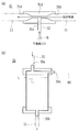
- A is sectional drawing which shows the outline of a structure of the ejector in the 2nd type absorption heat pump which concerns on this invention
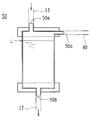
- (b) is sectional drawing which shows the outline of a structure of an absorber bleed tank. It is sectional drawing which shows the outline of a structure of the condenser bleed tank in the 2nd type absorption heat pump which concerns on this invention.
- FIG. 1 is a refrigerant circuit diagram showing an outline of the overall configuration of a second type absorption heat pump 1 according to the present invention.
- the second type absorption heat pump 1 includes an evaporator 2, an absorber 3, a regenerator 4, and a condenser 5, and the total amount of the absorbing solution S from the regenerator 4 to the absorber 3.
- an absorber bleed tank 30 is provided in the front stage of the absorber 3
- an ejector 31 is provided in the front stage of the absorber bleed tank 30.
- the non-condensable gas N in the absorber 3 is extracted through the extraction path 12 to the absorption solution supply path 11 by the flow of the absorption solution S passing through the ejector 31, and the absorber extraction tank 30. Has been made to be collected.
- the evaporator 2 is configured to generate a refrigerant vapor Rg by heating the refrigerant liquid R.
- the evaporator 2 and the condenser 5 are connected by a refrigerant supply path 13.
- the refrigerant supply path 13 passes through the condenser bleed tank 50, the refrigerant pump 13p, and the expansion valve 13v in order from the condenser 5 to the evaporator 2, and the condenser bleed tank 50, the refrigerant pump 13p, and the expansion valve. 13v is connected.
- the evaporator 2 and the absorber 3 are connected by a refrigerant vapor supply path 14.
- a receiver 6 is connected between the evaporator 2 and the absorber 3.
- the refrigerant liquid R supplied to the evaporator 2 from the condenser 5 via the refrigerant supply path 13 is heated by the evaporator 2 to become the refrigerant vapor Rg, and then the receiver 6 is connected from the refrigerant vapor supply path 14. Then, it is supplied to the absorber 3.
- the absorber 3 is configured such that the absorbing solution S supplied from the regenerator 4 absorbs the refrigerant vapor Rg supplied from the refrigerant vapor supply path 14 and generates absorption heat.
- the absorber 3 is configured to heat the medium to be heated T flowing in the heat exchanger 32 provided in the absorber 3 and obtain a heat output by the absorbed heat.
- the upper part of the absorber 3 and the bottom part of the regenerator 4 are connected by an absorbing solution supply path 11.
- a solution pump 11 p, a solution heat exchanger 7, an expansion valve 11 v, an ejector 31, and an absorber bleed tank 30 are connected in order from the regenerator 4 to the absorber 3.
- the bottom of the absorber 3 and the top of the regenerator 4 are connected by an absorption dilute solution recovery path 15 via an expansion valve 15v.
- the absorption solution supply path 11 and the absorption dilute solution recovery path 15 are configured to exchange heat with each other by the solution heat exchanger 7.
- an extraction path 12 connected to the ejector 31 is provided at a position P on the side wall surface higher than the liquid pool 3 a in the absorber 3.
- the refrigerant vapor Rg supplied from the upper part of the absorber 3 via the refrigerant vapor supply path 14 is similarly absorbed by the absorption solution S supplied from the upper part of the absorber 3 via the absorbent solution supply path 11.
- the heat exchanger 32 of the medium to be heated T is heated by the absorbed heat.
- the diluted absorption solution Sd having a low solute concentration due to absorption of the refrigerant vapor Rg is recovered from the bottom of the absorber 3 to the regenerator 4 via the absorption diluted solution recovery path 15.
- the solution heat exchanger 7 Heat is exchanged between the absorbing diluted solution recovery path 15 through which the absorbing diluted solution Sd having unrecovered heat flows and the absorbing solution supply path 11 through which the absorbing solution S from the regenerator 4 flows and is supplied to the absorber 3. The temperature of the absorption solution S is increased.
- the absorber bleed tank 30 and the ejector 31 are arranged at a position higher than the position P where the bleed passage 12 is connected.
- the ejector 31 connects the absorbing solution supply path 11 through which the entire amount of the absorbing solution S from the regenerator 4 to the absorber 3 flows to the opposing connection ports 31a and 31b, respectively.
- the intermediate portion 310 of the ejector 31 forms a venturi portion having a reduced diameter, and the extraction path 12 is connected to a connection port 31c branched from the intermediate portion.
- the ejector 31 reduces the pressure of the absorbing solution S flowing through the absorbing solution supply path 11 by the reduced intermediate portion 310 and accelerates it, and sucks the extraction path 12 connected to the connection port 31c with the suction force generated thereby.
- the noncondensable gas N generated in the absorber 3 can be extracted from the extraction path 12 to the absorption solution supply path 11 via the ejector 31.
- the extracted non-condensable gas is stored together with the absorbing solution S in the absorber bleed tank 30 on the downstream side of the flow.
- the absorber bleed tank 30 is connected to the absorbing solution supply path 11 from the ejector 31 to a connection port 30a provided on the upper surface.
- the absorbing solution supply path 11 to the absorber 3 is connected to the connection port 30b provided on the bottom surface.
- the exhaust path 80 from the vacuum pump 8 is connected to the connection port 30c provided in the upper part of the side surface.
- the absorber bleed tank 30 maintains a predetermined liquid level height in a substantially full state leaving a certain amount of space in the upper part, but when the non-condensable gas N extracted from the ejector 31 starts to accumulate, the absorber The liquid level L of the absorbing solution S in the extraction tank 30 will be pushed down. Therefore, the liquid level L is managed, and if the liquid level L becomes lower than a certain height, it is determined that the non-condensable gas N is generated, and the vacuum pump 8 is operated to absorb the absorber bleed tank 30. The non-condensable gas N is exhausted through the exhaust path 80.
- the regenerator 4 is configured to generate the refrigerant vapor Rg by heating the absorbed diluted solution Sd and to generate the refrigerant solution S having a high solute concentration.
- the upper part of the regenerator 4 and the upper part of the condenser 5 are connected by a refrigerant vapor supply path 16.
- An absorbing diluted solution recovery path 15 is connected to the upper part of the regenerator 4.
- the absorption diluted solution recovery path 15 is connected to a refrigerant vapor recovery path 17 connected to the bottom of the receiver 6 from a branch point a between the expansion valve 15 v and the regenerator 4.
- the refrigerant vapor recovery path 17 is also provided with an expansion valve 17v.
- a bypass path 18 to the refrigerant supply path 13 is provided from the branch point b of the refrigerant vapor recovery path 17 between the expansion valve 17v and the receiver 6.
- the bypass path 18 is provided with an opening / closing valve 18v, which is normally “closed”.
- the diluted absorption solution Sd supplied from the absorber 3 to the regenerator 4 through the absorption diluted solution recovery path 15 is heated by the regenerator 4 and flows from the refrigerant vapor supply path 16 to the condenser 5 to generate the refrigerant vapor Rg. Is supplied.
- the absorption solution S having a higher solute concentration due to the supply of the refrigerant vapor Rg is supplied from the absorption solution supply path 11 to the absorber 3 by the solution pump 11p.
- the condenser 5 is configured to cool and condense the refrigerant vapor Rg supplied from the regenerator 4 via the refrigerant vapor supply path 16.
- a refrigerant vapor supply path 16 is connected to the upper part of the condenser 5.
- a refrigerant supply path 13 is connected to the bottom of the condenser 5.
- the refrigerant vapor Rg supplied from the regenerator 4 through the refrigerant vapor supply path 16 to the condenser 5 is cooled by the condenser 5 to become the refrigerant liquid R, and then the refrigerant bleed from the refrigerant supply path 13. It is supplied to the evaporator 2 through the tank 50, the refrigerant pump 13p, and the expansion valve 13v.
- the condenser extraction tank 50 is provided at a position lower than the bottom surface of the condenser 5. As shown in FIG. 3, the condenser bleed tank 50 is connected to the refrigerant supply path 13 from the condenser 5 at a connection port 50 a provided on the upper surface. Further, the refrigerant supply path 13 to the evaporator 2 is connected to a connection port 50b provided on the bottom surface. Furthermore, the exhaust path 80 from the vacuum pump 8 is connected to the connection port 50c provided in the upper part of the side surface.
- the refrigerant supply path 13 from the condenser 5 connected to the connection port 50a of the condenser bleed tank 50 is installed so as to be parallel or descending in the entire area. Thus, the refrigerant liquid R condensed and liquefied by the condenser 5 flows from the condenser 5 to the refrigerant supply path 13 instead of the condenser 5 and is stored in the condenser bleed tank 50.
- the condenser bleed tank 50 maintains a predetermined liquid level L in a substantially full state leaving a certain amount of space in the upper part.
- the condenser bleed tank 50 is not discharged together with the refrigerant liquid S from the condenser 5.
- the condensed gas N flows into the condenser bleed tank 50 and pushes down the liquid level L of the refrigerant liquid S in the condenser bleed tank 50. Therefore, if the liquid level L is managed and the liquid level L becomes lower than a certain level, it is determined that the non-condensable gas N has been generated, and the vacuum pump 8 is operated to operate the condenser bleed tank 50.
- the non-condensable gas N is exhausted through the exhaust path 80.
- the second type absorption heat pump 1 configured as described above uses the flow of the entire amount of the absorption solution S passing through the absorption solution supply path 11 to extract the non-condensable gas N generated in the absorber 3 from the extraction path. It is possible to bleed into the absorber bleed tank 30 from 12 through the ejector 31. Therefore, the non-condensable gas N can be recovered with a simple configuration without branching the absorbing solution supply path 11 for extracting the non-condensable gas N.
- the second type absorption heat pump 1 manages the liquid level L of the absorber bleed tank 30 and the liquid level L of the condenser bleed tank 50, respectively, and when the liquid level L becomes lower than a certain liquid level L.
- Only the vacuum pump 8 is operated to exhaust the non-condensable gas N in the corresponding absorber bleed tank 30 and / or condenser bleed tank 50, so that the vacuum pump 8 can be operated intermittently without always being operated. Can be exhausted.
Landscapes
- Engineering & Computer Science (AREA)
- Physics & Mathematics (AREA)
- Mechanical Engineering (AREA)
- Thermal Sciences (AREA)
- General Engineering & Computer Science (AREA)
- Chemical & Material Sciences (AREA)
- Analytical Chemistry (AREA)
- Power Engineering (AREA)
- Sorption Type Refrigeration Machines (AREA)
Description
本発明は、不凝縮ガスの排気機能を有する第二種吸収式ヒートポンプに関するものである。
一般に、第二種吸収式ヒートポンプは、蒸発器において、加熱媒体によって冷媒液を加熱して冷媒蒸気を発生させ、この発生した冷媒蒸気を、吸収器において、吸収溶液に吸収させ、この際発生する吸収熱で被加熱媒体を加熱するように構成されている。再生器においては、溶質濃度が低くなった吸収溶液を加熱媒体によって加熱することで、冷媒蒸気を発生させるとともに、溶質濃度が高くなった吸収溶液を生成するように構成されている。凝縮器においては、再生器で発生した冷媒蒸気を冷却媒体によって冷却することで、凝縮液化させ、冷媒液を生成するように構成されている。
このような第二種吸収式ヒートポンプは、内部が真空となっているが、配管接続部から大気が侵入したり、ヒートポンプを構成する鋼材と吸収溶液とが反応して水素ガスが発生したりする。このような不凝縮ガスは、ヒートポンプの能力を著しく低下させるため、排気する必要がある。
そこで、従来より、ヒートポンプ内の不凝縮ガスを排気する構成として、凝縮器から蒸発器への冷媒液の冷媒供給経路を分岐し、この分岐経路にエゼクタおよび抽気タンクを設け、凝縮器内の不凝縮ガスを、エゼクタを介して抽気タンクに収集し、排気することが行われていた(例えば、特許文献1参照)。
しかしながら、上記従来の第二種吸収式ヒートポンプにおいては、冷媒供給経路から分岐した分岐経路に冷媒液を流すことによってエゼクタを作用させて凝縮器内の不凝縮ガスを抽気するため、抽気した不凝縮ガスとともに抽気タンクに冷媒液が溜まることとなる。したがって、抽気タンクには、当該抽気タンクから凝縮器へと冷媒液を戻す経路を設けなければならず、経路が複雑化することとなる。また、冷媒供給経路を流れる冷媒液の一部を分岐経路に分岐させてエゼクタを作用させるため、冷媒液の流れを十分に確保しなければならない。
本発明は、係る実情に鑑みてなされたものであって、簡単な構成で効率良く不凝縮ガスを抽気することができる第二種吸収式ヒートポンプを提供することを目的としている。
上記課題を解決するための本発明に係る第二種吸収式ヒートホンプは、冷媒液を加熱し、冷媒蒸気を発生させる蒸発器と、吸収溶液が前記蒸発器で発生した冷媒蒸気を吸収する際の吸収熱で被加熱媒体を加熱する吸収器と、前記吸収器にて冷媒蒸気を吸収することにより溶質濃度が低くなった吸収希溶液を導入し、加熱することで冷媒蒸気を発生し、同時に溶質濃度が高い吸収溶液を生成する再生器と、前記再生器にて発生した冷媒蒸気を冷却し、冷媒液を生成する凝縮器とを備えて構成される第二種吸収式ヒートポンプであって、再生器から吸収器への吸収溶液の全量が通過する吸収溶液供給経路において、吸収器の前段に、吸収器抽気タンクが設けられ、当該吸収器抽気タンクの前段にエゼクタが設けられ、このエゼクタには、吸収器からの抽気経路が接続され、エゼクタを通過する吸収溶液の流れによって吸収器内の不凝縮ガスが抽気経路を介して吸収溶液供給経路に抽気され、吸収器抽気タンクに収集されるようになされたものである。
第二種吸収式ヒートポンプは、凝縮器から蒸発器への冷媒が通過する冷媒供給経路において、凝縮器の後段に凝縮器抽気タンクが設けられ、吸収器抽気タンクと凝縮器抽気タンクとには、一つの真空ポンプから、これら吸収器抽気タンクおよび凝縮器抽気タンクに収集された不凝縮ガスを排気する排気経路が設けられたものであってもよい。
第二種吸収式ヒートポンプは、吸収器抽気タンクおよびエゼクタが、吸収器に接続された抽気経路の接続口よりも上方に位置するように配置されたものであってもよい。
第二種吸収式ヒートポンプは、凝縮器抽気タンクの上面または側面上部に設けられた接続口に、凝縮器からの冷媒供給経路が接続されてなるものであってもよい。
第二種吸収式ヒートホンプは、凝縮器抽気タンクと凝縮器とを接続する冷媒供給経路は、凝縮器から凝縮器抽気タンクに向かう全域において、平行または下り勾配であるものであってもよい。
本発明によると、不凝縮ガスを抽気するための専用の経路を設けることなく、再生器から吸収器への吸収溶液供給経路にエゼクタを設け、このエゼクタを通過する吸収溶液の流れを利用して、吸収器内の不凝縮ガスを、抽気経路を介して吸収溶液供給経路に抽気し、吸収器抽気タンクに収集することができる。
以下、本発明の実施の形態について図面を参照して説明する。
図1は本発明に係る第二種吸収式ヒートポンプ1の全体構成の概略を示す冷媒回路図を示している。
本発明に係る第二種吸収式ヒートポンプ1は、蒸発器2と、吸収器3と、再生器4と、凝縮器5とを具備し、再生器4から吸収器3への吸収溶液Sの全量が通過する吸収溶液供給経路11において、吸収器3の前段に、吸収器抽気タンク30が設けられ、当該吸収器抽気タンク30の前段にエゼクタ31が設けられ、このエゼクタ31には、吸収器3からの抽気経路12が接続され、エゼクタ31を通過する吸収溶液Sの流れによって吸収器3内の不凝縮ガスNが抽気経路12を介して吸収溶液供給経路11に抽気され、吸収器抽気タンク30に収集されるようになされている。
蒸発器2は、冷媒液Rを加熱して冷媒蒸気Rgを発生するように構成されている。蒸発器2と凝縮器5との間は、冷媒供給経路13で接続されている。この冷媒供給経路13は、凝縮器5から蒸発器2に向かって順に、凝縮器抽気タンク50、冷媒ポンプ13p、膨張弁13vを経由するようにこれら凝縮器抽気タンク50、冷媒ポンプ13p、膨張弁13vが接続されている。蒸発器2と吸収器3との間は、冷媒蒸気供給経路14で接続されている。この冷媒蒸気供給経路14は、蒸発器2と吸収器3との間に、レシーバ6が接続されている。
これにより、凝縮器5から冷媒供給経路13を経て蒸発器2に供給された冷媒液Rは、この蒸発器2で加熱され、冷媒蒸気Rgとなった後、冷媒蒸気供給経路14からレシーバ6を経て吸収器3へと供給される。
吸収器3は、再生器4から供給される吸収溶液Sが、冷媒蒸気供給経路14から供給される冷媒蒸気Rgを吸収して吸収熱を発生するようになされている。吸収器3は、この吸収熱によって、当該吸収器3内に設けた熱交換器32を流れる被加熱媒体Tを加熱して熱出力を得ることができるように構成されている。吸収器3の上部と再生器4の底部との間は、吸収溶液供給経路11によって接続されている。この吸収溶液供給経路11は、再生器4から吸収器3に向かって順に、溶液ポンプ11p、溶液熱交換器7、膨張弁11v、エゼクタ31、吸収器抽気タンク30が接続されている。吸収器3の底部と再生器4の上部との間は、膨張弁15vを介して吸収希溶液回収経路15によって接続されている。吸収溶液供給経路11と吸収希溶液回収経路15とは、溶液熱交換器7によって互いに熱交換するように構成されている。吸収器3は、吸収器3内の液だまり3aよりも高い側壁面の位置Pに、エゼクタ31に接続される抽気経路12が設けられている。
これにより、吸収器3の上部から冷媒蒸気供給経路14を経て供給された冷媒蒸気Rgは、同じく吸収器3の上部から吸収溶液供給経路11を経て供給された吸収溶液Sに吸収され、その際の吸収熱で被加熱媒体Tの熱交換器32を加熱するようになされている。冷媒蒸気Rgの吸収によって溶質濃度が低くなった吸収希溶液Sdは、吸収器3の底部から吸収希溶液回収経路15を介して再生器4へと回収するようになされている。また、吸収希溶液回収経路15から再生器4へと回収される吸収希溶液Sdは、吸収器3で吸収熱が全て回収されずに未回収熱を有するので、溶液熱交換器7は、この未回収熱を有する吸収希溶液Sdが流れる吸収希溶液回収経路15と、再生器4からの吸収溶液Sが流れる吸収溶液供給経路11との間で熱交換し、吸収器3へと供給される吸収溶液Sの温度を高めるように構成されている。
なお、吸収器抽気タンク30およびエゼクタ31は、この抽気経路12を接続した位置Pよりも高い位置に配置される。エゼクタ31は、図2(a)に示すように、対向する接続口31a,31bに、それぞれ再生器4から吸収器3への吸収溶液Sの全量が流れる吸収溶液供給経路11を接続するようになされている。このエゼクタ31の中間部310は、縮径されたベンチュリ部を形成するようになされており、この中間部から分岐された接続口31cに、抽気経路12を接続するようになされている。このエゼクタ31は、縮径した中間部310によって、吸収溶液供給経路11を流れる吸収溶液Sを減圧して加速させ、これによって生じる吸引力で、接続口31cに接続した抽気経路12を吸引し、吸収器3内に発生した不凝縮ガスNを、抽気経路12からエゼクタ31を介して吸収溶液供給経路11へと抽気することができる。また、抽気された不凝縮ガスは、吸収溶液Sとともに、流れの後段側にある吸収器抽気タンク30に溜められる。吸収器抽気タンク30は、図2(b)に示すように、上面に設けられた接続口30aにエゼクタ31からの吸収溶液供給経路11が接続される。また、底面に設けられた接続口30bに吸収器3への吸収溶液供給経路11が接続される。さらに、側面の上部に設けられた接続口30cに、真空ポンプ8からの排気経路80が接続される。
吸収器抽気タンク30は、上部にある程度の空間を残して略満液状態で所定の液レベルの高さを保っているが、エゼクタ31から抽気した不凝縮ガスNが溜まりだすと、当該吸収器抽気タンク30の吸収溶液Sの液レベルLを押し下げることとなる。したがって、この液レベルLを管理しておき、液レベルLがある一定の高さよりも低くなれば、不凝縮ガスNが発生したものと判断し、真空ポンプ8を作動させて吸収器抽気タンク30内の不凝縮ガスNを、排気経路80を介して排気する。
再生器4は、吸収希溶液Sdを加熱して冷媒蒸気Rgを発生させるとともに、溶質濃度が高くなった冷媒溶液Sを生成するように構成されている。再生器4の上部と凝縮器5の上部との間は、冷媒蒸気供給経路16によって接続されている。再生器4の上部には、吸収希溶液回収経路15が接続されている。この吸収希溶液回収経路15は、膨張弁15vと再生器4との間の分岐点aから、レシーバ6の底部に接続する冷媒蒸気回収経路17が接続されている。この冷媒蒸気回収経路17にも膨張弁17vが設けられている。この膨張弁17vとレシーバ6との間の冷媒蒸気回収経路17の分岐点bからは、冷媒供給経路13へのバイパス経路18が設けられている。このバイパス経路18には、開閉弁18vが設けられており、通常時は「閉」となっている。
これにより、吸収器3から吸収希溶液回収経路15を経て再生器4に供給された吸収希溶液Sdは、この再生器4で加熱され、冷媒蒸気供給経路16から凝縮器5へと冷媒蒸気Rgが供給される。この冷媒蒸気Rgの供給により、溶質濃度が高くなった吸収溶液Sは、溶液ポンプ11pによって吸収溶液供給経路11から吸収器3へと供給される。
凝縮器5は、再生器4から冷媒蒸気供給経路16を介して供給される冷媒蒸気Rgを冷却して凝縮液化するように構成されている。凝縮器5の上部には、冷媒蒸気供給経路16が接続されている。凝縮器5の底部には、冷媒供給経路13が接続されている。
これにより、再生器4から冷媒蒸気供給経路16を経て凝縮器5に供給された冷媒蒸気Rgは、この凝縮器5で冷却され、冷媒液Rとなった後、冷媒供給経路13から凝縮器抽気タンク50、冷媒ポンプ13p、膨張弁13vを経て蒸発器2へと供給される。
なお、凝縮器抽気タンク50は、凝縮器5の底面よりも低い位置に設けられる。凝縮器抽気タンク50は、図3に示すように、上面に設けられた接続口50aに凝縮器5からの冷媒供給経路13が接続される。また、底面に設けられた接続口50bに蒸発器2への冷媒供給経路13が接続される。さらに、側面の上部に設けられた接続口50cに、真空ポンプ8からの排気経路80が接続される。凝縮器抽気タンク50の接続口50aに接続される凝縮器5からの冷媒供給経路13は、全域において平行または下り勾配となるように設置される。これにより、凝縮器5で凝縮液化した冷媒液Rは、凝縮器5ではなく、この凝縮器5から冷媒供給経路13を流れて凝縮器抽気タンク50に溜められることとなる。
この際、凝縮器抽気タンク50は、上部にある程度の空間を残して略満液状態で所定の液レベルLを保っているが、不凝縮ガスが発生すると、凝縮器5から冷媒液Sとともに不凝縮ガスNが凝縮器抽気タンク50へ流入し、当該凝縮器抽気タンク50の冷媒液Sの液レベルLを押し下げることとなる。したがって、この液レベルLを管理しておき、液レベルLがある一定の高さよりも低くなれば、不凝縮ガスNが発生したものと判断し、真空ポンプ8を作動させて凝縮器抽気タンク50内の不凝縮ガスNを、排気経路80を介して排気する。
このようにして構成される第二種吸収式ヒートポンプ1は、吸収溶液供給経路11を通過する吸収溶液Sの全量の流れを利用して、吸収器3に発生する不凝縮ガスNを、抽気経路12からエゼクタ31を介して吸収器抽気タンク30に抽気することができる。したがって、不凝縮ガスNの抽気のために、吸収溶液供給経路11を分岐させることもなく、簡単な構成で不凝縮ガスNの回収をすることができる。
また、第二種吸収式ヒートポンプ1は、吸収器抽気タンク30の液レベルLと、凝縮器抽気タンク50の液レベルLとをそれぞれ管理し、ある一定の液レベルLよりも低くなった場合にのみ真空ポンプ8を作動させて、該当する吸収器抽気タンク30およびまたは凝縮器抽気タンク50内の不凝縮ガスNを排気する構成であるため、真空ポンプ8を常時運転することなく、断続運転で排気することができる。また、真空ポンプ8を断続的に運転することで対応できるので、一台の真空ポンプ8によって、吸収器3と凝縮器5との双方で発生する不凝縮ガスNを排気することができる。吸収器3と凝縮器5との双方で発生する不凝縮ガスNを排気することができるので、不凝縮ガスNの除去効果に優れたものとなる。
なお、本発明は、その精神または主要な特徴から逸脱することなく、他のいろいろな形で実施することができる。そのため、上述の実施例はあらゆる点で単なる例示に過ぎず、限定的に解釈してはならない。本発明の範囲は特許請求の範囲によって示すものであって、明細書本文には、なんら拘束されない。さらに、特許請求の範囲に属する変形や変更は、全て本発明の範囲内のものである。
1 第二種吸収式ヒートポンプ
11 吸収溶液供給経路
12 抽気経路
2 蒸発器
3 吸収器
30 吸収器抽気タンク
31 エゼクタ
4 再生器
5 凝縮器
50 凝縮器抽気タンク
8 真空ポンプ
80 排気経路
N 不凝縮ガス
Sd 吸収希溶液
S 吸収溶液
T 被加熱媒体
R 冷媒液
Rg 冷媒蒸気
11 吸収溶液供給経路
12 抽気経路
2 蒸発器
3 吸収器
30 吸収器抽気タンク
31 エゼクタ
4 再生器
5 凝縮器
50 凝縮器抽気タンク
8 真空ポンプ
80 排気経路
N 不凝縮ガス
Sd 吸収希溶液
S 吸収溶液
T 被加熱媒体
R 冷媒液
Rg 冷媒蒸気
Claims (8)
- 冷媒液を加熱し、冷媒蒸気を発生させる蒸発器と、
吸収溶液が前記蒸発器で発生した冷媒蒸気を吸収する際の吸収熱で被加熱媒体を加熱する吸収器と、
前記吸収器にて冷媒蒸気を吸収することにより溶質濃度が低くなった吸収希溶液を導入し、加熱することで冷媒蒸気を発生し、同時に溶質濃度が高い吸収溶液を生成する再生器と、
前記再生器にて発生した冷媒蒸気を冷却し、冷媒液を生成する凝縮器とを備えて構成される第二種吸収式ヒートポンプであって、
再生器から吸収器への吸収溶液の全量が通過する吸収溶液供給経路において、吸収器の前段に、吸収器抽気タンクが設けられ、当該吸収器抽気タンクの前段にエゼクタが設けられ、このエゼクタには、吸収器からの抽気経路が接続され、エゼクタを通過する吸収溶液の流れによって吸収器内の不凝縮ガスが抽気経路を介して吸収溶液供給経路に抽気され、吸収器抽気タンクに収集されるようになされたことを特徴とする第二種吸収式ヒートポンプ。 - 凝縮器から蒸発器への冷媒が通過する冷媒供給経路において、凝縮器の後段に凝縮器抽気タンクが設けられ、吸収器抽気タンクと凝縮器抽気タンクとには、一つの真空ポンプから、これら吸収器抽気タンクおよび凝縮器抽気タンクに収集された不凝縮ガスを排気する排気経路が設けられた請求項1記載の第二種吸収式ヒートポンプ。
- 吸収器抽気タンクおよびエゼクタが、吸収器に接続された抽気経路の接続口よりも上方に位置するように配置された請求項1記載の第二種吸収式ヒートポンプ。
- 吸収器抽気タンクおよびエゼクタが、吸収器に接続された抽気経路の接続口よりも上方に位置するように配置された請求項2記載の第二種吸収式ヒートポンプ。
- 凝縮器抽気タンクの上面または側面上部に設けられた接続口に、凝縮器からの冷媒供給経路が接続されてなる請求項2記載の第二種吸収式ヒートホンプ。
- 凝縮器抽気タンクの上面または側面上部に設けられた接続口に、凝縮器からの冷媒供給経路が接続されてなる請求項3記載の第二種吸収式ヒートホンプ。
- 凝縮器抽気タンクの上面または側面上部に設けられた接続口に、凝縮器からの冷媒供給経路が接続されてなる請求項4記載の第二種吸収式ヒートホンプ。
- 凝縮器抽気タンクと凝縮器とを接続する冷媒供給経路は、凝縮器から凝縮器抽気タンクに向かう全域において、平行または下り勾配である請求項5ないし7の何れか一記載の第二種吸収式ヒートポンプ。
Applications Claiming Priority (2)
| Application Number | Priority Date | Filing Date | Title |
|---|---|---|---|
| JP2012-208616 | 2012-09-21 | ||
| JP2012208616A JP2014062690A (ja) | 2012-09-21 | 2012-09-21 | 第二種吸収式ヒートポンプ |
Publications (1)
| Publication Number | Publication Date |
|---|---|
| WO2014045997A1 true WO2014045997A1 (ja) | 2014-03-27 |
Family
ID=50341311
Family Applications (1)
| Application Number | Title | Priority Date | Filing Date |
|---|---|---|---|
| PCT/JP2013/074660 Ceased WO2014045997A1 (ja) | 2012-09-21 | 2013-09-12 | 第二種吸収式ヒートポンプ |
Country Status (2)
| Country | Link |
|---|---|
| JP (1) | JP2014062690A (ja) |
| WO (1) | WO2014045997A1 (ja) |
Cited By (1)
| Publication number | Priority date | Publication date | Assignee | Title |
|---|---|---|---|---|
| EP4403850A4 (en) * | 2021-09-16 | 2024-12-04 | Panasonic Intellectual Property Management Co., Ltd. | ABSORPTION UNIT, HEAT EXCHANGE UNIT AND ABSORPTION TYPE REFRIGERATOR |
Citations (5)
| Publication number | Priority date | Publication date | Assignee | Title |
|---|---|---|---|---|
| JPS61295473A (ja) * | 1985-06-24 | 1986-12-26 | 三洋電機株式会社 | 吸収冷凍機 |
| JPH08178456A (ja) * | 1994-12-28 | 1996-07-12 | Hitachi Ltd | 吸収冷温水機およびその冷媒循環方法 |
| JP2002048427A (ja) * | 2000-08-02 | 2002-02-15 | Hitachi Ltd | 吸収冷凍機 |
| JP2005337565A (ja) * | 2004-05-26 | 2005-12-08 | National Institute Of Advanced Industrial & Technology | 吸収冷凍機 |
| JP2007309555A (ja) * | 2006-05-17 | 2007-11-29 | Hitachi Appliances Inc | 吸収式ヒートポンプ |
-
2012
- 2012-09-21 JP JP2012208616A patent/JP2014062690A/ja active Pending
-
2013
- 2013-09-12 WO PCT/JP2013/074660 patent/WO2014045997A1/ja not_active Ceased
Patent Citations (5)
| Publication number | Priority date | Publication date | Assignee | Title |
|---|---|---|---|---|
| JPS61295473A (ja) * | 1985-06-24 | 1986-12-26 | 三洋電機株式会社 | 吸収冷凍機 |
| JPH08178456A (ja) * | 1994-12-28 | 1996-07-12 | Hitachi Ltd | 吸収冷温水機およびその冷媒循環方法 |
| JP2002048427A (ja) * | 2000-08-02 | 2002-02-15 | Hitachi Ltd | 吸収冷凍機 |
| JP2005337565A (ja) * | 2004-05-26 | 2005-12-08 | National Institute Of Advanced Industrial & Technology | 吸収冷凍機 |
| JP2007309555A (ja) * | 2006-05-17 | 2007-11-29 | Hitachi Appliances Inc | 吸収式ヒートポンプ |
Cited By (1)
| Publication number | Priority date | Publication date | Assignee | Title |
|---|---|---|---|---|
| EP4403850A4 (en) * | 2021-09-16 | 2024-12-04 | Panasonic Intellectual Property Management Co., Ltd. | ABSORPTION UNIT, HEAT EXCHANGE UNIT AND ABSORPTION TYPE REFRIGERATOR |
Also Published As
| Publication number | Publication date |
|---|---|
| JP2014062690A (ja) | 2014-04-10 |
Similar Documents
| Publication | Publication Date | Title |
|---|---|---|
| CN102449271B (zh) | 蒸气动力循环装置 | |
| JP6441511B2 (ja) | 多段プレート型蒸発吸収式冷凍装置及び方法 | |
| US7905097B1 (en) | Water-from-air system using a desiccant wheel | |
| CN106322805A (zh) | 制冷系统及其净化方法 | |
| US9453428B2 (en) | Water/steam cycle and method for operating the same | |
| CN104236159B (zh) | 一种多能源驱动制冷系统及制冷方法 | |
| CN104949397B (zh) | 涡轮制冷机的蒸发器以及具备该蒸发器的涡轮制冷机 | |
| JP2014062690A (ja) | 第二種吸収式ヒートポンプ | |
| CN101244343A (zh) | 一种用于油气回收的低温制冷方法 | |
| JP5808933B2 (ja) | 冷凍機の抽気装置及び抽気方法 | |
| JP4542985B2 (ja) | 吸収ヒートポンプ | |
| JP6614873B2 (ja) | 吸収式冷凍機 | |
| JP4926794B2 (ja) | 吸収式冷凍装置 | |
| JP2008096027A (ja) | 圧縮式冷凍機の抽気装置 | |
| CN204165270U (zh) | 一种利用低温热源的增效制冷机 | |
| JP6101527B2 (ja) | 蒸気タービンプラント | |
| KR20150007131A (ko) | 흡수식 칠러 | |
| JP6971340B2 (ja) | 吸収式冷凍機 | |
| JP6903852B2 (ja) | 吸収式熱交換システム | |
| JP3992633B2 (ja) | 吸収ヒートポンプ装置 | |
| US2240177A (en) | Refrigeration | |
| CN202744589U (zh) | 一种全蒸汽vd真空精炼炉的无阀控制回路 | |
| JP2006177569A (ja) | 吸収ヒートポンプシステム | |
| JPH05187736A (ja) | 吸収式ヒートポンプ装置 | |
| JP2001082838A (ja) | 吸収ヒートポンプ装置 |
Legal Events
| Date | Code | Title | Description |
|---|---|---|---|
| 121 | Ep: the epo has been informed by wipo that ep was designated in this application |
Ref document number: 13839167 Country of ref document: EP Kind code of ref document: A1 |
|
| NENP | Non-entry into the national phase |
Ref country code: DE |
|
| 122 | Ep: pct application non-entry in european phase |
Ref document number: 13839167 Country of ref document: EP Kind code of ref document: A1 |