WO2014045461A1 - 建設機械に搭載されるコントローラの接地構造 - Google Patents
建設機械に搭載されるコントローラの接地構造 Download PDFInfo
- Publication number
- WO2014045461A1 WO2014045461A1 PCT/JP2012/077837 JP2012077837W WO2014045461A1 WO 2014045461 A1 WO2014045461 A1 WO 2014045461A1 JP 2012077837 W JP2012077837 W JP 2012077837W WO 2014045461 A1 WO2014045461 A1 WO 2014045461A1
- Authority
- WO
- WIPO (PCT)
- Prior art keywords
- connector
- controller
- cable
- construction machine
- case
- Prior art date
- Legal status (The legal status is an assumption and is not a legal conclusion. Google has not performed a legal analysis and makes no representation as to the accuracy of the status listed.)
- Ceased
Links
Images



Classifications
-
- H—ELECTRICITY
- H05—ELECTRIC TECHNIQUES NOT OTHERWISE PROVIDED FOR
- H05K—PRINTED CIRCUITS; CASINGS OR CONSTRUCTIONAL DETAILS OF ELECTRIC APPARATUS; MANUFACTURE OF ASSEMBLAGES OF ELECTRICAL COMPONENTS
- H05K7/00—Constructional details common to different types of electric apparatus
- H05K7/20—Modifications to facilitate cooling, ventilating, or heating
- H05K7/2039—Modifications to facilitate cooling, ventilating, or heating characterised by the heat transfer by conduction from the heat generating element to a dissipating body
- H05K7/20409—Outer radiating structures on heat dissipating housings, e.g. fins integrated with the housing
-
- H—ELECTRICITY
- H05—ELECTRIC TECHNIQUES NOT OTHERWISE PROVIDED FOR
- H05K—PRINTED CIRCUITS; CASINGS OR CONSTRUCTIONAL DETAILS OF ELECTRIC APPARATUS; MANUFACTURE OF ASSEMBLAGES OF ELECTRICAL COMPONENTS
- H05K7/00—Constructional details common to different types of electric apparatus
-
- B—PERFORMING OPERATIONS; TRANSPORTING
- B60—VEHICLES IN GENERAL
- B60R—VEHICLES, VEHICLE FITTINGS, OR VEHICLE PARTS, NOT OTHERWISE PROVIDED FOR
- B60R16/00—Electric or fluid circuits specially adapted for vehicles and not otherwise provided for; Arrangement of elements of electric or fluid circuits specially adapted for vehicles and not otherwise provided for
- B60R16/02—Electric or fluid circuits specially adapted for vehicles and not otherwise provided for; Arrangement of elements of electric or fluid circuits specially adapted for vehicles and not otherwise provided for electric constitutive elements
-
- B—PERFORMING OPERATIONS; TRANSPORTING
- B60—VEHICLES IN GENERAL
- B60R—VEHICLES, VEHICLE FITTINGS, OR VEHICLE PARTS, NOT OTHERWISE PROVIDED FOR
- B60R16/00—Electric or fluid circuits specially adapted for vehicles and not otherwise provided for; Arrangement of elements of electric or fluid circuits specially adapted for vehicles and not otherwise provided for
- B60R16/02—Electric or fluid circuits specially adapted for vehicles and not otherwise provided for; Arrangement of elements of electric or fluid circuits specially adapted for vehicles and not otherwise provided for electric constitutive elements
- B60R16/0207—Wire harnesses
-
- E—FIXED CONSTRUCTIONS
- E02—HYDRAULIC ENGINEERING; FOUNDATIONS; SOIL SHIFTING
- E02F—DREDGING; SOIL-SHIFTING
- E02F9/00—Component parts of dredgers or soil-shifting machines, not restricted to one of the kinds covered by groups E02F3/00 - E02F7/00
- E02F9/20—Drives; Control devices
-
- H—ELECTRICITY
- H01—ELECTRIC ELEMENTS
- H01R—ELECTRICALLY-CONDUCTIVE CONNECTIONS; STRUCTURAL ASSOCIATIONS OF A PLURALITY OF MUTUALLY-INSULATED ELECTRICAL CONNECTING ELEMENTS; COUPLING DEVICES; CURRENT COLLECTORS
- H01R13/00—Details of coupling devices of the kinds covered by groups H01R12/70 or H01R24/00 - H01R33/00
- H01R13/648—Protective earth or shield arrangements on coupling devices, e.g. anti-static shielding
-
- H—ELECTRICITY
- H05—ELECTRIC TECHNIQUES NOT OTHERWISE PROVIDED FOR
- H05K—PRINTED CIRCUITS; CASINGS OR CONSTRUCTIONAL DETAILS OF ELECTRIC APPARATUS; MANUFACTURE OF ASSEMBLAGES OF ELECTRICAL COMPONENTS
- H05K5/00—Casings, cabinets or drawers for electric apparatus
- H05K5/0026—Casings, cabinets or drawers for electric apparatus provided with connectors and printed circuit boards [PCB], e.g. automotive electronic control units
- H05K5/0069—Casings, cabinets or drawers for electric apparatus provided with connectors and printed circuit boards [PCB], e.g. automotive electronic control units having connector relating features for connecting the connector pins with the PCB or for mounting the connector body with the housing
-
- H—ELECTRICITY
- H02—GENERATION; CONVERSION OR DISTRIBUTION OF ELECTRIC POWER
- H02G—INSTALLATION OF ELECTRIC CABLES OR LINES, OR OF COMBINED OPTICAL AND ELECTRIC CABLES OR LINES
- H02G3/00—Installations of electric cables or lines or protective tubing therefor in or on buildings, equivalent structures or vehicles
- H02G3/02—Details
- H02G3/03—Cooling
-
- H—ELECTRICITY
- H02—GENERATION; CONVERSION OR DISTRIBUTION OF ELECTRIC POWER
- H02G—INSTALLATION OF ELECTRIC CABLES OR LINES, OR OF COMBINED OPTICAL AND ELECTRIC CABLES OR LINES
- H02G3/00—Installations of electric cables or lines or protective tubing therefor in or on buildings, equivalent structures or vehicles
- H02G3/02—Details
- H02G3/08—Distribution boxes; Connection or junction boxes
- H02G3/081—Bases, casings or covers
Definitions
- the present invention relates to a grounding structure of a controller mounted on a construction machine, and more particularly to a grounding structure to a frame ground of a case constituting a controller.
- Patent Document 1 a controller in which an electronic circuit board or the like is accommodated in a metal case is known (for example, Patent Document 1). Moreover, as a case used for such a controller, it is grounded to a frame ground for the purpose of electromagnetic shielding for an internal electronic circuit board.
- the cable harness connected to the controller includes a ground cable for the frame ground.
- the ground cable is pulled out separately from the other cable from the end on the connection side with the controller, while the other cable is electrically connected to the electronic circuit board in the controller via the connector, while the other end It is fastened together with the mounting portion of the case together with the mounting portion of the case via a terminal attached to the frame, so that the case is electrically connected to the ground cable and is grounded to the frame ground.
- the terminal of the ground cable is fastened together with the mounting part of the case, the terminal will be hidden, so visually check the contact state between the terminal and the mounting part, or the contact state between the terminal and the mounting board.
- An object of the present invention is to provide a controller grounding structure mounted on a construction machine that can facilitate maintenance and can reliably ground a case to a frame ground.
- a controller grounding structure is a controller grounding structure including a case mounted on a construction machine and provided with a connector placement hole for placing a connector on a surface thereof.
- a cable harness composed of a plurality of cables including a ground cable is connected, and a connection portion to which the ground cable is connected is provided in the vicinity of the connector arrangement hole on the surface.
- the controller grounding structure according to the second invention is characterized in that a plurality of radiating fins are provided on the surface, and the height of the connector is lower than the height of the radiating fins.
- a grounding structure for a controller includes a case mounted on a construction machine, provided with a plurality of heat radiation fins on the surface, and a connector arrangement hole for arranging a connector on the surface.
- the surface has a rectangular shape in plan view
- the heat radiating fin is provided with a first radiating fin and a second radiating fin which have an intersecting portion and are arranged in a crossing direction.
- the first radiating fin and the second radiating fin are continuous and arranged in a T shape as a whole, and the three tip portions of the T shape are on both long sides of the surface.
- the surface has a corner surrounded by the intersecting portion, and the long-side edge and the one short side One that faces both side edges
- a first connector arrangement surface and a second connector arrangement surface facing the edge on the other short side of the surface outside the partition region of the first heat radiation fin and the second heat radiation fin.
- a plurality of the connector placement holes are provided in each of the pair of first connector placement surfaces and the second connector placement surface, and the height of the connector disposed on the first and second connector placement surfaces is:
- a cable harness composed of a plurality of cables including a ground cable is connected to at least one connector that is lower than the height of the first radiating fin and the second radiating fin and provided in the plurality of connector arrangement holes,
- a connection portion to which the ground cable is connected is provided in the vicinity of the connector arrangement hole in which the at least one connector is arranged on the surface.
- connection portion for the ground cable is provided exclusively in the vicinity of the connector on the surface of the case, when removing the cable harness from the connector during maintenance, the ground cable connected to the connection portion with a screw or the like is used. Simply remove it. Therefore, unlike the conventional case, it is not necessary to remove a large bolt for attaching the controller to a mounting board or the like, and maintenance can be facilitated. Also, when connecting the ground cable to the connection part, just screw the ground cable terminal, etc., so you can tighten the screw firmly while visually observing the contact state between the terminal and the connection part. And stable continuity between the ground cable and the case can be obtained with certainty.
- the height of the connector is lower than the height of the radiating fin, and the connector does not protrude from the radiating fin. Therefore, even if the controller is dropped on the floor or the like, the radiating fin will hit the floor, The connector can be prevented from colliding and its damage can be suppressed, and the cable harness can be securely connected.
- the following functions and effects are exhibited. That is, by forming the first and second connector mounting surfaces as the connector mounting surfaces, more connectors can be arranged, and more cable harnesses and the like can be wired. In addition, since the first and second connector mounting surfaces respectively face the edges of the surface, the cable is routed so that the first and second radiation fins are routed by the cable harness. There is no worry of being covered, and heat dissipation performance can be maintained well.
- the side view which shows a part of construction machine which concerns on one Embodiment of this invention The perspective view which shows the case of the controller mounted in the said construction machine.
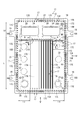
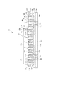
- the top view of the said case It is the side view of the said case, and the figure seen from the arrow IV side in FIG. It is the side view of the said case, and the figure seen from the arrow V side in FIG.
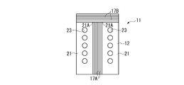
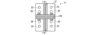
- the top view which shows the modification of this invention typically.
- the top view which shows the modification of this invention typically.
- the top view which shows the modification of this invention typically.
- FIG. 1 shows a front portion of a vehicle of a rigid dump truck as a construction machine according to the present embodiment.
- a cab 3 in which an operator gets into a position corresponding to the upper side of the front wheel 2 is provided on the front side of the dump truck 1.
- the cab 3 in addition to the operator seat 4 indicated by dotted lines, devices and devices (not shown) for running the dump truck 1 and raising and lowering the body 5 are installed.
- the monitor device 6 is installed above the front portion inside the cab 3.
- a metal mounting board 7 is provided at the lower rear portion inside the cab 3, and a controller 10 is attached to the mounting board 7.
- the monitor device 6 and the controller 10 are connected by a monitor cable 8A.
- One end of an image signal cable 8B is connected to the controller 10.
- the other end of the image signal cable 8B is connected to a plurality of monitoring cameras (not shown) mounted on the vehicle.
- the monitor cable 8 ⁇ / b> A and the image signal cable 8 ⁇ / b> B are integrally configured as a cable harness 8.
- the image signal from each surveillance camera is input to the controller 10 through the image signal cable 8B.
- the controller 10 performs predetermined processing based on the input image signal, and generates a display signal for an image to be displayed on the monitor device 6.
- the generated display signal is output to the monitor device 6 through the monitor cable 8A and displayed as a desired image. That is, in the present embodiment, the controller 10 is a controller for image processing.
- 2 to 5 are a perspective view, a plan view, a side view seen from the arrow IV side in FIG. 3, and a side view seen from the arrow V side in FIG. 3, respectively, showing the case 11 of the controller 10.
- the case 11 includes a bottomless box-shaped upper case 12 and a lower cover 13 that is screwed so as to close the bottom side of the upper case 12.
- Both the upper case 12 and the lower cover 13 are made of aluminum die casting.
- the upper case 12 is provided with a rectangular base 14 in plan view. On the upper surface 14 ⁇ / b> A of the base portion 14, a case main body portion 15 that protrudes upward is provided. A pair of long-side side surfaces 14B of the base portion 14 is provided with a mounting portion 16 having a long hole-like cutout portion 16A that protrudes horizontally toward the outside.
- the entire controller 10 is detachably attached to the attachment board 7 (FIG. 1) by a bolt inserted into the notch 16A of the attachment part 16.
- the inside of the case main body 15 that is also rectangular in plan view is an internal space having a predetermined volume.
- An electronic circuit board for generating a display signal in the monitor device 6 is accommodated in the internal space.
- An integrated circuit such as an FPGA (Field-Programmable Gate Array) configured for image processing is mounted on the electronic circuit board. Since the electronic circuit board including the integrated circuit is a heat generating component, it is necessary to promote heat dissipation from the heat generating component. Therefore, the upper case 12 and the lower cover 13 have a large number of heat dissipating fins 17 (17A, 17B, 17C, 17D). Is provided.
- first heat radiating fins 17 ⁇ / b> A parallel to the edge on the long side are protruded from the upper surface 15 ⁇ / b> A of the case body 15.
- the first heat dissipating fin 17A has a length L1 (FIG. 3), one end side in the longitudinal direction reaches the vicinity of one short side edge, and the other end side is the other short side edge.
- L1 FOG. 3
- the predetermined dimension L2 of the separated portion is a size at which a receptacle connector 26 described later can be disposed.
- a plurality of the first heat dissipating fins 17A are arranged in parallel along the short side direction of the case main body 15, but are collectively arranged at the center. That is, the first radiating fin 17A provided on both sides of the juxtaposed direction (same as the short side direction) and the long side edge are separated by a predetermined dimension L3 (FIG. 3).
- the predetermined dimension L3 is a size in which a receptacle connector 25 and the like to be described later can be arranged.
- a pair of second heat radiation fins 17B are provided at positions near the end of the first heat radiation fin 17A on the receptacle connector 26 side.
- the height positions of the upper ends of the first and second radiation fins 17A and 17B are the same.
- the second radiating fins 17B extend in the intersecting direction perpendicular to the first radiating fins 17A.
- one end of one of the second radiating fins 17B is continuous at a right angle to the first radiating fin 17A on one side in the side-by-side direction, and the other end is near the edge on the one long side.
- one end of the other second radiating fin 17B is continuous at a right angle to the first radiating fin 17A on the other side in the juxtaposed direction, and the other end is an edge on the other long side. The neighborhood has been reached.
- the first and second radiation fins 17A and 17B have the intersection A at the portion surrounded by the encircled circle (FIG. 3), and are arranged in a T shape as a whole in plan view.
- the three tip portions of the T-shape are extended to both the long-side edge and one short-side edge of the upper surface 15A.
- a plurality of rib-shaped third radiating fins 17 ⁇ / b> C straddling the upper surface 14 ⁇ / b> A of the base portion 14 are provided on the four side surfaces 15 ⁇ / b> B of the case main body portion 15.
- a plurality of fourth radiating fins 17 ⁇ / b> D are provided vertically downward on the lower surface 13 ⁇ / b> A (FIGS. 4 and 5) of the lower cover 13.
- the fourth heat dissipating fins 17D are provided in parallel to the long side edge of the lower cover 13 that is rectangular in plan view, and are provided over the entire area of the lower surface 13A. As shown in FIG. 5, the tip of the fourth radiating fin 17 ⁇ / b> D does not protrude from the lower surface that is the mounting surface of the mounting portion 16, and the mounting of the controller 10 to the mounting board 7 (FIG. 1) is not hindered. ing. Such fourth radiating fins 17 are exposed from the opening portion on the short side of the base portion 14, and the radiated heat is diffused from between the mounting plate 7 and the opening portion.
- the upper case 12 of the present embodiment also has the following configuration for protecting the connector.
- the first and second heat radiating fins 17A and 17B are arranged in a T shape on the upper surface 15A of the case main body 15, so that the first and second heat radiating are provided on the upper surface 15A as the surface.
- a pair of corners 21A surrounded by the intersection A of the fins 17A and 17B is formed.
- a region defined by the first and second radiation fins 17A and 17B is a pair of first connector arrangement surfaces 21 having corners 21A.
- These first connector arrangement surfaces 21 are formed on both sides of the region where the heat dissipating fins 17A are provided, and face both the long side edge and the one short side edge of the upper surface 15A.
- the outer edge of the other short side of the upper surface 15A (the side where the first heat dissipating fins 17A are not extended) is outside the partition region formed by the first and second heat dissipating fins 17A and 17B.
- positioning surface 22 which faces (side edge) is formed. That is, the second connector arrangement surface 22 is a region corresponding to the dimension L2 described above, and the height position thereof is slightly lower than that of the first connector arrangement surface 21.
- the first connector arrangement surface 21 is provided with a plurality of substantially circular connector arrangement holes 23. However, depending on the specifications of the controller 10, a part of the connector arrangement holes 23 may be used as a peephole, and it may be possible to check the lighting state of the LED mounted on the internal electronic circuit board. is there.
- the second connector arrangement surface 22 is provided with a pair of rectangular connector arrangement holes 24.
- a receptacle connector 25 as a connector is arranged in the connector arrangement hole 23 as represented by a two-dot chain line.
- a plug connector attached to the monitor cable 8A (FIG. 1) is connected to the receptacle connector 25 of the first connector arrangement surface 21.
- the plug connector attached to the video signal cable 8B (FIG. 1) is connected to the receptacle connector 25 on the other first connector arrangement surface 21.
- the height position of the receptacle connector 25 is lower than the height positions of the first and second radiation fins 17A and 17B, and the upper portion of the receptacle connector 25 is the first and second radiation fins. It does not protrude from 17A and 17B.
- illustration of the connectors arranged in the other connector arrangement holes 23 is omitted, the height positions of the connectors are the same as those of the first and second radiation fins 17A and 17B.
- the connector (not shown) is not necessarily the same as the receptacle connector 25, and may be a network cable connector or a USB (UniversalUniversSerial Bus) cable connector.
- a receptacle connector 26 is attached to the connector arrangement hole 24 as shown by a two-dot chain line.
- a plug connector 27 of the cable harness 9 is connected to the receptacle connector 26.
- the cable harness 9 has a configuration in which a plurality of conductive cables 9A such as a power cable for supplying power to an electronic circuit board, a signal cable used for signal transmission between peripheral devices, and a ground cable 9B for a frame ground are combined. is there.
- the height position of the receptacle connector 26 is lower than the height positions of the first and second radiation fins 17A, 17B, and the upper portion of the receptacle connector 26 is It does not protrude from the first and second radiation fins 17A and 17B.
- the height positions of the receptacle connectors 25 and 26 and other connectors are lower than the height positions of the first and second radiation fins 17A and 17B.
- the cable harnesses 8 and 9 etc. to be wired are The cable harnesses 8 and 9 do not cover the first and second radiating fins 17A and 17B by being outwardly passed from the first and second connector placement surfaces 21 and 22 through the edge. Does not interfere with heat dissipation performance.
- a connection portion 28 for connecting the ground cable 9B is provided on the upper surface 15A of the case main body portion 15 in the vicinity of the one connector arrangement hole 24.
- a screw hole 28A is formed in the connection portion 28.
- a screw 30 is inserted into a terminal of the ground cable 9B through a washer 29, and the screw 30 is screwed into the screw hole 28A. By doing so, the ground cable 9B is connected to the upper case 12, and the entire case 11 including the lower cover 13 is grounded to the frame ground.
- the case 11 is grounded by attaching the terminal of the ground cable 9B between the attachment portion 16 provided on the upper case 12 and the attachment plate 7 when the controller 10 is attached to the attachment plate 7 together with the attachment portion 16.
- the ground cable 9B and the case 11 are electrically connected.
- the connection part 28 for exclusive use of the ground cable 9B is provided in the upper case 12 of the case 11.
- the cable harness 9 is once removed from the controller 10 in a narrow work space, it is not necessary to remove a large bolt for attaching the controller 10, and it is only necessary to remove the dedicated screw 30. Easy maintenance. Further, when the ground cable 9B is connected, the screw 30 can be tightened while visually observing the tightening portion of the terminal. Therefore, the terminal is firmly connected to the case 11 and the ground cable 9B and the case 11 are electrically connected. The case 11 can be stably grounded to the frame ground.
- the present invention is not limited to the above-described embodiments, and modifications, improvements, and the like within the scope that can achieve the object of the present invention are included in the present invention.
- the first and second radiation fins 17A and 17B are arranged in a T shape so that the first and second connector arrangement surfaces 21 and 22 are formed on the upper surface 15A.
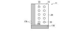
- the first and second radiating fins 17A and 17B may be arranged in an overall cross shape to form four connector arrangement surfaces 20, and as shown in FIG.
- One large connector arrangement surface 20 may be formed in a letter shape.
- symbol 20A in a figure has shown the corner part.
- the second heat radiation fins 17B are provided continuously with some of the first heat radiation fins 17A, but a slight gap is formed between the first and second heat radiation fins 17A and 17B. Even if they are provided discontinuously, they are included in the present invention.
- connection portion 28 for connecting the ground cable 9B is provided at one place.
- a pair of pairs are separated from each other diagonally on the case surface. You may provide a connection part.
- each cable harness connected to the connector adjacent to each connection portion is configured to include a ground cable.
- connection portion 28 is provided on the upper surface 15A of the case main body portion 15 .
- the connector arrangement hole on the side surface is provided. You may provide the grounding part of a ground cable in the vicinity. That is, in the present invention, the surface on which the connector is arranged is not limited to the upper surface, and may be a side surface.
- the number of connector arrangement holes, the type of connector, the type of cable harness, the function of the electronic circuit board accommodated in the case, etc. are not limited to those described in the above embodiment, and the use of the controller is taken into consideration. And may be arbitrarily determined.
- the present invention can be used not only as a controller mounted on a dump truck, but also as a controller for construction machines such as a power shovel, a wheel loader, and a bulldozer.
Landscapes
- Engineering & Computer Science (AREA)
- Microelectronics & Electronic Packaging (AREA)
- Mechanical Engineering (AREA)
- Physics & Mathematics (AREA)
- Thermal Sciences (AREA)
- Mining & Mineral Resources (AREA)
- Civil Engineering (AREA)
- General Engineering & Computer Science (AREA)
- Structural Engineering (AREA)
- Cooling Or The Like Of Electrical Apparatus (AREA)
- Connection Or Junction Boxes (AREA)
- Connector Housings Or Holding Contact Members (AREA)
Description
図1には、本実施形態の建設機械としてのリジット型ダンプトラックについて、その車両の前側部分が示されている。
図2~図5において、ケース11は、無底箱状の上部ケース12と、上部ケース12の底側を塞ぐようにねじ止めされる下部カバー13とを備える。上部ケース12および下部カバー13は共に、アルミのダイカスト(ダイキャスト)製である。
上部ケース12においては、ケース本体部15の上面15Aに第1、第2放熱フィン17A,17BがT字形状に配置されていることで、表面としての上面15Aには、第1、第2放熱フィン17A,17Bの交差部Aで囲まれた一対の隅部21Aが形成されている。そして、第1、第2放熱フィン17A,17Bで区画される領域は、隅部21Aを有する一対の第1コネクタ配置面21となっている。これらの第1コネクタ配置面21は、放熱フィン17Aが設けられた領域の両側に形成され、上面15Aの長辺側の辺縁および一方の短辺側の辺縁の両方に臨んでいる。
例えば、前記実施形態では、上面15Aには第1、第2コネクタ配置面21,22が形成されるよう、第1、第2放熱フィン17A,17BがT字形状に配置されていたが、図6Aに示すように、一対の第1コネクタ配置面21のみが形成されるよう、第1、第2放熱フィン17A,17Bを上面15Aの全体にわたってT字形状に配置してもよい。
また、図6Bに示すように、第1、第2放熱フィン17A,17Bを、全体十字形状に配置し、4つのコネクタ配置面20を形成してもよく、図6Cに示すように、全体L字形状に配置して1つの大きなコネクタ配置面20を形成してもよい。なお、図中の符号20Aは隅部を指している。
Claims (3)
- 建設機械に搭載されるとともに、表面にコネクタを配置するためのコネクタ配置孔が設けられているケースを備えたコントローラの接地構造において、
前記コネクタには、グランドケーブルを含む複数のケーブルで構成されたケーブルハーネスが接続され、
前記表面の前記コネクタ配置孔の近傍には、前記グランドケーブルが接続される接続部が設けられている
ことを特徴とする建設機械に搭載されるコントローラの接地構造。 - 請求項1に記載の建設機械に搭載されるコントローラの接地構造において、
前記表面には、複数の放熱フィンが設けられ、
前記コネクタの高さは、前記放熱フィンの高さよりも低い
ことを特徴とする建設機械に搭載されるコントローラの接地構造。 - 建設機械に搭載されるとともに、表面に複数の放熱フィンが設けられ、かつ前記表面にコネクタを配置するためのコネクタ配置孔が設けられているケースを備えたコントローラの接地構造において、
前記表面は、平面視で矩形状とされ、
前記放熱フィンとしては、交差部を有して互いに交差方向に配置された第1放熱フィンと第2放熱フィンとが設けられ、
前記第1放熱フィンと前記第2放熱フィンとは連続しているとともに、全体としてT字形状に配置され、かつT字形状での3方の先端部が前記表面の両方の長辺側の辺縁および一方の短辺側の辺縁まで延設されており、
前記表面には、前記交差部で囲まれる隅部を有し、かつ前記長辺側の辺縁および前記一方の短辺側の辺縁の両方に臨む一対の第1コネクタ配置面と、前記第1放熱フィンと前記第2放熱フィンとの区画領域の外方にて前記表面の他方の短辺側の辺縁に臨む第2コネクタ配置面とが形成され、
前記一対の第1コネクタ配置面および前記第2コネクタ配置面のそれぞれに、複数の前記コネクタ配置孔が設けられ、
前記第1、第2コネクタ配置面に配置される前記コネクタの高さは、前記第1放熱フィンおよび前記第2放熱フィンの高さよりも低く、
複数の前記コネクタ配置孔に設けられる少なくとも1つのコネクタには、グランドケーブルを含む複数のケーブルで構成されたケーブルハーネスが接続され、
前記表面の前記少なくとも1つのコネクタが配置されるコネクタ配置孔の近傍には、前記グランドケーブルが接続される接続部が設けられている
ことを特徴とする建設機械に搭載されるコントローラの接地構造。
Priority Applications (4)
| Application Number | Priority Date | Filing Date | Title |
|---|---|---|---|
| CN201280002470.0A CN103828159B (zh) | 2012-09-20 | 2012-10-29 | 搭载在建设机械上的控制器的接地结构 |
| DE112012005114.9T DE112012005114B4 (de) | 2012-09-20 | 2012-10-29 | Erdungsstruktur einer in einer Baumaschine installierten Steuereinrichtung |
| US13/816,658 US9723754B2 (en) | 2012-09-20 | 2012-10-29 | Ground structure of controller mounted in construction machine |
| KR1020137003959A KR101508149B1 (ko) | 2012-09-20 | 2012-10-29 | 건설 기계에 탑재되는 컨트롤러의 접지 구조 |
Applications Claiming Priority (2)
| Application Number | Priority Date | Filing Date | Title |
|---|---|---|---|
| JP2012-207145 | 2012-09-20 | ||
| JP2012207145A JP5486061B2 (ja) | 2012-09-20 | 2012-09-20 | 建設機械に搭載されるコントローラの接地構造 |
Publications (1)
| Publication Number | Publication Date |
|---|---|
| WO2014045461A1 true WO2014045461A1 (ja) | 2014-03-27 |
Family
ID=50340807
Family Applications (1)
| Application Number | Title | Priority Date | Filing Date |
|---|---|---|---|
| PCT/JP2012/077837 Ceased WO2014045461A1 (ja) | 2012-09-20 | 2012-10-29 | 建設機械に搭載されるコントローラの接地構造 |
Country Status (6)
| Country | Link |
|---|---|
| US (1) | US9723754B2 (ja) |
| JP (1) | JP5486061B2 (ja) |
| KR (1) | KR101508149B1 (ja) |
| CN (1) | CN103828159B (ja) |
| DE (1) | DE112012005114B4 (ja) |
| WO (1) | WO2014045461A1 (ja) |
Families Citing this family (1)
| Publication number | Priority date | Publication date | Assignee | Title |
|---|---|---|---|---|
| JP2017089139A (ja) * | 2015-11-04 | 2017-05-25 | 住友建機株式会社 | ショベル |
Citations (3)
| Publication number | Priority date | Publication date | Assignee | Title |
|---|---|---|---|---|
| JPH02109281A (ja) * | 1988-10-17 | 1990-04-20 | Mazda Motor Corp | 電装品のアース接続構造及び金属基板を有する集積回路 |
| JP2001025136A (ja) * | 1999-07-09 | 2001-01-26 | Sumitomo Wiring Syst Ltd | ジョイント接続構造を備えた電気接続箱 |
| JP2005143265A (ja) * | 2003-11-10 | 2005-06-02 | Yazaki Corp | 電気接続箱 |
Family Cites Families (18)
| Publication number | Priority date | Publication date | Assignee | Title |
|---|---|---|---|---|
| US3364395A (en) * | 1965-01-26 | 1968-01-16 | Burroughs Corp | Modular data processing apparatus including heat dissipating means |
| US3541433A (en) * | 1968-11-12 | 1970-11-17 | Ariel R Davis | Current supply apparatuses with an inductive winding and heat sink for solid state devices |
| GB1543678A (en) * | 1976-07-16 | 1979-04-04 | Lapp Kg U | Clamping device for cables leads hoses or the like |
| US4025139A (en) | 1976-08-30 | 1977-05-24 | The Raymond Lee Organization, Inc. | Redundant electrical grounding system |
| NL8902429A (nl) * | 1989-09-29 | 1991-04-16 | Du Pont Nederland | Filterconnector met vergrendelbaar montageframe. |
| US5608611A (en) * | 1995-10-03 | 1997-03-04 | United Technologies Automotive, Inc./Ford Motor Company | Vehicle electronic module with integral mounting and grounding means |
| DE19754694A1 (de) | 1997-12-10 | 1999-06-17 | Vem Motors Gmbh Elektromotoren | Adapterplatte zur Befestigung von Klemmenkästen an Stranggepreßten Gehäusen für Elektromotoren |
| JP2001135419A (ja) * | 1999-11-09 | 2001-05-18 | Auto Network Gijutsu Kenkyusho:Kk | シールドケーブルの端末処理方法及び端末処理構造 |
| US6595789B2 (en) * | 2000-10-20 | 2003-07-22 | Autonetworks Technologies, Ltd. | Electronic unit, shield cable connecting structure, connecting method, wires waterproof-connecting structure, and method |
| JP2005143264A (ja) | 2003-11-10 | 2005-06-02 | Yazaki Corp | 電気接続箱 |
| JP2005316475A (ja) * | 2004-04-29 | 2005-11-10 | Sumitomo Electric Ind Ltd | 光トランシーバ |
| US7061766B2 (en) * | 2004-09-23 | 2006-06-13 | Hamilton Sunstrand Corporation | Combination IGBT mounting method |
| US7210947B1 (en) * | 2006-01-13 | 2007-05-01 | Schweitzer Engineering Laboratories, Inc. | Cable harness system, ground clips and method for electrically grounding a conductor of the cable harness system |
| US7515423B2 (en) * | 2006-09-22 | 2009-04-07 | Fu Zhun Precision Industry (Shen Zhen) Co., Ltd. | Heat dissipation device |
| JP2008140803A (ja) * | 2006-11-30 | 2008-06-19 | Fuji Electric Fa Components & Systems Co Ltd | ヒートシンク |
| US7288717B1 (en) | 2007-03-08 | 2007-10-30 | Jin Hsin Ho Mold Enterprise Co., Ltd. | Electrical box assembly for a solar energy module |
| CN201248017Y (zh) | 2008-08-27 | 2009-05-27 | 苏州中超信息科技有限公司 | 太阳能光伏发电组件接线盒 |
| TWI479977B (zh) * | 2012-03-23 | 2015-04-01 | 緯創資通股份有限公司 | 散熱結構組合及其彈性固定組件 |
-
2012
- 2012-09-20 JP JP2012207145A patent/JP5486061B2/ja not_active Expired - Fee Related
- 2012-10-29 US US13/816,658 patent/US9723754B2/en active Active
- 2012-10-29 CN CN201280002470.0A patent/CN103828159B/zh active Active
- 2012-10-29 KR KR1020137003959A patent/KR101508149B1/ko active Active
- 2012-10-29 WO PCT/JP2012/077837 patent/WO2014045461A1/ja not_active Ceased
- 2012-10-29 DE DE112012005114.9T patent/DE112012005114B4/de active Active
Patent Citations (3)
| Publication number | Priority date | Publication date | Assignee | Title |
|---|---|---|---|---|
| JPH02109281A (ja) * | 1988-10-17 | 1990-04-20 | Mazda Motor Corp | 電装品のアース接続構造及び金属基板を有する集積回路 |
| JP2001025136A (ja) * | 1999-07-09 | 2001-01-26 | Sumitomo Wiring Syst Ltd | ジョイント接続構造を備えた電気接続箱 |
| JP2005143265A (ja) * | 2003-11-10 | 2005-06-02 | Yazaki Corp | 電気接続箱 |
Also Published As
| Publication number | Publication date |
|---|---|
| JP5486061B2 (ja) | 2014-05-07 |
| DE112012005114T5 (de) | 2014-09-18 |
| CN103828159B (zh) | 2016-10-19 |
| DE112012005114B4 (de) | 2018-03-15 |
| JP2014064366A (ja) | 2014-04-10 |
| US20140345935A1 (en) | 2014-11-27 |
| KR101508149B1 (ko) | 2015-04-07 |
| KR20140078574A (ko) | 2014-06-25 |
| CN103828159A (zh) | 2014-05-28 |
| US9723754B2 (en) | 2017-08-01 |
Similar Documents
| Publication | Publication Date | Title |
|---|---|---|
| JP6278243B2 (ja) | 蓄電ユニット | |
| JP5811986B2 (ja) | 電気接続箱 | |
| JP5236109B1 (ja) | 建設機械に搭載されるコントローラ | |
| US7108519B2 (en) | Electrical connection box | |
| US10391955B2 (en) | Electrical junction box | |
| US8952562B2 (en) | Controller mounted in construction machine | |
| JP2011097710A (ja) | 電気接続箱 | |
| CN106486941A (zh) | 电气接线箱和线束 | |
| US10608420B2 (en) | Heat dispersion structure of on-vehicle device | |
| WO2014061727A1 (ja) | シールドコネクタ | |
| JP5723861B2 (ja) | 電子機器のシールド構造 | |
| JP5486061B2 (ja) | 建設機械に搭載されるコントローラの接地構造 | |
| EP2151895A2 (en) | A nut and a housing | |
| JP3031230B2 (ja) | 電気接続箱の放熱構造 | |
| US7371085B2 (en) | Connector attachment structure for electronic apparatus | |
| CN117037634B (zh) | Led显示装置 | |
| EP2720521B1 (en) | Electrical connection box | |
| CN211630735U (zh) | 屏蔽罩、车载装置和新能源汽车 | |
| CN210350496U (zh) | 一种便捷配电控制箱 | |
| JP2024072682A (ja) | 電気接続箱 | |
| KR101312250B1 (ko) | 디-써브 커넥터 그라운딩 보조장치 | |
| CN102955499A (zh) | 蓝牙模组固定装置 | |
| JP3321062B2 (ja) | 配線接続装置 |
Legal Events
| Date | Code | Title | Description |
|---|---|---|---|
| WWE | Wipo information: entry into national phase |
Ref document number: 13816658 Country of ref document: US |
|
| ENP | Entry into the national phase |
Ref document number: 20137003959 Country of ref document: KR Kind code of ref document: A |
|
| WWE | Wipo information: entry into national phase |
Ref document number: 112012005114 Country of ref document: DE Ref document number: 1120120051149 Country of ref document: DE |
|
| 121 | Ep: the epo has been informed by wipo that ep was designated in this application |
Ref document number: 12885137 Country of ref document: EP Kind code of ref document: A1 |
|
| 122 | Ep: pct application non-entry in european phase |
Ref document number: 12885137 Country of ref document: EP Kind code of ref document: A1 |