WO2014042096A1 - Système médical - Google Patents
Système médical Download PDFInfo
- Publication number
- WO2014042096A1 WO2014042096A1 PCT/JP2013/074101 JP2013074101W WO2014042096A1 WO 2014042096 A1 WO2014042096 A1 WO 2014042096A1 JP 2013074101 W JP2013074101 W JP 2013074101W WO 2014042096 A1 WO2014042096 A1 WO 2014042096A1
- Authority
- WO
- WIPO (PCT)
- Prior art keywords
- unit
- image
- signal
- magnetic field
- capsule endoscope
- Prior art date
Links
Images


Classifications
-
- A—HUMAN NECESSITIES
- A61—MEDICAL OR VETERINARY SCIENCE; HYGIENE
- A61B—DIAGNOSIS; SURGERY; IDENTIFICATION
- A61B1/00—Instruments for performing medical examinations of the interior of cavities or tubes of the body by visual or photographical inspection, e.g. endoscopes; Illuminating arrangements therefor
- A61B1/00002—Operational features of endoscopes
- A61B1/00004—Operational features of endoscopes characterised by electronic signal processing
- A61B1/00009—Operational features of endoscopes characterised by electronic signal processing of image signals during a use of endoscope
- A61B1/000094—Operational features of endoscopes characterised by electronic signal processing of image signals during a use of endoscope extracting biological structures
-
- A—HUMAN NECESSITIES
- A61—MEDICAL OR VETERINARY SCIENCE; HYGIENE
- A61B—DIAGNOSIS; SURGERY; IDENTIFICATION
- A61B1/00—Instruments for performing medical examinations of the interior of cavities or tubes of the body by visual or photographical inspection, e.g. endoscopes; Illuminating arrangements therefor
- A61B1/00002—Operational features of endoscopes
- A61B1/00011—Operational features of endoscopes characterised by signal transmission
- A61B1/00016—Operational features of endoscopes characterised by signal transmission using wireless means
-
- A—HUMAN NECESSITIES
- A61—MEDICAL OR VETERINARY SCIENCE; HYGIENE
- A61B—DIAGNOSIS; SURGERY; IDENTIFICATION
- A61B1/00—Instruments for performing medical examinations of the interior of cavities or tubes of the body by visual or photographical inspection, e.g. endoscopes; Illuminating arrangements therefor
- A61B1/00002—Operational features of endoscopes
- A61B1/00025—Operational features of endoscopes characterised by power management
- A61B1/00036—Means for power saving, e.g. sleeping mode
-
- A—HUMAN NECESSITIES
- A61—MEDICAL OR VETERINARY SCIENCE; HYGIENE
- A61B—DIAGNOSIS; SURGERY; IDENTIFICATION
- A61B1/00—Instruments for performing medical examinations of the interior of cavities or tubes of the body by visual or photographical inspection, e.g. endoscopes; Illuminating arrangements therefor
- A61B1/00002—Operational features of endoscopes
- A61B1/00043—Operational features of endoscopes provided with output arrangements
- A61B1/00055—Operational features of endoscopes provided with output arrangements for alerting the user
-
- A—HUMAN NECESSITIES
- A61—MEDICAL OR VETERINARY SCIENCE; HYGIENE
- A61B—DIAGNOSIS; SURGERY; IDENTIFICATION
- A61B1/00—Instruments for performing medical examinations of the interior of cavities or tubes of the body by visual or photographical inspection, e.g. endoscopes; Illuminating arrangements therefor
- A61B1/04—Instruments for performing medical examinations of the interior of cavities or tubes of the body by visual or photographical inspection, e.g. endoscopes; Illuminating arrangements therefor combined with photographic or television appliances
- A61B1/041—Capsule endoscopes for imaging
-
- A—HUMAN NECESSITIES
- A61—MEDICAL OR VETERINARY SCIENCE; HYGIENE
- A61B—DIAGNOSIS; SURGERY; IDENTIFICATION
- A61B5/00—Measuring for diagnostic purposes; Identification of persons
- A61B5/06—Devices, other than using radiation, for detecting or locating foreign bodies ; determining position of probes within or on the body of the patient
- A61B5/065—Determining position of the probe employing exclusively positioning means located on or in the probe, e.g. using position sensors arranged on the probe
-
- A—HUMAN NECESSITIES
- A61—MEDICAL OR VETERINARY SCIENCE; HYGIENE
- A61B—DIAGNOSIS; SURGERY; IDENTIFICATION
- A61B1/00—Instruments for performing medical examinations of the interior of cavities or tubes of the body by visual or photographical inspection, e.g. endoscopes; Illuminating arrangements therefor
- A61B1/00002—Operational features of endoscopes
- A61B1/00025—Operational features of endoscopes characterised by power management
- A61B1/00027—Operational features of endoscopes characterised by power management characterised by power supply
- A61B1/00032—Operational features of endoscopes characterised by power management characterised by power supply internally powered
-
- A—HUMAN NECESSITIES
- A61—MEDICAL OR VETERINARY SCIENCE; HYGIENE
- A61B—DIAGNOSIS; SURGERY; IDENTIFICATION
- A61B2560/00—Constructional details of operational features of apparatus; Accessories for medical measuring apparatus
- A61B2560/02—Operational features
- A61B2560/0204—Operational features of power management
-
- A—HUMAN NECESSITIES
- A61—MEDICAL OR VETERINARY SCIENCE; HYGIENE
- A61B—DIAGNOSIS; SURGERY; IDENTIFICATION
- A61B2560/00—Constructional details of operational features of apparatus; Accessories for medical measuring apparatus
- A61B2560/02—Operational features
- A61B2560/0266—Operational features for monitoring or limiting apparatus function
-
- A—HUMAN NECESSITIES
- A61—MEDICAL OR VETERINARY SCIENCE; HYGIENE
- A61B—DIAGNOSIS; SURGERY; IDENTIFICATION
- A61B5/00—Measuring for diagnostic purposes; Identification of persons
- A61B5/68—Arrangements of detecting, measuring or recording means, e.g. sensors, in relation to patient
- A61B5/6846—Arrangements of detecting, measuring or recording means, e.g. sensors, in relation to patient specially adapted to be brought in contact with an internal body part, i.e. invasive
- A61B5/6847—Arrangements of detecting, measuring or recording means, e.g. sensors, in relation to patient specially adapted to be brought in contact with an internal body part, i.e. invasive mounted on an invasive device
- A61B5/6861—Capsules, e.g. for swallowing or implanting
Definitions
- the present invention relates to a medical system capable of acquiring in-vivo image information using a capsule endoscope.
- Endoscopes in the medical field are conventionally used in applications such as in vivo observation.
- a subject is placed in a body cavity by swallowing, and an image of a subject is captured while moving in the body cavity with a peristaltic motion, and the captured subject image is externally captured as an imaging signal.
- capsule endoscopes capable of wireless transmission have been proposed.
- Japanese Patent Application Laid-Open No. 2009-89907 discloses activation and stop of the capsule endoscope by irradiating an alternating magnetic field from the outside of the capsule endoscope.
- the structure which can perform the change which concerns on is disclosed. That is, an ecological observation system disclosed in Japanese Patent Application Laid-Open No. 2009-89907 includes a capsule endoscope configured to have a size and shape that can be placed in a living body, and a capsule endoscope. And a magnetic field generation unit that generates an alternating magnetic field outside.
- the magnetic field generation unit has a configuration capable of switching the magnetic field generation state to either on or off in accordance with, for example, a switch operation by the user.
- a capsule endoscope is an illumination unit that emits illumination light for illuminating a subject in a living body, an imaging unit that captures an image of a subject illuminated by the illumination unit, and outputs the imaging signal, and an output from the imaging unit
- a wireless transmission unit that wirelessly transmits the captured imaging signal to the outside of the living body
- a power supply unit that supplies driving power required for driving each unit of the illumination unit, the imaging unit, and the wireless transmission unit, and an alternating current generated in the magnetic field generation unit
- a magnetic field detection unit capable of detecting the magnetic field.
- Japanese Patent Application Laid-Open No. 2009-89907 discloses an alternating magnetic field generated from a magnetic field generator after a capsule endoscope is placed in the body of a subject for the purpose of suppressing the consumption of the internal battery.
- a technique for appropriately switching on / off a power supply is disclosed. Specifically, for example, when passing through a site where observation or the like is not necessary, the power is turned off, and when the desired observation site is reached, an alternating magnetic field is generated from the magnetic field generator. Control to turn on the power of the capsule endoscope is possible. Furthermore, when a part that does not require observation or the like is reached, the capsule endoscope can be powered off by generating an alternating magnetic field again from the magnetic field generator.
- the present invention has been made in view of the above circumstances, and an object of the present invention is to provide a medical system that can suppress consumption of a power source and can obtain a desired image without burdening an observer.
- a medical system includes an image acquisition unit that acquires an image, an image signal transmission unit that wirelessly transmits the image, and a power source that can supply power to the image acquisition unit and the image signal transmission unit
- a control signal receiving unit that receives a control signal transmitted from the outside, and a switch unit that switches an on / off state of power supply from the power supply unit to the image acquisition unit and the image signal transmission unit according to the control signal
- a capsule endoscope that is swallowed by a subject, an image signal receiving unit that receives the image signal, and whether the capsule endoscope is in a predetermined digestive tract by analysis of the image
- a signal control for performing output control of the control signal for causing the image acquisition unit and the image signal transmission unit to operate continuously or intermittently according to a determination result of the determination unit.
- functional block diagram showing the main part of the capsule endoscope Same as above, functional block diagram showing the main part of the extracorporeal device Same as above, flowchart showing operation mode control routine
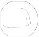
- the figure which shows an example of the image imaged with the stomach same as above The figure which shows typically an example of the image imaged by the duodenal bulb part as above
- the flowchart showing the first modification of the operation mode control routine The flowchart showing the second modification of the operation mode control routine
- FIG. 1 is a schematic configuration diagram of a medical system used for a subject
- FIG. 2 is a functional block diagram showing a main part of a capsule endoscope
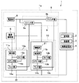
- 3 is a functional block diagram showing the main part of the extracorporeal device
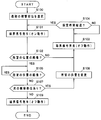
- FIG. 4 is a flowchart showing an operation mode control routine
- FIG. 5 is a diagram schematically showing an example of an image captured on the stomach
- FIG. 6 is a duodenal bulb part.
- FIG. 7 is a diagram schematically showing an example of an image captured in the small intestine
- FIG. 8 is a flowchart showing a first modification of the operation mode control routine
- FIG. 9 is a flowchart showing a second modification of the operation mode control routine.
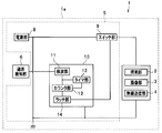
- a medical system 50 shown in FIG. 1 includes various information between a swallowable capsule endoscope 1 introduced into a body cavity of a subject 100 and the capsule endoscope 1 arranged outside the subject 100. And an extracorporeal device 30 for wireless communication.
- the capsule endoscope 1 captures image data by capturing an illumination unit 2 that emits illumination light for illuminating a subject in the body cavity of the subject 100, and a subject illuminated by the illumination unit.
- An imaging unit 3 to be acquired a wireless transmission unit 4 as an image signal transmission unit that modulates image data acquired by the imaging unit 3 into a wireless signal and transmits the signal to the outside, an illumination unit 2, an imaging unit 3, and a wireless transmission unit
- a power supply unit 5 capable of supplying driving power for driving the respective units 4
- a magnetic field detection unit 6 capable of detecting a magnetic field generated in the extracorporeal device 30 (for example, a plurality of burst AC magnetic fields),
- the image acquisition unit in the present embodiment includes, for example, the illumination unit 2 and the imaging unit 3.
- the power supply unit 5 includes a power supply unit 8 including a built-in battery that can supply power for driving each unit of the capsule endoscope 1, a switch unit 9, and a signal reception unit 10. Has been.
- the magnetic field detection unit 6 is configured by a resonance circuit including a coil and a capacitor, for example.
- the magnetic field detection unit 6 generates a magnetic field detection signal that is an electrical signal corresponding to a detection result (for example, a waveform at the time of detection) of the AC magnetic field generated from the extracorporeal device 30 and outputs the magnetic field detection signal to the signal reception unit 10.
- the power supply unit 8 is connected so as to constantly supply power to the signal receiving unit 10 and supply power to each of the illumination unit 2, the imaging unit 3, and the wireless transmission unit 4 via the switch unit 9.
- the switch unit 9 is connected between each unit of the illumination unit 2, the imaging unit 3, and the wireless transmission unit 4 and the power supply unit 8, and is turned on or off based on the output state of the switching signal from the signal reception unit 10. As a result, the power supply state from the power supply unit 8 to each unit of the illumination unit 2, the imaging unit 3, and the wireless transmission unit 4 can be switched between a conduction state and an open state.
- the signal receiving unit 10 detects a magnetic field detection signal having a signal level equal to or higher than a preset threshold and outputs a pulse signal, and a certain time has elapsed since the detection unit 11 started to output the pulse signal.
- the timer unit 12 that measures the time until the signal is received, the counter unit 13 that obtains a count value by counting the number of times the pulse signal is input from the detection unit 11 one by one, and the output signal from the counter unit 13 are input.
- a latch unit 14 that inverts the output of a switching signal for switching the on / off state of the switch unit 9 every time.
- the detection unit 11 is configured by, for example, a peak hold circuit including a diode, a capacitor, and a resistor. That is, the detection unit 11 is output from the magnetic field detection unit 6 when the output interval of the magnetic field detection signal output from the magnetic field detection unit 6 is equal to or greater than the time constant ⁇ determined by the product of the capacitance of the capacitor and the resistance value. The magnetic field detection signal is appropriately detected. And the detection part 11 can detect a magnetic field detection signal output from the magnetic field detection part 6 appropriately by detecting the magnetic field detection signal output from the extracorporeal apparatus 30 for every output interval more than time constant (tau). It is configured.
- a peak hold circuit including a diode, a capacitor, and a resistor. That is, the detection unit 11 is output from the magnetic field detection unit 6 when the output interval of the magnetic field detection signal output from the magnetic field detection unit 6 is equal to or greater than the time constant ⁇ determined by the product of the capacitance of the capacitor and the resistance value.
- the magnetic field detection signal is appropriately
- the detection unit 11 detects the magnetic field detection signal output from the magnetic field detection unit 6 at every output interval equal to or greater than the time constant ⁇ , thereby matching the number of output of the alternating magnetic field output from the extracorporeal device 30 in a burst shape.
- the number of pulse signals to be output can be continuously output to the counter unit 13.
- the timer unit 12 operates to reset the count value of the counter unit 13 to 0 when a certain time has elapsed.
- the counter unit 13 outputs an output signal to the latch unit 14 when detecting that the count value obtained by counting the number of input of the pulse signal from the detection unit 11 by one reaches the signal output count value. It is configured.
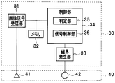
- the extracorporeal device 30 includes an image signal receiving unit 31, a memory 32, a magnetic field generation unit 33, and a control unit 34.
- the image signal receiving unit 31 receives the wireless signal transmitted from the wireless transmission unit 4 of the capsule endoscope 1 via the receiving antenna 41, and receives image data (endoscopic image data) from the received wireless signal. ).
- the memory 32 is configured by, for example, an external memory and stores the image data extracted by the image signal receiving unit 31.
- the magnetic field generator 33 has a configuration capable of generating a burst-like AC electric field for switching the power supply state in the capsule endoscope 1. Specifically, the magnetic field generation unit 33 generates a plurality of burst-like AC magnetic fields in response to an output instruction from the control unit 34, and is applied to the capsule endoscope 1 via the transmission antenna 42. To send.
- the control unit 34 includes a determination unit 35 and a signal control unit 36.
- the determination unit 35 determines whether or not the capsule endoscope 1 is in a predetermined digestive tract by analyzing the image.
- a pixel in which the luminance difference between adjacent pixels is equal to or greater than a predetermined value is detected as an edge.
- the most edges can be detected from the image of the small intestine where fine villi are present.
- almost no edge can be detected from the image of the substantially flat duodenal bulb.
- an edge having a predetermined length can be detected from an image of the stomach where a pleat of a predetermined length extends.
- the small intestine where fine villi are present has the largest luminance dispersion, followed by the stomach and the duodenal bulb.
- description is abbreviate
- the signal control unit 36 controls the image acquisition unit (the illumination unit 2 and the imaging unit 3) and the wireless transmission unit 4 to operate continuously or intermittently according to the determination result of the determination unit 35 (multiple bursts). (AC magnetic field) is controlled.
- the image acquisition unit and the wireless transmission unit 4 operate intermittently until the determination unit 35 determines that the capsule endoscope 1 has reached the small intestine.
- the control signal output control to the capsule endoscope 1 is performed so that the determination unit 35 determines that the capsule endoscope 1 has reached the small intestine
- the image acquisition unit and the wireless transmission unit 4 continuously
- the control output of the control signal to the capsule endoscope 1 is performed so as to operate.
- the receiving antenna 41 and the transmitting antenna 42 are disposed on a cover-type clothing (for example, a vest) 40 worn by the subject 100.
- a cover-type clothing for example, a vest
- This routine is executed, for example, when the capsule endoscope 1 is swallowed by the subject 100 and a switch (not shown) of the extracorporeal device 30 is turned on.
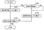
- the routine starts, first, in step S101, the control unit 34 generates a plurality of burst alternating magnetic fields through the magnetic field generation unit 33 so as to turn on the switch unit 9 of the capsule endoscope 1.
- the AC magnetic field is transmitted to the capsule endoscope 1 via the transmitting antenna 42 and received by the magnetic field detector 6 of the capsule endoscope 1. Then, the AC magnetic field received by the magnetic field detection unit 6 is converted into a magnetic field detection signal and then output to the signal reception unit 10.
- the signal receiving unit 10 turns on the switch unit 9, and power supply from the power supply unit 8 to the illumination unit 2, the imaging unit 3, and the wireless transmission unit 4 is started.
- the subject in the body cavity of the subject 100 is illuminated by the illuminating unit 2 and imaged by the imaging unit 3, and the image data of the imaged subject is modulated into a radio signal by the wireless transmission unit 4.
- a radio signal from the radio transmission unit 4 is received via the reception antenna 41.
- the received signal is demodulated into image data by the image signal receiving unit 31 of the extracorporeal device 30, and then stored in the memory 32 and appropriately input to the control unit 34.
- control unit 34 analyzes the latest image data input from the image signal receiving unit 31, and the currently acquired image is an image at a desired position in the digestive tract. Or not (for example, whether or not the image is a small intestine image).
- control unit 34 proceeds to step S103 to turn off the switch unit 9 of the capsule endoscope 1. Therefore, a plurality of burst-like AC signals are generated through the magnetic field generator 33.
- the AC magnetic field is transmitted to the capsule endoscope 1 via the transmitting antenna 42 and received by the magnetic field detector 6 of the capsule endoscope 1. Then, the AC magnetic field received by the magnetic field detection unit 6 is converted into a magnetic field detection signal and then output to the signal reception unit 10.
- the signal receiving unit 10 turns off the switch unit 9, and power supply from the power supply unit 8 to the illumination unit 2, the imaging unit 3, and the wireless transmission unit 4 is stopped.
- step S104 the control unit 34 checks whether or not the set time T has elapsed from the OFF operation of the switch unit 9. If it is determined that the set time T has not yet elapsed, the control unit 34 continues. stand by.
- step S104 when it is determined in step S104 that the set time T has elapsed from the off operation of the switch unit 9, the control unit 34 returns to step S101.
- step S101 to step S104 in the control unit 34 by performing a series of processes from step S101 to step S104 in the control unit 34, in the capsule endoscope 1, the illumination unit 2, the imaging unit 3, and the wireless transmission unit 4 are set for a set time. It is intermittently operated every T (that is, the capsule endoscope 1 is operated in the intermittent operation mode).
- step S102 If it is determined in step S102 that the currently acquired image is an image at a desired position as a result of the image analysis, the control unit 34 does not change the state of the capsule endoscope 1 as it is (that is, in step S101). The routine is exited while the switch section 9 is kept on.
- the operation mode control routine is completed while the switch unit 9 is turned on in this way, in the capsule endoscope 1, the illumination unit 2, the imaging unit 3, and the wireless transmission unit 4 are continuously connected. Operated (ie, the capsule endoscope is operated in the continuous operation mode).
- the capsule endoscope 1 is in the predetermined digestive tract by analyzing the image transmitted from the capsule endoscope 1 to the extracorporeal device 30 arranged outside the subject 100.
- the signal control unit 36 that performs output control of a control signal for operation, it is possible to suppress consumption of the power supply unit 8 of the capsule endoscope 1 without imposing a burden on the observer and Images can be obtained.
- the patient (subject 100) can move around freely.
- step S102 If it is determined in step S102 that the currently acquired image is an image at a desired position as a result of the image analysis, the control unit 34 proceeds to step S105.
- step S105 the control unit 34 performs an analysis process on the latest image data input from the image signal receiving unit 31 by an analysis process similar to that in step S102 described above, and the currently acquired image is stored in the digestive tract. It is determined whether the image is at a desired position (for example, whether the image is a small intestine image).
- step S105 when it is determined as a result of image analysis that the currently acquired image is an image at a desired position, the control unit 34 stands by and analyzes each time the latest image data is input. Repeat the process.
- step S105 if it is determined in step S105 that the currently acquired image is no longer the image at the desired position as a result of the image analysis, the control unit 34 proceeds to step S106, and the switch unit 9 of the capsule endoscope 1 is performed. In order to turn off the signal, a burst AC signal is generated a plurality of times through the magnetic field generator 33, and then the routine is exited.
- the control unit 34 selects the first observation site as a desired position prior to the processing in step S101. That is, for example, in the present modification in which images of the stomach and small intestine are acquired, the stomach is selected as a desired position.
- step S105 of this routine as a result of the image analysis, it is determined that the currently earned image is no longer the image at the desired position (in this variation, the currently selected stomach or small intestine image).
- the control unit 34 proceeds to step S107 and checks whether there is a next observation site as a desired observation site. That is, for example, in the present modification in which images of the stomach and the small intestine are acquired, it is checked whether or not the small intestine has not yet been selected as the desired position.
- step S107 If it is determined in step S107 that there is a next observation site, the control unit 34 proceeds to step S108, and after changing the desired position to the next observation site (for example, changing the desired position from the stomach to the small intestine). After changing to), the process returns to step S103.
- step S107 determines whether there is no next observation site. If it is determined in step S107 that there is no next observation site, the control unit 34 proceeds to step S109 and performs a plurality of operations through the magnetic field generation unit 33 to turn off the switch unit 9 of the capsule endoscope 1. After generating a burst of alternating current signals, the routine is exited.
- FIG. 10 relates to the second embodiment of the present invention
- FIG. 10 is a functional block diagram showing the main part of the capsule endoscope.
- the switch unit 9 includes two switch units 9a and 9b
- the signal reception unit 10 includes two signal reception units 10a and 10b. It differs mainly from the embodiment.
- symbol is attached
- the switch unit 9a is connected to the power supply unit 8, and is turned on or off based on the output state of the switching signal from the signal receiving unit 10a having the function as the first switching control unit. As a result, the power supply state from the power supply unit 8 to the signal receiving unit 10b can be switched to a conductive state or an open state.
- the switch unit 9b is connected between each unit of the illumination unit 2, the imaging unit 3, and the wireless transmission unit 4 and the power supply unit 8, and from the signal reception unit 10b having a function as a second switching control unit.
- the power supply state from the power supply unit 8 to each unit of the illumination unit 2, the imaging unit 3, and the wireless transmission unit 4 is switched to a conductive state or an open state by being turned on or off based on the output state of the switching signal. It is configured to be able to.
- the signal receiving unit 10a detects a magnetic field detection signal having a signal level equal to or higher than a threshold TH1 and outputs a pulse signal, and until a certain time TA1 has elapsed since the detection unit 11a started to output a pulse signal.
- a timer unit 12a that measures time
- a counter unit 13a that obtains a count value by counting the number of times a pulse signal is input from the detection unit 11a, and a switch each time an output signal is input from the counter unit 13a
- a latch unit 14a for inverting the output of a switching signal for switching the on / off state of the unit 9a.
- the detection unit 11a is configured by a peak hold circuit including, for example, a diode, a capacitor, and a resistor. That is, when the output interval of the magnetic field detection signal output from the magnetic field detection unit 6 is not less than the time constant ⁇ 1 determined by the product of the capacitance of the capacitor and the resistance value of the resistor, the detection unit 11a An output magnetic field detection signal can be appropriately detected.
- the detection part 11a detects the magnetic field detection signal output from the magnetic field detection part 6 for every output space
- the number of pulse signals corresponding to the number of magnetic field detection signals output from the magnetic field detection unit 6) can be continuously output to the counter unit 13a.
- the timer unit 12a operates to reset the count value of the counter unit 13a to 0 when a certain time TA1 has elapsed.
- the timer unit 12a of the present embodiment is not limited to measuring time until a certain time TA1 elapses after the detection unit 11a starts outputting a pulse signal.
- the pulse signal output from the detection unit 11a The time corresponding to the output interval may be measured, or the two times may be measured simultaneously.
- the timer unit 12a is configured to measure a time corresponding to the output interval of the pulse signal output from the detection unit 11a, the time constant ⁇ 1 and the measurement time of the timer unit 12a are You may make it substantially correspond.
- the counter unit 13a outputs an output signal to the latch unit 14a when detecting that the count value obtained by counting the number of input of the pulse signal from the detection unit 11a by one reaches the signal output count value PA. It is configured as follows.
- the signal receiving unit 10b amplifies the signal level of the magnetic field detection signal output from the magnetic field detection unit 6 to a signal level equal to or higher than the threshold value TH2, and the magnetic field detection signal having a signal level equal to or higher than the threshold value TH2.
- a detection unit 11b that detects and outputs a pulse signal, a timer unit 12b that measures time from when the detection unit 11b starts outputting a pulse signal until a predetermined time TA2 elapses, and an input of the pulse signal from the detection unit 11b
- a counter unit 13b that obtains a count value by counting the number of times one by one
- a latch unit 14b that inverts the output of a switching signal for switching the on / off state of the switch unit 9b every time an output signal from the counter unit 13b is input. And is configured.
- the signal receiving unit 10b of the present embodiment includes the amplifying unit 21, the detection sensitivity of the alternating magnetic field (control signal) generated by the magnetic field generating unit 33 is relatively higher than that of the signal receiving unit 10a. It is set to be.
- the detection unit 11b is configured by a peak hold circuit including, for example, a diode, a capacitor, and a resistor.
- the detection unit 11b receives the magnetic field detection signal from the magnetic field detection unit 6 when the output interval of the magnetic field detection signal output from the magnetic field detection unit 6 is not less than the time constant ⁇ 2 determined by the product of the capacitance of the capacitor and the resistance value of the resistor. An output magnetic field detection signal can be appropriately detected.
- the detection part 11a detects the magnetic field detection signal output from the magnetic field detection part 6 for every output space
- the number of pulse signals corresponding to the number of magnetic field detection signals output from the magnetic field detection unit 6) can be continuously output to the counter unit 13b.
- the timer unit 12b operates to reset the count value of the counter unit 13b to 0 when the predetermined time TA2 has elapsed.
- the timer unit 12b is not limited to measuring the time from when the detection unit 11b starts outputting a pulse signal until a predetermined time TA2 elapses.
- the timer unit 12b outputs a pulse signal output from the detection unit 11b.
- the time corresponding to the output interval may be measured, or the two times may be measured simultaneously.
- the timer unit 12b is configured to measure a time corresponding to the output interval of the pulse signal output from the detection unit 11b, the time constant ⁇ 2 and the measurement time of the timer unit 12b are You may make it correspond.
- the predetermined times TA1 and TA2 may be set to the same time, or may be set to satisfy TA1> TA2.
- the counter unit 13b When the counter unit 13b detects that the count value obtained by counting the number of input of the pulse signal from the detection unit 11b by one reaches the signal output count value PB, the counter unit 13b outputs the output signal to the latch unit 14b. It is configured as follows.
- the signal output count values PA and PB described above may be set to arbitrary values as long as they have a relationship of PA> PB.
- the capacitance of each capacitor and the resistance value of each resistor are set so that the time constant ⁇ 1 of the detection unit 11a and the time constant ⁇ 2 of the detection unit 11b have the same value. It is assumed that
- the switch unit 9a is turned on before being swallowed into the subject 100, and the on operation or the off operation due to the generation of the magnetic field signal in the above steps S101, S103, S106, and S109 This is performed for the unit 9b.
- a magnetic field for turning on / off the switch unit 9 a can be generated by the magnetic field generation unit 33 of the extracorporeal device 30.
- the magnetic field for turning on / off the switch unit 9 a may be generated by a magnetic field generation unit provided separately from the magnetic field generation unit 33.
- the same operational effects as those of the first embodiment described above can be achieved.
- the amplification of the amplification unit 21 does not cause an increase in the size of the magnetic field detection unit 6 or the like.
- the power supply state from the power supply unit 8 to the illumination unit 2, the imaging unit 3, and the wireless transmission unit 4 can be accurately switched between a conduction state and an open state. In this case, since the power from the power supply unit 8 is not supplied to the amplification unit 21 while the switch unit 9a is turned off, unnecessary power consumption can be accurately suppressed.
Abstract
Cette invention concerne un dispositif extracorporel (30) situé en dehors de l'organisme du sujet (100) et comportant : une unité de détermination (35) qui, d'après l'analyse d'une image transmise par une capsule vidéo-endoscopique (1), détermine si ladite capsule vidéo-endoscopique (1) se trouve dans une partie prédéterminée du tractus digestif ; et une unité de commande de signal (36) qui contrôle l'émission d'un signal de commande pour faire fonctionner de manière continue ou par intermittence l'unité d'acquisition d'image (unité d'éclairage (2) et unité d'imagerie (3)) et l'unité de transmission sans fil (4) de la capsule vidéo-endoscopique (1), en fonction du résultat de détermination fourni par l'unité de détermination (35). Le dispositif permet de réduire au minimum l'épuisement de l'unité source d'alimentation (8) de la capsule vidéo-endoscopique (1) sans imposer de charge à l'observateur, et d'obtenir l'image souhaitée.
Priority Applications (3)
| Application Number | Priority Date | Filing Date | Title |
|---|---|---|---|
| CN201380047394.XA CN104619234A (zh) | 2012-09-11 | 2013-09-06 | 医疗系统 |
| EP13837177.8A EP2896349A4 (fr) | 2012-09-11 | 2013-09-06 | Système médical |
| US14/623,702 US20150157195A1 (en) | 2012-09-11 | 2015-02-17 | Medical system |
Applications Claiming Priority (2)
| Application Number | Priority Date | Filing Date | Title |
|---|---|---|---|
| JP2012199545A JP6091118B2 (ja) | 2012-09-11 | 2012-09-11 | 医療システム |
| JP2012-199545 | 2012-09-11 |
Related Child Applications (1)
| Application Number | Title | Priority Date | Filing Date |
|---|---|---|---|
| US14/623,702 Continuation US20150157195A1 (en) | 2012-09-11 | 2015-02-17 | Medical system |
Publications (1)
| Publication Number | Publication Date |
|---|---|
| WO2014042096A1 true WO2014042096A1 (fr) | 2014-03-20 |
Family
ID=50278209
Family Applications (1)
| Application Number | Title | Priority Date | Filing Date |
|---|---|---|---|
| PCT/JP2013/074101 WO2014042096A1 (fr) | 2012-09-11 | 2013-09-06 | Système médical |
Country Status (5)
| Country | Link |
|---|---|
| US (1) | US20150157195A1 (fr) |
| EP (1) | EP2896349A4 (fr) |
| JP (1) | JP6091118B2 (fr) |
| CN (1) | CN104619234A (fr) |
| WO (1) | WO2014042096A1 (fr) |
Cited By (3)
| Publication number | Priority date | Publication date | Assignee | Title |
|---|---|---|---|---|
| JP5815166B1 (ja) * | 2014-05-26 | 2015-11-17 | オリンパス株式会社 | カプセル型内視鏡装置 |
| WO2015182185A1 (fr) * | 2014-05-26 | 2015-12-03 | オリンパス株式会社 | Appareil du type vidéocapsule endoscopique |
| EP3150102A4 (fr) * | 2014-05-27 | 2018-01-24 | Olympus Corporation | Endoscope à capsule |
Families Citing this family (4)
| Publication number | Priority date | Publication date | Assignee | Title |
|---|---|---|---|---|
| WO2014102768A1 (fr) * | 2012-12-31 | 2014-07-03 | Given Imaging Ltd. | Procédés et systèmes de commande d'un interrupteur marche/arrêt |
| CN104905757B (zh) * | 2015-06-30 | 2016-08-24 | 中国人民解放军成都军区总医院 | 具有超声感应的胶囊内镜 |
| CN105498078A (zh) * | 2016-03-07 | 2016-04-20 | 宁波力芯科信息科技有限公司 | 基于门禁认证及智能家居控制的智能药丸、系统和实现方法 |
| WO2018189800A1 (fr) * | 2017-04-11 | 2018-10-18 | 東京コスモス電機株式会社 | Système de détection d'informations biologiques et procédé de détection d'informations biologiques |
Citations (5)
| Publication number | Priority date | Publication date | Assignee | Title |
|---|---|---|---|---|
| JP2004041709A (ja) * | 2002-05-16 | 2004-02-12 | Olympus Corp | カプセル医療装置 |
| JP2004154176A (ja) * | 2002-11-01 | 2004-06-03 | Olympus Corp | 内視鏡撮像装置 |
| JP2008237640A (ja) * | 2007-03-28 | 2008-10-09 | Fujifilm Corp | カプセル内視鏡、およびカプセル内視鏡システム、並びにカプセル内視鏡の動作制御方法 |
| JP2008237639A (ja) * | 2007-03-28 | 2008-10-09 | Fujifilm Corp | カプセル内視鏡システム、およびカプセル内視鏡の動作制御方法 |
| JP2009089907A (ja) | 2007-10-09 | 2009-04-30 | Olympus Corp | 生体情報取得装置、生体観察システム及び生体観察システムの駆動方法 |
Family Cites Families (7)
| Publication number | Priority date | Publication date | Assignee | Title |
|---|---|---|---|---|
| JP5057651B2 (ja) * | 2005-02-15 | 2012-10-24 | オリンパス株式会社 | 管腔画像処理装置、管腔画像処理方法及びそのためのプログラム |
| JP2007082664A (ja) * | 2005-09-21 | 2007-04-05 | Fujifilm Corp | カプセル内視鏡 |
| WO2007083708A1 (fr) * | 2006-01-19 | 2007-07-26 | Olympus Medical Systems Corp. | Système médical in vivo, méthode d’utilisation d'un appareil insérable dans un corps et méthode chirurgicale |
| KR100876673B1 (ko) * | 2007-09-06 | 2009-01-07 | 아이쓰리시스템 주식회사 | 촬영 속도 조절이 가능한 캡슐형 내시경 |
| JP5284846B2 (ja) * | 2009-03-30 | 2013-09-11 | オリンパス株式会社 | 生体内観察システム、該生体内観察システムの作動方法 |
| CN101669809B (zh) * | 2009-09-24 | 2010-12-01 | 上海交通大学 | 主动可控式胶囊内镜机器人系统 |
| WO2011061746A1 (fr) * | 2009-11-20 | 2011-05-26 | Given Imaging Ltd. | Système et procédé de contrôle de la consommation d'énergie d'un dispositif in vivo |
-
2012
- 2012-09-11 JP JP2012199545A patent/JP6091118B2/ja active Active
-
2013
- 2013-09-06 WO PCT/JP2013/074101 patent/WO2014042096A1/fr unknown
- 2013-09-06 CN CN201380047394.XA patent/CN104619234A/zh active Pending
- 2013-09-06 EP EP13837177.8A patent/EP2896349A4/fr not_active Withdrawn
-
2015
- 2015-02-17 US US14/623,702 patent/US20150157195A1/en not_active Abandoned
Patent Citations (5)
| Publication number | Priority date | Publication date | Assignee | Title |
|---|---|---|---|---|
| JP2004041709A (ja) * | 2002-05-16 | 2004-02-12 | Olympus Corp | カプセル医療装置 |
| JP2004154176A (ja) * | 2002-11-01 | 2004-06-03 | Olympus Corp | 内視鏡撮像装置 |
| JP2008237640A (ja) * | 2007-03-28 | 2008-10-09 | Fujifilm Corp | カプセル内視鏡、およびカプセル内視鏡システム、並びにカプセル内視鏡の動作制御方法 |
| JP2008237639A (ja) * | 2007-03-28 | 2008-10-09 | Fujifilm Corp | カプセル内視鏡システム、およびカプセル内視鏡の動作制御方法 |
| JP2009089907A (ja) | 2007-10-09 | 2009-04-30 | Olympus Corp | 生体情報取得装置、生体観察システム及び生体観察システムの駆動方法 |
Non-Patent Citations (1)
| Title |
|---|
| See also references of EP2896349A4 |
Cited By (4)
| Publication number | Priority date | Publication date | Assignee | Title |
|---|---|---|---|---|
| JP5815166B1 (ja) * | 2014-05-26 | 2015-11-17 | オリンパス株式会社 | カプセル型内視鏡装置 |
| WO2015182185A1 (fr) * | 2014-05-26 | 2015-12-03 | オリンパス株式会社 | Appareil du type vidéocapsule endoscopique |
| US9763565B2 (en) | 2014-05-26 | 2017-09-19 | Olympus Corporation | Capsule endoscope device |
| EP3150102A4 (fr) * | 2014-05-27 | 2018-01-24 | Olympus Corporation | Endoscope à capsule |
Also Published As
| Publication number | Publication date |
|---|---|
| CN104619234A (zh) | 2015-05-13 |
| JP2014054315A (ja) | 2014-03-27 |
| EP2896349A1 (fr) | 2015-07-22 |
| JP6091118B2 (ja) | 2017-03-08 |
| EP2896349A4 (fr) | 2016-06-08 |
| US20150157195A1 (en) | 2015-06-11 |
Similar Documents
| Publication | Publication Date | Title |
|---|---|---|
| WO2014042096A1 (fr) | Système médical | |
| EP2105085B1 (fr) | Système de détection de position | |
| JP4855759B2 (ja) | 受信装置およびこれを用いた被検体内情報取得システム | |
| US8257248B2 (en) | Body-insertable apparatus and body-insertable apparatus system | |
| JP2005192632A (ja) | 被検体内移動状態検出システム | |
| JP5489513B2 (ja) | 体内観察システムおよび体内観察システムの駆動方法 | |
| US20120010480A1 (en) | In-vivo information acquiring system | |
| US8764637B2 (en) | Living-body observation system and driving method of the living-body observation system | |
| JP5826550B2 (ja) | 生体情報取得システム | |
| WO2015182185A1 (fr) | Appareil du type vidéocapsule endoscopique | |
| JP4848851B2 (ja) | 生体検査システム | |
| WO2012165299A1 (fr) | Dispositif de réception et système de capsule endoscopique | |
| CN110381805B (zh) | 用于体内装置的位置检测的系统和方法 | |
| WO2012029491A1 (fr) | Dispositif d'acquisition d'informations internes et procédé d'acquisition d'informations internes | |
| WO2012046520A1 (fr) | Dispositif d'acquisition d'informations biologiques | |
| JP2009066016A (ja) | 体外排出を検知可能なカプセル内視鏡 | |
| JP2005080694A (ja) | 無線型被検体内情報取得装置 | |
| JP5480219B2 (ja) | 受信装置およびこれを用いた被検体内情報取得システム | |
| JP2013146437A (ja) | 生体情報取得装置、生体情報取得システム及び生体情報取得装置の駆動方法 | |
| KR101595297B1 (ko) | 3차원 무선 위내시경 및 3차원 무선 위내시경 검진 장치 | |
| JP2005073887A (ja) | 無線型被検体内情報取得装置 | |
| WO2013099384A1 (fr) | Système d'acquisition d'informations biologiques | |
| JP5296851B2 (ja) | 体腔内導入装置留置システム | |
| JP2013135821A (ja) | 生体情報取得システム | |
| JP2005103146A (ja) | 無線型被検体内情報取得装置および無線型被検体内情報取得システム |
Legal Events
| Date | Code | Title | Description |
|---|---|---|---|
| 121 | Ep: the epo has been informed by wipo that ep was designated in this application |
Ref document number: 13837177 Country of ref document: EP Kind code of ref document: A1 |
|
| NENP | Non-entry into the national phase |
Ref country code: DE |