WO2014042096A1 - Medical system - Google Patents
Medical system Download PDFInfo
- Publication number
- WO2014042096A1 WO2014042096A1 PCT/JP2013/074101 JP2013074101W WO2014042096A1 WO 2014042096 A1 WO2014042096 A1 WO 2014042096A1 JP 2013074101 W JP2013074101 W JP 2013074101W WO 2014042096 A1 WO2014042096 A1 WO 2014042096A1
- Authority
- WO
- WIPO (PCT)
- Prior art keywords
- unit
- image
- signal
- magnetic field
- capsule endoscope
- Prior art date
Links
Images


Classifications
-
- A—HUMAN NECESSITIES
- A61—MEDICAL OR VETERINARY SCIENCE; HYGIENE
- A61B—DIAGNOSIS; SURGERY; IDENTIFICATION
- A61B1/00—Instruments for performing medical examinations of the interior of cavities or tubes of the body by visual or photographical inspection, e.g. endoscopes; Illuminating arrangements therefor
- A61B1/00002—Operational features of endoscopes
- A61B1/00004—Operational features of endoscopes characterised by electronic signal processing
- A61B1/00009—Operational features of endoscopes characterised by electronic signal processing of image signals during a use of endoscope
- A61B1/000094—Operational features of endoscopes characterised by electronic signal processing of image signals during a use of endoscope extracting biological structures
-
- A—HUMAN NECESSITIES
- A61—MEDICAL OR VETERINARY SCIENCE; HYGIENE
- A61B—DIAGNOSIS; SURGERY; IDENTIFICATION
- A61B1/00—Instruments for performing medical examinations of the interior of cavities or tubes of the body by visual or photographical inspection, e.g. endoscopes; Illuminating arrangements therefor
- A61B1/00002—Operational features of endoscopes
- A61B1/00011—Operational features of endoscopes characterised by signal transmission
- A61B1/00016—Operational features of endoscopes characterised by signal transmission using wireless means
-
- A—HUMAN NECESSITIES
- A61—MEDICAL OR VETERINARY SCIENCE; HYGIENE
- A61B—DIAGNOSIS; SURGERY; IDENTIFICATION
- A61B1/00—Instruments for performing medical examinations of the interior of cavities or tubes of the body by visual or photographical inspection, e.g. endoscopes; Illuminating arrangements therefor
- A61B1/00002—Operational features of endoscopes
- A61B1/00025—Operational features of endoscopes characterised by power management
- A61B1/00036—Means for power saving, e.g. sleeping mode
-
- A—HUMAN NECESSITIES
- A61—MEDICAL OR VETERINARY SCIENCE; HYGIENE
- A61B—DIAGNOSIS; SURGERY; IDENTIFICATION
- A61B1/00—Instruments for performing medical examinations of the interior of cavities or tubes of the body by visual or photographical inspection, e.g. endoscopes; Illuminating arrangements therefor
- A61B1/00002—Operational features of endoscopes
- A61B1/00043—Operational features of endoscopes provided with output arrangements
- A61B1/00055—Operational features of endoscopes provided with output arrangements for alerting the user
-
- A—HUMAN NECESSITIES
- A61—MEDICAL OR VETERINARY SCIENCE; HYGIENE
- A61B—DIAGNOSIS; SURGERY; IDENTIFICATION
- A61B1/00—Instruments for performing medical examinations of the interior of cavities or tubes of the body by visual or photographical inspection, e.g. endoscopes; Illuminating arrangements therefor
- A61B1/04—Instruments for performing medical examinations of the interior of cavities or tubes of the body by visual or photographical inspection, e.g. endoscopes; Illuminating arrangements therefor combined with photographic or television appliances
- A61B1/041—Capsule endoscopes for imaging
-
- A—HUMAN NECESSITIES
- A61—MEDICAL OR VETERINARY SCIENCE; HYGIENE
- A61B—DIAGNOSIS; SURGERY; IDENTIFICATION
- A61B5/00—Measuring for diagnostic purposes; Identification of persons
- A61B5/06—Devices, other than using radiation, for detecting or locating foreign bodies ; determining position of probes within or on the body of the patient
- A61B5/065—Determining position of the probe employing exclusively positioning means located on or in the probe, e.g. using position sensors arranged on the probe
-
- A—HUMAN NECESSITIES
- A61—MEDICAL OR VETERINARY SCIENCE; HYGIENE
- A61B—DIAGNOSIS; SURGERY; IDENTIFICATION
- A61B1/00—Instruments for performing medical examinations of the interior of cavities or tubes of the body by visual or photographical inspection, e.g. endoscopes; Illuminating arrangements therefor
- A61B1/00002—Operational features of endoscopes
- A61B1/00025—Operational features of endoscopes characterised by power management
- A61B1/00027—Operational features of endoscopes characterised by power management characterised by power supply
- A61B1/00032—Operational features of endoscopes characterised by power management characterised by power supply internally powered
-
- A—HUMAN NECESSITIES
- A61—MEDICAL OR VETERINARY SCIENCE; HYGIENE
- A61B—DIAGNOSIS; SURGERY; IDENTIFICATION
- A61B2560/00—Constructional details of operational features of apparatus; Accessories for medical measuring apparatus
- A61B2560/02—Operational features
- A61B2560/0204—Operational features of power management
-
- A—HUMAN NECESSITIES
- A61—MEDICAL OR VETERINARY SCIENCE; HYGIENE
- A61B—DIAGNOSIS; SURGERY; IDENTIFICATION
- A61B2560/00—Constructional details of operational features of apparatus; Accessories for medical measuring apparatus
- A61B2560/02—Operational features
- A61B2560/0266—Operational features for monitoring or limiting apparatus function
-
- A—HUMAN NECESSITIES
- A61—MEDICAL OR VETERINARY SCIENCE; HYGIENE
- A61B—DIAGNOSIS; SURGERY; IDENTIFICATION
- A61B5/00—Measuring for diagnostic purposes; Identification of persons
- A61B5/68—Arrangements of detecting, measuring or recording means, e.g. sensors, in relation to patient
- A61B5/6846—Arrangements of detecting, measuring or recording means, e.g. sensors, in relation to patient specially adapted to be brought in contact with an internal body part, i.e. invasive
- A61B5/6847—Arrangements of detecting, measuring or recording means, e.g. sensors, in relation to patient specially adapted to be brought in contact with an internal body part, i.e. invasive mounted on an invasive device
- A61B5/6861—Capsules, e.g. for swallowing or implanting
Definitions
- the present invention relates to a medical system capable of acquiring in-vivo image information using a capsule endoscope.
- Endoscopes in the medical field are conventionally used in applications such as in vivo observation.
- a subject is placed in a body cavity by swallowing, and an image of a subject is captured while moving in the body cavity with a peristaltic motion, and the captured subject image is externally captured as an imaging signal.
- capsule endoscopes capable of wireless transmission have been proposed.
- Japanese Patent Application Laid-Open No. 2009-89907 discloses activation and stop of the capsule endoscope by irradiating an alternating magnetic field from the outside of the capsule endoscope.
- the structure which can perform the change which concerns on is disclosed. That is, an ecological observation system disclosed in Japanese Patent Application Laid-Open No. 2009-89907 includes a capsule endoscope configured to have a size and shape that can be placed in a living body, and a capsule endoscope. And a magnetic field generation unit that generates an alternating magnetic field outside.
- the magnetic field generation unit has a configuration capable of switching the magnetic field generation state to either on or off in accordance with, for example, a switch operation by the user.
- a capsule endoscope is an illumination unit that emits illumination light for illuminating a subject in a living body, an imaging unit that captures an image of a subject illuminated by the illumination unit, and outputs the imaging signal, and an output from the imaging unit
- a wireless transmission unit that wirelessly transmits the captured imaging signal to the outside of the living body
- a power supply unit that supplies driving power required for driving each unit of the illumination unit, the imaging unit, and the wireless transmission unit, and an alternating current generated in the magnetic field generation unit
- a magnetic field detection unit capable of detecting the magnetic field.
- Japanese Patent Application Laid-Open No. 2009-89907 discloses an alternating magnetic field generated from a magnetic field generator after a capsule endoscope is placed in the body of a subject for the purpose of suppressing the consumption of the internal battery.
- a technique for appropriately switching on / off a power supply is disclosed. Specifically, for example, when passing through a site where observation or the like is not necessary, the power is turned off, and when the desired observation site is reached, an alternating magnetic field is generated from the magnetic field generator. Control to turn on the power of the capsule endoscope is possible. Furthermore, when a part that does not require observation or the like is reached, the capsule endoscope can be powered off by generating an alternating magnetic field again from the magnetic field generator.
- the present invention has been made in view of the above circumstances, and an object of the present invention is to provide a medical system that can suppress consumption of a power source and can obtain a desired image without burdening an observer.
- a medical system includes an image acquisition unit that acquires an image, an image signal transmission unit that wirelessly transmits the image, and a power source that can supply power to the image acquisition unit and the image signal transmission unit
- a control signal receiving unit that receives a control signal transmitted from the outside, and a switch unit that switches an on / off state of power supply from the power supply unit to the image acquisition unit and the image signal transmission unit according to the control signal
- a capsule endoscope that is swallowed by a subject, an image signal receiving unit that receives the image signal, and whether the capsule endoscope is in a predetermined digestive tract by analysis of the image
- a signal control for performing output control of the control signal for causing the image acquisition unit and the image signal transmission unit to operate continuously or intermittently according to a determination result of the determination unit.
- functional block diagram showing the main part of the capsule endoscope Same as above, functional block diagram showing the main part of the extracorporeal device Same as above, flowchart showing operation mode control routine
- the figure which shows an example of the image imaged with the stomach same as above The figure which shows typically an example of the image imaged by the duodenal bulb part as above
- the flowchart showing the first modification of the operation mode control routine The flowchart showing the second modification of the operation mode control routine
- FIG. 1 is a schematic configuration diagram of a medical system used for a subject
- FIG. 2 is a functional block diagram showing a main part of a capsule endoscope
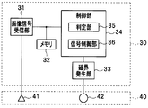
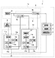
- 3 is a functional block diagram showing the main part of the extracorporeal device
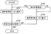
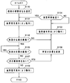
- FIG. 4 is a flowchart showing an operation mode control routine
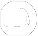
- FIG. 5 is a diagram schematically showing an example of an image captured on the stomach
- FIG. 6 is a duodenal bulb part.
- FIG. 7 is a diagram schematically showing an example of an image captured in the small intestine
- FIG. 8 is a flowchart showing a first modification of the operation mode control routine
- FIG. 9 is a flowchart showing a second modification of the operation mode control routine.
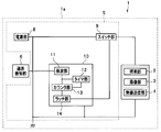
- a medical system 50 shown in FIG. 1 includes various information between a swallowable capsule endoscope 1 introduced into a body cavity of a subject 100 and the capsule endoscope 1 arranged outside the subject 100. And an extracorporeal device 30 for wireless communication.
- the capsule endoscope 1 captures image data by capturing an illumination unit 2 that emits illumination light for illuminating a subject in the body cavity of the subject 100, and a subject illuminated by the illumination unit.
- An imaging unit 3 to be acquired a wireless transmission unit 4 as an image signal transmission unit that modulates image data acquired by the imaging unit 3 into a wireless signal and transmits the signal to the outside, an illumination unit 2, an imaging unit 3, and a wireless transmission unit
- a power supply unit 5 capable of supplying driving power for driving the respective units 4
- a magnetic field detection unit 6 capable of detecting a magnetic field generated in the extracorporeal device 30 (for example, a plurality of burst AC magnetic fields),
- the image acquisition unit in the present embodiment includes, for example, the illumination unit 2 and the imaging unit 3.
- the power supply unit 5 includes a power supply unit 8 including a built-in battery that can supply power for driving each unit of the capsule endoscope 1, a switch unit 9, and a signal reception unit 10. Has been.
- the magnetic field detection unit 6 is configured by a resonance circuit including a coil and a capacitor, for example.
- the magnetic field detection unit 6 generates a magnetic field detection signal that is an electrical signal corresponding to a detection result (for example, a waveform at the time of detection) of the AC magnetic field generated from the extracorporeal device 30 and outputs the magnetic field detection signal to the signal reception unit 10.
- the power supply unit 8 is connected so as to constantly supply power to the signal receiving unit 10 and supply power to each of the illumination unit 2, the imaging unit 3, and the wireless transmission unit 4 via the switch unit 9.
- the switch unit 9 is connected between each unit of the illumination unit 2, the imaging unit 3, and the wireless transmission unit 4 and the power supply unit 8, and is turned on or off based on the output state of the switching signal from the signal reception unit 10. As a result, the power supply state from the power supply unit 8 to each unit of the illumination unit 2, the imaging unit 3, and the wireless transmission unit 4 can be switched between a conduction state and an open state.
- the signal receiving unit 10 detects a magnetic field detection signal having a signal level equal to or higher than a preset threshold and outputs a pulse signal, and a certain time has elapsed since the detection unit 11 started to output the pulse signal.
- the timer unit 12 that measures the time until the signal is received, the counter unit 13 that obtains a count value by counting the number of times the pulse signal is input from the detection unit 11 one by one, and the output signal from the counter unit 13 are input.
- a latch unit 14 that inverts the output of a switching signal for switching the on / off state of the switch unit 9 every time.
- the detection unit 11 is configured by, for example, a peak hold circuit including a diode, a capacitor, and a resistor. That is, the detection unit 11 is output from the magnetic field detection unit 6 when the output interval of the magnetic field detection signal output from the magnetic field detection unit 6 is equal to or greater than the time constant ⁇ determined by the product of the capacitance of the capacitor and the resistance value. The magnetic field detection signal is appropriately detected. And the detection part 11 can detect a magnetic field detection signal output from the magnetic field detection part 6 appropriately by detecting the magnetic field detection signal output from the extracorporeal apparatus 30 for every output interval more than time constant (tau). It is configured.
- a peak hold circuit including a diode, a capacitor, and a resistor. That is, the detection unit 11 is output from the magnetic field detection unit 6 when the output interval of the magnetic field detection signal output from the magnetic field detection unit 6 is equal to or greater than the time constant ⁇ determined by the product of the capacitance of the capacitor and the resistance value.
- the magnetic field detection signal is appropriately
- the detection unit 11 detects the magnetic field detection signal output from the magnetic field detection unit 6 at every output interval equal to or greater than the time constant ⁇ , thereby matching the number of output of the alternating magnetic field output from the extracorporeal device 30 in a burst shape.
- the number of pulse signals to be output can be continuously output to the counter unit 13.
- the timer unit 12 operates to reset the count value of the counter unit 13 to 0 when a certain time has elapsed.
- the counter unit 13 outputs an output signal to the latch unit 14 when detecting that the count value obtained by counting the number of input of the pulse signal from the detection unit 11 by one reaches the signal output count value. It is configured.
- the extracorporeal device 30 includes an image signal receiving unit 31, a memory 32, a magnetic field generation unit 33, and a control unit 34.
- the image signal receiving unit 31 receives the wireless signal transmitted from the wireless transmission unit 4 of the capsule endoscope 1 via the receiving antenna 41, and receives image data (endoscopic image data) from the received wireless signal. ).
- the memory 32 is configured by, for example, an external memory and stores the image data extracted by the image signal receiving unit 31.
- the magnetic field generator 33 has a configuration capable of generating a burst-like AC electric field for switching the power supply state in the capsule endoscope 1. Specifically, the magnetic field generation unit 33 generates a plurality of burst-like AC magnetic fields in response to an output instruction from the control unit 34, and is applied to the capsule endoscope 1 via the transmission antenna 42. To send.
- the control unit 34 includes a determination unit 35 and a signal control unit 36.
- the determination unit 35 determines whether or not the capsule endoscope 1 is in a predetermined digestive tract by analyzing the image.
- a pixel in which the luminance difference between adjacent pixels is equal to or greater than a predetermined value is detected as an edge.
- the most edges can be detected from the image of the small intestine where fine villi are present.
- almost no edge can be detected from the image of the substantially flat duodenal bulb.
- an edge having a predetermined length can be detected from an image of the stomach where a pleat of a predetermined length extends.
- the small intestine where fine villi are present has the largest luminance dispersion, followed by the stomach and the duodenal bulb.
- description is abbreviate
- the signal control unit 36 controls the image acquisition unit (the illumination unit 2 and the imaging unit 3) and the wireless transmission unit 4 to operate continuously or intermittently according to the determination result of the determination unit 35 (multiple bursts). (AC magnetic field) is controlled.
- the image acquisition unit and the wireless transmission unit 4 operate intermittently until the determination unit 35 determines that the capsule endoscope 1 has reached the small intestine.
- the control signal output control to the capsule endoscope 1 is performed so that the determination unit 35 determines that the capsule endoscope 1 has reached the small intestine
- the image acquisition unit and the wireless transmission unit 4 continuously
- the control output of the control signal to the capsule endoscope 1 is performed so as to operate.
- the receiving antenna 41 and the transmitting antenna 42 are disposed on a cover-type clothing (for example, a vest) 40 worn by the subject 100.
- a cover-type clothing for example, a vest
- This routine is executed, for example, when the capsule endoscope 1 is swallowed by the subject 100 and a switch (not shown) of the extracorporeal device 30 is turned on.
- the routine starts, first, in step S101, the control unit 34 generates a plurality of burst alternating magnetic fields through the magnetic field generation unit 33 so as to turn on the switch unit 9 of the capsule endoscope 1.
- the AC magnetic field is transmitted to the capsule endoscope 1 via the transmitting antenna 42 and received by the magnetic field detector 6 of the capsule endoscope 1. Then, the AC magnetic field received by the magnetic field detection unit 6 is converted into a magnetic field detection signal and then output to the signal reception unit 10.
- the signal receiving unit 10 turns on the switch unit 9, and power supply from the power supply unit 8 to the illumination unit 2, the imaging unit 3, and the wireless transmission unit 4 is started.
- the subject in the body cavity of the subject 100 is illuminated by the illuminating unit 2 and imaged by the imaging unit 3, and the image data of the imaged subject is modulated into a radio signal by the wireless transmission unit 4.
- a radio signal from the radio transmission unit 4 is received via the reception antenna 41.
- the received signal is demodulated into image data by the image signal receiving unit 31 of the extracorporeal device 30, and then stored in the memory 32 and appropriately input to the control unit 34.
- control unit 34 analyzes the latest image data input from the image signal receiving unit 31, and the currently acquired image is an image at a desired position in the digestive tract. Or not (for example, whether or not the image is a small intestine image).
- control unit 34 proceeds to step S103 to turn off the switch unit 9 of the capsule endoscope 1. Therefore, a plurality of burst-like AC signals are generated through the magnetic field generator 33.
- the AC magnetic field is transmitted to the capsule endoscope 1 via the transmitting antenna 42 and received by the magnetic field detector 6 of the capsule endoscope 1. Then, the AC magnetic field received by the magnetic field detection unit 6 is converted into a magnetic field detection signal and then output to the signal reception unit 10.
- the signal receiving unit 10 turns off the switch unit 9, and power supply from the power supply unit 8 to the illumination unit 2, the imaging unit 3, and the wireless transmission unit 4 is stopped.
- step S104 the control unit 34 checks whether or not the set time T has elapsed from the OFF operation of the switch unit 9. If it is determined that the set time T has not yet elapsed, the control unit 34 continues. stand by.
- step S104 when it is determined in step S104 that the set time T has elapsed from the off operation of the switch unit 9, the control unit 34 returns to step S101.
- step S101 to step S104 in the control unit 34 by performing a series of processes from step S101 to step S104 in the control unit 34, in the capsule endoscope 1, the illumination unit 2, the imaging unit 3, and the wireless transmission unit 4 are set for a set time. It is intermittently operated every T (that is, the capsule endoscope 1 is operated in the intermittent operation mode).
- step S102 If it is determined in step S102 that the currently acquired image is an image at a desired position as a result of the image analysis, the control unit 34 does not change the state of the capsule endoscope 1 as it is (that is, in step S101). The routine is exited while the switch section 9 is kept on.
- the operation mode control routine is completed while the switch unit 9 is turned on in this way, in the capsule endoscope 1, the illumination unit 2, the imaging unit 3, and the wireless transmission unit 4 are continuously connected. Operated (ie, the capsule endoscope is operated in the continuous operation mode).
- the capsule endoscope 1 is in the predetermined digestive tract by analyzing the image transmitted from the capsule endoscope 1 to the extracorporeal device 30 arranged outside the subject 100.
- the signal control unit 36 that performs output control of a control signal for operation, it is possible to suppress consumption of the power supply unit 8 of the capsule endoscope 1 without imposing a burden on the observer and Images can be obtained.
- the patient (subject 100) can move around freely.
- step S102 If it is determined in step S102 that the currently acquired image is an image at a desired position as a result of the image analysis, the control unit 34 proceeds to step S105.
- step S105 the control unit 34 performs an analysis process on the latest image data input from the image signal receiving unit 31 by an analysis process similar to that in step S102 described above, and the currently acquired image is stored in the digestive tract. It is determined whether the image is at a desired position (for example, whether the image is a small intestine image).
- step S105 when it is determined as a result of image analysis that the currently acquired image is an image at a desired position, the control unit 34 stands by and analyzes each time the latest image data is input. Repeat the process.
- step S105 if it is determined in step S105 that the currently acquired image is no longer the image at the desired position as a result of the image analysis, the control unit 34 proceeds to step S106, and the switch unit 9 of the capsule endoscope 1 is performed. In order to turn off the signal, a burst AC signal is generated a plurality of times through the magnetic field generator 33, and then the routine is exited.
- the control unit 34 selects the first observation site as a desired position prior to the processing in step S101. That is, for example, in the present modification in which images of the stomach and small intestine are acquired, the stomach is selected as a desired position.
- step S105 of this routine as a result of the image analysis, it is determined that the currently earned image is no longer the image at the desired position (in this variation, the currently selected stomach or small intestine image).
- the control unit 34 proceeds to step S107 and checks whether there is a next observation site as a desired observation site. That is, for example, in the present modification in which images of the stomach and the small intestine are acquired, it is checked whether or not the small intestine has not yet been selected as the desired position.
- step S107 If it is determined in step S107 that there is a next observation site, the control unit 34 proceeds to step S108, and after changing the desired position to the next observation site (for example, changing the desired position from the stomach to the small intestine). After changing to), the process returns to step S103.
- step S107 determines whether there is no next observation site. If it is determined in step S107 that there is no next observation site, the control unit 34 proceeds to step S109 and performs a plurality of operations through the magnetic field generation unit 33 to turn off the switch unit 9 of the capsule endoscope 1. After generating a burst of alternating current signals, the routine is exited.
- FIG. 10 relates to the second embodiment of the present invention
- FIG. 10 is a functional block diagram showing the main part of the capsule endoscope.
- the switch unit 9 includes two switch units 9a and 9b
- the signal reception unit 10 includes two signal reception units 10a and 10b. It differs mainly from the embodiment.
- symbol is attached
- the switch unit 9a is connected to the power supply unit 8, and is turned on or off based on the output state of the switching signal from the signal receiving unit 10a having the function as the first switching control unit. As a result, the power supply state from the power supply unit 8 to the signal receiving unit 10b can be switched to a conductive state or an open state.
- the switch unit 9b is connected between each unit of the illumination unit 2, the imaging unit 3, and the wireless transmission unit 4 and the power supply unit 8, and from the signal reception unit 10b having a function as a second switching control unit.
- the power supply state from the power supply unit 8 to each unit of the illumination unit 2, the imaging unit 3, and the wireless transmission unit 4 is switched to a conductive state or an open state by being turned on or off based on the output state of the switching signal. It is configured to be able to.
- the signal receiving unit 10a detects a magnetic field detection signal having a signal level equal to or higher than a threshold TH1 and outputs a pulse signal, and until a certain time TA1 has elapsed since the detection unit 11a started to output a pulse signal.
- a timer unit 12a that measures time
- a counter unit 13a that obtains a count value by counting the number of times a pulse signal is input from the detection unit 11a, and a switch each time an output signal is input from the counter unit 13a
- a latch unit 14a for inverting the output of a switching signal for switching the on / off state of the unit 9a.
- the detection unit 11a is configured by a peak hold circuit including, for example, a diode, a capacitor, and a resistor. That is, when the output interval of the magnetic field detection signal output from the magnetic field detection unit 6 is not less than the time constant ⁇ 1 determined by the product of the capacitance of the capacitor and the resistance value of the resistor, the detection unit 11a An output magnetic field detection signal can be appropriately detected.
- the detection part 11a detects the magnetic field detection signal output from the magnetic field detection part 6 for every output space
- the number of pulse signals corresponding to the number of magnetic field detection signals output from the magnetic field detection unit 6) can be continuously output to the counter unit 13a.
- the timer unit 12a operates to reset the count value of the counter unit 13a to 0 when a certain time TA1 has elapsed.
- the timer unit 12a of the present embodiment is not limited to measuring time until a certain time TA1 elapses after the detection unit 11a starts outputting a pulse signal.
- the pulse signal output from the detection unit 11a The time corresponding to the output interval may be measured, or the two times may be measured simultaneously.
- the timer unit 12a is configured to measure a time corresponding to the output interval of the pulse signal output from the detection unit 11a, the time constant ⁇ 1 and the measurement time of the timer unit 12a are You may make it substantially correspond.
- the counter unit 13a outputs an output signal to the latch unit 14a when detecting that the count value obtained by counting the number of input of the pulse signal from the detection unit 11a by one reaches the signal output count value PA. It is configured as follows.
- the signal receiving unit 10b amplifies the signal level of the magnetic field detection signal output from the magnetic field detection unit 6 to a signal level equal to or higher than the threshold value TH2, and the magnetic field detection signal having a signal level equal to or higher than the threshold value TH2.
- a detection unit 11b that detects and outputs a pulse signal, a timer unit 12b that measures time from when the detection unit 11b starts outputting a pulse signal until a predetermined time TA2 elapses, and an input of the pulse signal from the detection unit 11b
- a counter unit 13b that obtains a count value by counting the number of times one by one
- a latch unit 14b that inverts the output of a switching signal for switching the on / off state of the switch unit 9b every time an output signal from the counter unit 13b is input. And is configured.
- the signal receiving unit 10b of the present embodiment includes the amplifying unit 21, the detection sensitivity of the alternating magnetic field (control signal) generated by the magnetic field generating unit 33 is relatively higher than that of the signal receiving unit 10a. It is set to be.
- the detection unit 11b is configured by a peak hold circuit including, for example, a diode, a capacitor, and a resistor.
- the detection unit 11b receives the magnetic field detection signal from the magnetic field detection unit 6 when the output interval of the magnetic field detection signal output from the magnetic field detection unit 6 is not less than the time constant ⁇ 2 determined by the product of the capacitance of the capacitor and the resistance value of the resistor. An output magnetic field detection signal can be appropriately detected.
- the detection part 11a detects the magnetic field detection signal output from the magnetic field detection part 6 for every output space
- the number of pulse signals corresponding to the number of magnetic field detection signals output from the magnetic field detection unit 6) can be continuously output to the counter unit 13b.
- the timer unit 12b operates to reset the count value of the counter unit 13b to 0 when the predetermined time TA2 has elapsed.
- the timer unit 12b is not limited to measuring the time from when the detection unit 11b starts outputting a pulse signal until a predetermined time TA2 elapses.
- the timer unit 12b outputs a pulse signal output from the detection unit 11b.
- the time corresponding to the output interval may be measured, or the two times may be measured simultaneously.
- the timer unit 12b is configured to measure a time corresponding to the output interval of the pulse signal output from the detection unit 11b, the time constant ⁇ 2 and the measurement time of the timer unit 12b are You may make it correspond.
- the predetermined times TA1 and TA2 may be set to the same time, or may be set to satisfy TA1> TA2.
- the counter unit 13b When the counter unit 13b detects that the count value obtained by counting the number of input of the pulse signal from the detection unit 11b by one reaches the signal output count value PB, the counter unit 13b outputs the output signal to the latch unit 14b. It is configured as follows.
- the signal output count values PA and PB described above may be set to arbitrary values as long as they have a relationship of PA> PB.
- the capacitance of each capacitor and the resistance value of each resistor are set so that the time constant ⁇ 1 of the detection unit 11a and the time constant ⁇ 2 of the detection unit 11b have the same value. It is assumed that
- the switch unit 9a is turned on before being swallowed into the subject 100, and the on operation or the off operation due to the generation of the magnetic field signal in the above steps S101, S103, S106, and S109 This is performed for the unit 9b.
- a magnetic field for turning on / off the switch unit 9 a can be generated by the magnetic field generation unit 33 of the extracorporeal device 30.
- the magnetic field for turning on / off the switch unit 9 a may be generated by a magnetic field generation unit provided separately from the magnetic field generation unit 33.
- the same operational effects as those of the first embodiment described above can be achieved.
- the amplification of the amplification unit 21 does not cause an increase in the size of the magnetic field detection unit 6 or the like.
- the power supply state from the power supply unit 8 to the illumination unit 2, the imaging unit 3, and the wireless transmission unit 4 can be accurately switched between a conduction state and an open state. In this case, since the power from the power supply unit 8 is not supplied to the amplification unit 21 while the switch unit 9a is turned off, unnecessary power consumption can be accurately suppressed.
Abstract
According to the present invention, providing an extracorporeal device (30) arranged outside the body of a subject (100) with: a determination unit (35) for determining whether or not a capsule endoscope (1) is in a predetermined digestive tract according to analysis of an image transmitted from the capsule endoscope (1); and a signal control unit (36) for controlling the output of a control signal for continuously operating or intermittently operating the image acquisition unit (illumination unit (2) and imaging unit (3)) and wireless transmission unit (4) of the capsule endoscope (1), in accordance with the determination result of the determination unit (35); makes it possible to minimize depletion of the power source unit (8) of the capsule endoscope (1) without imposing a burden on the observer, and to obtain a desired image.
Description
本発明は、カプセル型内視鏡を用いて生体内の画像情報を取得可能な医療システムに関する。
The present invention relates to a medical system capable of acquiring in-vivo image information using a capsule endoscope.
医療分野における内視鏡は、生体内の観察等の用途において従来用いられている。この内視鏡の1つとして、被験者が嚥下することにより体腔内に配置され、蠕動運動に伴って体腔内を移動しつつ被写体の像を撮像し、撮像した被写体の像を撮像信号として外部に無線伝送可能なカプセル型内視鏡が近年提案されている。
Endoscopes in the medical field are conventionally used in applications such as in vivo observation. As one of the endoscopes, a subject is placed in a body cavity by swallowing, and an image of a subject is captured while moving in the body cavity with a peristaltic motion, and the captured subject image is externally captured as an imaging signal. In recent years, capsule endoscopes capable of wireless transmission have been proposed.
この種のカプセル型内視鏡として、例えば、日本国特開2009-89907号公報には、カプセル型内視鏡の外部から交流磁界を照射することにより、該カプセル型内視鏡の起動及び停止に係る切り替えを行うことが可能な構成が開示されている。すなわち、日本国特開2009-89907号公報に開示された生態観察システムは、生体内に配置可能な寸法及び形状等を有して構成されるカプセル型内視鏡と、カプセル型内視鏡の外部において交流磁界を発生させる磁界発生部と、を具備している。磁界発生部は、例えば、ユーザによるスイッチ操作等に応じて、磁界の発生状態をオンまたはオフの何れかに切り替えることが可能な構成を有している。一方、カプセル型内視鏡は、生体内の被写体を照射するための照明光を発する照明部と、照明部により照明された被写体を撮像し、撮像信号として出力する撮像部と、撮像部から出力された撮像信号を無線により生体外へ伝送する無線伝送部と、照明部、撮像部及び無線伝送部の各部の駆動に要する駆動電力を供給する電力供給部と、磁界発生部において発せられた交流磁界を検知可能な磁界検知部と、を内部に有している。そして、上記構成により、磁界発生部において発せられた交流磁界を検知する度に電力のオン/オフ切り替えが可能となっている。
As this type of capsule endoscope, for example, Japanese Patent Application Laid-Open No. 2009-89907 discloses activation and stop of the capsule endoscope by irradiating an alternating magnetic field from the outside of the capsule endoscope. The structure which can perform the change which concerns on is disclosed. That is, an ecological observation system disclosed in Japanese Patent Application Laid-Open No. 2009-89907 includes a capsule endoscope configured to have a size and shape that can be placed in a living body, and a capsule endoscope. And a magnetic field generation unit that generates an alternating magnetic field outside. The magnetic field generation unit has a configuration capable of switching the magnetic field generation state to either on or off in accordance with, for example, a switch operation by the user. On the other hand, a capsule endoscope is an illumination unit that emits illumination light for illuminating a subject in a living body, an imaging unit that captures an image of a subject illuminated by the illumination unit, and outputs the imaging signal, and an output from the imaging unit A wireless transmission unit that wirelessly transmits the captured imaging signal to the outside of the living body, a power supply unit that supplies driving power required for driving each unit of the illumination unit, the imaging unit, and the wireless transmission unit, and an alternating current generated in the magnetic field generation unit A magnetic field detection unit capable of detecting the magnetic field. With the above configuration, the power can be switched on / off each time an AC magnetic field generated in the magnetic field generator is detected.
さらに、日本国特開2009-89907号公報には、内蔵バッテリの消耗を抑制すること等を目的として、被験者の体内にカプセル型内視鏡を配置した後、磁界発生部から発せられる交流磁界により電源のオン/オフを適宜切り替える技術が開示されている。具体的には、例えば、観察等が必要ない部位を通過している際には、電源をオフしておき、所望の観察部位に到達した際に、磁界発生部から交流磁界を発生させることによりカプセル型内視鏡の電源をオンするような制御が可能である。さらに、観察等が必要ない部位に到達した場合は、再度磁界発生部から交流磁界を発生することで、カプセル型内視鏡の電源をオフすることが可能である。
Furthermore, Japanese Patent Application Laid-Open No. 2009-89907 discloses an alternating magnetic field generated from a magnetic field generator after a capsule endoscope is placed in the body of a subject for the purpose of suppressing the consumption of the internal battery. A technique for appropriately switching on / off a power supply is disclosed. Specifically, for example, when passing through a site where observation or the like is not necessary, the power is turned off, and when the desired observation site is reached, an alternating magnetic field is generated from the magnetic field generator. Control to turn on the power of the capsule endoscope is possible. Furthermore, when a part that does not require observation or the like is reached, the capsule endoscope can be powered off by generating an alternating magnetic field again from the magnetic field generator.
しかしながら、上述の日本国特開2009-89907号公報に開示されているように、体内のカプセル型内視鏡が、所望の部位に到達した場合に電源をオンする、或いは、所望の部位を通過した場合に電源をオフするためには、カプセル型内視鏡が体内を移動している間、観察者である医師や医療技師が直接モニタを観察する必要があり、観察者の大きな負担となる虞がある。
However, as disclosed in the above Japanese Patent Application Laid-Open No. 2009-89907, when the capsule endoscope in the body reaches a desired site, the power is turned on, or the desired site passes. In order to turn off the power in this case, it is necessary for the doctor or medical technician who is an observer to observe the monitor directly while the capsule endoscope is moving inside the body, which is a heavy burden on the observer. There is a fear.
本発明は上記事情に鑑みてなされたもので、観察者に負担強いることなく、電源の消耗を抑制するとともに、所望の画像を得ることができる医療システムを提供することを目的とする。
The present invention has been made in view of the above circumstances, and an object of the present invention is to provide a medical system that can suppress consumption of a power source and can obtain a desired image without burdening an observer.
本発明の一態様による医療システムは、画像を取得する画像取得部と、前記画像を無線送信する画像信号送信部と、前記画像取得部及び前記画像信号送信部に対して電力を供給可能な電源部と、外部から送信される制御信号を受信する制御信号受信部と、前記制御信号に応じて前記電源部から前記画像取得部及び前記画像信号送信部への電力供給のオンオフ状態を切り替えるスイッチ部と、を有し、被験者に嚥下されるカプセル型内視鏡と、前記画像信号を受信する画像信号受信部と、前記画像の解析によって前記カプセル型内視鏡が所定の消化管内にあるか否かを判定する判定部と、前記判定部の判定結果に応じて、前記画像取得部及び前記画像信号送信部を連続動作或いは間欠動作させるための前記制御信号の出力制御を行う信号制御部と、を有し、前記被験者の体外に配置される体外装置と、を具備するものである。
A medical system according to an aspect of the present invention includes an image acquisition unit that acquires an image, an image signal transmission unit that wirelessly transmits the image, and a power source that can supply power to the image acquisition unit and the image signal transmission unit A control signal receiving unit that receives a control signal transmitted from the outside, and a switch unit that switches an on / off state of power supply from the power supply unit to the image acquisition unit and the image signal transmission unit according to the control signal A capsule endoscope that is swallowed by a subject, an image signal receiving unit that receives the image signal, and whether the capsule endoscope is in a predetermined digestive tract by analysis of the image And a signal control for performing output control of the control signal for causing the image acquisition unit and the image signal transmission unit to operate continuously or intermittently according to a determination result of the determination unit. When have is for anda extracorporeal device disposed outside the body of the subject.
以下、図面を参照して本発明の形態を説明する。図1乃至図9は本発明の第1の実施形態に係わり、図1は被験者に対して使用される医療システムの概略構成図、図2はカプセル型内視鏡の要部を示す機能ブロック図、図3は体外装置の要部を示す機能ブロック図、図4は動作モード制御ルーチンを示すフローチャート、図5は胃で撮像される画像の一例を模式的に示す図、図6は十二指腸球部で撮像される画像の一例を模式的に示す図、図7は小腸で撮像される画像の一例を模式的に示す図、図8は動作モード制御ルーチンの第1変形例を示すフローチャート、図9は動作モード制御ルーチンの第2変形例を示すフローチャートである。
Hereinafter, embodiments of the present invention will be described with reference to the drawings. 1 to 9 relate to a first embodiment of the present invention, FIG. 1 is a schematic configuration diagram of a medical system used for a subject, and FIG. 2 is a functional block diagram showing a main part of a capsule endoscope. 3 is a functional block diagram showing the main part of the extracorporeal device, FIG. 4 is a flowchart showing an operation mode control routine, FIG. 5 is a diagram schematically showing an example of an image captured on the stomach, and FIG. 6 is a duodenal bulb part. FIG. 7 is a diagram schematically showing an example of an image captured in the small intestine, FIG. 8 is a flowchart showing a first modification of the operation mode control routine, and FIG. FIG. 9 is a flowchart showing a second modification of the operation mode control routine.
図1に示す医療システム50は、被験者100の体腔内に導入される飲み込み型のカプセル型内視鏡1と、被験者100の外部に配置されてカプセル型内視鏡1との間で各種の情報を無線通信する体外装置30と、を備えている。
A medical system 50 shown in FIG. 1 includes various information between a swallowable capsule endoscope 1 introduced into a body cavity of a subject 100 and the capsule endoscope 1 arranged outside the subject 100. And an extracorporeal device 30 for wireless communication.
図2に示すように、カプセル型内視鏡1は、被験者100の体腔内の被写体を照明するための照明光を発する照明部2と、照明部により照明された被写体を撮像して画像データを取得する撮像部3と、撮像部3により取得された画像データを無線信号に変調して外部へ送信する画像信号送信部としての無線送信部4と、照明部2、撮像部3及び無線送信部4の各部を駆動させるための駆動電力を供給可能な電力供給部5と、体外装置30において発せられた磁界(例えば、複数回のバースト状の交流磁界)を検知可能な磁界検知部6と、を筐体1aの内部に有している。すなわち、本実施形態における画像取得部は、例えば、照明部2と撮像部3とを具備して構成されている。
As shown in FIG. 2, the capsule endoscope 1 captures image data by capturing an illumination unit 2 that emits illumination light for illuminating a subject in the body cavity of the subject 100, and a subject illuminated by the illumination unit. An imaging unit 3 to be acquired, a wireless transmission unit 4 as an image signal transmission unit that modulates image data acquired by the imaging unit 3 into a wireless signal and transmits the signal to the outside, an illumination unit 2, an imaging unit 3, and a wireless transmission unit A power supply unit 5 capable of supplying driving power for driving the respective units 4, a magnetic field detection unit 6 capable of detecting a magnetic field generated in the extracorporeal device 30 (for example, a plurality of burst AC magnetic fields), In the housing 1a. That is, the image acquisition unit in the present embodiment includes, for example, the illumination unit 2 and the imaging unit 3.
電力供給部5は、カプセル型内視鏡1の各部を駆動させるための電力を供給可能な内蔵バッテリ等からなる電源部8と、スイッチ部9と、信号受信部10と、を有して構成されている。
The power supply unit 5 includes a power supply unit 8 including a built-in battery that can supply power for driving each unit of the capsule endoscope 1, a switch unit 9, and a signal reception unit 10. Has been.
磁界検知部6は、例えば、コイル及びコンデンサからなる共振回路によって構成されている。この磁界検知部6は、体外装置30から発せられた交流磁界の検知結果(例えば、検知時の波形等)に応じた電気信号である磁界検知信号を生成して信号受信部10へ出力する。
The magnetic field detection unit 6 is configured by a resonance circuit including a coil and a capacitor, for example. The magnetic field detection unit 6 generates a magnetic field detection signal that is an electrical signal corresponding to a detection result (for example, a waveform at the time of detection) of the AC magnetic field generated from the extracorporeal device 30 and outputs the magnetic field detection signal to the signal reception unit 10.
電源部8は、信号受信部10へ常時電力を供給し、スイッチ部9を介して照明部2、撮像部3及び無線送信部4の各部へ電力を供給するように接続されている。
The power supply unit 8 is connected so as to constantly supply power to the signal receiving unit 10 and supply power to each of the illumination unit 2, the imaging unit 3, and the wireless transmission unit 4 via the switch unit 9.
スイッチ部9は、照明部2、撮像部3及び無線送信部4の各部と、電源部8との間に接続されており、信号受信部10からの切替信号の出力状態に基づいてオンまたはオフされることにより、電源部8から照明部2、撮像部3及び無線送信部4の各部への電力の供給状態を導通状態または開放状態に切り替えることができるよう構成されている。
The switch unit 9 is connected between each unit of the illumination unit 2, the imaging unit 3, and the wireless transmission unit 4 and the power supply unit 8, and is turned on or off based on the output state of the switching signal from the signal reception unit 10. As a result, the power supply state from the power supply unit 8 to each unit of the illumination unit 2, the imaging unit 3, and the wireless transmission unit 4 can be switched between a conduction state and an open state.
信号受信部10は、予め設定された閾値以上の信号レベルを具備する磁界検知信号を検波してパルス信号を出力する検波部11と、検波部11がパルス信号を出力し始めてから一定時間が経過するまでの時間の計測を行うタイマ部12と、検波部11からのパルス信号の入力回数を1ずつカウントすることによりカウント値を得るカウンタ部13と、カウンタ部13からの出力信号が入力される毎にスイッチ部9のオンオフ状態を切り替えるための切替信号の出力を反転するラッチ部14と、を有して構成されている。
The signal receiving unit 10 detects a magnetic field detection signal having a signal level equal to or higher than a preset threshold and outputs a pulse signal, and a certain time has elapsed since the detection unit 11 started to output the pulse signal. The timer unit 12 that measures the time until the signal is received, the counter unit 13 that obtains a count value by counting the number of times the pulse signal is input from the detection unit 11 one by one, and the output signal from the counter unit 13 are input. And a latch unit 14 that inverts the output of a switching signal for switching the on / off state of the switch unit 9 every time.
検波部11は、例えば、ダイオードと、コンデンサと、抵抗と、からなるピークホールド回路によって構成されている。すなわち、検波部11は、磁界検知部6から出力される磁界検知信号の出力間隔がコンデンサの容量と抵抗値との積により定められる時定数τ以上である場合において、磁界検知部6から出力される磁界検知信号を適切に検波できるように構成されている。そして、検波部11は、時定数τ以上の出力間隔毎に体外装置30から出力される磁界検知信号を検波することにより、磁界検知部6から出力される磁界検知信号を適切に検波できるように構成されている。そして、検波部11は、時定数τ以上の出力間隔毎に磁界検知部6から出力される磁界検知信号を検波することにより、体外装置30からバースト状に出力される交流磁界の出力回数に一致する数のパルス信号をカウンタ部13へ連続的に出力することができるように構成されている。
The detection unit 11 is configured by, for example, a peak hold circuit including a diode, a capacitor, and a resistor. That is, the detection unit 11 is output from the magnetic field detection unit 6 when the output interval of the magnetic field detection signal output from the magnetic field detection unit 6 is equal to or greater than the time constant τ determined by the product of the capacitance of the capacitor and the resistance value. The magnetic field detection signal is appropriately detected. And the detection part 11 can detect a magnetic field detection signal output from the magnetic field detection part 6 appropriately by detecting the magnetic field detection signal output from the extracorporeal apparatus 30 for every output interval more than time constant (tau). It is configured. Then, the detection unit 11 detects the magnetic field detection signal output from the magnetic field detection unit 6 at every output interval equal to or greater than the time constant τ, thereby matching the number of output of the alternating magnetic field output from the extracorporeal device 30 in a burst shape. The number of pulse signals to be output can be continuously output to the counter unit 13.
タイマ部12は、一定時間が経過した際に、カウンタ部13のカウント値を0にリセットさせるよう動作する。
The timer unit 12 operates to reset the count value of the counter unit 13 to 0 when a certain time has elapsed.
カウンタ部13は、検波部11からのパルス信号の入力回数を1ずつカウントして得たカウント値が信号出力カウント値に達したことを検出した際に、出力信号をラッチ部14へ出力するように構成されている。
The counter unit 13 outputs an output signal to the latch unit 14 when detecting that the count value obtained by counting the number of input of the pulse signal from the detection unit 11 by one reaches the signal output count value. It is configured.
図3に示すように、体外装置30は、画像信号受信部31と、メモリ32と、磁界発生部33と、制御部34と、を有して構成されている。
As shown in FIG. 3, the extracorporeal device 30 includes an image signal receiving unit 31, a memory 32, a magnetic field generation unit 33, and a control unit 34.
画像信号受信部31は、カプセル型内視鏡1の無線送信部4から送信された無線信号を、受信用アンテナ41を介して受信し、受信した無線信号中から画像データ(内視鏡画像データ)を抽出する。
The image signal receiving unit 31 receives the wireless signal transmitted from the wireless transmission unit 4 of the capsule endoscope 1 via the receiving antenna 41, and receives image data (endoscopic image data) from the received wireless signal. ).
メモリ32は、例えば、外部メモリ等によって構成され、画像信号受信部31で抽出された画像データを記憶する。
The memory 32 is configured by, for example, an external memory and stores the image data extracted by the image signal receiving unit 31.
磁界発生部33は、カプセル型内視鏡1における電源状態を切り替えるためのバースト状の交流電界を発生することが可能な構成を有している。具体的には、磁界発生部33は、制御部34からの出力指示に応じて、複数回のバースト状の交流磁界を発生させ、送信用アンテナ42を介して、カプセル型内視鏡1に対して送信する。
The magnetic field generator 33 has a configuration capable of generating a burst-like AC electric field for switching the power supply state in the capsule endoscope 1. Specifically, the magnetic field generation unit 33 generates a plurality of burst-like AC magnetic fields in response to an output instruction from the control unit 34, and is applied to the capsule endoscope 1 via the transmission antenna 42. To send.
制御部34は、判定部35と、信号制御部36と、を有して構成されている。
The control unit 34 includes a determination unit 35 and a signal control unit 36.
判定部35は、画像の解析によってカプセル型内視鏡1が所定の消化管内にあるか否かを判定する。ここで、例えば、図5~7に示すように、胃と、十二指腸球部と、小腸と、の各画像の比較において、隣接する画素との輝度差が所定以上となる画素をエッジとして検出した場合、微細な絨毛が存在する小腸の画像からは最も多くエッジを検出することができる。これに対し、略平坦な十二指腸球部の画像からはほとんどエッジを検出することができない。また、所定の長さのヒダが延在する胃の画像からは所定の長さ連続するエッジを検出することができる。また、例えば、画像上に設定した所定領域の輝度の分散について解析すると、微細な絨毛が存在する小腸が最も輝度の分散が大きく、次いで、胃、十二指腸球部の順となる。例えば、これらを予めデータベース化した情報を基に、画像解析を行うことにより、胃から十二指腸への移動、十二指腸から小腸への移動を判定することが可能となる。その他、説明を省略するが、他の消化管についても、画像上に現出する種々の特徴から判別することが可能である。
The determination unit 35 determines whether or not the capsule endoscope 1 is in a predetermined digestive tract by analyzing the image. Here, for example, as shown in FIGS. 5 to 7, in the comparison of each image of the stomach, the duodenal bulb, and the small intestine, a pixel in which the luminance difference between adjacent pixels is equal to or greater than a predetermined value is detected as an edge. In this case, the most edges can be detected from the image of the small intestine where fine villi are present. In contrast, almost no edge can be detected from the image of the substantially flat duodenal bulb. Further, an edge having a predetermined length can be detected from an image of the stomach where a pleat of a predetermined length extends. Further, for example, when analyzing the luminance dispersion of a predetermined region set on the image, the small intestine where fine villi are present has the largest luminance dispersion, followed by the stomach and the duodenal bulb. For example, it is possible to determine the movement from the stomach to the duodenum and the movement from the duodenum to the small intestine by performing an image analysis based on information stored in a database in advance. In addition, although description is abbreviate | omitted, it can discriminate | determine from the various characteristics which appear on an image also about another digestive tract.
信号制御部36は、判定部35の判定結果に応じて、画像取得部(照明部2及び撮像部3)及び無線送信部4を連続動作或いは間欠動作させるための制御信号(複数回のバースト状の交流磁界)の出力制御を行う。例えば、検査対象として小腸が設定されている場合、判定部35においてカプセル型内視鏡1が小腸に達したと判定されるまでの間は、画像取得部及び無線送信部4が間欠的に動作するようカプセル型内視鏡1に対する制御信号の出力制御を行い、判定部35においてカプセル型内視鏡1が小腸に達したと判定された後は、画像取得部及び無線送信部4が連続的に動作するようカプセル型内視鏡1に対する制御信号の出力制御を行う。
The signal control unit 36 controls the image acquisition unit (the illumination unit 2 and the imaging unit 3) and the wireless transmission unit 4 to operate continuously or intermittently according to the determination result of the determination unit 35 (multiple bursts). (AC magnetic field) is controlled. For example, when the small intestine is set as an examination target, the image acquisition unit and the wireless transmission unit 4 operate intermittently until the determination unit 35 determines that the capsule endoscope 1 has reached the small intestine. After the control signal output control to the capsule endoscope 1 is performed so that the determination unit 35 determines that the capsule endoscope 1 has reached the small intestine, the image acquisition unit and the wireless transmission unit 4 continuously The control output of the control signal to the capsule endoscope 1 is performed so as to operate.
ここで、例えば、図1及び図2に示すように、受信用アンテナ41及び送信用アンテナ42は、被験体100が着用する被り型の衣類(例えば、ベスト)40に配設されている。
Here, for example, as shown in FIG. 1 and FIG. 2, the receiving antenna 41 and the transmitting antenna 42 are disposed on a cover-type clothing (for example, a vest) 40 worn by the subject 100.
次に、体外装置30の制御部34において実行されるカプセル型内視鏡1に対する動作モード制御について、図4に示す動作モード制御ルーチンのフローチャートに従って説明する。なお、以下においては、例えば、検査対象(所望の位置)として小腸が設定されている場合の制御について説明する。
Next, the operation mode control for the capsule endoscope 1 executed by the control unit 34 of the extracorporeal device 30 will be described according to the flowchart of the operation mode control routine shown in FIG. In the following, for example, control when the small intestine is set as the inspection target (desired position) will be described.
このルーチンは、例えば、カプセル型内視鏡1が被験者100によって嚥下され、且つ、体外装置30の図示しないスイッチがオン操作されることにより実行されるものである。ルーチンがスタートすると、制御部34は、先ず、ステップS101において、カプセル型内視鏡1のスイッチ部9をオン動作させるべく、磁界発生部33を通じて複数回のバースト状の交流磁界を発生させる。
This routine is executed, for example, when the capsule endoscope 1 is swallowed by the subject 100 and a switch (not shown) of the extracorporeal device 30 is turned on. When the routine starts, first, in step S101, the control unit 34 generates a plurality of burst alternating magnetic fields through the magnetic field generation unit 33 so as to turn on the switch unit 9 of the capsule endoscope 1.
この交流磁界は、送信用アンテナ42を介してカプセル型内視鏡1に送信され、カプセル型内視鏡1の磁界検知部6において受信される。そして、磁界検知部6において受信された交流磁界は、磁界検知信号へと変換された後、信号受信部10へと出力される。磁界検知信号が入力されると、信号受信部10はスイッチ部9をオン動作させ、電源部8から、照明部2、撮像部3、及び、無線送信部4への給電が開始される。これにより、被験者100の体腔内の被写体が照明部2によって照明されるとともに、撮像部3によって撮像され、撮像された被写体の画像データが、無線送信部4によって無線信号に変調され、体外装置30へと送信される。無線送信部4からの無線信号は、受信用アンテナ41を介して受信される。この受信信号は、体外装置30の画像信号受信部31において画像データに復調された後、メモリ32に記憶されるとともに、制御部34に適宜入力される。
The AC magnetic field is transmitted to the capsule endoscope 1 via the transmitting antenna 42 and received by the magnetic field detector 6 of the capsule endoscope 1. Then, the AC magnetic field received by the magnetic field detection unit 6 is converted into a magnetic field detection signal and then output to the signal reception unit 10. When the magnetic field detection signal is input, the signal receiving unit 10 turns on the switch unit 9, and power supply from the power supply unit 8 to the illumination unit 2, the imaging unit 3, and the wireless transmission unit 4 is started. As a result, the subject in the body cavity of the subject 100 is illuminated by the illuminating unit 2 and imaged by the imaging unit 3, and the image data of the imaged subject is modulated into a radio signal by the wireless transmission unit 4. Sent to. A radio signal from the radio transmission unit 4 is received via the reception antenna 41. The received signal is demodulated into image data by the image signal receiving unit 31 of the extracorporeal device 30, and then stored in the memory 32 and appropriately input to the control unit 34.
ステップS101からステップS102に進むと、制御部34は、画像信号受信部31から入力された最新の画像データの解析処理を行い、現在取得されている画像が消化管内の所望の位置の画像であるか否か(例えば、小腸の画像であるか否か)の判定を行う。
When the process proceeds from step S101 to step S102, the control unit 34 analyzes the latest image data input from the image signal receiving unit 31, and the currently acquired image is an image at a desired position in the digestive tract. Or not (for example, whether or not the image is a small intestine image).
そして、画像解析の結果、現在取得されている画像が所望の位置の画像ではないと判定した場合、制御部34は、ステップS103に進み、カプセル型内視鏡1のスイッチ部9をオフ動作させるべく、磁界発生部33を通じて複数回のバースト状の交流信号を発生させる。
If it is determined as a result of image analysis that the currently acquired image is not an image at a desired position, the control unit 34 proceeds to step S103 to turn off the switch unit 9 of the capsule endoscope 1. Therefore, a plurality of burst-like AC signals are generated through the magnetic field generator 33.
この交流磁界は、送信用アンテナ42を介してカプセル型内視鏡1に送信され、カプセル型内視鏡1の磁界検知部6において受信される。そして、磁界検知部6において受信された交流磁界は、磁界検知信号へと変換された後、信号受信部10へと出力される。磁界検知信号が入力されると、信号受信部10はスイッチ部9をオフ動作させ、電源部8から、照明部2、撮像部3、及び、無線送信部4への給電が停止される。
The AC magnetic field is transmitted to the capsule endoscope 1 via the transmitting antenna 42 and received by the magnetic field detector 6 of the capsule endoscope 1. Then, the AC magnetic field received by the magnetic field detection unit 6 is converted into a magnetic field detection signal and then output to the signal reception unit 10. When the magnetic field detection signal is input, the signal receiving unit 10 turns off the switch unit 9, and power supply from the power supply unit 8 to the illumination unit 2, the imaging unit 3, and the wireless transmission unit 4 is stopped.
ステップS103からステップS104に進むと、制御部34は、スイッチ部9のオフ動作から設定時間Tが経過したか否かを調べ、未だ設定時間Tが経過していないと判定した場合には、そのまま待機する。
When the process proceeds from step S103 to step S104, the control unit 34 checks whether or not the set time T has elapsed from the OFF operation of the switch unit 9. If it is determined that the set time T has not yet elapsed, the control unit 34 continues. stand by.
一方、ステップS104において、スイッチ部9のオフ動作から設定時間Tが経過したと判定した場合、制御部34は、ステップS101に戻る。
On the other hand, when it is determined in step S104 that the set time T has elapsed from the off operation of the switch unit 9, the control unit 34 returns to step S101.
そして、このようなステップS101からステップS104までの一連の処理が制御部34において行われることにより、カプセル型内視鏡1では、照明部2、撮像部3、及び、無線送信部4が設定時間T毎に間欠的に動作される(すなわち、カプセル型内視鏡1が間欠動作モードにて動作される)。
Then, by performing a series of processes from step S101 to step S104 in the control unit 34, in the capsule endoscope 1, the illumination unit 2, the imaging unit 3, and the wireless transmission unit 4 are set for a set time. It is intermittently operated every T (that is, the capsule endoscope 1 is operated in the intermittent operation mode).
また、ステップS102において、画像解析の結果、現在取得されている画像が所望の位置の画像であると判定した場合、制御部34は、そのまま(すなわち、ステップS101において、カプセル型内視鏡1のスイッチ部9をオン動作させたまま)、ルーチンを抜ける。
If it is determined in step S102 that the currently acquired image is an image at a desired position as a result of the image analysis, the control unit 34 does not change the state of the capsule endoscope 1 as it is (that is, in step S101). The routine is exited while the switch section 9 is kept on.
そして、このようにスイッチ部9をオン動作させたまま動作モード制御ルーチンが終了することにより、カプセル型内視鏡1では、照明部2、撮像部3、及び、無線送信部4が連続的に動作される(すなわち、カプセル型内視鏡が連続動作モードにて動作される)。
Then, when the operation mode control routine is completed while the switch unit 9 is turned on in this way, in the capsule endoscope 1, the illumination unit 2, the imaging unit 3, and the wireless transmission unit 4 are continuously connected. Operated (ie, the capsule endoscope is operated in the continuous operation mode).
このような実施形態によれば、被験者100の体外に配置される体外装置30に、カプセル型内視鏡1から送信される画像の解析によって当該カプセル型内視鏡1が所定の消化管内にあるか否かを判定する判定部35と、判定部35の判定結果に応じて、カプセル型内視鏡1の画像取得部(照明部2及び撮像部3)及び無線送信部4を連続動作或いは間欠動作させるための制御信号の出力制御を行う信号制御部36と、を設けたことにより、観察者に負担を強いることなく、カプセル型内視鏡1の電源部8の消耗を抑制するとともに、所望の画像を得ることができる。
According to such an embodiment, the capsule endoscope 1 is in the predetermined digestive tract by analyzing the image transmitted from the capsule endoscope 1 to the extracorporeal device 30 arranged outside the subject 100. A determination unit 35 for determining whether or not the image acquisition unit (illumination unit 2 and imaging unit 3) and the wireless transmission unit 4 of the capsule endoscope 1 are operated continuously or intermittently according to the determination result of the determination unit 35. By providing the signal control unit 36 that performs output control of a control signal for operation, it is possible to suppress consumption of the power supply unit 8 of the capsule endoscope 1 without imposing a burden on the observer and Images can be obtained.
この場合、特に、所望の部位に到達するまでの電源部8の消耗が少ないため、撮影途中に電池切れが発生する等して撮影が中止される等の不具合の発生を的確に抑制することができる。
In this case, in particular, since the consumption of the power supply unit 8 until reaching a desired part is small, it is possible to accurately suppress the occurrence of a malfunction such as the interruption of imaging due to battery exhaustion during imaging. it can.
また、観察者が設定時間毎に画像の確認等を行う必要がないため、患者(被験者100)は、自由に動き回ることが可能となる。
In addition, since it is not necessary for the observer to check the image every set time, the patient (subject 100) can move around freely.
次に、本実施形態の第1の変形例について、図8に示す動作モード制御ルーチンのフローチャートに従って説明する。なお、本変形例においては、図4に示した動作モード制御と異なる点についてのみ説明する。
Next, a first modification of the present embodiment will be described according to the flowchart of the operation mode control routine shown in FIG. Note that in this modification, only differences from the operation mode control shown in FIG. 4 will be described.
ステップS102において、画像解析の結果、現在取得されている画像が所望の位置の画像であると判定した場合、制御部34は、ステップS105に進む。
If it is determined in step S102 that the currently acquired image is an image at a desired position as a result of the image analysis, the control unit 34 proceeds to step S105.
このステップS105において、制御部34は、上述のステップS102と同様の解析処理によって、画像信号受信部31から入力された最新の画像データの解析処理を行い、現在取得されている画像が消化管内の所望の位置の画像であるか否か(例えば、小腸の画像であるか否か)の判定を行う。
In step S105, the control unit 34 performs an analysis process on the latest image data input from the image signal receiving unit 31 by an analysis process similar to that in step S102 described above, and the currently acquired image is stored in the digestive tract. It is determined whether the image is at a desired position (for example, whether the image is a small intestine image).
そして、ステップS105において、画像解析の結果、現在取得されている画像が所望の位置の画像であると判定した場合、制御部34は、そのまま待機し、最新の画像データが入力される毎に解析処理を繰り返し実行する。
In step S105, when it is determined as a result of image analysis that the currently acquired image is an image at a desired position, the control unit 34 stands by and analyzes each time the latest image data is input. Repeat the process.
一方、ステップS105において、画像解析の結果、現在取得されている画像が所望の位置の画像ではなくなったと判定した場合、制御部34は、ステップS106に進み、カプセル型内視鏡1のスイッチ部9をオフ動作させるべく、磁界発生部33を通じて複数回のバースト状の交流信号を発生させた後、ルーチンを抜ける。
On the other hand, if it is determined in step S105 that the currently acquired image is no longer the image at the desired position as a result of the image analysis, the control unit 34 proceeds to step S106, and the switch unit 9 of the capsule endoscope 1 is performed. In order to turn off the signal, a burst AC signal is generated a plurality of times through the magnetic field generator 33, and then the routine is exited.
このような変形例によれば、上述した効果に加え、所望の部位の画像のみを撮像することによって、取得後の画像の確認作業を無駄なく行うことができるという効果を奏することができる。
According to such a modified example, in addition to the above-described effects, it is possible to perform an operation for confirming the acquired image without waste by capturing only an image of a desired part.
次に、本実施形態の第2の変形例について、図9に示す動作モード制御ルーチンのフローチャートに従って説明する。本変形例は、複数の所望の部位について画像を取得するためのものであり、例えば、所望の部位として胃と小腸の画像を取得する場合を例に説明する。なお、本変形例においては、図8に示した動作モード制御と異なる点についてのみ説明する。
Next, a second modification of the present embodiment will be described with reference to the flowchart of the operation mode control routine shown in FIG. This modification is for acquiring images for a plurality of desired parts. For example, a case where images of the stomach and small intestine are acquired as desired parts will be described. In the present modification, only differences from the operation mode control shown in FIG. 8 will be described.
このルーチンがスタートすると、制御部34は、ステップS101の処理に先立ち、所望の位置として、最初の観察部位を選択する。すなわち、例えば、胃と小腸の画像を取得する本変形例においては、所望の位置として胃を選択する。
When this routine is started, the control unit 34 selects the first observation site as a desired position prior to the processing in step S101. That is, for example, in the present modification in which images of the stomach and small intestine are acquired, the stomach is selected as a desired position.
また、本ルーチンのステップS105において、画像解析の結果、現在所得されている画像が所望の位置の画像(本変形例においては、現在選択されている胃または小腸の画像)へはなくなったと判定した場合、制御部34は、ステップS107に進み、所望の観察部位として、次の観察部位があるか否かを調べる。すなわち、例えば、胃と小腸の画像を取得する本変形例においては、所望の位置として、未だ小腸が選択されていないか否かを調べる。
Further, in step S105 of this routine, as a result of the image analysis, it is determined that the currently earned image is no longer the image at the desired position (in this variation, the currently selected stomach or small intestine image). In this case, the control unit 34 proceeds to step S107 and checks whether there is a next observation site as a desired observation site. That is, for example, in the present modification in which images of the stomach and the small intestine are acquired, it is checked whether or not the small intestine has not yet been selected as the desired position.
そして、ステップS107において、次の観察部位があると判定されると、制御部34は、ステップS108に進み、所望の位置を次の観察部位に変更した後(例えば、所望の位置を胃から小腸へと変更した後)、ステップS103に戻る。
If it is determined in step S107 that there is a next observation site, the control unit 34 proceeds to step S108, and after changing the desired position to the next observation site (for example, changing the desired position from the stomach to the small intestine). After changing to), the process returns to step S103.
一方、ステップS107において、次の観察部位がないと判定されると、制御部34は、ステップS109に進み、カプセル型内視鏡1のスイッチ部9をオフ動作させるべく、磁界発生部33を通じて複数回のバースト状の交流信号を発生させた後、ルーチンを抜ける。
On the other hand, if it is determined in step S107 that there is no next observation site, the control unit 34 proceeds to step S109 and performs a plurality of operations through the magnetic field generation unit 33 to turn off the switch unit 9 of the capsule endoscope 1. After generating a burst of alternating current signals, the routine is exited.
このような変形例によれば、上述した各効果に加え、所望の観察部位が複数存在する場合にも、各観察部位の画像を的確に取得することができるという効果を奏することができる。
According to such a modified example, in addition to the above-described effects, even when there are a plurality of desired observation sites, it is possible to obtain an effect that an image of each observation site can be accurately acquired.
次に、図10は、本発明の第2の実施形態に係わり、図10はカプセル型内視鏡の要部を示す機能ブロック図である。なお、本実施形態は、例えば、スイッチ部9を2つのスイッチ部9a及び9bにて構成し、信号受信部10を2つの信号受信部10a及び10bにて構成した点が、上述の第1の実施形態に対して主として異なる。その他、上述の第1の実施形態と同様の構成等については、同符号を付して説明を省略する。
Next, FIG. 10 relates to the second embodiment of the present invention, and FIG. 10 is a functional block diagram showing the main part of the capsule endoscope. In the present embodiment, for example, the switch unit 9 includes two switch units 9a and 9b, and the signal reception unit 10 includes two signal reception units 10a and 10b. It differs mainly from the embodiment. In addition, about the structure similar to the above-mentioned 1st Embodiment, the same code | symbol is attached | subjected and description is abbreviate | omitted.
図10に示すように、スイッチ部9aは、電源部8に接続されており、第1の切替制御部としての機能を具備する信号受信部10aからの切替信号の出力状態に基づいてオンまたはオフされることにより、電源部8から信号受信部10bへの電力の供給状態を導通状態または開放状態に切り替えることができるように構成されている。
As shown in FIG. 10, the switch unit 9a is connected to the power supply unit 8, and is turned on or off based on the output state of the switching signal from the signal receiving unit 10a having the function as the first switching control unit. As a result, the power supply state from the power supply unit 8 to the signal receiving unit 10b can be switched to a conductive state or an open state.
スイッチ部9bは、照明部2、撮像部3及び無線送信部4の各部と、電源部8との間に接続されており、第2の切替制御部としての機能を具備する信号受信部10bからの切替信号の出力状態に基づいてオンまたはオフされることにより、電源部8から照明部2、撮像部3及び無線送信部4の各部への電力の供給状態を導通状態または開放状態に切り替えることができるように構成されている。
The switch unit 9b is connected between each unit of the illumination unit 2, the imaging unit 3, and the wireless transmission unit 4 and the power supply unit 8, and from the signal reception unit 10b having a function as a second switching control unit. The power supply state from the power supply unit 8 to each unit of the illumination unit 2, the imaging unit 3, and the wireless transmission unit 4 is switched to a conductive state or an open state by being turned on or off based on the output state of the switching signal. It is configured to be able to.
信号受信部10aは、閾値TH1以上の信号レベルを具備する磁界検知信号を検波してパルス信号を出力する検波部11aと、検波部11aがパルス信号を出力し始めてから一定時間TA1が経過するまで時間の計測を行うタイマ部12aと、検波部11aからのパルス信号の入力回数を1ずつカウントすることによりカウント値を得るカウンタ部13aと、カウンタ部13aからの出力信号が入力される毎にスイッチ部9aのオンオフ状態を切り替えるための切替信号の出力を反転するラッチ部14aと、を有して構成されている。
The signal receiving unit 10a detects a magnetic field detection signal having a signal level equal to or higher than a threshold TH1 and outputs a pulse signal, and until a certain time TA1 has elapsed since the detection unit 11a started to output a pulse signal. A timer unit 12a that measures time, a counter unit 13a that obtains a count value by counting the number of times a pulse signal is input from the detection unit 11a, and a switch each time an output signal is input from the counter unit 13a And a latch unit 14a for inverting the output of a switching signal for switching the on / off state of the unit 9a.
検波部11aは、例えば、ダイオードと、コンデンサと、抵抗と、からなるピークホールド回路によって構成されている。すなわち、検波部11aは、磁界検知部6から出力される磁界検知信号の出力間隔がコンデンサの容量と抵抗の抵抗値との積により定められる時定数τ1以上である場合において、磁界検知部6から出力される磁界検知信号を適切に検波できるように構成されている。そして、検波部11aは、時定数τ1以上の出力間隔毎に磁界検知部6から出力される磁界検知信号を検波することにより、磁界発生部33からバースト状に出力される交流磁界の出力回数(磁界検知部6から出力される磁界検知信号の出力回数)に一致する数のパルス信号をカウンタ部13aへ連続的に出力することができるように構成されている。
The detection unit 11a is configured by a peak hold circuit including, for example, a diode, a capacitor, and a resistor. That is, when the output interval of the magnetic field detection signal output from the magnetic field detection unit 6 is not less than the time constant τ1 determined by the product of the capacitance of the capacitor and the resistance value of the resistor, the detection unit 11a An output magnetic field detection signal can be appropriately detected. And the detection part 11a detects the magnetic field detection signal output from the magnetic field detection part 6 for every output space | interval more than time constant (tau) 1, and, thereby, the output frequency of the alternating magnetic field output from the magnetic field generation part 33 in burst form ( The number of pulse signals corresponding to the number of magnetic field detection signals output from the magnetic field detection unit 6) can be continuously output to the counter unit 13a.
タイマ部12aは、一定時間TA1が経過した際に、カウンタ部13aのカウント値を0にリセットさせるように動作する。
The timer unit 12a operates to reset the count value of the counter unit 13a to 0 when a certain time TA1 has elapsed.
なお、本実施形態のタイマ部12aは、検波部11aがパルス信号を出力し始めてから一定時間TA1が経過するまで時間の計測を行うものに限らず、例えば、検波部11aから出力されるパルス信号の出力間隔に相当する時間の計測を行うものであってもよく、または、これら2つの時間の計測を同時に行うものであってもよい。さらに、タイマ部12aが検波部11aから出力されるパルス信号の出力間隔に相当する時間の計測を行うように構成されている場合においては、前述の時定数τ1とタイマ部12aの計測時間とが略一致するようにしてもよい。
Note that the timer unit 12a of the present embodiment is not limited to measuring time until a certain time TA1 elapses after the detection unit 11a starts outputting a pulse signal. For example, the pulse signal output from the detection unit 11a The time corresponding to the output interval may be measured, or the two times may be measured simultaneously. Further, when the timer unit 12a is configured to measure a time corresponding to the output interval of the pulse signal output from the detection unit 11a, the time constant τ1 and the measurement time of the timer unit 12a are You may make it substantially correspond.
カウンタ部13aは、検波部11aからのパルス信号の入力回数を1ずつカウントして得たカウント値が信号出力カウント値PAに達したことを検出した際に、出力信号をラッチ部14aへ出力するように構成されている。
The counter unit 13a outputs an output signal to the latch unit 14a when detecting that the count value obtained by counting the number of input of the pulse signal from the detection unit 11a by one reaches the signal output count value PA. It is configured as follows.
一方、信号受信部10bは、磁界検知部6から出力される磁界検知信号の信号レベルを閾値TH2以上の信号レベルへ増幅する増幅部21と、閾値TH2以上の信号レベルを具備する磁界検知信号を検波してパルス信号を出力する検波部11bと、検波部11bがパルス信号を出力し始めてから一定時間TA2が経過するまで時間の計測を行うタイマ部12bと、検波部11bからのパルス信号の入力回数を1ずつカウントすることによりカウント値を得るカウンタ部13bと、カウンタ部13bからの出力信号が入力される毎にスイッチ部9bのオンオフ状態を切り替えるための切替信号の出力を反転するラッチ部14bと、を有して構成されている。
On the other hand, the signal receiving unit 10b amplifies the signal level of the magnetic field detection signal output from the magnetic field detection unit 6 to a signal level equal to or higher than the threshold value TH2, and the magnetic field detection signal having a signal level equal to or higher than the threshold value TH2. A detection unit 11b that detects and outputs a pulse signal, a timer unit 12b that measures time from when the detection unit 11b starts outputting a pulse signal until a predetermined time TA2 elapses, and an input of the pulse signal from the detection unit 11b A counter unit 13b that obtains a count value by counting the number of times one by one, and a latch unit 14b that inverts the output of a switching signal for switching the on / off state of the switch unit 9b every time an output signal from the counter unit 13b is input. And is configured.
ここで、本実施形態の信号受信部10bは、増幅部21を有することにより、磁界発生部33で発生される交流磁界(制御信号)の検知感度が、信号受信部10aよりも相対的に高くなるよう設定されている。
Here, since the signal receiving unit 10b of the present embodiment includes the amplifying unit 21, the detection sensitivity of the alternating magnetic field (control signal) generated by the magnetic field generating unit 33 is relatively higher than that of the signal receiving unit 10a. It is set to be.
検波部11bは、例えば、ダイオードと、コンデンサと、抵抗と、からなるピークホールド回路によって構成されている。すなわち、検波部11bは、磁界検知部6から出力される磁界検知信号の出力間隔がコンデンサの容量と抵抗の抵抗値との積により定められる時定数τ2以上である場合において、磁界検知部6から出力される磁界検知信号を適切に検波できるように構成されている。そして、検波部11aは、時定数τ2以上の出力間隔毎に磁界検知部6から出力される磁界検知信号を検波することにより、磁界発生部33からバースト状に出力される交流磁界の出力回数(磁界検知部6から出力される磁界検知信号の出力回数)に一致する数のパルス信号をカウンタ部13bへ連続的に出力することができるように構成されている。
The detection unit 11b is configured by a peak hold circuit including, for example, a diode, a capacitor, and a resistor. In other words, the detection unit 11b receives the magnetic field detection signal from the magnetic field detection unit 6 when the output interval of the magnetic field detection signal output from the magnetic field detection unit 6 is not less than the time constant τ2 determined by the product of the capacitance of the capacitor and the resistance value of the resistor. An output magnetic field detection signal can be appropriately detected. And the detection part 11a detects the magnetic field detection signal output from the magnetic field detection part 6 for every output space | interval more than time constant (tau) 2, and, thereby, the output frequency of the alternating magnetic field output from the magnetic field generation part 33 in burst form ( The number of pulse signals corresponding to the number of magnetic field detection signals output from the magnetic field detection unit 6) can be continuously output to the counter unit 13b.
タイマ部12bは、一定時間TA2が経過した際に、カウンタ部13bのカウント値を0にリセットさせるように動作する。
The timer unit 12b operates to reset the count value of the counter unit 13b to 0 when the predetermined time TA2 has elapsed.
なお、本実施形態のタイマ部12bは、検波部11bがパルス信号を出力し始めてから一定時間TA2が経過するまで時間の計測を行うものに限らず、例えば、検波部11bから出力されるパルス信号の出力間隔に相当する時間の計測を行うものであってもよく、または、これら2つの時間の計測を同時に行うものであってもよい。さらに、タイマ部12bが検波部11bから出力されるパルス信号の出力間隔に相当する時間の計測を行うように構成されている場合においては、前述の時定数τ2とタイマ部12bの計測時間とが一致するようにしてもよい。
Note that the timer unit 12b according to the present embodiment is not limited to measuring the time from when the detection unit 11b starts outputting a pulse signal until a predetermined time TA2 elapses. For example, the timer unit 12b outputs a pulse signal output from the detection unit 11b. The time corresponding to the output interval may be measured, or the two times may be measured simultaneously. Furthermore, when the timer unit 12b is configured to measure a time corresponding to the output interval of the pulse signal output from the detection unit 11b, the time constant τ2 and the measurement time of the timer unit 12b are You may make it correspond.
また、本実施形態によれば、前述の一定時間TA1及びTA2は、同一の時間に設定されていてもよく、または、TA1>TA2となるように設定されていてもよい。
Further, according to the present embodiment, the predetermined times TA1 and TA2 may be set to the same time, or may be set to satisfy TA1> TA2.
カウンタ部13bは、検波部11bからのパルス信号の入力回数を1ずつカウントして得たカウント値が信号出力カウント値PBに達したことを検出した際に、出力信号をラッチ部14bへ出力するように構成されている。
When the counter unit 13b detects that the count value obtained by counting the number of input of the pulse signal from the detection unit 11b by one reaches the signal output count value PB, the counter unit 13b outputs the output signal to the latch unit 14b. It is configured as follows.
なお、前述の信号出力カウント値PA及びPBは、PA>PBの大小関係を有する限りにおいては、それぞれ任意の値に設定してもよい。
The signal output count values PA and PB described above may be set to arbitrary values as long as they have a relationship of PA> PB.
また、本実施形態においては、検波部11aの時定数τ1と、検波部11bの時定数τ2と、が同じ値になるように、各コンデンサの容量と、各抵抗の抵抗値と、がそれぞれ設定されているものとする。
In the present embodiment, the capacitance of each capacitor and the resistance value of each resistor are set so that the time constant τ1 of the detection unit 11a and the time constant τ2 of the detection unit 11b have the same value. It is assumed that
このような実施形態においても、上述の第1の実施形態において、図4、図8、及び、図9で示した各動作モード制御と同様の制御を行うことが可能である。但し、本実施形態においては、スイッチ部9aは被験者100内に嚥下される前にオン動作され、上述のステップS101、S103、S106、及び、S109における磁界信号発生によるオン動作或いはオフ動作は、スイッチ部9bを対象として行われる。
Also in such an embodiment, it is possible to perform the same control as the operation mode control shown in FIGS. 4, 8, and 9 in the first embodiment. However, in the present embodiment, the switch unit 9a is turned on before being swallowed into the subject 100, and the on operation or the off operation due to the generation of the magnetic field signal in the above steps S101, S103, S106, and S109 This is performed for the unit 9b.
なお、スイッチ部9aをオンオフ動作させるための磁界は、体外装置30の磁界発生部33によって発生させることが可能である。或いは、スイッチ部9aをオンオフ動作させるための磁界は、磁界発生部33とは別に設けた磁界発生部によって発生させるものであってもよい。
Note that a magnetic field for turning on / off the switch unit 9 a can be generated by the magnetic field generation unit 33 of the extracorporeal device 30. Alternatively, the magnetic field for turning on / off the switch unit 9 a may be generated by a magnetic field generation unit provided separately from the magnetic field generation unit 33.
このような実施形態によれば、上述の第1の実施形態と同様の作用効果を奏することができる。加えて、本実施形態においては、被験者100内において、磁界検知部6で微弱な磁界しか検知できない場合であっても、増幅部21の作用により、磁界検知部6の大型化等を招くことなく、電源部8から照明部2、撮像部3、及び無線送信部4への電力の供給状態を的確に導通状態または開放状態に切り替えることができる。この場合において、スイッチ部9aがオフされている間は増幅部21には電源部8からの電力供給が行われないので、不要な電力消費を的確に抑制することができる。
According to such an embodiment, the same operational effects as those of the first embodiment described above can be achieved. In addition, in the present embodiment, even when only a weak magnetic field can be detected by the magnetic field detection unit 6 in the subject 100, the amplification of the amplification unit 21 does not cause an increase in the size of the magnetic field detection unit 6 or the like. The power supply state from the power supply unit 8 to the illumination unit 2, the imaging unit 3, and the wireless transmission unit 4 can be accurately switched between a conduction state and an open state. In this case, since the power from the power supply unit 8 is not supplied to the amplification unit 21 while the switch unit 9a is turned off, unnecessary power consumption can be accurately suppressed.
なお、本発明は、以上説明した各実施形態に限定されることなく、種々の変形や変更が可能であり、それらも本発明の技術的範囲内である。
The present invention is not limited to the embodiments described above, and various modifications and changes are possible, and these are also within the technical scope of the present invention.
本出願は、2012年9月11日に日本国に出願された特願2012-199545号を優先権主張の基礎として出願するものであり、上記の内容は、本願明細書、請求の範囲、および図面に引用されたものである。
This application is filed on the basis of a priority claim based on Japanese Patent Application No. 2012-199545 filed in Japan on September 11, 2012, and the above content includes the description, claims, and It is cited in the drawing.
Claims (2)
- 画像を取得する画像取得部と、前記画像を無線送信する画像信号送信部と、前記画像取得部及び前記画像信号送信部に対して電力を供給可能な電源部と、外部から送信される制御信号を受信する制御信号受信部と、前記制御信号に応じて前記電源部から前記画像取得部及び前記画像信号送信部への電力供給のオンオフ状態を切り替えるスイッチ部と、を有し、被験者に嚥下されるカプセル型内視鏡と、
前記画像信号を受信する画像信号受信部と、前記画像の解析によって前記カプセル型内視鏡が所定の消化管内にあるか否かを判定する判定部と、前記判定部の判定結果に応じて、前記画像取得部及び前記画像信号送信部を連続動作或いは間欠動作させるための前記制御信号の出力制御を行う信号制御部と、を有し、前記被験者の体外に配置される体外装置と、を具備することを特徴とする医療システム。 An image acquisition unit that acquires an image, an image signal transmission unit that wirelessly transmits the image, a power supply unit that can supply power to the image acquisition unit and the image signal transmission unit, and a control signal transmitted from the outside And a switch unit that switches on and off the power supply from the power supply unit to the image acquisition unit and the image signal transmission unit according to the control signal, and is swallowed by the subject. A capsule endoscope
According to the determination result of the image signal receiving unit that receives the image signal, the determination unit that determines whether the capsule endoscope is in a predetermined digestive tract by analysis of the image, A signal control unit that performs output control of the control signal for causing the image acquisition unit and the image signal transmission unit to continuously or intermittently operate, and includes an extracorporeal device disposed outside the body of the subject. A medical system characterized by - 前記信号制御部は、前記カプセル型内視鏡が前記所定の消化管内にないと判定されたとき、前記画像取得部及び前記画像信号送信部を間欠動作させ、前記カプセル型内視鏡が前記所定の消化管内にあると判定されたとき、前記画像取得部及び前記画像信号送信部を連続動作させることを特徴とする請求項1に記載の医療システム。 When it is determined that the capsule endoscope is not in the predetermined digestive tract, the signal control unit intermittently operates the image acquisition unit and the image signal transmission unit, and the capsule endoscope is The medical system according to claim 1, wherein the image acquisition unit and the image signal transmission unit are continuously operated when it is determined that they are in the digestive tract.
Priority Applications (3)
| Application Number | Priority Date | Filing Date | Title |
|---|---|---|---|
| EP13837177.8A EP2896349A4 (en) | 2012-09-11 | 2013-09-06 | Medical system |
| CN201380047394.XA CN104619234A (en) | 2012-09-11 | 2013-09-06 | Medical system |
| US14/623,702 US20150157195A1 (en) | 2012-09-11 | 2015-02-17 | Medical system |
Applications Claiming Priority (2)
| Application Number | Priority Date | Filing Date | Title |
|---|---|---|---|
| JP2012-199545 | 2012-09-11 | ||
| JP2012199545A JP6091118B2 (en) | 2012-09-11 | 2012-09-11 | Medical system |
Related Child Applications (1)
| Application Number | Title | Priority Date | Filing Date |
|---|---|---|---|
| US14/623,702 Continuation US20150157195A1 (en) | 2012-09-11 | 2015-02-17 | Medical system |
Publications (1)
| Publication Number | Publication Date |
|---|---|
| WO2014042096A1 true WO2014042096A1 (en) | 2014-03-20 |
Family
ID=50278209
Family Applications (1)
| Application Number | Title | Priority Date | Filing Date |
|---|---|---|---|
| PCT/JP2013/074101 WO2014042096A1 (en) | 2012-09-11 | 2013-09-06 | Medical system |
Country Status (5)
| Country | Link |
|---|---|
| US (1) | US20150157195A1 (en) |
| EP (1) | EP2896349A4 (en) |
| JP (1) | JP6091118B2 (en) |
| CN (1) | CN104619234A (en) |
| WO (1) | WO2014042096A1 (en) |
Cited By (3)
| Publication number | Priority date | Publication date | Assignee | Title |
|---|---|---|---|---|
| JP5815166B1 (en) * | 2014-05-26 | 2015-11-17 | オリンパス株式会社 | Capsule endoscope device |
| WO2015182185A1 (en) * | 2014-05-26 | 2015-12-03 | オリンパス株式会社 | Capsule endoscope apparatus |
| EP3150102A4 (en) * | 2014-05-27 | 2018-01-24 | Olympus Corporation | Capsule endoscope apparatus |
Families Citing this family (4)
| Publication number | Priority date | Publication date | Assignee | Title |
|---|---|---|---|---|
| EP2938392B1 (en) * | 2012-12-31 | 2018-06-27 | Given Imaging Ltd. | Methods and systems for controlling an on/off switch |
| CN104905757B (en) * | 2015-06-30 | 2016-08-24 | 中国人民解放军成都军区总医院 | There is the capsule endoscope of ultrasonic sensing |
| CN105498078A (en) * | 2016-03-07 | 2016-04-20 | 宁波力芯科信息科技有限公司 | Intelligent pill, system and implementation method on basis of access control authentication and intelligent home control |
| WO2018189800A1 (en) * | 2017-04-11 | 2018-10-18 | 東京コスモス電機株式会社 | Biological information detection system and biological information detection method |
Citations (5)
| Publication number | Priority date | Publication date | Assignee | Title |
|---|---|---|---|---|
| JP2004041709A (en) * | 2002-05-16 | 2004-02-12 | Olympus Corp | Capsule medical care device |
| JP2004154176A (en) * | 2002-11-01 | 2004-06-03 | Olympus Corp | Endoscope image pickup device |
| JP2008237640A (en) * | 2007-03-28 | 2008-10-09 | Fujifilm Corp | Capsule endoscope, capsule endoscope system, and operation control method of capsule endoscope |
| JP2008237639A (en) * | 2007-03-28 | 2008-10-09 | Fujifilm Corp | Capsule endoscope system and operation control method of capsule endoscope |
| JP2009089907A (en) | 2007-10-09 | 2009-04-30 | Olympus Corp | Living body information acquiring apparatus, living body observation system, and method of driving living body observation system |
Family Cites Families (7)
| Publication number | Priority date | Publication date | Assignee | Title |
|---|---|---|---|---|
| JP5057651B2 (en) * | 2005-02-15 | 2012-10-24 | オリンパス株式会社 | Lumen image processing apparatus, lumen image processing method, and program therefor |
| JP2007082664A (en) * | 2005-09-21 | 2007-04-05 | Fujifilm Corp | Capsule endoscope |
| WO2007083708A1 (en) * | 2006-01-19 | 2007-07-26 | Olympus Medical Systems Corp. | In vovo medical system, method of operating body-insertable device, and method of surgery |
| KR100876673B1 (en) * | 2007-09-06 | 2009-01-07 | 아이쓰리시스템 주식회사 | Capsule-type endoscope capable of controlling frame rate of image |
| JP5284846B2 (en) * | 2009-03-30 | 2013-09-11 | オリンパス株式会社 | In vivo observation system and method of operating the in vivo observation system |
| CN101669809B (en) * | 2009-09-24 | 2010-12-01 | 上海交通大学 | Active controllable type capsule endoscope robot system |
| WO2011061746A1 (en) * | 2009-11-20 | 2011-05-26 | Given Imaging Ltd. | System and method for controlling power consumption of an in vivo device |
-
2012
- 2012-09-11 JP JP2012199545A patent/JP6091118B2/en active Active
-
2013
- 2013-09-06 EP EP13837177.8A patent/EP2896349A4/en not_active Withdrawn
- 2013-09-06 CN CN201380047394.XA patent/CN104619234A/en active Pending
- 2013-09-06 WO PCT/JP2013/074101 patent/WO2014042096A1/en unknown
-
2015
- 2015-02-17 US US14/623,702 patent/US20150157195A1/en not_active Abandoned
Patent Citations (5)
| Publication number | Priority date | Publication date | Assignee | Title |
|---|---|---|---|---|
| JP2004041709A (en) * | 2002-05-16 | 2004-02-12 | Olympus Corp | Capsule medical care device |
| JP2004154176A (en) * | 2002-11-01 | 2004-06-03 | Olympus Corp | Endoscope image pickup device |
| JP2008237640A (en) * | 2007-03-28 | 2008-10-09 | Fujifilm Corp | Capsule endoscope, capsule endoscope system, and operation control method of capsule endoscope |
| JP2008237639A (en) * | 2007-03-28 | 2008-10-09 | Fujifilm Corp | Capsule endoscope system and operation control method of capsule endoscope |
| JP2009089907A (en) | 2007-10-09 | 2009-04-30 | Olympus Corp | Living body information acquiring apparatus, living body observation system, and method of driving living body observation system |
Non-Patent Citations (1)
| Title |
|---|
| See also references of EP2896349A4 |
Cited By (4)
| Publication number | Priority date | Publication date | Assignee | Title |
|---|---|---|---|---|
| JP5815166B1 (en) * | 2014-05-26 | 2015-11-17 | オリンパス株式会社 | Capsule endoscope device |
| WO2015182185A1 (en) * | 2014-05-26 | 2015-12-03 | オリンパス株式会社 | Capsule endoscope apparatus |
| US9763565B2 (en) | 2014-05-26 | 2017-09-19 | Olympus Corporation | Capsule endoscope device |
| EP3150102A4 (en) * | 2014-05-27 | 2018-01-24 | Olympus Corporation | Capsule endoscope apparatus |
Also Published As
| Publication number | Publication date |
|---|---|
| EP2896349A1 (en) | 2015-07-22 |
| JP2014054315A (en) | 2014-03-27 |
| CN104619234A (en) | 2015-05-13 |
| JP6091118B2 (en) | 2017-03-08 |
| EP2896349A4 (en) | 2016-06-08 |
| US20150157195A1 (en) | 2015-06-11 |
Similar Documents
| Publication | Publication Date | Title |
|---|---|---|
| WO2014042096A1 (en) | Medical system | |
| EP2105085B1 (en) | Position detecting system | |
| JP4855759B2 (en) | Receiving apparatus and in-subject information acquisition system using the same | |
| US8257248B2 (en) | Body-insertable apparatus and body-insertable apparatus system | |
| JP2005192632A (en) | Subject interior moving state detecting system | |
| JP5489513B2 (en) | In-vivo observation system and driving method of in-vivo observation system | |
| US20120010480A1 (en) | In-vivo information acquiring system | |
| US8764637B2 (en) | Living-body observation system and driving method of the living-body observation system | |
| JP5826550B2 (en) | Biological information acquisition system | |
| WO2015182185A1 (en) | Capsule endoscope apparatus | |
| JP4848851B2 (en) | Biopsy system | |
| WO2012165299A1 (en) | Receiving device and capsule-type endoscope system | |
| CN110381805B (en) | System and method for position detection of in-vivo device | |
| WO2012029491A1 (en) | Internal information acquisition device and internal information acquisition method | |
| WO2012046520A1 (en) | Biological information acquisition device | |
| JP2009066016A (en) | Capsule endoscope capable of detecting extracorporeal discharge | |
| JP2005080694A (en) | Wireless type internal information acquisition apparatus for subject | |
| JP5480219B2 (en) | Receiving apparatus and in-subject information acquisition system using the same | |
| JP2013146437A (en) | Biological information acquiring device, biological information acquiring system and method for driving biological information acquiring device | |
| KR101595297B1 (en) | 3D Wireless Gastroscope and 3D Wireless Gastroscope Examination Apparatus | |
| JP2005073887A (en) | Radio type intra-examinee-body information acquisition device | |
| WO2013099384A1 (en) | Biological information acquisition system | |
| JP5296851B2 (en) | Body cavity introduction device placement system | |
| JP2013135821A (en) | Biological information acquiring system | |
| JP2005103146A (en) | Radio type intra-examinee-body information acquisition device and radio type intra-examinee-body information acquisition system |
Legal Events
| Date | Code | Title | Description |
|---|---|---|---|
| 121 | Ep: the epo has been informed by wipo that ep was designated in this application |
Ref document number: 13837177 Country of ref document: EP Kind code of ref document: A1 |
|
| NENP | Non-entry into the national phase |
Ref country code: DE |