WO2015182185A1 - Appareil du type vidéocapsule endoscopique - Google Patents
Appareil du type vidéocapsule endoscopique Download PDFInfo
- Publication number
- WO2015182185A1 WO2015182185A1 PCT/JP2015/055201 JP2015055201W WO2015182185A1 WO 2015182185 A1 WO2015182185 A1 WO 2015182185A1 JP 2015055201 W JP2015055201 W JP 2015055201W WO 2015182185 A1 WO2015182185 A1 WO 2015182185A1
- Authority
- WO
- WIPO (PCT)
- Prior art keywords
- unit
- imaging unit
- capsule endoscope
- frame rate
- image
- Prior art date
Links
Images


Classifications
-
- A—HUMAN NECESSITIES
- A61—MEDICAL OR VETERINARY SCIENCE; HYGIENE
- A61B—DIAGNOSIS; SURGERY; IDENTIFICATION
- A61B1/00—Instruments for performing medical examinations of the interior of cavities or tubes of the body by visual or photographical inspection, e.g. endoscopes; Illuminating arrangements therefor
- A61B1/04—Instruments for performing medical examinations of the interior of cavities or tubes of the body by visual or photographical inspection, e.g. endoscopes; Illuminating arrangements therefor combined with photographic or television appliances
- A61B1/045—Control thereof
-
- A—HUMAN NECESSITIES
- A61—MEDICAL OR VETERINARY SCIENCE; HYGIENE
- A61B—DIAGNOSIS; SURGERY; IDENTIFICATION
- A61B1/00—Instruments for performing medical examinations of the interior of cavities or tubes of the body by visual or photographical inspection, e.g. endoscopes; Illuminating arrangements therefor
- A61B1/00002—Operational features of endoscopes
- A61B1/00004—Operational features of endoscopes characterised by electronic signal processing
- A61B1/00009—Operational features of endoscopes characterised by electronic signal processing of image signals during a use of endoscope
-
- A—HUMAN NECESSITIES
- A61—MEDICAL OR VETERINARY SCIENCE; HYGIENE
- A61B—DIAGNOSIS; SURGERY; IDENTIFICATION
- A61B1/00—Instruments for performing medical examinations of the interior of cavities or tubes of the body by visual or photographical inspection, e.g. endoscopes; Illuminating arrangements therefor
- A61B1/04—Instruments for performing medical examinations of the interior of cavities or tubes of the body by visual or photographical inspection, e.g. endoscopes; Illuminating arrangements therefor combined with photographic or television appliances
- A61B1/041—Capsule endoscopes for imaging
-
- A—HUMAN NECESSITIES
- A61—MEDICAL OR VETERINARY SCIENCE; HYGIENE
- A61B—DIAGNOSIS; SURGERY; IDENTIFICATION
- A61B1/00—Instruments for performing medical examinations of the interior of cavities or tubes of the body by visual or photographical inspection, e.g. endoscopes; Illuminating arrangements therefor
- A61B1/04—Instruments for performing medical examinations of the interior of cavities or tubes of the body by visual or photographical inspection, e.g. endoscopes; Illuminating arrangements therefor combined with photographic or television appliances
- A61B1/05—Instruments for performing medical examinations of the interior of cavities or tubes of the body by visual or photographical inspection, e.g. endoscopes; Illuminating arrangements therefor combined with photographic or television appliances characterised by the image sensor, e.g. camera, being in the distal end portion
Definitions
- the present invention relates to a capsule endoscope apparatus that is introduced into a subject and moves within the body cavity of the subject to acquire information on the subject.
- capsule endoscope devices that incorporate an imaging function, a wireless communication function, and the like in a capsule-shaped casing that is formed in a size that can be introduced into the digestive tract of a subject such as a patient.
- This capsule endoscope apparatus is swallowed from the mouth of the subject, and then moves inside the subject such as in the digestive tract by peristaltic motion, etc., and sequentially captures the inside of the subject to generate image data.
- Image data is transmitted wirelessly sequentially.
- a similarity calculation circuit that calculates the similarity between two images that are temporally changed is provided, and based on the detection result, the frame of the imaging unit is provided.
- a technique for switching rates is known (see Patent Document 1).
- Patent Document 1 since the similarity calculation circuit must be provided in the capsule endoscope apparatus, the configuration of the capsule endoscope apparatus is complicated, and two images that change in time are used. Therefore, the frame rate of the imaging unit could not be switched instantaneously.
- the present invention has been made in view of the above, and an object thereof is to provide a capsule endoscope apparatus that can instantaneously switch the frame rate of an imaging unit with a simple configuration.
- a capsule endoscope apparatus is a capsule endoscope apparatus that can be introduced into a subject, and images the inside of the subject.
- An imaging unit that generates image data in the subject
- a luminance distribution measuring unit that measures a luminance distribution of an image corresponding to the image data generated by the imaging unit, and the luminance measured by the luminance distribution measuring unit
- An imaging control unit that switches a frame rate of the imaging unit based on the distribution.
- the imaging control unit is configured such that a region whose luminance is lower than a predetermined value is a central portion of the image in the luminance distribution measured by the luminance distribution measuring unit. If the area where the luminance is lower than a predetermined value is distributed outside the center of the image, the frame rate of the imaging unit is changed. It is characterized by switching to a frame smaller than the reference frame rate.
- the imaging unit is arranged on a central axis in a longitudinal direction of the capsule endoscope apparatus, and images a different imaging region.
- the luminance distribution measuring unit includes an imaging unit and a second imaging unit, and the luminance distribution measuring unit applies the first image corresponding to the first image data generated by the first imaging unit and the second image data generated by the second imaging unit.
- a luminance distribution of each corresponding second image is measured, and the imaging control unit includes a region whose luminance is lower than a predetermined value in the luminance distribution of each of the first image and the second image measured by the luminance distribution measuring unit.
- the frame rate of each of the first imaging unit and the second imaging unit is larger than a reference frame rate.
- the frame rate of each of the first imaging unit and the second imaging unit is set to a reference frame rate. It is characterized by switching to a lower frame rate.
- the luminance distribution measurement unit may calculate the luminance distribution using luminance in a plurality of dotted regions of the first image and the second image, respectively. It is characterized by measuring.
- the luminance distribution measurement unit may calculate the luminance distribution using luminance in a plurality of dotted regions of the first image and the second image, respectively. It is characterized by measuring.
- the capsule endoscope apparatus has an effect that the frame rate of the imaging unit can be instantaneously switched with a simple configuration.
- FIG. 1 is a schematic diagram showing a schematic configuration of a capsule endoscope system according to Embodiment 1 of the present invention.
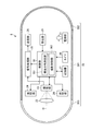
- FIG. 2 is a block diagram showing a functional configuration of the capsule endoscope apparatus according to the first embodiment of the present invention.
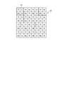
- FIG. 3 is a diagram schematically showing a color filter of the imaging unit in the capsule endoscope apparatus according to Embodiment 1 of the present invention.
- FIG. 4 is a flowchart showing an outline of processing executed by the capsule endoscope apparatus according to the first embodiment of the present invention.
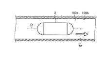
- FIG. 5A is a diagram illustrating an example of a state of a capsule endoscope in a lumen of a subject.
- FIG. 5A is a diagram illustrating an example of a state of a capsule endoscope in a lumen of a subject.
- FIG. 5B is a diagram illustrating an image corresponding to the image data captured by the imaging unit under the situation of FIG. 5A.
- FIG. 6A is a diagram illustrating an example of another state of the capsule endoscope apparatus in the lumen of a subject.
- 6B is a diagram illustrating an image corresponding to the image data captured by the imaging unit under the situation of FIG. 6A.
- FIG. 7A is a diagram illustrating an example of another state of the capsule endoscope apparatus in the lumen of a subject.
- FIG. 7B is a diagram illustrating an image corresponding to the image data captured by the imaging unit under the situation of FIG. 7A.
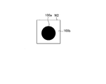
- FIG. 8 is a determination method for determining the position of a lumen in an image based on the luminance distribution measured by the luminance distribution measurement unit by the imaging control unit of the capsule endoscope apparatus according to the first embodiment of the present invention. It is a figure which shows typically the outline
- FIG. 9 is a diagram illustrating another example of the measurement method of the luminance distribution measurement unit of the capsule endoscope apparatus according to the modification of the first embodiment of the present invention.
- FIG. 10 is a flowchart showing an outline of processing executed by the capsule endoscope apparatus according to the second embodiment of the present invention.
- FIG. 11 is a block diagram illustrating a functional configuration of the capsule endoscope apparatus according to the third embodiment of the present invention.
- FIG. 12 is a flowchart showing an outline of processing executed by the capsule endoscope apparatus according to the third embodiment of the present invention.
- FIG. 13A is a diagram illustrating an example of a state of the capsule endoscope apparatus in the lumen of a subject.
- FIG. 13B is a diagram illustrating a first image corresponding to the first image data captured by the first imaging unit under the situation of FIG. 13A.
- FIG. 13C is a diagram illustrating a second image corresponding to the second image data captured by the second imaging unit under the situation of FIG. 13A.
- FIG. 14A is a diagram illustrating an example of another state of the capsule endoscope apparatus in the lumen of a subject.
- FIG. 13A is a diagram illustrating an example of a state of the capsule endoscope apparatus in the lumen of a subject.
- FIG. 14B is a diagram illustrating a first image corresponding to the first image data captured by the first imaging unit under the situation of FIG. 14A.
- FIG. 14C is a diagram illustrating a second image corresponding to the second image data captured by the second imaging unit under the situation of FIG. 14A.
- FIG. 15A is a diagram illustrating an example of another state of the capsule endoscope apparatus in the lumen of a subject.
- FIG. 15B is a diagram illustrating a first image corresponding to the first image data captured by the first imaging unit under the situation of FIG. 15A.
- FIG. 15C is a diagram illustrating a second image corresponding to the second image data captured by the second imaging unit under the situation of FIG. 15A.
- FIG. 1 is a schematic diagram showing a schematic configuration of a capsule endoscope system according to Embodiment 1 of the present invention.
- a capsule endoscope system 1 shown in FIG. 1 is transmitted from a capsule endoscope apparatus 2 that captures an in-vivo image in a subject 100 and a capsule endoscope apparatus 2 that is introduced into the subject 100.
- a receiving antenna unit 3 that receives a wireless signal
- a receiving antenna unit 3 that is detachably connected
- a receiving device 4 that records or displays the wireless signal received by the receiving antenna unit 3 by performing predetermined processing
- a capsule type An image processing device 5 for processing and / or displaying an image corresponding to the image data in the subject 100 imaged by the endoscope device 2.
- the capsule endoscope apparatus 2 has an imaging function for imaging the inside of the subject 100, a wireless communication function for transmitting in-vivo information including image data obtained by imaging the inside of the subject 100 to the receiving antenna unit 3, and Have The capsule endoscope apparatus 2 passes through the esophagus in the subject 100 by being swallowed into the subject 100, and moves in the body cavity of the subject 100 by the peristaltic movement of the digestive tract cavity. The capsule endoscope apparatus 2 sequentially images the inside of the body cavity of the subject 100 at a minute time interval, for example, 0.5 second interval (2 fps) while moving in the body cavity of the subject 100, and the taken subject 100 The image data is generated and transmitted to the receiving antenna unit 3 sequentially.
- the detailed configuration of the capsule endoscope apparatus 2 will be described later.
- the receiving antenna unit 3 includes receiving antennas 3a to 3h.
- the receiving antennas 3a to 3h receive radio signals from the capsule endoscope apparatus 2 and transmit them to the receiving apparatus 4.
- the receiving antennas 3a to 3h are configured using loop antennas, and are positions corresponding to predetermined positions on the external surface of the subject 100, for example, each organ in the subject 100 that is a passage path of the capsule endoscope apparatus 2. Placed in.
- the receiving device 4 records the image data in the subject 100 included in the radio signal transmitted from the capsule endoscope device 2 via the receiving antennas 3a to 3h, or an image corresponding to the image data in the subject 100. Is displayed.
- the receiving device 4 records position information of the capsule endoscope device 2, time information indicating time, and the like in association with image data received via the receiving antennas 3a to 3h.
- the receiving device 4 receives the signal while being inspected by the capsule endoscope device 2, for example, from the mouth of the subject 100 until it passes through the digestive tract and is discharged from the subject 100. It is stored in an apparatus holder (not shown) and carried by the subject 100.
- the receiving device 4 is removed from the subject 100 after the examination by the capsule endoscope device 2 is completed, and is connected to the image processing device 5 for transferring image data received from the capsule endoscope device 2.
- the image processing device 5 displays an image corresponding to the image data in the subject 100 acquired via the receiving device 4.
- the image processing device 5 includes a cradle 51 that reads image data and the like from the receiving device 4 and an operation input device 52 such as a keyboard and a mouse.
- the cradle 51 receives related information such as image data from the receiving device 4, position information associated with the image data, time information, and identification information of the capsule endoscope device 2.
- the acquired various information is transferred to the image processing apparatus 5.
- the operation input device 52 receives input from the user.
- the user While operating the operation input device 52, the user observes a living body part inside the subject 100, for example, the esophagus, stomach, small intestine, large intestine, and the like while viewing images in the subject 100 sequentially displayed by the image processing apparatus 5.
- the subject 100 is diagnosed.
- FIG. 2 is a block diagram showing a functional configuration of the capsule endoscope apparatus 2.
- the capsule endoscope apparatus 2 shown in FIG. 2 includes a housing 20, a power supply unit 21, an optical system 22, an imaging unit 23, an illumination unit 24, a signal processing unit 25, a transmission unit 26, and a recording. A unit 27, a timer 28, a receiving unit 29, and a control unit 30.
- the housing 20 has a capsule shape formed so as to be easily inserted into the subject 100.
- the housing 20 includes a cylindrical tube portion 201, a dome-shaped dome portion 202 and a dome portion 203 that respectively close the opening ends on both sides of the tube portion 201.
- the cylinder part 201 and the dome part 202 are formed using an opaque colored member that blocks visible light.
- the dome 203 is configured using an optical member that can transmit light in a predetermined wavelength band such as visible light. As shown in FIG.
- the casing 20 formed by the cylindrical portion 201, the dome portion 202, and the dome portion 203 includes a power supply unit 21, an optical system 22, an imaging unit 23, an illumination unit 24, a signal
- the processing unit 25, the transmission unit 26, the recording unit 27, the timer 28, the reception unit 29, and the control unit 30 are accommodated.
- the power supply unit 21 supplies power to each unit in the capsule endoscope apparatus 2.
- the power supply unit 21 is configured using a primary battery or secondary battery such as a button battery, and a power supply circuit that boosts the power supplied from the button battery.
- the power supply unit 21 has a magnetic switch, and switches the power supply on / off state by a magnetic field applied from the outside.
- the optical system 22 is configured using a plurality of lenses, and focuses reflected light of the illumination light irradiated by the illumination unit 24 on the imaging surface of the imaging unit 23 to form a subject image.
- the optical system 22 is disposed in the housing 20 so that the optical axis coincides with the central axis O in the longitudinal direction of the housing 20.
- the imaging unit 23 generates image data of the subject 100 by receiving a subject image formed by the optical system 22 on the light receiving surface and performing photoelectric conversion under the control of the control unit 30. Specifically, under the control of the control unit 30, the imaging unit 23 captures the subject 100 at a reference frame rate, for example, a frame rate of 4 fps, and generates image data of the subject 100.
- the image pickup unit 23 is an image pickup device such as a CCD (Charge Coupled Device) or a CMOS (Complementary Metal Oxide Semiconductor) composed of a plurality of pixels arranged two-dimensionally and a color filter stacked on each of the plurality of pixels. It is configured using.
- FIG. 3 is a diagram schematically illustrating the color filter 231 of the imaging unit 23.
- the color filter 231 is configured using a Bayer array color filter in which the filter Gr, the filter Gb, the filter R, and the filter B are a set T1.
- the imaging unit 23 is disposed in the housing 20 so that the light receiving surface of the imaging unit 23 is orthogonal to the central axis O.
- the illumination unit 24 irradiates illumination light toward the subject within the imaging field of the imaging unit 23 in synchronization with the frame rate of the imaging unit 23 under the control of the control unit 30. In addition, the illumination unit 24 irradiates illumination light toward a subject in the imaging field of the imaging unit 23 with a predetermined intensity under the control of the control unit 30.
- the illumination unit 24 is configured using an LED (Light Emitting Diode), a drive circuit, and the like.
- the signal processing unit 25 performs predetermined image processing on the image data input from the imaging unit 23 and outputs the image data to the transmission unit 26.
- the predetermined image processing is noise reduction processing, gain-up processing, or the like.
- the transmission unit 26 wirelessly transmits the image data sequentially input from the signal processing unit 25 to the outside.
- the transmission unit 26 is configured using a transmission antenna and a modulation circuit that modulates image data into a radio signal by performing signal processing such as modulation.
- the recording unit 27 records programs indicating various operations executed by the capsule endoscope apparatus 2, identification information for identifying the capsule endoscope apparatus 2, and the like.
- Timer 28 has a timekeeping function.
- the timer 28 outputs time measurement data to the control unit 30.
- the receiving unit 29 receives a radio signal transmitted from the outside and outputs it to the control unit 30.
- the reception unit 29 is configured using a reception antenna and a demodulation circuit that performs signal processing such as demodulation of a radio signal and outputs the signal to the control unit 30.
- the control unit 30 controls the operation of each unit of the capsule endoscope apparatus 2.
- the control unit 30 is configured using a CPU (Central Processing Unit).
- the control unit 30 includes a luminance distribution measurement unit 301 and a photographing control unit 302.
- the luminance distribution measuring unit 301 measures the luminance distribution of the image corresponding to the image data generated by the imaging unit 23.
- the imaging control unit 302 switches the frame rate of the imaging unit 23 based on the luminance distribution of the image measured by the luminance distribution measuring unit 301. Specifically, in the luminance distribution measured by the luminance distribution measuring unit 301, the imaging control unit 302 uses the frame rate of the imaging unit 23 as a reference frame when an area having a luminance lower than a predetermined value is distributed in the center of the image. When the frame rate is switched to a frame rate higher than the rate, and the region where the luminance is lower than the predetermined value is distributed outside the center of the image, the frame rate of the imaging unit 23 is switched to a frame rate lower than the reference frame rate.
- the imaging control unit 302 switches the frame rate of the imaging unit 23 from 4 fps to 8 fps when a region where the luminance is lower than a predetermined value is distributed in the center of the image.
- the frame rate of the imaging unit 23 is switched from 4 fps to 2 fps.
- the predetermined value is 0.3 when the full scale of luminance is assumed to be 1.
- the imaging control unit 302 adjusts the intensity of illumination light emitted by the illumination unit 24 based on the luminance distribution of the image measured by the luminance distribution measurement unit 301.
- FIG. 4 is a flowchart showing an outline of processing executed by the capsule endoscope apparatus 2.
- the imaging unit 23 images the imaging region irradiated with the illumination light by the illumination unit 24 (step S ⁇ b> 101).
- the luminance distribution measuring unit 301 measures the luminance distribution of the image corresponding to the image data generated by the imaging unit 23 (step S102).
- the imaging control unit 302 determines whether or not the region whose luminance is lower than the predetermined value is the central portion of the image based on the measurement result measured by the luminance distribution measuring unit 301 (step S103).
- the imaging control unit 302 determines that the low luminance region is the center of the image (step S103: Yes)
- the imaging control unit 302 has a higher frame rate than the reference frame rate.
- the mode is switched to (4 fps ⁇ 8 fps) (step S104).
- the capsule endoscope apparatus 2 proceeds to step S106 described later.
- step S103 when the shooting control unit 302 determines that the region whose luminance is lower than the predetermined value is not the central portion of the image (step S103: No), the shooting control unit 302 sets the frame rate of the imaging unit 23 from the reference frame. The frame rate is switched to a small low frame rate (4 fps ⁇ 2 fps) (step S105). After step S105, the capsule endoscope apparatus 2 proceeds to step S106 described later.
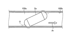
- FIG. 5A is a diagram illustrating an example of the state (state 1) of the capsule endoscope apparatus 2 in the lumen of the subject 100.
- FIG. FIG. 5B is a diagram illustrating an image corresponding to the image data captured by the imaging unit 23 under the situation of FIG. 5A.
- FIG. 6A is a diagram illustrating an example of another state (state 2) of the capsule endoscope apparatus 2 in the lumen of the subject 100.
- FIG. FIG. 6B is a diagram illustrating an image corresponding to the image data captured by the imaging unit 23 under the situation of FIG. 6A.
- FIG. 7A is a diagram illustrating an example of another state (state 3) of the capsule endoscope apparatus 2 in the lumen of the subject 100.
- FIG. FIG. 7B is a diagram illustrating an image corresponding to the image data captured by the imaging unit 23 under the situation of FIG. 7A.
- the capsule endoscope apparatus 2 has a lumen when the central axis O of the capsule endoscope apparatus 2 faces the lumen direction (arrow Ar) of the subject 100. Since no friction occurs, the moving speed in the lumen is increased. For this reason, when the frame rate of the imaging unit 23 is smaller than the reference frame rate (for example, 4 fps) (for example, 2 fps), the capsule endoscope apparatus 2 increases information on the lumen that cannot be imaged, while When the frame rate is larger than the reference frame rate (for example, 8 fps), information on lumens that cannot be photographed decreases.
- the reference frame rate for example, 4 fps
- the reference frame rate for example, 8 fps
- the central axis O of the capsule endoscope apparatus 2 is in the lumen direction (arrow Ar) of the subject 100.
- the capsule endoscope apparatus 2 captures information on the same lumen, and the frame rate of the imaging unit 23 is the reference frame. Even if the rate is smaller than the rate, information on the lumen that cannot be imaged does not occur.
- images taken by the capsule endoscope apparatus 2 are images W1 to W3 shown in FIGS. 5B to 7B, respectively.
- Each of the images W1 to W3 includes a lumen 100a and a lumen inner wall 100b.
- the lumen 100a is less reflected than the surrounding, for example, the lumen inner wall 100b, because the illumination light irradiated by the illumination unit 24 is less reflected.
- the lumen 100a has a luminance of almost zero.
- the distance that the capsule endoscope apparatus 2 travels the lumen per unit time is equal to the capsule in the lumen if the center axis O of the capsule endoscope apparatus 2 and the center of the lumen coincide with each other. Since the moving speed of the mold endoscope apparatus 2 is increased, the distance is increased. On the other hand, the distance that the capsule endoscope apparatus 2 travels through the lumen per unit time is such that the center axis O of the capsule endoscope apparatus 2 and the center of the lumen do not coincide with each other. The moving speed of the capsule endoscope apparatus 2 in the inside becomes slow. That is, the distance that the capsule endoscope apparatus 2 travels through the lumen per unit time is determined according to the direction of the lumen that the capsule endoscope apparatus 2 is photographing (condition 1).
- the amount of lumen information per unit time that can be acquired by the capsule endoscope apparatus 2 increases as the distance that the capsule endoscope apparatus 2 travels through the lumen per unit time increases (Condition 2).
- condition 3 the amount of lumen information per unit time that can be acquired by the capsule endoscope apparatus 2 also increases (condition 3).
- the frame rate of the imaging unit 23 in the capsule endoscope apparatus 2 is set according to the direction of the lumen in which the capsule endoscope apparatus 2 is photographing.
- the imaging control unit 302 determines the frame of the imaging unit 23 based on the luminance distribution measured with respect to the image corresponding to the image data generated by the imaging unit 23. Switch rates. That is, the imaging control unit 302 is a lumen whose brightness is lower than the surrounding area in the image corresponding to the image data generated by the imaging unit 23 based on the brightness distribution of the image measured by the brightness distribution measuring unit 301. The position of 100a is determined, and the frame rate of the imaging unit 23 is switched based on the determination result and the position in the image.
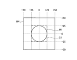
- FIG. 8 is a diagram schematically illustrating an outline of a determination method in which the imaging control unit 302 determines the position of the lumen in the image based on the luminance distribution measured by the luminance distribution measuring unit 301.
- the entire image range of the image for which the luminance distribution measuring unit 301 calculates the luminance is ⁇ 50 to +50 in the horizontal direction, ⁇ 50 to +50 in the vertical direction, and the region of the central portion C1 is ⁇ 25 to +25 in the horizontal direction.
- the vertical direction is -25 to +25.
- the lumen region M1 will be described as a circle.
- the imaging control unit 302 when the low-luminance region M1 is distributed in the central portion C1 of the image W4, the capsule endoscope apparatus 2 It is determined that the central axis O matches the lumen direction, that is, the lumen is present at the center C1 in the image.
- the imaging control unit 302 determines that the center of the capsule endoscope apparatus 2 when the low-luminance region M1 is distributed outside the central portion C1 of the image W4. It is determined that the axis O does not match the lumen direction, that is, there is a lumen other than the central portion C1 in the image.
- the imaging control unit 302 switches the frame rate of the imaging unit 23 based on the luminance distribution of the image measured by the luminance distribution measuring unit 301.
- step S106 when an instruction signal for instructing the end of the operation of the capsule endoscope apparatus 2 is input from the outside via the receiving unit 29, the operation of the capsule endoscope apparatus 2 is ended (step S106: Yes). The capsule endoscope apparatus 2 ends this process. On the other hand, when the instruction signal for instructing the end of the operation of the capsule endoscope apparatus 2 is not input from the outside via the receiving unit 29, the operation of the capsule endoscope apparatus 2 is not ended (step S106). : No), the capsule endoscope apparatus 2 returns to step S101.
- the imaging control unit 302 switches the frame rate of the imaging unit 23 based on the luminance distribution of the image measured by the luminance distribution measuring unit 301, the configuration is simple.
- the frame rate of the imaging unit 23 can be switched instantaneously.
- the information in the lumen is obtained by the imaging control unit 302 switching the frame rate of the imaging unit 23 under the condition of the capsule endoscope apparatus 2 in the lumen. Can be acquired efficiently, so that the power saving of the capsule endoscope apparatus 2 can be performed, and the operation time of the capsule endoscope apparatus 2 can be lengthened.
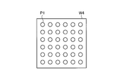
- the luminance distribution measuring unit 301 uses one type of pixel among the plurality of pixels constituting the imaging unit 23. However, as shown in FIG.
- the luminance distribution of the image may be measured using the luminance in the dotted area P1 (multi-spot photometry). Thereby, the calculation amount of the luminance distribution measuring unit 301 can be reduced.
- the capsule endoscope apparatus according to the second embodiment has the same configuration as that of the capsule endoscope apparatus 2 according to the first embodiment described above, and the processing to be executed is different. For this reason, below, the process which the capsule endoscope apparatus which concerns on this Embodiment 2 performs is demonstrated.
- symbol is attached
- FIG. 10 is a flowchart illustrating an outline of processing executed by the capsule endoscope apparatus 2 according to the second embodiment.
- step S201 and step S202 respectively correspond to step S101 and step S202 of FIG. 4 described above.
- step S203 the imaging control unit 302 switches the frame rate of the imaging unit 23 from the reference frame rate based on the luminance distribution measured by the luminance distribution measuring unit 301.
- the imaging control unit 302 switches the frame rate of the imaging unit 23 from 4 fps to 8 fps based on the luminance distribution measured by the luminance distribution measurement unit 301.
- the imaging unit 23 images the imaging region irradiated with the illumination light by the illumination unit 24 (step S204).
- the imaging control unit 302 determines whether or not a predetermined time has elapsed after switching the frame rate of the imaging unit 23 from the reference frame rate based on the time data input from the timer 28 (step S205). ).
- a predetermined time for example, 30 seconds has elapsed after switching the frame rate of the imaging unit 23 from the reference frame rate (step S205: Yes)
- the capsule endoscope apparatus 2 The process proceeds to step S206 described later.
- the imaging control unit 302 determines that the predetermined time has not elapsed after switching the frame rate of the imaging unit 23 from the reference frame rate (step S205: No)
- the capsule endoscope apparatus 2 Return to step S204.
- step S206 the imaging control unit 302 switches the frame rate of the imaging unit 23 to the reference frame rate. Specifically, the imaging control unit 302 switches the frame rate of the imaging unit 23 from, for example, 8 fps to 4 fps.
- step S207: Yes when an instruction signal instructing the end of the operation of the capsule endoscope apparatus 2 is input from the outside via the receiving unit 29 and the operation of the capsule endoscope apparatus 2 is ended (step S207: Yes), The capsule endoscope apparatus 2 ends this process.
- step S207 when the instruction signal for instructing the end of the operation of the capsule endoscope apparatus 2 is not input from the outside via the receiving unit 29, the operation of the capsule endoscope apparatus 2 is not ended (step S207). : No), the capsule endoscope apparatus 2 returns to step S201.
- the imaging control unit 302 since the imaging control unit 302 switches the frame rate of the imaging unit 23 based on the luminance distribution of the image measured by the luminance distribution measuring unit 301, the configuration is simple.
- the frame rate of the imaging unit 23 can be switched instantaneously.
- a predetermined time elapses after the imaging control unit 302 switches the frame rate of the imaging unit 23 from the reference frame rate based on the time data input from the timer 28.
- the information in the lumen can be efficiently acquired by switching the frame rate of the imaging unit 23 to the reference frame rate, so that the power saving of the capsule endoscope apparatus 2 can be performed. it can.
- the capsule endoscope apparatus according to the third embodiment is different in configuration from the capsule endoscope apparatus 2 according to the first embodiment described above.
- the capsule endoscope apparatus according to the present embodiment includes two imaging units that image different imaging regions. For this reason, in the following, after describing the configuration of the capsule endoscope apparatus according to the third embodiment, a process executed by the capsule endoscope apparatus according to the third embodiment will be described.
- symbol is attached
- FIG. 11 is a block diagram illustrating a functional configuration of the capsule endoscope apparatus according to the third embodiment.
- a capsule endoscope apparatus 2a shown in FIG. 11 includes an optical system 31, an imaging unit 32, and an illumination unit 33 in addition to the configuration of the capsule endoscope apparatus 2 according to the first embodiment described above.
- the capsule endoscope apparatus 2a includes a casing 20a instead of the casing 20 and the control unit 30 of the capsule endoscope apparatus 2 according to the first embodiment described above.
- the housing 20a has a capsule shape formed so as to be easily inserted into the subject 100.
- the housing 20a includes a cylindrical tube portion 201, and a dome-shaped dome portion 202a and a dome portion 203 that respectively close the opening ends on both sides of the tube portion 201.
- the dome 202a is configured using an optical member that can transmit light in a predetermined wavelength band such as visible light.
- the housing 20a is arranged on the central axis in the longitudinal direction of the capsule endoscope apparatus 2a, and houses the imaging unit 23 and the imaging unit 32 that capture different imaging regions.
- the optical system 31 has the same configuration as the optical system 22 described above, and focuses the reflected light of the illumination light irradiated by the illumination unit 33 on the imaging surface of the imaging unit 32 to form a subject image.
- the optical system 31 is arranged in the housing 20a so that the optical axis coincides with the central axis O in the longitudinal direction of the housing 20a.
- the imaging unit 32 has a configuration similar to that of the imaging unit 23 described above. Under the control of the control unit 30, the optical system 31 receives a subject image formed on the light receiving surface and performs photoelectric conversion. Image data of the subject 100 is generated. Further, the imaging unit 32 is disposed in the housing 20 a so that the light receiving surface of the imaging unit 32 is orthogonal to the central axis O. In the third embodiment, the imaging unit 23 functions as a first imaging unit, and the imaging unit 32 functions as a second imaging unit. Therefore, hereinafter, the imaging unit 23 will be described as the first imaging unit 23, and the imaging unit 32 will be described as the second imaging unit 32.
- the illumination unit 33 has the same configuration as the illumination unit 24 described above, and is directed toward a subject in the imaging field of the imaging unit 32 in synchronization with the frame rate of the imaging unit 32 under the control of the control unit 30. Irradiate with illumination light.
- FIG. 12 is a flowchart showing an outline of processing executed by the capsule endoscope apparatus 2a.
- the imaging control unit 302 first irradiates the illumination unit 24 and the illumination unit 33 with illumination light, and performs first imaging on an imaging region in which the illumination unit 24 and the illumination unit 33 irradiate irradiation light.
- the unit 23 and the second imaging unit 32 are caused to capture images (step S301).
- the luminance distribution measurement unit 301 measures the luminance distribution of each of the two images corresponding to the two image data generated by the first imaging unit 23 and the second imaging unit 32 (step S302).
- the imaging control unit 302 has a region whose luminance is lower than a predetermined value in the luminance distribution of each of the two images generated by the first imaging unit 23 and the second imaging unit 32 measured by the luminance distribution measuring unit 301. It is determined whether or not the center portion (step S303). In the luminance distribution of each of the two images generated by the first imaging unit 23 and the second imaging unit 32 measured by the luminance distribution measuring unit 301 by the imaging control unit 302, a region where the luminance is lower than a predetermined value is the central portion of the image. (Step S303: Yes), the imaging control unit 302 switches the frame rates of the first imaging unit 23 and the second imaging unit 32 to a higher frame rate than the reference frame rate (step S304).
- the imaging control unit 302 switches the frame rate of the first imaging unit 23 and the second imaging unit 32 from the standard 4 fps to the high frame rate of 16 fps (4 fps ⁇ 16 fps).
- the capsule endoscope apparatus 2a proceeds to step S306 described later.
- step S303 in the luminance distribution of each of the two images generated by the first imaging unit 23 and the second imaging unit 32 measured by the luminance distribution measuring unit 301 by the imaging control unit 302, an area whose luminance is lower than a predetermined value is an image. If it is determined that it is not the central portion (step S303: No), the imaging control unit 302 switches the frame rates of the first imaging unit 23 and the second imaging unit 32 to a lower frame rate that is smaller than the reference frame rate (step S305). Specifically, the imaging control unit 302 switches the frame rate of the first imaging unit 23 and the second imaging unit 32 from the standard 4 fps to the low frame rate of 2 fps (4 fps ⁇ 2 fps). After step S305, the capsule endoscope apparatus 2a proceeds to step S306 described later.
- the first imaging unit 23 and the second imaging unit based on the luminance distribution obtained by the imaging control unit 302 measuring the two images generated by the first imaging unit 23 and the second imaging unit 32 by the luminance distribution measuring unit 301, the first imaging unit 23 and the second imaging unit. A situation where 32 frame rates are switched will be described.
- FIG. 13A is a diagram illustrating an example of the state (state 1) of the capsule endoscope apparatus 2a in the lumen of the subject 100.
- FIG. 13B is a diagram illustrating a first image corresponding to the first image data captured by the first imaging unit 23 under the situation of FIG. 13A.
- FIG. 13C is a diagram illustrating a second image corresponding to the second image data captured by the second imaging unit 32 under the situation of FIG. 13A.
- 14A is a diagram showing an example of another state (state 2) of the capsule endoscope apparatus 2a in the lumen of the subject 100.
- FIG. FIG. 14B is a diagram illustrating a first image corresponding to the first image data captured by the first imaging unit 23 under the situation of FIG. 14A.
- FIG. 14C is a diagram illustrating a second image corresponding to the second image data captured by the second imaging unit 32 under the situation of FIG. 14A.
- FIG. 15A is a diagram illustrating an example of another state (state 3) of the capsule endoscope apparatus 2a in the lumen of the subject 100.
- FIG. 15B is a diagram illustrating a first image corresponding to the first image data captured by the first imaging unit 23 under the situation of FIG. 15A.
- FIG. 15C is a diagram illustrating a second image corresponding to the second image data captured by the second imaging unit 32 under the situation of FIG. 15A.
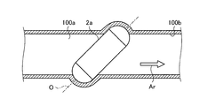
- the capsule endoscope apparatus 2a performs the first imaging when the central axis O of the capsule endoscope apparatus 2a and the lumen direction (arrow Ar) of the subject 100 coincide with each other.
- the lumen 100a is included in the center of each of the first image W10 and the second image W11 generated by the unit 23 and the second imaging unit 32 (see FIGS. 13B and 13C).
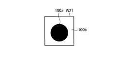
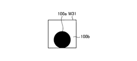
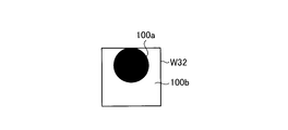
- the central axis O of the capsule endoscope apparatus 2a and the lumen direction (arrow Ar) of the subject 100 are the same. If not, for example, if the optical axis of one of the first imaging unit 23 and the second imaging unit 32 is deviated from the lumen direction of the subject, the first imaging unit 23 and the second imaging unit 32 generate The first image W21 and the second image W22 to be taken, or the first image W31 and the second image W32 are taken at positions where the lumen 100a is shifted from the center.
- the imaging control unit 302 includes two images based on the luminance distributions of the two images generated by the first imaging unit 23 and the second imaging unit 32 measured by the luminance distribution measuring unit 301, respectively.
- the frame rate of each of the first imaging unit 23 and the second imaging unit 32 is switched to a higher frame rate than the reference frame rate (4 fps). ⁇ 16 fps).
- the imaging control unit 302 distributes the range where the luminance is lower than the predetermined value in the two images generated by the first imaging unit 23 and the second imaging unit 32 to the peripheral part which is shifted from the central part.
- the frame rate of each of the first imaging unit 23 and the second imaging unit 32 is switched to a lower frame rate that is smaller than the reference frame rate (4 fps ⁇ 2 fps).
- step S306 when an instruction signal for instructing the end of the operation of the capsule endoscope apparatus 2a is input from the outside via the receiving unit 29, the operation of the capsule endoscope apparatus 2a is ended (step S306: Yes).
- step S306 Yes
- step S306 Yes
- step S306 Yes
- step S306 No
- step S306 No
- the capsule endoscope apparatus 2a returns to Step S301.
- the first imaging unit 23 and the second imaging unit based on the luminance distributions of the first image and the second image measured by the luminance distribution measuring unit 301 by the imaging control unit 302. Since the 32 frame rates are switched, the frame rate can be switched instantaneously with a simple configuration.
- the imaging control unit 302 switches the frame rates of the first imaging unit 23 and the second imaging unit 32 in the situation of the capsule endoscope apparatus 2a in the lumen.
- the information in the lumen of the subject 100 can be efficiently acquired, so that the power consumption of the capsule endoscope apparatus 2a can be reduced, and the operation time of the capsule endoscope apparatus 2a can be reduced. Can be lengthened.
- the first imaging unit 23 and the second imaging unit 32 are based on the luminance distributions of the first image and the second image measured by the luminance distribution measuring unit 301 by the imaging control unit 302.
- the frame rate of the first imaging unit 23 and the second imaging unit 32 is changed when a predetermined time has elapsed after the switching of the frame rate of the first imaging unit 23 and the second imaging unit 32. May be switched to a reference frame rate (for example, 16 fps ⁇ 4 fps). Thereby, the information in a lumen can be acquired efficiently.
- the luminance distribution measurement unit 301 uses a predetermined one type of pixel of each of the first image and the second image generated by the first imaging unit 23 and the second imaging unit 32. Although the luminance distribution is measured, the luminance distribution may be measured using the luminance in the plurality of point-like regions P1 of the first image and the second image, respectively (see FIG. 9). Thereby, the calculation amount of the luminance distribution measuring unit 301 can be reduced.
- the imaging control unit 302 switches the frame rates of the first imaging unit 23 and the second imaging unit 32 to match, but the first imaging unit 23 and the second imaging unit 32 There is no need to match the frame rates. For example, only the first imaging unit 23 may be switched to a high frame rate.
- the present invention can include various embodiments not described herein, and various design changes can be made within the scope of the technical idea specified by the claims. It is.
Abstract
L'invention concerne un appareil du type vidéocapsule endoscopique pouvant commuter instantanément la fréquence de trame d'une unité de capture d'image à l'aide d'une configuration simple. L'appareil du type vidéocapsule endoscopique (2) comprend : une unité de capture d'image (23) pour capturer des images à l'intérieur d'un sujet et générer des données d'image de l'intérieur du sujet ; une section de mesure de distribution de luminosité (301) pour mesurer la distribution de luminosité d'images correspondant aux données d'image générées par l'unité de capture d'image (23) ; et une section de commande d'imagerie (302) pour commuter la fréquence de trame de l'unité de capture d'image (23) sur la base de la distribution de luminosité mesurée par l'unité de mesure de distribution de luminosité (301).
Priority Applications (2)
| Application Number | Priority Date | Filing Date | Title |
|---|---|---|---|
| JP2015532212A JP5815166B1 (ja) | 2014-05-26 | 2015-02-24 | カプセル型内視鏡装置 |
| US14/993,504 US9763565B2 (en) | 2014-05-26 | 2016-01-12 | Capsule endoscope device |
Applications Claiming Priority (2)
| Application Number | Priority Date | Filing Date | Title |
|---|---|---|---|
| JP2014108413 | 2014-05-26 | ||
| JP2014-108413 | 2014-05-26 |
Related Child Applications (1)
| Application Number | Title | Priority Date | Filing Date |
|---|---|---|---|
| US14/993,504 Continuation US9763565B2 (en) | 2014-05-26 | 2016-01-12 | Capsule endoscope device |
Publications (1)
| Publication Number | Publication Date |
|---|---|
| WO2015182185A1 true WO2015182185A1 (fr) | 2015-12-03 |
Family
ID=54698527
Family Applications (1)
| Application Number | Title | Priority Date | Filing Date |
|---|---|---|---|
| PCT/JP2015/055201 WO2015182185A1 (fr) | 2014-05-26 | 2015-02-24 | Appareil du type vidéocapsule endoscopique |
Country Status (2)
| Country | Link |
|---|---|
| US (1) | US9763565B2 (fr) |
| WO (1) | WO2015182185A1 (fr) |
Cited By (1)
| Publication number | Priority date | Publication date | Assignee | Title |
|---|---|---|---|---|
| WO2019003597A1 (fr) * | 2017-06-26 | 2019-01-03 | オリンパス株式会社 | Dispositif de traitement d'image, système d'endoscope à capsule, procédé de fonctionnement d'un dispositif de traitement d'image et programme de fonctionnement d'un dispositif de traitement d'image |
Families Citing this family (3)
| Publication number | Priority date | Publication date | Assignee | Title |
|---|---|---|---|---|
| US10143364B2 (en) * | 2015-07-23 | 2018-12-04 | Ankon Technologies Co., Ltd | Controlled image capturing method including position tracking and system used therein |
| JP7073145B2 (ja) * | 2018-03-12 | 2022-05-23 | ソニー・オリンパスメディカルソリューションズ株式会社 | 医療用調光制御装置、および医療用調光制御装置の作動方法 |
| CN109480746A (zh) * | 2019-01-14 | 2019-03-19 | 深圳市资福医疗技术有限公司 | 智能控制胶囊式内窥镜在消化道不同部位工作方法及装置 |
Citations (6)
| Publication number | Priority date | Publication date | Assignee | Title |
|---|---|---|---|---|
| JP2004154176A (ja) * | 2002-11-01 | 2004-06-03 | Olympus Corp | 内視鏡撮像装置 |
| JP2004521662A (ja) * | 2000-05-15 | 2004-07-22 | ギブン・イメージング・リミテツド | インビボカメラのキャプチャレートおよび表示レートを制御するためのシステム |
| WO2006100808A1 (fr) * | 2005-03-22 | 2006-09-28 | Osaka University | Controleur d’affichage d’images pour endoscope a capsule |
| US7623690B2 (en) * | 2004-03-30 | 2009-11-24 | Carestream Health, Inc. | System and method for classifying in vivo images according to anatomical structure |
| JP2010524557A (ja) * | 2007-09-06 | 2010-07-22 | アイスリーシステム コーポレーション | 画像のフレームレートを制御できるカプセル型内視鏡 |
| WO2014042096A1 (fr) * | 2012-09-11 | 2014-03-20 | オリンパス株式会社 | Système médical |
Family Cites Families (5)
| Publication number | Priority date | Publication date | Assignee | Title |
|---|---|---|---|---|
| US8401262B2 (en) * | 2001-06-20 | 2013-03-19 | Given Imaging, Ltd | Device, system and method for motility measurement and analysis |
| US20060184039A1 (en) * | 2001-07-26 | 2006-08-17 | Dov Avni | Apparatus and method for light control in an in-vivo imaging device |
| US7195588B2 (en) | 2004-03-01 | 2007-03-27 | Olympus Corporation | Endoscope image pick-up apparatus |
| JP5035987B2 (ja) | 2008-01-28 | 2012-09-26 | 富士フイルム株式会社 | カプセル内視鏡、およびカプセル内視鏡の動作制御方法 |
| US9324145B1 (en) * | 2013-08-08 | 2016-04-26 | Given Imaging Ltd. | System and method for detection of transitions in an image stream of the gastrointestinal tract |
-
2015
- 2015-02-24 WO PCT/JP2015/055201 patent/WO2015182185A1/fr active Application Filing
-
2016
- 2016-01-12 US US14/993,504 patent/US9763565B2/en active Active
Patent Citations (6)
| Publication number | Priority date | Publication date | Assignee | Title |
|---|---|---|---|---|
| JP2004521662A (ja) * | 2000-05-15 | 2004-07-22 | ギブン・イメージング・リミテツド | インビボカメラのキャプチャレートおよび表示レートを制御するためのシステム |
| JP2004154176A (ja) * | 2002-11-01 | 2004-06-03 | Olympus Corp | 内視鏡撮像装置 |
| US7623690B2 (en) * | 2004-03-30 | 2009-11-24 | Carestream Health, Inc. | System and method for classifying in vivo images according to anatomical structure |
| WO2006100808A1 (fr) * | 2005-03-22 | 2006-09-28 | Osaka University | Controleur d’affichage d’images pour endoscope a capsule |
| JP2010524557A (ja) * | 2007-09-06 | 2010-07-22 | アイスリーシステム コーポレーション | 画像のフレームレートを制御できるカプセル型内視鏡 |
| WO2014042096A1 (fr) * | 2012-09-11 | 2014-03-20 | オリンパス株式会社 | Système médical |
Cited By (1)
| Publication number | Priority date | Publication date | Assignee | Title |
|---|---|---|---|---|
| WO2019003597A1 (fr) * | 2017-06-26 | 2019-01-03 | オリンパス株式会社 | Dispositif de traitement d'image, système d'endoscope à capsule, procédé de fonctionnement d'un dispositif de traitement d'image et programme de fonctionnement d'un dispositif de traitement d'image |
Also Published As
| Publication number | Publication date |
|---|---|
| US20160120396A1 (en) | 2016-05-05 |
| US9763565B2 (en) | 2017-09-19 |
Similar Documents
| Publication | Publication Date | Title |
|---|---|---|
| KR100800040B1 (ko) | 체내 촬상용 캡슐 | |
| JP4422679B2 (ja) | カプセル内視鏡およびカプセル内視鏡システム | |
| JPWO2004096029A1 (ja) | カプセル内視鏡およびカプセル内視鏡システム | |
| US10299665B2 (en) | Imaging device and capsule endoscope system | |
| WO2015182185A1 (fr) | Appareil du type vidéocapsule endoscopique | |
| US20170196442A1 (en) | Capsule endoscope system | |
| JPWO2016088427A1 (ja) | カプセル型内視鏡システム及びカプセル型内視鏡システムの作動方法 | |
| US20170258304A1 (en) | Imaging device, endoscope, and capsule endoscope | |
| EP2353491B1 (fr) | Dispositif d'introduction d'un objet à l'intérieur de l'organisme d'un sujet et système d'acquisition d'informations in vivo | |
| JP5977907B1 (ja) | カプセル型内視鏡及びカプセル型内視鏡システム | |
| JP5815166B1 (ja) | カプセル型内視鏡装置 | |
| US20170276847A1 (en) | Imaging system | |
| US10939037B2 (en) | Capsule endoscope, receiving device, operation method of capsule endoscope, and computer readable recording medium | |
| JP4656824B2 (ja) | 無線型被検体内情報取得装置 | |
| US20160317002A1 (en) | Capsule endoscope apparatus | |
| JP6230511B2 (ja) | 内視鏡装置 | |
| WO2016084500A1 (fr) | Capsule endoscopique, système d'activation de capsule endoscopique et système d'examen | |
| JP2019201757A (ja) | カプセル型内視鏡、カプセル型内視鏡システム及びカプセル型内視鏡の送信方法 | |
| JP2006305322A (ja) | カプセル内視鏡システム | |
| JP6275344B1 (ja) | 動き判定装置、被検体内導入装置、動き判定方法及びプログラム | |
| WO2022190256A1 (fr) | Dispositif d'acquisition d'informations sur un sujet, système d'inspection, procédé de commande et programme | |
| EP3173010B1 (fr) | Endoscope de type capsule passive pour l'intestin | |
| JP2016073341A (ja) | カプセル型医療装置 |
Legal Events
| Date | Code | Title | Description |
|---|---|---|---|
| ENP | Entry into the national phase |
Ref document number: 2015532212 Country of ref document: JP Kind code of ref document: A |
|
| 121 | Ep: the epo has been informed by wipo that ep was designated in this application |
Ref document number: 15799216 Country of ref document: EP Kind code of ref document: A1 |
|
| NENP | Non-entry into the national phase |
Ref country code: DE |
|
| 122 | Ep: pct application non-entry in european phase |
Ref document number: 15799216 Country of ref document: EP Kind code of ref document: A1 |