WO2014041998A1 - 自立式表示装置、自立式表示装置の板材 - Google Patents
自立式表示装置、自立式表示装置の板材 Download PDFInfo
- Publication number
- WO2014041998A1 WO2014041998A1 PCT/JP2013/072780 JP2013072780W WO2014041998A1 WO 2014041998 A1 WO2014041998 A1 WO 2014041998A1 JP 2013072780 W JP2013072780 W JP 2013072780W WO 2014041998 A1 WO2014041998 A1 WO 2014041998A1
- Authority
- WO
- WIPO (PCT)
- Prior art keywords
- plate
- display
- self
- supporting
- display device
- Prior art date
- Legal status (The legal status is an assumption and is not a legal conclusion. Google has not performed a legal analysis and makes no representation as to the accuracy of the status listed.)
- Ceased
Links
Images







Classifications
-
- G—PHYSICS
- G09—EDUCATION; CRYPTOGRAPHY; DISPLAY; ADVERTISING; SEALS
- G09F—DISPLAYING; ADVERTISING; SIGNS; LABELS OR NAME-PLATES; SEALS
- G09F1/00—Cardboard or like show-cards of foldable or flexible material
- G09F1/04—Folded cards
- G09F1/06—Folded cards to be erected in three dimensions [3D]
-
- G—PHYSICS
- G09—EDUCATION; CRYPTOGRAPHY; DISPLAY; ADVERTISING; SEALS
- G09F—DISPLAYING; ADVERTISING; SIGNS; LABELS OR NAME-PLATES; SEALS
- G09F7/00—Signs, name or number plates, letters, numerals, or symbols; Panels or boards
Definitions
- the present invention relates to an assembly-type self-supporting display device and a plate material of the self-supporting display device.
- An object of the present invention is to provide a self-supporting display device that is easy to assemble and a plate material for the self-supporting display device.
- the present invention solves the problems by the following means.
- symbol corresponding to embodiment of this invention is attached
- the configuration described with reference numerals may be improved as appropriate, or at least a part thereof may be replaced with another configuration.
- -1st invention is the 1st display board (10,610,710), the 1st side board (11,611) rotatably connected to the side of the said 1st display board, and the said 1st display
- a support plate (40, 540, 640, 740) connected to the side and rotatably connected to the back surface of the first display plate.
- the first side plate is connected to the first display plate.
- the second side panel stands up with respect to the second display panel.
- the first side plate and the second side plate are respectively the first display plate and the second display plate.
- the first display plate and the second display plate that are flatly developed in a longitudinal cross-sectional shape while maintaining the state of rising from the plate and maintaining the state in which the first display plate and the second display plate are flatly developed.
- the display panel, the bottom plate, and the support plate form each side of a triangle (70) to maintain an open state.
- the second invention is the self-supporting display device of the first invention, wherein the first display plate (10, 610, 710) and the first side plate (11, 611) are the first display plate and the first display device.
- the second display plate (20, 620, 720) and the second side plate (21, 521, 621) are rotated at the connection part between the first side plates, and the second display plate and the second display plate.
- the first display panel and the second display panel are rotated and folded at the connection part between the first display panel and the second display panel, and rotated flat at the connection part between the side panels.
- the second side plate and the bottom plate (30, 630, 730) are rotated and folded at a connection portion between the second side plate and the bottom plate, and the bottom plate and the support plate (40, 540, 640, 740) are The support plate is rotated and folded at the connection between the bottom plate and the support plate.
- the first display panel is folded so as to be in close contact with the support plate and the first display panel, and the self-supporting display device is folded flat as a whole.
- This is a self-supporting display device.
- -3rd invention is a self-supporting display apparatus of 1st or 2nd invention, The said 1st side plate (11,611) stood up with respect to the said 1st display plate (10,610,710) in the 1st invention.
- the first side plate or the second side plate is maintained so that the second side plate (21, 521, 621) is maintained upright with respect to the second display plate (20, 620, 720).
- It is a self-supporting display device characterized by comprising urging members (50, 350, 550 (550-1, 550-2), 650) for urging the inside.
- -4th invention is the self-supporting display apparatus of any one of 1st to 3rd invention, and a biasing member urges
- the first display plate and the second display plate are flatly developed in conjunction with the rising of the first side plate and the second side plate, and the first display plate is flattened.
- the self-supporting display device wherein the first display panel, the second display panel, the bottom plate (30), and the support plate (40) are deformed from the folded state to the open state.
- -5th invention is the self-supporting display apparatus of 4th invention, One end is connected to the said 1st side plate (11) or the said 2nd side plate (521), and the other end is the said support member in the said biasing member.
- the self-supporting display device is characterized by being an elastic member (550 (550-1, 550-2)) connected from the inner surface to the plate (540).
- the -6th invention is the self-supporting display apparatus of 4th invention,
- the said biasing member is an expansion-contraction by which one end was connected to the said 2nd side plate and the other end was connected from the inner surface with respect to the said baseplate.
- It is a self-supporting display device characterized by being a member.
- the seventh invention is the self-supporting display device of the fifth or sixth invention, wherein the first side plate (611) or the second side plate (621) of the biasing member (650) is attached (623, 623) 626) is a self-supporting display device that is biased inward and abuts against the outer end of the support plate (640).
- the eighth invention is the self-supporting display device of any of the fifth to seventh inventions, wherein at least one of the second display plate (620) and the support plate (740) is the bottom plate (630, 763), and the second side plate (621, 721) is in contact with the outer end portion of the bottom plate.
- the ninth invention is the self-supporting display device according to any one of the first to eighth inventions, wherein the second side plate (621, 721) is closer to the front side than the second display plate (620, 720). It is a self-supporting display device characterized by having protruding feet (625, 725).
- the tenth invention is the self-supporting display device of any one of the first to ninth inventions, wherein the length obtained by adding the length of the second display panel (20) and the length of the bottom panel (30) is L1, and the length of the support plate (40) and the length of the connection portion of the support plate and the first display plate (10) and the connection portion of the first display plate and the second display plate are added.
- the eleventh aspect of the invention is the self-supporting display device according to any one of the first to ninth aspects of the invention, wherein the connection part (660) of the first display panel (610, 710) and the second display panel (620, 720).
- L61 L62 + L63
- the twelfth invention is a plate material processed into the self-supporting display device of any one of the first to eleventh inventions, wherein the support plate (40, 540, 640, 740) A connection part (66a) for connecting the other side to the back surface of the second display panel in a state separated from the back surface of the second display panel (20, 620, 720), so that the support plate can rotate. It is the board
- a self-supporting display device that can be easily assembled can be provided.
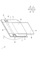
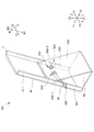
- FIG. 1 is a perspective view of a self-supporting display device 1 according to the first embodiment in a self-supporting state.
- FIG. 2 is a sectional view and a rear view of the self-supporting display device 1 according to the first embodiment in a self-supporting state.
- FIG. 2A is a cross-sectional view of the self-supporting display device 1 (cross-sectional view taken along the line 2a-2a in FIG. 1).
- FIG. 2B is a view of the connection portion of the first display plate 10, the first side plate 11, the second display plate 20, and the second side plate 21 as seen from the back side. In FIG. 2B, the support plate 40 is not shown.
- FIG. 2C is a vertical cross-sectional view of the self-supporting display device 1 (a cross-sectional view taken along 2c-2c in FIG. 1).
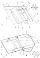
- FIG. 3 is a perspective view illustrating a holding structure for the first display plate 10, the first side plate 11, the second display plate 20, and the second side plate 21 according to the first embodiment.
- the left-right direction when the self-standing display device 1 is installed in the vertical direction Z is described as X
- the depth direction is described as Y.
- the vertical direction of the surface directions of the first display panel 10 and the second display panel 20 is the coordinate W, the first display panel 10 and the second display panel 20.
- a VW coordinate system is provided with the normal direction of the surface of FIG.
- the front side Y1 is the front side and the back side Y2 is the back side as appropriate with reference to the state of FIG.
- the self-supporting display device 1 is provided with a display on the surfaces of the first display panel 10 and the second display panel 20 by, for example, printing.
- the use of the self-supporting display device 1 is, for example, a signboard or the like that provides a display (not shown) such as an advertisement and serves as a storefront of a store.
- the total height of the self-supporting display device 1 is, for example, about 300 to 2000 mm.
- the use and size of the self-supporting display device 1 are not limited to this.
- the self-supporting display device 1 includes a first display plate 10, a first side plate 11, a second display plate 20, a second side plate 21, a bottom plate 30, a support plate 40, rubber 50 (biasing member), and hinges 60 to 66. .
- the first display plate 10, the first side plate 11, the second display plate 20, the second side plate 21, the bottom plate 30, and the support plate 40 are made of a paper material, a resin plate, a member obtained by bonding a paper material to a foamed resin plate, or the like. It is formed. Each plate has sufficient strength to allow the self-supporting display device 1 to be installed independently.
- the hinges 60 to 66 are plate members that rotatably connect the plate members.
- the hinges 60 to 66 are formed of a paper material, a member obtained by bonding an adhesive tape to a resin sheet, or the like, and can be bonded to each plate material.
- the first display panel 10 is a display panel arranged in the upper stage.
- the first side plate 11 is connected to the left and right sides of the first display plate 10.
- the second display panel 20 is a display panel connected to the lower stage of the first display panel 10.
- the second side plates 21 are connected to the left and right sides of the second display plate 20, respectively.
- the bottom plate 30 is connected to the lower side of the second side plate 21.
- the support plate 40 is connected to the bottom plate 30 on the back Y2 side. Further, the support plate 40 is attached to the back surface of the first display panel 10 on the side opposite to the bottom plate 30 side.
- the rubber 50 is a rubber band (rubber rubber) that urges the second side plate 21 inward in the left-right direction X.
- the rubber 50 is hooked on the notch 23 of the second side plate 21.
- the rubber 50 urges the two second side plates 21 in the left-right direction X so as to attract the two side plates 21 and urges the rubber 50 from the expanded state to the contracted state.
- the urging member is not limited to the rubber 50, and may be any form as long as it is a member that urges the second side plate 21 inward.
- the urging member may be a member obtained by sticking a leaf spring or the like bent at 90 ° to inner corner portions of the second display plate 20 and the second side plate 21.
- the first display panel 10 and the second display panel 20 are rotatably connected by a hinge 60.
- the first display panel 10 and the first side panel 11 are rotatably connected by a hinge 61.
- the second side plate 21 and the second display plate 20 are rotatably connected by a hinge 62.
- the first side plate 11 and the second side plate 21 are rotatably connected by a hinge 63.
- the second display panel 20 and the bottom panel 30 are rotatably connected by a hinge 64.
- the bottom plate 30 and the support plate 40 are rotatably connected by a hinge 65.
- the support plate 40 is rotatably connected to the back surface of the first display plate 10 by a hinge 66.
- the self-supporting display device 1 is integrally formed by connecting the plate members by the hinges 60 to 66. For this reason, the self-supporting display device 1 can be easily assembled without having to incorporate new parts after the hinges 60 to 66 and the rubber 50 are assembled.
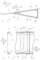
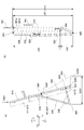
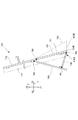
- the self-supporting structure of the self-supporting display device 1 will be described. As shown in FIG. 2C, the first display panel 10 (the portion between the hinge 60 and the hinge 66), the second display panel 20, the bottom panel 30, and the support panel 40 form each side of the triangle 70. And it will be in an open state.
- the 1st display board 10 and the 2nd display board 20 rotate with the hinge 60, this triangle 70 will deform
- the rubber 50 urges the second side plate 21 inward.
- the first side plate 11 and the second side plate 21 are connected by the hinge 63, the first side plate 11 is urged inward in conjunction with the second side plate 21.
- the first side plate 11 is applied to the support plate 40 and maintained in a state of rising from the first display plate 10, and the angle formed by the first side plate 11 and the first display plate 10 is 90 °. Retained.
- the second side plate 21 is maintained in a state of rising from the second display plate 20, and the second side plate 21 and the second side plate 21 are also connected.
- the angle formed by the two display panels 20 is maintained at 90 °.
- the state in which the first side plate 11 stands at 90 ° with respect to the first display plate 10 is maintained by the biasing force of the rubber 50 and the stopper function of the support plate 40, and the second side plate 21 is the second side plate 21.
- the state where the display panel 20 stands up to 90 ° is maintained.
- the support plate 40 is configured so as to have both a stopper function and a function of suppressing the collapse described later.
- the 1st side board 11 and the 2nd side board 21 are united, and the 1st display board 10 side and the 2nd display board 20 are controlled so that it may not rotate the hinge 60 periphery. Thereby, the state which the 1st display board 10 side and the 2nd display board 20 developed flat (180 degrees) is maintained.
- the end surface of the lower side Z1 of the first side plate 11 and the end surface of the upper side Z2 of the second side plate 21 are in surface contact (see the contact surface S1 shown in FIG. 1).
- the first display plate 11 rotates around the hinge 60 to the back side Y2.
- the self-supporting display apparatus 1 is The bottom plate 30 can be installed and supported by the support plate 40 to maintain a self-supporting state.
- FIG. 4 is a perspective view for explaining the folding operation of the self-supporting display device 1 according to the first embodiment.
- FIG. 4A is a perspective view of the entire self-supporting display device 1.
- FIG. 4B is an enlarged perspective view showing the back surface of the self-supporting display device 1.
- FIG. 5 is a longitudinal sectional view for explaining a folding form of the self-supporting display device 1 of the first embodiment.
- FIG. 5A is a diagram illustrating the folding operation of the self-supporting display device 1.
- FIG. 5B is a diagram illustrating a form in which the self-supporting display device 1 is folded flat. In FIG.
- FIG. 6 is a perspective view illustrating a form in which the self-supporting display device 1 of the first embodiment is folded flat.
- the self-supporting display device 1 maintains the self-standing state. .
- an operator a store clerk or the like of the store in which the self-supporting display device 1 is installed
- the display device 1 can be folded.
- FIG.4 illustrates the first side plate 11 as rotating, even if the second side plate 21 is rotated, the first side plate 11 can be rotated in conjunction with the first side plate 11 as well. .
- FIG. 4A illustrates the first side plate 11 as rotating, even if the second side plate 21 is rotated, the first side plate 11 can be rotated in conjunction with the first side plate 11 as well. .
- the first display panel 10 and the second display panel 20, the bottom panel 30, and the support panel 40 cannot maintain the form of the triangle 70 that is in the open state, and are deformed into a quadrilateral 71.
- the support plate 40 and the first display plate 10 are folded so as to be in close contact with each other (see FIG. 5B).
- the entire self-supporting display device 1 can be folded until it is flat.
- the first display panel 10 is expressed as being bent in the vicinity of the hinge 66. In the state, the first display panel 10 is not bent. The dimension setting for flattening will be described later. As described above, since the entire self-supporting display device 1 can be folded flat, it is not bulky during storage and transportation and is easy to handle.
- the assembly of the self-supporting display device 1 will be described.
- the assembly of the self-supporting display device 1 is performed by the operator following the reverse process of the folding.
- the operator can move the first display plate 10 and the first side plate 11, the second display plate 20 and the second side plate 21 from the state where the self-supporting display device 1 is folded. (See arrow C).
- the first display panel 10 and the second display panel 20 are deployed to about 90 °, the urging force of the rubber 50 comes to work effectively, and the second side panel 21 tries to stand up itself. Further, since the first side plate 11 and the second side plate 21 are connected by the hinge 63, the first side plate 11 rises from the first display plate 10 in conjunction with the second side plate 21 (see FIG. 3).
- the 1st display board 10, the 2nd display board 20, the baseplate 30, and the support plate 40 form the triangle 70 which is an open state (refer FIG.2 (b)), and the self-supporting display apparatus 1 is , It becomes self-supporting and the assembly is completed.
- the self-supporting display device 1 tries to assemble itself by the urging force of the rubber 50. Therefore, the operator does not need to apply almost any force except that the first display plate 10 and the first side plate 11 and the second display plate 20 and the second side plate 21 are expanded to about 90 °, and As described above, since it is not necessary to incorporate new parts, it can be easily assembled at a store or the like of a store.
- the self-supporting display device 1 can be folded compactly and can be easily assembled with a small number of parts.
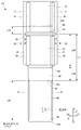
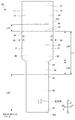
- FIG. 7 is a view of the plate material of the self-supporting display device 1 ⁇ / b> A according to the first embodiment as viewed from the back side.
- Each plate material of the self-supporting display device 1A is as follows.
- BF Corrugated cardboard
- Hinge 60-64 A resin sheet was used to attach to each plate with double-sided tape.
- the hinges 60 and 63 are also used as one sheet material.
- Hinge 65 As indicated by a two-dot chain line in the figure, the support plate 40 is provided with an ear 65a via a ruled line (folding line) functioning as a hinge, a half cut, or the like. The ear 65a was attached to the bottom plate 30.
- Hinge 66 Ears 66a (connection portions) are provided on the support plate 40 through ruled lines, half-cuts, and the like that function as hinges.
- the ear 66 a is affixed to the back surface of the first display board 10. Since FIG. 7 is a developed view, the ear 66a is not attached. By bonding the ear 66a to the hatched portion on the back surface of the first display panel 10, a portion related to the plate material of the self-supporting display device 1A is completed.
- FIG. 8 is a view of the plate material of the self-supporting display device 1B according to the first embodiment as viewed from the back side.
- the 1st display board 10, the 1st side board 11, the 2nd display board 20, the 2nd side board 21, the baseplate 30, and the support board 40 were integrally manufactured from the cardboard of 1 sheet.
- Hinges 60 to 65 Ruled lines that function as hinges, half-cuts, and the like are provided between the plate members.
- Hinge 66 Similarly to the self-supporting display device 1B, the support plate 40 is provided with an ear 66a (connecting portion) via a ruled line functioning as a hinge, a half cut or the like.
- the self-supporting display device 1B is made of cardboard, it is suitable for a small device (for example, the total height of the installed state is about 300 mm) from the viewpoint of strength design. Further, the eye direction was arranged in the vertical direction Z for the same reason as described above.
- FIG. 9 is a perspective view of a self-supporting display device 201 according to the second embodiment in a self-supporting state and a perspective view illustrating a holding structure.
- FIG. 9A is a perspective view of the self-supporting display device 201 in a self-supporting state (a diagram corresponding to FIG. 1).
- FIG. 9B is a perspective view for explaining a holding structure for the first display plate 10, the first side plate 11, the second display plate 20, and the second side plate 21 (a diagram corresponding to FIG. 3).
- the self-supporting display device 201 is provided with a clip 250 (holding member) instead of rubber.
- the clip 250 is a member formed of resin, metal or the like in a U-shaped cross section.
- the clip 250 is formed so that an urging force is exerted on the inside, and presses a member sandwiched on the inside.
- FIG. 9B the clip 250 is in a state where the first display board 10 and the second display board 20 are opened flat, and the first display board 10 and the second display board 20 and the first side plate. 11 and the second side plate 21 are inserted into the first side plate 11 and the second side plate 21 while the angle formed by the second side plate 21 is maintained at 90 °. Accordingly, the clip 250 can be held so that the first side plate 11 and the second side plate 21 are not folded, and can be held so that the first display plate 10 and the second display plate 20 are not folded.
- the self-supporting display device 201 can maintain the state in which the first display panel 10 side and the second display panel 20 are flattened and maintain the self-supporting state, as in the first embodiment. Note that folding of the self-supporting display device 201 is the same as in the first embodiment.
- the assembly of the self-supporting display device 201 is the same as that of the first embodiment except that the urging force by rubber does not work.
- FIG. 10 is a perspective view of the self-supporting display device 301 of the third embodiment in a self-supporting state (a diagram corresponding to FIG. 1).
- the first side plate 11 and the second side plate 21 are provided only on one side of the first display plate 10 and the second display plate 20.
- the opposite side of the rubber 350 from the first display panel 10 was hooked by providing a hook portion 324 on the back side of the second display panel 20. Even in such a configuration, the rubber 350 urges the first side plate 11 and the second side plate 21 inward, so that the self-supporting display device 301 has the same operations and effects as the first embodiment.
- FIG. 11 is a perspective view of the self-supporting display device 401 according to the fourth embodiment in a self-supporting state.
- the rubber 450 of the self-supporting display device 401 is hooked not on the second side plate 21 but on the notch 413 of the first side plate 11. Even in this case, the first side plate 11 is urged inward and applied to the support plate 40, whereby the state of rising by 90 ° with respect to the first display plate 10 is maintained. Further, since the first side plate 11 and the second side plate 21 are connected by the hinge 63 (see FIG. 3), the second side plate 21 is held in a state where it rises 90 ° with respect to the second display plate 20. .
- the self-supporting display device 401 flattens the first display plate 10 side and the second display plate 20 as in the first embodiment. Can be maintained in a self-supporting state. Note that the folding and assembling of the self-supporting display device 401 also operate in conjunction with each other because the first side plate 11 and the second side plate 21 are connected by the hinge 63 (see FIG. 3), and are the same as in the first embodiment. Can be done.
- FIG. 12 is a perspective view of the self-supporting display device 501 according to the fifth embodiment, as viewed from the back.
- the rubber 550 550-1, 550-2
- its mounting structure are changed from the first embodiment.
- the self-supporting display device 501 includes two rubbers 550 (550-1 and 550-2) that are elastic members.
- One end of the rubber 550-1 is hooked on the notch 523 of the second side plate 521 and connected to the second side plate 521.
- the other end of the rubber 550-1 is connected to the notch 543 of the support plate 540.
- the rubber 550-1 is attached so as to connect the inner surface of the second side plate 521 and the inner surface of the support plate 540 inside the self-supporting display device 501.
- the rubber 550-1 urges the second side plate 521 inward to raise the second side plate 521, as in the first embodiment.
- the self-supporting display device 501 can maintain the first display panel 10 and the second display panel 20 so as not to rotate and maintain the self-supporting function, as in the first embodiment.
- the rubber 550-2 and its mounting structure are symmetrical to and similar to the structure related to the rubber 550-1 (in FIG. 12, the rubber 550-2 inside the self-supporting display device 501 is shown (dotted line). ) Was omitted.)
- the self-supporting display device 501 is provided with the notch 543 of the support plate 540 and attached with the rubbers 550-1 and 550-2. -1,550-2 can be attached. This is because the positions of the notches 523 and 543 may be changed in accordance with the sizes of the rubbers 550-1 and 550-2. Further, even in a plurality of self-supporting display devices 501 having different sizes in the left-right direction X, if the positional relationship between the notch 523 of the second side plate 521 and the notch 543 of the support plate 540 is maintained, the second side plate 521 is moved inward. The magnitude of the energizing force becomes equal.
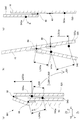
- FIG. 13 is a partial cross-sectional view of the self-supporting display device 501 of the fifth embodiment.
- FIG. 13A is a cross-sectional view of a state in which the self-supporting display device 501 is folded flat.
- FIG. 13B is a cross-sectional view of the self-supporting display device 501 in the open state.
- FIG. 13C is a cross-sectional view for explaining the movement of the point 543a in the process of changing from the state of FIG. 13A to the state of FIG. 13B.
- a point 523 a in FIG. 13 indicates the position of the notch 523 of the second side plate 521.
- a point 543a indicates the position of the notch 543 of the support plate 540.
- the movement of the points 523a and 543a when the self-supporting display device 501 is changed from the flat folded state to the open state will be described.
- the point 523a rotates around the hinge 60.
- the length L523a between the point 523a and the rotation center of the hinge 60 is maintained.
- the point 523a moves from the position of FIG. 13A to the position of FIG. In FIG. 13B, in actuality, since the second side plate 521 rises, the distance between the point 523a and the hinge 60 changes, but the amount of change is considered to be sufficiently small.
- the point 543a rotates around the hinge 66. For this reason, the length L543a between the point 543a and the rotation center of the hinge 66 is maintained. As a result, the point 543a moves from the position shown in FIG. 13A to the position shown in FIG. 13B.
- the movement of the point 543a when the self-supporting display device 501 changes from the state of FIG. 13A to the state of FIG. 13B will be described separately for rotation around the hinge 60 and rotation around the hinge 66. To do. Note that the self-standing display device 501 does not actually enter the state of FIG. 13C, but is shown for convenience in order to explain the movement of the point 543a.
- -Rotation around the hinge 60 From the state of FIG. 13A, the first display panel 10 and the second display panel 520 rotate approximately 180 ° around the hinge 60, and the point 543a moves away from the point 523a. (See arrow A), the state shown in FIG. -Rotation around the hinge 66 From the state of 13 (c), the first display panel 10 and the support plate 540 rotate around the hinge 66, and the point 543a moves so as to approach the point 523a (arrow B). reference).
- the points 523a and 543a satisfy the condition that the movement amount according to the arrow A is larger than the movement amount according to the arrow B.
- the length L501 between the points 523a and 543a is It becomes larger than the length L500 (L501> L500). That is, the length between the points 523a and 543a is increased.
- the arrangement of the points 523a and 543a satisfying the above conditions that is, the arrangement of the notches 523 and 543 can be appropriately set according to the arrangement of the hinges 60 and 66, etc.
- FIG. 13 is an example. Further, in FIG. 13A, for the same reason as in FIG. 5B, the first display panel 10 is not actually bent in the folded state.
- the rubber 550 when the self-supporting display device 501 is opened from the folded state, the rubber 550 has the second side plate 521 corresponding to the increased length between the points 523a and 543a in addition to the biasing force. Try to pull inward further. Thereby, the rubber 550 can raise the second side plate 521 more reliably. Even if the rubber stretches and a sufficient urging force cannot be obtained, the second side plate 521 is raised by the action of the length L500 becoming longer to the length L501 when opened. Can do.
- the self-supporting display device 501 reliably raises the second side plate 521, it is possible to improve the assembling reliability by being opened from the folded state.
- one end of the rubber 550 may be attached to the first side plate 11 with a notch instead of the second side plate 521. Further, the other end of the rubber 550 (550-1, 550-2) may be attached by providing a notch in the bottom plate 30 instead of the support plate 540. Even in this case, the effect described above can be obtained by setting the notch to be long when the open state is set.
- FIG. 14 is a perspective view of the self-supporting display device 601 according to the sixth embodiment in a self-supporting state.
- FIG. 14A is a perspective view seen from the front (front side Y1).
- FIG. 14B is a perspective view seen from the back (back side Y2).
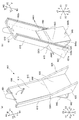
- FIG. 15 is an exploded perspective view of the self-supporting display device 601 according to the sixth embodiment as viewed from the back.
- the ruled lines are appropriately indicated by two-dot chain lines.
- the first display plate 610, the first side plate 611, the second display plate 620, and the second side plate 621 are formed of a single cardboard 602.
- Each connection portion between the plates is provided with a ruled line that is a folding line, and the ruled line functions as hinges 660, 662, and 663.
- the bottom plate 630 and the support plate 640 are formed of a single cardboard 603.
- Corrugated cardboard 603 is provided with hinges 664, 665, and 666 by ruled lines, similarly to corrugated cardboard 602.
- the corrugated cardboard 602 and the corrugated cardboard 603 are connected by an adhesive or the like using the margins 603a and 603b of the corrugated cardboard 603.
- the rubber mounting portion 623 of the second side plate 621 When viewed from the left-right direction X, the rubber mounting portion 623 of the second side plate 621 is disposed at a position intersecting the support plate 640. For this reason, the rubber mounting portion 623 is urged inward by the rubber 650 and abuts on the outer end surface 640 a of the support plate 640.
- the rubber attaching portion 623 refers to a portion of the second side plate 621 where the urging force by the rubber 650 acts greatly. In this embodiment, the rubber attachment portion 623 is a portion sandwiched between notches for attachment.
- the bottom plate 630 is attached such that the hinge 664 is on the upper side Z2 with respect to the lower end 620D of the second display plate 620 (see FIG. 16A).
- the bottom plate 630 has a notch 631.
- the margin 603b is bent at the hinge 664, the inner portion 632 of the notch 631 rises to the lower side Z1.
- the lower end of the inner part 632 is used as a position alignment when pasting to the second display panel 620 in the manufacturing process (see FIG. 16A). That is, the operator or the like may bond the bottom plate 630 and the second display plate 620 so that the lower end of the inner portion 632 and the lower end 620D of the second display plate 620 are aligned.
- the first side plate 611 includes a side reinforcement plate 615
- the second side plate 621 includes a foot plate 625 (foot portion)
- the rubber attachment portion 623 of the second side plate 621 includes a rubber attachment portion reinforcement plate 626.
- the self-supporting display device 601 includes a hook 680, a hanging strap 681, and hook-and-loop fasteners 682a and 682b.
- Each of the side reinforcing plate 615 and the foot plate 625 has a sufficient strength by folding one corrugated cardboard into two and overlapping them.
- the side reinforcing plate 615 is attached to the first side plate 611.
- the entire surface of the outer surface of the first side plate 611 and the inner surface of the side reinforcing plate 615 are bonded together with an adhesive or the like. When viewed from the left-right direction X, the outer shape of the side reinforcing plate 615 is equivalent to the first side plate 611.
- the foot plate 625 is affixed to the second side plate 621.
- the entire surface of the outer surface of the second side plate 621 and the inner surface of the foot plate 625 are bonded together with an adhesive or the like.
- the outer shape of the foot plate 625 is a quadrangle.
- the side 625U of the upper side Z2 and the side 625B of the back side Y2 of the foot plate 625 coincide with each side of the second side plate 621.
- the lower side 625D of the foot plate 625 has a form in which the lower side 621D of the second side plate 621 is extended to the front side Y1.
- the side 625F on the near side Y1 is an oblique side that reaches the near side Y1 as it reaches the lower side Z1 so as to be positioned on the near side Y1 with respect to the display surface of the second display panel 620 (the surface on the near side Y1). .
- a relief 625a of the rubber 650 is provided inside the foot plate 625 in a region corresponding to the rubber attachment portion 623. The rubber 650 protrudes outward from the side surface of the second side plate 621, so that the escape 625a escapes.
- the rubber mounting portion reinforcing plate 626 is a reinforcing plate for preventing the rubber mounting portion 623 from being bent by the urging force of the rubber 650.
- the rubber attachment portion reinforcing plate 626 is affixed inside the second side plate 621.
- the hook 680 is provided on the surface of the first display panel 610.
- the hook 680 is provided with a hinge at the base (not shown) and can be rotated to the upper side Z2.
- the hanging strap 681 is provided on the upper side Z ⁇ b> 2 of the first display board 610.
- the hook-and-loop fastener 682a is provided on the back surface of the first display plate 610
- the hook-and-loop fastener 682b is provided on the back surface of the support plate 640 (the surface on the back side Y2).
- FIG. 16 is a cross-sectional view of the self-supporting display device 601 of the sixth embodiment when viewed from the left-right direction X.
- FIG. 16A is a sectional view in a self-supporting state.
- FIG.16 (b) is sectional drawing of the form folded flat.
- FIG. 17 is a perspective view of a form in which the self-supporting display device 601 of the sixth embodiment is folded flat.
- the side reinforcing plate 615, the foot plate 625, and the like are indicated by dotted lines.
- the self-supporting display device 601 of this embodiment is mainly different from the above-described embodiment in the following points.
- the lower side 625D of the foot plate 625 has a form in which the lower side 621D of the second side plate 621 is extended to the front side Y1, and is grounded to the installation surface. Further, a hinge 665 between the support plate 640 and the bottom plate 630 is grounded to the installation surface. As a result, the grounding portion of the foot plate 625 is shaped to protrude to the near side Y1 with respect to the second display plate 620, and is strong against falling to the near side Y1.
- the self-supporting display device 601 can stably stand by itself even when a product, a sample, or the like is suspended from the hook 680. Further, in the self-supporting display device 601, the length L601 between the grounding portion on the near side Y1 and the installation portion on the far side Y2 is longer than that in the above-described embodiment, and stability against swinging can be improved.
- the front side Y1 of the second display panel 620 protrudes to the lower side Z1 from the bottom plate 630.
- the bottom plate 630 is grounded at the hinge 665 portion, the bottom plate 630 is disposed obliquely so as to reach the upper side Z2 as it reaches the near side Y1. Therefore, when the second side plate 621 is urged inward by the rubber 650, the inner surface 621a of the second side plate 621 is surely attached to the outer end surface 630a of the bottom plate 630, as shown in FIG. Abut.
- the rubber attaching portion 623 (more precisely, the rubber attaching portion reinforcing plate 626) of the second side plate 621 is urged inward by the rubber 650 and abuts on the outer end surface 640a of the support plate 640. .
- the second side plate 621 is restricted by the bottom plate 630 and the support plate 640 from rotating further inward. Therefore, the second side plate 621 can maintain a stable rising angle from the second display plate 620. Thereby, in relation to the above (2), the second side plate 621 can stably receive the end surface S601 of the lower side Z1 of the first side plate 611. Moreover, since the deformation
- the rubber attaching portion 623 of the second side plate 621 abuts against the outer end surface of the support plate 640 can also prevent the rubber attaching portion 623 from bending inward. For this reason, the self-supporting display device 601 can further increase the biasing force of the rubber 650.
- the first display panel 610 is not actually bent in the folded state for the same reason as in FIGS. 5 (b) and 13 (a).
- FIG. 17 is a perspective view of the self-supporting display device 601 according to the sixth embodiment in a folded state.
- the foot plate 625 is folded integrally with the second side plate 621 and disposed on the surfaces of the second display plate 620 and the bottom plate 630.
- the external shape in the surface direction (VW plane direction) of the self-supporting display device 601 in the folded state does not change regardless of the presence or absence of the foot plate 625. Thereby, the self-supporting display device 601 can be folded compactly.
- the first display plate 610 and the support plate 640 are maintained in the folded state by the hook-and-loop fasteners 682a and 682b. Further, as will be described later, in the folded state, the total length of the self-supporting display device 601 is equal to the length of the first display panel 610. For this reason, even if the self-supporting display device 601 is in the folded state, the first display panel 610 has a sufficient display area. Thereby, when the installation space cannot be secured in a store or the like, the self-supporting display device 601 can be posted on a wall or the like by the hanging strap 681.
- the dimension of the perpendicular direction Z seen from the side surface of each member in the folded state is set as follows.
- the self-supporting display device 601 can be folded to be approximately the same size as the length L610 of the first display panel 610 in the vertical direction. Accordingly, as described above, the self-supporting display device 601 can be hung so as to post the first display panel 610 even in the folded state.
- the self-supporting display device 601 may be provided with the rubber mounting portion 623 on the first side plate 611 as in the fourth embodiment (see FIG. 11). Even in this case, if the rubber mounting portion 623 is brought into contact with the support plate 640, the above-described effect can be obtained.
- the self-supporting display device 601 is low-cost because the main parts are formed of cardboard. In addition, the self-supporting display device 601 can improve strength.
- FIG. 18 is a cross-sectional view (a diagram corresponding to FIG. 16A) of the self-supporting display device 701 according to the seventh embodiment viewed from the left-right direction X.
- the bottom plate 730 and the support plate 740 are formed of different corrugated boards, and are bonded to each other at a portion constituting the hinge 765.
- the portion constituting the hinge 764 on the near side Y1 of the bottom plate 730 was bonded to the second display plate 720 so as to coincide with the lower end 740D of the second display plate 720.
- the lower part of the support plate 740 protrudes to the lower side Z1 from the bottom plate 730.
- the bottom plate 730 is inclined so as to reach the upper side Z2 as it reaches the back side Y2.
- the self-supporting display device 701 has the same effect as the sixth embodiment.
Landscapes
- Physics & Mathematics (AREA)
- General Physics & Mathematics (AREA)
- Engineering & Computer Science (AREA)
- Theoretical Computer Science (AREA)
- Devices For Indicating Variable Information By Combining Individual Elements (AREA)
- Road Signs Or Road Markings (AREA)
- Liquid Crystal (AREA)
Abstract
組み立てが簡単な自立式表示装置、自立式表示装置の板材を提供する。 自立式表示装置1は、第1表示板10の側辺に接続された第1側板11と、第1表示板10の下辺に接続された第2表示板20と、第1側板11及び第2表示板20に接続された第2側板21と、第2表示板20の下辺に接続された底板30と、一辺が底板30に接続され、他辺が第1表示板10の裏面に回転可能に接続された支持板40とを備え、縦断面形状において、平らに展開した第1表示板10及び第2表示板20と、底板30と、支持板40とが三角形70の各辺を形成して、開状態を維持する。
Description
本発明は、組み立て式の自立式表示装置、自立式表示装置の板材に関するものである。
従来、表示板を支持体に固定部材で固定して組み立てるディスプレイ装置があった(例えば特許文献1)。
しかし、従来のディスプレイ装置は、部品点数が多く、また、組み立ての工程が複雑であり、商店等での表示場所での組み立てが煩雑であった。
しかし、従来のディスプレイ装置は、部品点数が多く、また、組み立ての工程が複雑であり、商店等での表示場所での組み立てが煩雑であった。
本発明の課題は、組み立てが簡単な自立式表示装置、自立式表示装置の板材を提供することである。
本発明は、以下のような解決手段により、課題を解決する。なお、理解を容易にするために、本発明の実施形態に対応する符号を付して説明するが、これに限定されるものではない。また、符号を付して説明した構成は、適宜改良してもよく、また、少なくとも一部を他の構成物に代替してもよい。
・第1の発明は、第1表示板(10,610,710)と、前記第1表示板の側辺に回転可能に接続をされた第1側板(11,611)と、前記第1表示板の下辺に回転可能に接続をされた第2表示板(20,620,720)と、前記第1側板及び前記第2表示板に対してそれぞれ回転可能に接続をされた第2側板(21,521,621)と、前記第2表示板の下辺に回転可能に接続をされた底板(30,630,730)と、一辺が前記底板の辺のうち前記第2表示板とは反対側の辺に接続をされ、他辺が前記第1表示板の裏面に回転可能に接続をされた支持板(40,540,640,740)とを備え、前記第1側板が前記第1表示板に対して立ち上がった状態を保持され、又は前記第2側板が前記第2表示板に対して立ち上がった状態を保持することにより、かつ、前記第1側板及び前記第2側板間の上記接続(63,763)によって、前記第1側板及び前記第2側板がそれぞれ前記第1表示板及び前記第2表示板に対して立ち上がった状態を維持し、前記第1表示板及び前記第2表示板が平らに展開した状態を維持し、縦断面形状において、平らに展開した前記第1表示板及び前記第2表示板と、前記底板と、前記支持板とが三角形(70)の各辺を形成して、開状態を維持すること、を特徴とする自立式表示装置である。
・第2の発明は、第1の発明の自立式表示装置において、前記第1表示板(10,610,710)及び前記第1側板(11,611)は、前記第1表示板及び前記第1側板間の接続部で回転して平らに展開し、前記第2表示板(20,620,720)及び前記第2側板(21,521,621)は、前記第2表示板及び前記第2側板間の接続部で回転して平らに展開し、前記第1表示板及び前記第2表示板は、前記第1表示板及び前記第2表示板間の接続部で回転して折り畳まれ、前記第2側板及び前記底板(30,630,730)は、前記第2側板及び前記底板間の接続部で回転して折り畳まれ、前記底板及び前記支持板(40,540,640,740)は、前記底板及び前記支持板間の接続部で回転して折り畳まれ、前記支持板及び前記第1表示板は、前記支持板及び前記第1表示板間の接続部で回転して密着するように折り畳まれることによって、この自立式表示装置が全体として平らに折り畳まれること、を特徴とする自立式表示装置である。
・第3の発明は、第1又は第2の発明の自立式表示装置において、前記第1側板(11,611)が前記第1表示板(10,610,710)に対して立ち上がった状態を維持し、かつ、前記第2側板(21,521,621)が前記第2表示板(20,620,720)に対して立ち上がった状態を維持するように、前記第1側板又は前記第2側板を内側に付勢する付勢部材(50,350,550(550-1,550-2),650)を備えること、を特徴とする自立式表示装置である。
・第4の発明は、第1から第3のいずれかの発明の自立式表示装置において、付勢部材が前記第1側板(11)又は前記第2側板(21)を内側に付勢し、かつ、前記第1側板及び前記第2側板間の上記接続によって、前記第1側板及び前記第2側板が連動してそれぞれ前記第1表示板(10)及び前記第2表示板(20)に対して立ち上がった状態を維持し、前記第1側板及び前記第2側板の立ち上がりに連動して、前記第1表示板及び前記第2表示板が平らに自ら展開し、かつ、平らに展開した前記第1表示板及び前記第2表示板と、前記底板(30)と、前記支持板(40)とが折り畳み状態から前記開状態に自ら変形することを特徴とする自立式表示装置である。
・第5の発明は、第4の発明の自立式表示装置において、前記付勢部材は、一端が前記第1側板(11)又は前記第2側板(521)に接続され、他端が前記支持板(540)に対して内側の面から接続された伸縮部材(550(550-1,550-2))であること、を特徴とする自立式表示装置である。
・第6の発明は、第4の発明の自立式表示装置において、前記付勢部材は、一端が前記第2側板に接続され、他端が前記底板に対して内側の面から接続された伸縮部材であること、を特徴とする自立式表示装置である。
・第7の発明は、第5又は第6の発明の自立式表示装置において、前記付勢部材(650)の前記第1側板(611)又は前記第2側板(621)の取り付け部(623,626)は、内側に付勢されて、前記支持板(640)の外側端部に当接すること、を特徴とする自立式表示装置である。
・第8の発明は、第5から第7のいずれかの発明の自立式表示装置において、前記第2表示板(620)及び前記支持板(740)の少なくとも1つは、前記底板(630,763)よりも下側に突出しており、前記第2側板(621,721)は、前記底板の外側端部に当接すること、を特徴とする自立式表示装置である。
・第9の発明は、第1から第8のいずれかの発明の自立式表示装置において、前記第2側板(621,721)は、前記第2表示板(620,720)よりも手前側に突出した足部(625,725)を有すること、を特徴とする自立式表示装置である。
・第10の発明は、第1から第9のいずれかの発明の自立式表示装置において、前記第2表示板(20)の長さと、前記底板(30)の長さとを加算した長さをL1とし、前記支持板(40)の長さと、前記支持板及び前記第1表示板(10)の接続部と前記第1表示板及び前記第2表示板の接続部との長さとを加算した長さをL2とした場合に、L1=L2が成り立つこと、を特徴とする自立式表示装置である。
・第11の発明は、第1から第9のいずれかの発明の自立式表示装置において、前記第1表示板(610,710)及び前記第2表示板(620,720)の接続部(660,760)と、前記底板(630,730)及び前記支持板(640,740)の接続部(664,764)との間の長さをL61とし、前記第1表示板及び前記第2表示板の接続部(660)と、前記第1表示板及び前記支持板の接続部(666,766)との長さL62とし、前記第1表示板及び前記支持板の接続部と、前記支持板及び前記底板の接続部との長さL63とした場合に、L61=L62+L63が成り立つこと、を特徴とする自立式表示装置である。
・第2の発明は、第1の発明の自立式表示装置において、前記第1表示板(10,610,710)及び前記第1側板(11,611)は、前記第1表示板及び前記第1側板間の接続部で回転して平らに展開し、前記第2表示板(20,620,720)及び前記第2側板(21,521,621)は、前記第2表示板及び前記第2側板間の接続部で回転して平らに展開し、前記第1表示板及び前記第2表示板は、前記第1表示板及び前記第2表示板間の接続部で回転して折り畳まれ、前記第2側板及び前記底板(30,630,730)は、前記第2側板及び前記底板間の接続部で回転して折り畳まれ、前記底板及び前記支持板(40,540,640,740)は、前記底板及び前記支持板間の接続部で回転して折り畳まれ、前記支持板及び前記第1表示板は、前記支持板及び前記第1表示板間の接続部で回転して密着するように折り畳まれることによって、この自立式表示装置が全体として平らに折り畳まれること、を特徴とする自立式表示装置である。
・第3の発明は、第1又は第2の発明の自立式表示装置において、前記第1側板(11,611)が前記第1表示板(10,610,710)に対して立ち上がった状態を維持し、かつ、前記第2側板(21,521,621)が前記第2表示板(20,620,720)に対して立ち上がった状態を維持するように、前記第1側板又は前記第2側板を内側に付勢する付勢部材(50,350,550(550-1,550-2),650)を備えること、を特徴とする自立式表示装置である。
・第4の発明は、第1から第3のいずれかの発明の自立式表示装置において、付勢部材が前記第1側板(11)又は前記第2側板(21)を内側に付勢し、かつ、前記第1側板及び前記第2側板間の上記接続によって、前記第1側板及び前記第2側板が連動してそれぞれ前記第1表示板(10)及び前記第2表示板(20)に対して立ち上がった状態を維持し、前記第1側板及び前記第2側板の立ち上がりに連動して、前記第1表示板及び前記第2表示板が平らに自ら展開し、かつ、平らに展開した前記第1表示板及び前記第2表示板と、前記底板(30)と、前記支持板(40)とが折り畳み状態から前記開状態に自ら変形することを特徴とする自立式表示装置である。
・第5の発明は、第4の発明の自立式表示装置において、前記付勢部材は、一端が前記第1側板(11)又は前記第2側板(521)に接続され、他端が前記支持板(540)に対して内側の面から接続された伸縮部材(550(550-1,550-2))であること、を特徴とする自立式表示装置である。
・第6の発明は、第4の発明の自立式表示装置において、前記付勢部材は、一端が前記第2側板に接続され、他端が前記底板に対して内側の面から接続された伸縮部材であること、を特徴とする自立式表示装置である。
・第7の発明は、第5又は第6の発明の自立式表示装置において、前記付勢部材(650)の前記第1側板(611)又は前記第2側板(621)の取り付け部(623,626)は、内側に付勢されて、前記支持板(640)の外側端部に当接すること、を特徴とする自立式表示装置である。
・第8の発明は、第5から第7のいずれかの発明の自立式表示装置において、前記第2表示板(620)及び前記支持板(740)の少なくとも1つは、前記底板(630,763)よりも下側に突出しており、前記第2側板(621,721)は、前記底板の外側端部に当接すること、を特徴とする自立式表示装置である。
・第9の発明は、第1から第8のいずれかの発明の自立式表示装置において、前記第2側板(621,721)は、前記第2表示板(620,720)よりも手前側に突出した足部(625,725)を有すること、を特徴とする自立式表示装置である。
・第10の発明は、第1から第9のいずれかの発明の自立式表示装置において、前記第2表示板(20)の長さと、前記底板(30)の長さとを加算した長さをL1とし、前記支持板(40)の長さと、前記支持板及び前記第1表示板(10)の接続部と前記第1表示板及び前記第2表示板の接続部との長さとを加算した長さをL2とした場合に、L1=L2が成り立つこと、を特徴とする自立式表示装置である。
・第11の発明は、第1から第9のいずれかの発明の自立式表示装置において、前記第1表示板(610,710)及び前記第2表示板(620,720)の接続部(660,760)と、前記底板(630,730)及び前記支持板(640,740)の接続部(664,764)との間の長さをL61とし、前記第1表示板及び前記第2表示板の接続部(660)と、前記第1表示板及び前記支持板の接続部(666,766)との長さL62とし、前記第1表示板及び前記支持板の接続部と、前記支持板及び前記底板の接続部との長さL63とした場合に、L61=L62+L63が成り立つこと、を特徴とする自立式表示装置である。
・第12の発明は、第1から第11のいずれかの発明の自立式表示装置に加工される板材であって、前記支持板(40,540,640,740)は、前記他辺が前記第2表示板(20,620,720)の裏面から分離した状態であり、前記支持板が回転可能に、前記他辺を前記第2表示板の裏面に対して接続する接続部(66a)を備えること、を特徴とする板材である。
本発明によれば、組み立てが簡単な自立式表示装置を提供できる。
(第1実施形態)
以下、図面等を参照して、本発明の第1実施形態について説明する。
図1は、第1実施形態の自立式表示装置1の自立状態の斜視図である。
図2は、第1実施形態の自立式表示装置1の自立状態の断面図、背面図である。
図2(a)は、自立式表示装置1の横断面図(図1の2a-2a部断面図)である。
図2(b)は、第1表示板10、第1側板11、第2表示板20、第2側板21の接続部分を裏面から見た図である。なお、図2(b)では、支持板40の図示は、省略した。
図2(c)は、自立式表示装置1の縦断面図(図1の2c-2c部断面図)である。
図3は、第1実施形態の第1表示板10、第1側板11、第2表示板20、第2側板21の保持構造を説明する斜視図である。
実施形態では、自立式表示装置1を鉛直方向Zに自立させて設置した場合の左右方向をX、奥行方向をYとして説明する。また、各図の対応を明確にするために、設置状態において、第1表示板10及び第2表示板20の面方向のうち鉛直方向を座標W、第1表示板10及び第2表示板20の表面の法線方向を座標Vとして、VW座標系を設けて図示した。
なお、説明の便宜上、図1の状態を基準に、手前側Y1を表、奥側Y2を裏として適宜説明する。
以下、図面等を参照して、本発明の第1実施形態について説明する。
図1は、第1実施形態の自立式表示装置1の自立状態の斜視図である。
図2は、第1実施形態の自立式表示装置1の自立状態の断面図、背面図である。
図2(a)は、自立式表示装置1の横断面図(図1の2a-2a部断面図)である。
図2(b)は、第1表示板10、第1側板11、第2表示板20、第2側板21の接続部分を裏面から見た図である。なお、図2(b)では、支持板40の図示は、省略した。
図2(c)は、自立式表示装置1の縦断面図(図1の2c-2c部断面図)である。
図3は、第1実施形態の第1表示板10、第1側板11、第2表示板20、第2側板21の保持構造を説明する斜視図である。
実施形態では、自立式表示装置1を鉛直方向Zに自立させて設置した場合の左右方向をX、奥行方向をYとして説明する。また、各図の対応を明確にするために、設置状態において、第1表示板10及び第2表示板20の面方向のうち鉛直方向を座標W、第1表示板10及び第2表示板20の表面の法線方向を座標Vとして、VW座標系を設けて図示した。
なお、説明の便宜上、図1の状態を基準に、手前側Y1を表、奥側Y2を裏として適宜説明する。
(利用時の形態)
自立式表示装置1の利用時の形態について説明する。
図1、図2に示すように、自立式表示装置1は、第1表示板10、第2表示板20の表面に、例えば、印刷等によって表示が設けられている。自立式表示装置1の用途は、例えば、広告等の表示(図示せず)を設け、店舗の店頭にする看板等である。自立式表示装置1の全高は、例えば、300~2000mm程度である。なお、自立式表示装置1の用途、大きさは、これに限定されない。
自立式表示装置1は、第1表示板10、第1側板11、第2表示板20、第2側板21、底板30、支持板40、ゴム50(付勢部材)、ヒンジ60~66を備える。
第1表示板10、第1側板11、第2表示板20、第2側板21、底板30、支持板40は、紙材、樹脂板や、発泡樹脂板に紙材を貼り合わせた部材等により形成される。各板材は、自立式表示装置1が自立して設置できる程度に、十分な強度を有する。
ヒンジ60~66は、各板材間を回転可能に接続する板材である。ヒンジ60~66は、紙材、樹脂シートに接着テープを貼り張り合わせた部材等により形成され、各板材に接着できるようになっている。
自立式表示装置1の利用時の形態について説明する。
図1、図2に示すように、自立式表示装置1は、第1表示板10、第2表示板20の表面に、例えば、印刷等によって表示が設けられている。自立式表示装置1の用途は、例えば、広告等の表示(図示せず)を設け、店舗の店頭にする看板等である。自立式表示装置1の全高は、例えば、300~2000mm程度である。なお、自立式表示装置1の用途、大きさは、これに限定されない。
自立式表示装置1は、第1表示板10、第1側板11、第2表示板20、第2側板21、底板30、支持板40、ゴム50(付勢部材)、ヒンジ60~66を備える。
第1表示板10、第1側板11、第2表示板20、第2側板21、底板30、支持板40は、紙材、樹脂板や、発泡樹脂板に紙材を貼り合わせた部材等により形成される。各板材は、自立式表示装置1が自立して設置できる程度に、十分な強度を有する。
ヒンジ60~66は、各板材間を回転可能に接続する板材である。ヒンジ60~66は、紙材、樹脂シートに接着テープを貼り張り合わせた部材等により形成され、各板材に接着できるようになっている。
図1に示すように、第1表示板10は、上段に配置された表示板である。
第1側板11は、第1表示板10の左右の側辺にそれぞれ連設されている。
第2表示板20は、第1表示板10の下段に連設された表示板である。
第2側板21は、第2表示板20の左右の側辺にそれぞれ連設されている。
底板30は、第2側板21の下辺に連設されている。
支持板40は、底板30に奥側Y2の辺に連設されている。また、支持板40は、底板30側とは反対側の辺が、第1表示板10の裏面に取り付けられている。
ゴム50は、第2側板21を左右方向Xの内側に付勢するゴムバンド(輪ゴム)である。ゴム50は、第2側板21の切り欠き23に引っ掛けられている。ゴム50は、左右方向Xにおいて、2つの第2側板21を引き寄せるように付勢して、伸び状態から縮み状態に付勢する。
なお、付勢部材は、ゴム50に限定されず、第2側板21を内側に付勢する部材であれば、いずれの形態でもよい。例えば、付勢部材は、90°に折り曲げた板バネ等を、第2表示板20、第2側板21の内側コーナ部分に貼付したものであってもよい。
第1側板11は、第1表示板10の左右の側辺にそれぞれ連設されている。
第2表示板20は、第1表示板10の下段に連設された表示板である。
第2側板21は、第2表示板20の左右の側辺にそれぞれ連設されている。
底板30は、第2側板21の下辺に連設されている。
支持板40は、底板30に奥側Y2の辺に連設されている。また、支持板40は、底板30側とは反対側の辺が、第1表示板10の裏面に取り付けられている。
ゴム50は、第2側板21を左右方向Xの内側に付勢するゴムバンド(輪ゴム)である。ゴム50は、第2側板21の切り欠き23に引っ掛けられている。ゴム50は、左右方向Xにおいて、2つの第2側板21を引き寄せるように付勢して、伸び状態から縮み状態に付勢する。
なお、付勢部材は、ゴム50に限定されず、第2側板21を内側に付勢する部材であれば、いずれの形態でもよい。例えば、付勢部材は、90°に折り曲げた板バネ等を、第2表示板20、第2側板21の内側コーナ部分に貼付したものであってもよい。
図2に示すように、第1表示板10及び第2表示板20間は、ヒンジ60によって回転可能に接続されている。
第1表示板10及び第1側板11間は、ヒンジ61によって回転可能に接続されている。
第2側板21及び第2表示板20間は、ヒンジ62によって回転可能に接続されている。また、第1側板11及び第2側板21間は、ヒンジ63によって回転可能に接続されている。
第2表示板20及び底板30間は、ヒンジ64によって回転可能に接続されている。
底板30及び支持板40間は、ヒンジ65によって回転可能に接続されている。
支持板40は、第1表示板10の裏面に対して、ヒンジ66によって回転可能に接続されている。
このように、自立式表示装置1は、各板部材がヒンジ60~66によって接続されて一体的に形成される。このため、自立式表示装置1は、ヒンジ60~66、ゴム50が組み込まれた後には、新たな部品を組み込む必要がなく、簡単に組み立てできる。
第1表示板10及び第1側板11間は、ヒンジ61によって回転可能に接続されている。
第2側板21及び第2表示板20間は、ヒンジ62によって回転可能に接続されている。また、第1側板11及び第2側板21間は、ヒンジ63によって回転可能に接続されている。
第2表示板20及び底板30間は、ヒンジ64によって回転可能に接続されている。
底板30及び支持板40間は、ヒンジ65によって回転可能に接続されている。
支持板40は、第1表示板10の裏面に対して、ヒンジ66によって回転可能に接続されている。
このように、自立式表示装置1は、各板部材がヒンジ60~66によって接続されて一体的に形成される。このため、自立式表示装置1は、ヒンジ60~66、ゴム50が組み込まれた後には、新たな部品を組み込む必要がなく、簡単に組み立てできる。
(自立構造)
自立式表示装置1の自立構造について説明する。
図2(c)に示すように、第1表示板10(ヒンジ60及びヒンジ66間の部分)及び第2表示板20と、底板30と、支持板40とは、三角形70の各辺を形成して、開状態となる。ここで、第1表示板10及び第2表示板20が、ヒンジ60で回転してしまえば、この三角形70が四角形71(図5(a)参照)に変形して、自立できなくなってしまう。この場合には、自立式表示装置1は、折り畳まれてしまう。
そこで、自立式表示装置1は、以下の機能により、第1表示板10及び第2表示板20が回転しないように保持して、自立を維持できるようになっている。
自立式表示装置1の自立構造について説明する。
図2(c)に示すように、第1表示板10(ヒンジ60及びヒンジ66間の部分)及び第2表示板20と、底板30と、支持板40とは、三角形70の各辺を形成して、開状態となる。ここで、第1表示板10及び第2表示板20が、ヒンジ60で回転してしまえば、この三角形70が四角形71(図5(a)参照)に変形して、自立できなくなってしまう。この場合には、自立式表示装置1は、折り畳まれてしまう。
そこで、自立式表示装置1は、以下の機能により、第1表示板10及び第2表示板20が回転しないように保持して、自立を維持できるようになっている。
(1)図3に示すように、ゴム50は、第2側板21を内側に付勢する。
(2)第1側板11及び第2側板21間は、ヒンジ63によって接続されているので、第1側板11は、第2側板21に連動して内側に付勢される。これにより、第1側板11は、支持板40に当て付けられ、第1表示板10から立ち上がった状態が維持され、また、第1側板11及び第1表示板10がなす角は、90°に保持される。同時に、第1側板11及び第2側板21間は、ヒンジ63によって接続されているので、第2側板21は、第2表示板20から立ち上がった状態が維持され、また、第2側板21及び第2表示板20がなす角は、90°に保持される。
このように、ゴム50の付勢力及び支持板40のストッパ機能によって、第1側板11が第1表示板10に対して90°に立ち上がった状態を維持され、かつ、第2側板21が第2表示板20に対して90°に立ち上がった状態を維持される。
なお、支持板40は、ストッパ機能と、後述する倒れ抑制の機能とを兼用するように、構成されている。
(3)第1側板11及び第1表示板10がなす角が90°に保持され、かつ、第2側板21及び第2表示板20がなす角が90°に保持される。このため、第1側板11及び第2側板21が一体となってつっぱり、第1表示板10側及び第2表示板20は、ヒンジ60回りに回転しないように規制される。これにより、第1表示板10側及び第2表示板20は、平ら(180°)に展開した状態が維持される。
(4)第1側板11の下側Z1の端面と、第2側板21の上側Z2の端面とは、面接触する(図1に示す接触面S1参照)。ここで、例えば、第1側板11の上端から下側Z1に力が加わった場合(図2に示す矢印F1参照)等には、第1表示板11は、ヒンジ60回りに奥側Y2に回転するように力が加わる。この場合、面接触S1によって、第1表示板11は、この回転が抑制される。
以上により、第1表示板10及び第2表示板20と、底板30と、支持板40とは、開状態である三角形70(図2(c)参照)を維持し、自立式表示装置1は、底板30を設置して、支持板40によって支持されて、自立した状態を維持できる。
(2)第1側板11及び第2側板21間は、ヒンジ63によって接続されているので、第1側板11は、第2側板21に連動して内側に付勢される。これにより、第1側板11は、支持板40に当て付けられ、第1表示板10から立ち上がった状態が維持され、また、第1側板11及び第1表示板10がなす角は、90°に保持される。同時に、第1側板11及び第2側板21間は、ヒンジ63によって接続されているので、第2側板21は、第2表示板20から立ち上がった状態が維持され、また、第2側板21及び第2表示板20がなす角は、90°に保持される。
このように、ゴム50の付勢力及び支持板40のストッパ機能によって、第1側板11が第1表示板10に対して90°に立ち上がった状態を維持され、かつ、第2側板21が第2表示板20に対して90°に立ち上がった状態を維持される。
なお、支持板40は、ストッパ機能と、後述する倒れ抑制の機能とを兼用するように、構成されている。
(3)第1側板11及び第1表示板10がなす角が90°に保持され、かつ、第2側板21及び第2表示板20がなす角が90°に保持される。このため、第1側板11及び第2側板21が一体となってつっぱり、第1表示板10側及び第2表示板20は、ヒンジ60回りに回転しないように規制される。これにより、第1表示板10側及び第2表示板20は、平ら(180°)に展開した状態が維持される。
(4)第1側板11の下側Z1の端面と、第2側板21の上側Z2の端面とは、面接触する(図1に示す接触面S1参照)。ここで、例えば、第1側板11の上端から下側Z1に力が加わった場合(図2に示す矢印F1参照)等には、第1表示板11は、ヒンジ60回りに奥側Y2に回転するように力が加わる。この場合、面接触S1によって、第1表示板11は、この回転が抑制される。
以上により、第1表示板10及び第2表示板20と、底板30と、支持板40とは、開状態である三角形70(図2(c)参照)を維持し、自立式表示装置1は、底板30を設置して、支持板40によって支持されて、自立した状態を維持できる。
(自立状態からの折り畳み状態への折り畳み)
自立式表示装置1の折り畳みについて説明する。
図4は、第1実施形態の自立式表示装置1の折り畳み作業を説明する斜視図である。
図4(a)は、自立式表示装置1全体の斜視図である。
図4(b)は、自立式表示装置1の背面を拡大して示す斜視図である。
図5は、第1実施形態の自立式表示装置1の折り畳み形態を説明する縦断面図である。
図5(a)は、自立式表示装置1の折り畳み動作を説明する図である。
図5(b)は、自立式表示装置1が平らに折り畳まれた形態を説明する図である。
なお、図5(b)は、断面形状を明確にするために、断面部分にハッチングを付した。
図6は、第1実施形態の自立式表示装置1が平らに折り畳まれた形態を説明する斜視図である。
前述したように、第1側板11及び第2側板21が第1表示板10及び第2表示板20から立ち上がった状態が保持されることによって、自立式表示装置1は、自立した状態を維持する。このため、作業者(自立式表示装置1が設置された店舗の店員等)は、以下のように、第1側板11及び第2側板21を立ち上がった状態から折り曲げるように回転すれば、自立式表示装置1を折り畳むことができる。
(1)図4(a)に示すように、作業者は、第1側板11を外側に広げるように、ヒンジ61回りに回転する(矢印A参照)。第1側板11及び第2側板21間は、ヒンジ63によって接続されているので、第1側板11が回転すると、第2側板21が連動して回転する。なお、図4(a)は、第1側板11を回転するように図示しているが、第2側板21を回転しても、同様に、第1側板11を連動して回転することができる。
図4(b)に示すように、第1側板11及び第2側板21が、第1表示板10及び第2表示板20に対して平らになるまで回転するとつっぱりの機能がなくなり、第1表示板10及び第2表示板20は、ヒンジ60回りに回転して、折り畳まれる(矢印B参照)。
(2)図5(a)に示すように、第1表示板10及び第2表示板20の回転に応じて、第2側板21及び底板30は、ヒンジ64回りに回転して折り畳まれる。また、底板30及び支持板40は、ヒンジ65回りに回転して折り畳まれる。支持板40及び第1表示板10は、ヒンジ66回りに回転して折り畳まれる。
これにより、第1表示板10及び第2表示板20と、底板30と、支持板40とは、開状態である三角形70の形態が維持できなくなり、四角形71へと変形する。
(3)図5(b)、図6に示すように、最終的には、支持板40及び第1表示板10が、密着するように折り畳まれた閉状態になり(図5(b)には、各部材を明確にするために、各部材間に隙間を有するように図示した)、自立式表示装置1全体が、平らになるまで折り畳むことができる。図5(b)においては、第1表示板10がヒンジ66付近で折れ曲がっているように表現されているが、断面図の説明上このように表現されているものであり、むろん実際には折り畳み状態において第1表示板10は折れ曲がるわけではない。
なお、このように平らになる寸法設定については、後述する。
このように、自立式表示装置1は、全体が平らに折り畳み可能であるので、収納時、運搬時にかさばらず、取り扱いが容易である。
自立式表示装置1の折り畳みについて説明する。
図4は、第1実施形態の自立式表示装置1の折り畳み作業を説明する斜視図である。
図4(a)は、自立式表示装置1全体の斜視図である。
図4(b)は、自立式表示装置1の背面を拡大して示す斜視図である。
図5は、第1実施形態の自立式表示装置1の折り畳み形態を説明する縦断面図である。
図5(a)は、自立式表示装置1の折り畳み動作を説明する図である。
図5(b)は、自立式表示装置1が平らに折り畳まれた形態を説明する図である。
なお、図5(b)は、断面形状を明確にするために、断面部分にハッチングを付した。
図6は、第1実施形態の自立式表示装置1が平らに折り畳まれた形態を説明する斜視図である。
前述したように、第1側板11及び第2側板21が第1表示板10及び第2表示板20から立ち上がった状態が保持されることによって、自立式表示装置1は、自立した状態を維持する。このため、作業者(自立式表示装置1が設置された店舗の店員等)は、以下のように、第1側板11及び第2側板21を立ち上がった状態から折り曲げるように回転すれば、自立式表示装置1を折り畳むことができる。
(1)図4(a)に示すように、作業者は、第1側板11を外側に広げるように、ヒンジ61回りに回転する(矢印A参照)。第1側板11及び第2側板21間は、ヒンジ63によって接続されているので、第1側板11が回転すると、第2側板21が連動して回転する。なお、図4(a)は、第1側板11を回転するように図示しているが、第2側板21を回転しても、同様に、第1側板11を連動して回転することができる。
図4(b)に示すように、第1側板11及び第2側板21が、第1表示板10及び第2表示板20に対して平らになるまで回転するとつっぱりの機能がなくなり、第1表示板10及び第2表示板20は、ヒンジ60回りに回転して、折り畳まれる(矢印B参照)。
(2)図5(a)に示すように、第1表示板10及び第2表示板20の回転に応じて、第2側板21及び底板30は、ヒンジ64回りに回転して折り畳まれる。また、底板30及び支持板40は、ヒンジ65回りに回転して折り畳まれる。支持板40及び第1表示板10は、ヒンジ66回りに回転して折り畳まれる。
これにより、第1表示板10及び第2表示板20と、底板30と、支持板40とは、開状態である三角形70の形態が維持できなくなり、四角形71へと変形する。
(3)図5(b)、図6に示すように、最終的には、支持板40及び第1表示板10が、密着するように折り畳まれた閉状態になり(図5(b)には、各部材を明確にするために、各部材間に隙間を有するように図示した)、自立式表示装置1全体が、平らになるまで折り畳むことができる。図5(b)においては、第1表示板10がヒンジ66付近で折れ曲がっているように表現されているが、断面図の説明上このように表現されているものであり、むろん実際には折り畳み状態において第1表示板10は折れ曲がるわけではない。
なお、このように平らになる寸法設定については、後述する。
このように、自立式表示装置1は、全体が平らに折り畳み可能であるので、収納時、運搬時にかさばらず、取り扱いが容易である。
(折り畳み状態から自立状態への組み立て)
自立式表示装置1の組み立てについて説明する。
自立式表示装置1の組み立ては、作業者が上記折り畳みとは逆の工程に従う。
(1)図6に示すように、作業者は、自立式表示装置1が折り畳まれている状態から、第1表示板10及び第1側板11と、第2表示板20及び第2側板21とを展開する(矢印C参照)。
(2)第1表示板10及び第2表示板20が90°程度まで展開されると、ゴム50の付勢力が有効に働くようになり、第2側板21が自ら立ち上がろうとする。また、第1側板11及び第2側板21は、ヒンジ63で接続されているので、第2側板21に連動して、第1側板11が第1表示板10から自ら立ち上がる(図3参照)。
自立式表示装置1の組み立てについて説明する。
自立式表示装置1の組み立ては、作業者が上記折り畳みとは逆の工程に従う。
(1)図6に示すように、作業者は、自立式表示装置1が折り畳まれている状態から、第1表示板10及び第1側板11と、第2表示板20及び第2側板21とを展開する(矢印C参照)。
(2)第1表示板10及び第2表示板20が90°程度まで展開されると、ゴム50の付勢力が有効に働くようになり、第2側板21が自ら立ち上がろうとする。また、第1側板11及び第2側板21は、ヒンジ63で接続されているので、第2側板21に連動して、第1側板11が第1表示板10から自ら立ち上がる(図3参照)。
(3)第1側板11及び第2側板21の立ち上がりに連動して、第1表示板10及び第1側板11と、第2表示板20及び第2側板21とが平らに自ら展開することで(図3参照)、第1表示板10及び第2表示板20と、底板30と、支持板40とは、閉状態から四角形71へと変形する(図5(a)参照)。
(4)ゴム50の付勢力により、第1表示板10及び第1側板11と、第2表示板20及び第2側板21とが平らになるまで開くと、第1側板11及び第2側板21が支持板40に当て付いて、第1表示板10及び第2表示板20から90°に立ち上がった状態を維持する(図3参照)。そして、第1表示板10及び第2表示板20と、底板30と、支持板40とは、開状態である三角形70を形成して(図2(b)参照)、自立式表示装置1は、自立した状態になり組み立てが完了する。
(4)ゴム50の付勢力により、第1表示板10及び第1側板11と、第2表示板20及び第2側板21とが平らになるまで開くと、第1側板11及び第2側板21が支持板40に当て付いて、第1表示板10及び第2表示板20から90°に立ち上がった状態を維持する(図3参照)。そして、第1表示板10及び第2表示板20と、底板30と、支持板40とは、開状態である三角形70を形成して(図2(b)参照)、自立式表示装置1は、自立した状態になり組み立てが完了する。
このように、自立式表示装置1は、ゴム50の付勢力により、自ら組み立とうとする。従って、作業者は、第1表示板10及び第1側板11と、第2表示板20及び第2側板21とを90°程度まで展開する以外は、力を殆んど加える必要がなく、かつ、前述したように新たに部品を組み込む必要がないので、商店の店頭等でも簡単に組み立てることができる。
(寸法設定)
図5(b)に示すように、折り畳み状態において、各部材の側面から見た鉛直方向Zの寸法は、以下のように設定されている。
第2表示板20の長さ:長さL20
底板30の長さ:長さL30
支持板40の長さ:長さL40
ヒンジ66(支持板40及び第1表示板10の接続部)とヒンジ60(第1表示板10及び第2表示板20の接続部)との間の長さ:長さL10
長さL1=L20+L30
長さL2=L40+L10
とした場合に、
長さL1=長さL2
が成り立つように、寸法設定されている。このように、自立式表示装置1は、ヒンジ60及びヒンジ65間において、表側の部材、裏側の部材が等長に設定されているので、閉状態では、平らに折り畳むことができる。また、開状態では、三角形70が形成され、かつ、第1表示板10及び第2表示板20を平らに展開し、自立できる。
なお、長さL10については、各板材、各ヒンジの厚さは十分に薄いので、長さL10=長さL10aとしてもよい。
図5(b)に示すように、折り畳み状態において、各部材の側面から見た鉛直方向Zの寸法は、以下のように設定されている。
第2表示板20の長さ:長さL20
底板30の長さ:長さL30
支持板40の長さ:長さL40
ヒンジ66(支持板40及び第1表示板10の接続部)とヒンジ60(第1表示板10及び第2表示板20の接続部)との間の長さ:長さL10
長さL1=L20+L30
長さL2=L40+L10
とした場合に、
長さL1=長さL2
が成り立つように、寸法設定されている。このように、自立式表示装置1は、ヒンジ60及びヒンジ65間において、表側の部材、裏側の部材が等長に設定されているので、閉状態では、平らに折り畳むことができる。また、開状態では、三角形70が形成され、かつ、第1表示板10及び第2表示板20を平らに展開し、自立できる。
なお、長さL10については、各板材、各ヒンジの厚さは十分に薄いので、長さL10=長さL10aとしてもよい。
以上説明したように、自立式表示装置1は、コンパクトに折り畳みでき、また、部品点数が少なく、簡単に組み立てることができる。
(展開図の例)
自立式表示装置1(自立式表示装置1A,1B)に加工される板材を説明する。自立式表示装置1の板材は、自立式表示装置1を平らに展開した形状である。なお、自立式表示装置1A,1Bの形態は、一例であって、種々変更できる。
図7は、第1実施形態の自立式表示装置1Aの板材を裏面側から見た図である。
自立式表示装置1Aの各板材は、以下の通りである。
第1表示板10、第1側板11、第2表示板20、第2側板21、底板30:エスレン発泡ボード(厚さt=5mm)の表裏に樹脂シートを貼付した。意匠性をよくし、強度が高い材料を用いた。
支持板40:段ボール(BF)を用いた。背面に配置されるので、意匠性よりも低コストを重視して材料を選択した。左右に耳41を設け、内側に折り曲げて、強度を向上した。なお、強度が不足する場合には、段ボールを2枚重ねて、補強してもよい。
また、支持板40は、目方向が鉛直方向Zになるように配置した。この理由は、自立状態等において、各板材には、鉛直方向Zに大きい力が加わる場面が多いので、この方向の強度を向上して、支持板40の屈曲を抑制するためである。
ヒンジ60~64:樹脂シートを用いて、両面テープで各板材に貼付した。ヒンジ60,63は、1枚のシート材で兼用した。
ヒンジ65:図中2点鎖線で示すように、支持板40に、ヒンジとして機能する罫線(折込線)、ハーフカット等を介して、耳65aを設けた。耳65aは、底板30に貼付した。
ヒンジ66:支持板40に、ヒンジとして機能する罫線、ハーフカット等を介して、耳66a(接続部)を設けた。耳66aは、第1表示板10の裏面に貼付した。なお、図7は、展開図であるので、耳66aが貼付されていない状態である。この耳66aを第1表示板10の裏面のハッチング部分に接着することで、自立式表示装置1Aのうち板材に係る部分が完成する。
自立式表示装置1(自立式表示装置1A,1B)に加工される板材を説明する。自立式表示装置1の板材は、自立式表示装置1を平らに展開した形状である。なお、自立式表示装置1A,1Bの形態は、一例であって、種々変更できる。
図7は、第1実施形態の自立式表示装置1Aの板材を裏面側から見た図である。
自立式表示装置1Aの各板材は、以下の通りである。
第1表示板10、第1側板11、第2表示板20、第2側板21、底板30:エスレン発泡ボード(厚さt=5mm)の表裏に樹脂シートを貼付した。意匠性をよくし、強度が高い材料を用いた。
支持板40:段ボール(BF)を用いた。背面に配置されるので、意匠性よりも低コストを重視して材料を選択した。左右に耳41を設け、内側に折り曲げて、強度を向上した。なお、強度が不足する場合には、段ボールを2枚重ねて、補強してもよい。
また、支持板40は、目方向が鉛直方向Zになるように配置した。この理由は、自立状態等において、各板材には、鉛直方向Zに大きい力が加わる場面が多いので、この方向の強度を向上して、支持板40の屈曲を抑制するためである。
ヒンジ60~64:樹脂シートを用いて、両面テープで各板材に貼付した。ヒンジ60,63は、1枚のシート材で兼用した。
ヒンジ65:図中2点鎖線で示すように、支持板40に、ヒンジとして機能する罫線(折込線)、ハーフカット等を介して、耳65aを設けた。耳65aは、底板30に貼付した。
ヒンジ66:支持板40に、ヒンジとして機能する罫線、ハーフカット等を介して、耳66a(接続部)を設けた。耳66aは、第1表示板10の裏面に貼付した。なお、図7は、展開図であるので、耳66aが貼付されていない状態である。この耳66aを第1表示板10の裏面のハッチング部分に接着することで、自立式表示装置1Aのうち板材に係る部分が完成する。
図8は、第1実施形態の自立式表示装置1Bの板材を裏面側から見た図である。
第1表示板10、第1側板11、第2表示板20、第2側板21、底板30、支持板40は、1枚の段ボールから一体的に製作した。
ヒンジ60~65:各板材間にヒンジとして機能する罫線、ハーフカット等を設けた。
ヒンジ66:自立式表示装置1Bと同様に、支持板40に、ヒンジとして機能する罫線、ハーフカット等を介して、耳66a(接続部)を設けた。
なお、自立式表示装置1Bは、段ボールで製作するため、強度設計の観点から、小型の装置(例えば、設置状態の全高が300mm程度)に適している。
また、目方向は、上記理由と同様に、鉛直方向Zになるように配置した。
第1表示板10、第1側板11、第2表示板20、第2側板21、底板30、支持板40は、1枚の段ボールから一体的に製作した。
ヒンジ60~65:各板材間にヒンジとして機能する罫線、ハーフカット等を設けた。
ヒンジ66:自立式表示装置1Bと同様に、支持板40に、ヒンジとして機能する罫線、ハーフカット等を介して、耳66a(接続部)を設けた。
なお、自立式表示装置1Bは、段ボールで製作するため、強度設計の観点から、小型の装置(例えば、設置状態の全高が300mm程度)に適している。
また、目方向は、上記理由と同様に、鉛直方向Zになるように配置した。
(第2実施形態)
次に、本発明の第2実施形態について説明する。
なお、以下の説明及び図面において、前述した第1実施形態と同様の機能を果たす部分には、同一の符号又は末尾(下桁)に同一の符号を付して、重複する説明を適宜省略する。
図9は、第2実施形態の自立式表示装置201の自立状態の斜視図、保持構造を説明する斜視図である。
図9(a)は、自立式表示装置201の自立状態の斜視図である(図1に対応する図)。
図9(b)は、第1表示板10、第1側板11、第2表示板20、第2側板21の保持構造を説明する斜視図である(図3に対応する図)。
次に、本発明の第2実施形態について説明する。
なお、以下の説明及び図面において、前述した第1実施形態と同様の機能を果たす部分には、同一の符号又は末尾(下桁)に同一の符号を付して、重複する説明を適宜省略する。
図9は、第2実施形態の自立式表示装置201の自立状態の斜視図、保持構造を説明する斜視図である。
図9(a)は、自立式表示装置201の自立状態の斜視図である(図1に対応する図)。
図9(b)は、第1表示板10、第1側板11、第2表示板20、第2側板21の保持構造を説明する斜視図である(図3に対応する図)。
自立式表示装置201は、第1表示板10、第2表示板20が平らに開いた状態を維持するために、ゴムの代わりにクリップ250(保持部材)を設けた。
クリップ250は、樹脂、金属等を、コの字断面に形成した部材である。クリップ250は、内側に付勢力が働くように形成されており、内側に挟んだ部材を押さえ付ける。
図9(b)に示すように、クリップ250は、第1表示板10、第2表示板20が平らに開いた状態、かつ、第1表示板10及び第2表示板20と、第1側板11及び第2側板21とのなす角が90°を維持した状態で、作業者が第1側板11及び第2側板21に挿入する。これにより、クリップ250は、第1側板11及び第2側板21間が折り畳まれないように保持し、かつ、第1表示板10及び第2表示板20間が折り畳まれないように保持できる。
クリップ250は、樹脂、金属等を、コの字断面に形成した部材である。クリップ250は、内側に付勢力が働くように形成されており、内側に挟んだ部材を押さえ付ける。
図9(b)に示すように、クリップ250は、第1表示板10、第2表示板20が平らに開いた状態、かつ、第1表示板10及び第2表示板20と、第1側板11及び第2側板21とのなす角が90°を維持した状態で、作業者が第1側板11及び第2側板21に挿入する。これにより、クリップ250は、第1側板11及び第2側板21間が折り畳まれないように保持し、かつ、第1表示板10及び第2表示板20間が折り畳まれないように保持できる。
以上により、自立式表示装置201は、第1実施形態と同様に、第1表示板10側及び第2表示板20が平らに展開した状態を維持し、また、自立した状態を維持できる。
なお、自立式表示装置201の折り畳みは、第1実施形態と同様である。また、自立式表示装置201の組み立ては、ゴムによる付勢力が働かない以外は、第1実施形態と同様である。
なお、自立式表示装置201の折り畳みは、第1実施形態と同様である。また、自立式表示装置201の組み立ては、ゴムによる付勢力が働かない以外は、第1実施形態と同様である。
(第3実施形態)
次に、本発明の第3実施形態について説明する。
図10は、第3実施形態の自立式表示装置301の自立状態の斜視図である(図1に対応する図)。
自立式表示装置301は、第1側板11、第2側板21を、第1表示板10及び第2表示板20の一方の側辺のみに設けた。また、ゴム350のうち第1表示板10とは反対側は、第2表示板20の裏面側に引っ掛け部324を設けて引っ掛けた。
このような構成であっても、ゴム350が第1側板11、第2側板21を内側に付勢することにより、自立式表示装置301は、第1実施形態と同様な作用・効果を奏する。
次に、本発明の第3実施形態について説明する。
図10は、第3実施形態の自立式表示装置301の自立状態の斜視図である(図1に対応する図)。
自立式表示装置301は、第1側板11、第2側板21を、第1表示板10及び第2表示板20の一方の側辺のみに設けた。また、ゴム350のうち第1表示板10とは反対側は、第2表示板20の裏面側に引っ掛け部324を設けて引っ掛けた。
このような構成であっても、ゴム350が第1側板11、第2側板21を内側に付勢することにより、自立式表示装置301は、第1実施形態と同様な作用・効果を奏する。
(第4実施形態)
次に、本発明の第4実施形態について説明する。
図11は、第4実施形態の自立式表示装置401の自立状態の斜視図である。
自立式表示装置401のゴム450は、第2側板21ではなく、第1側板11の切り欠き413に引っ掛けられている。
この場合でも、第1側板11は、内側に付勢され、かつ、支持板40に当て付けられることにより、第1表示板10に対して90°立ち上がった状態が保持される。また、第1側板11及び第2側板21は、ヒンジ63(図3参照)によって接続されているので、第2側板21は、第2表示板20に対して90°立ち上がった状態が保持される。
このため、ゴム450が第1側板11に引っ掛けられている構成であっても、自立式表示装置401は、第1実施形態と同様に、第1表示板10側及び第2表示板20を平らに展開した状態を維持し、また、自立した状態を維持できる。
なお、自立式表示装置401の折り畳み、組み立てについても、第1側板11及び第2側板21がヒンジ63(図3参照)によって接続されているので連動して動作して、第1実施形態と同様に行うことができる。
次に、本発明の第4実施形態について説明する。
図11は、第4実施形態の自立式表示装置401の自立状態の斜視図である。
自立式表示装置401のゴム450は、第2側板21ではなく、第1側板11の切り欠き413に引っ掛けられている。
この場合でも、第1側板11は、内側に付勢され、かつ、支持板40に当て付けられることにより、第1表示板10に対して90°立ち上がった状態が保持される。また、第1側板11及び第2側板21は、ヒンジ63(図3参照)によって接続されているので、第2側板21は、第2表示板20に対して90°立ち上がった状態が保持される。
このため、ゴム450が第1側板11に引っ掛けられている構成であっても、自立式表示装置401は、第1実施形態と同様に、第1表示板10側及び第2表示板20を平らに展開した状態を維持し、また、自立した状態を維持できる。
なお、自立式表示装置401の折り畳み、組み立てについても、第1側板11及び第2側板21がヒンジ63(図3参照)によって接続されているので連動して動作して、第1実施形態と同様に行うことができる。
(第5実施形態)
次に、本発明の第5実施形態について説明する。
図12は、第5実施形態の自立式表示装置501の自立状態を、背面から見た斜視図である。
自立式表示装置501は、ゴム550(550-1,550-2)と、その取り付け構造とを、第1実施形態から変更した。
次に、本発明の第5実施形態について説明する。
図12は、第5実施形態の自立式表示装置501の自立状態を、背面から見た斜視図である。
自立式表示装置501は、ゴム550(550-1,550-2)と、その取り付け構造とを、第1実施形態から変更した。
図12に示すように、自立式表示装置501は、伸縮部材である2つのゴム550(550-1,550-2)を備える。
ゴム550-1の一端は、第2側板521の切り欠き523に引っ掛けられて、第2側板521に接続されている。ゴム550-1の他端は、支持板540の切り欠き543に接続されている。
このように、ゴム550-1は、自立式表示装置501の内側で、第2側板521の内面及び支持板540の内面間を接続するように、取り付けられる。
上記構成により、ゴム550-1は、第1実施形態と同様に、第2側板521を内側に付勢して、第2側板521を立ち上げる。これにより、自立式表示装置501は、第1実施形態と同様に、第1表示板10及び第2表示板20が回転しないように保持して、自立を維持できるようになっている。
なお、ゴム550-2及びその取り付け構造は、ゴム550-1に係る構造とは左右対称であり同様な構造である(図12では、自立式表示装置501内部のゴム550-2の図示(点線)を省略した。)。
ゴム550-1の一端は、第2側板521の切り欠き523に引っ掛けられて、第2側板521に接続されている。ゴム550-1の他端は、支持板540の切り欠き543に接続されている。
このように、ゴム550-1は、自立式表示装置501の内側で、第2側板521の内面及び支持板540の内面間を接続するように、取り付けられる。
上記構成により、ゴム550-1は、第1実施形態と同様に、第2側板521を内側に付勢して、第2側板521を立ち上げる。これにより、自立式表示装置501は、第1実施形態と同様に、第1表示板10及び第2表示板20が回転しないように保持して、自立を維持できるようになっている。
なお、ゴム550-2及びその取り付け構造は、ゴム550-1に係る構造とは左右対称であり同様な構造である(図12では、自立式表示装置501内部のゴム550-2の図示(点線)を省略した。)。
このように、自立式表示装置501は、支持板540の切り欠き543を設けてゴム550-1,550-2を取り付けるので、支持板540の左右方向Xの大きさに制限されず、ゴム550-1,550-2を取り付けることができる。これは、ゴム550-1,550-2の大きさに合わせて、切り欠き523,543の位置を変更して設計すればよいからである。
また、左右方向Xの大きさが異なる複数の自立式表示装置501でも、第2側板521の切り欠き523、支持板540の切り欠き543の位置関係を維持すれば、第2側板521を内側に付勢する力の大きさが等しくなる。このため、左右方向の大きさが異なる複数の自立式表示装置501を設計、製造する場合でも、第2側板521の切り欠き523、支持板540の切り欠き543の位置関係をその都度設定しなおす手間がなく、また、同じ大きさ、強さのゴムを利用できる。
また、左右方向Xの大きさが異なる複数の自立式表示装置501でも、第2側板521の切り欠き523、支持板540の切り欠き543の位置関係を維持すれば、第2側板521を内側に付勢する力の大きさが等しくなる。このため、左右方向の大きさが異なる複数の自立式表示装置501を設計、製造する場合でも、第2側板521の切り欠き523、支持板540の切り欠き543の位置関係をその都度設定しなおす手間がなく、また、同じ大きさ、強さのゴムを利用できる。
図13は、第5実施形態の自立式表示装置501の一部の断面図である。
図13(a)は、自立式表示装置501が平らに折り畳まれた状態の断面図である。
図13(b)は、自立式表示装置501の開状態の断面図である。
図13(c)は、図13(a)の状態から図13(b)の状態に変化する過程において、点543aの移動を説明する断面図である。
図13の点523aは、第2側板521の切り欠き523の位置を示す。また、点543aは、支持板540の切り欠き543の位置を示す。
図13(a)は、自立式表示装置501が平らに折り畳まれた状態の断面図である。
図13(b)は、自立式表示装置501の開状態の断面図である。
図13(c)は、図13(a)の状態から図13(b)の状態に変化する過程において、点543aの移動を説明する断面図である。
図13の点523aは、第2側板521の切り欠き523の位置を示す。また、点543aは、支持板540の切り欠き543の位置を示す。
自立式表示装置501が平らに折り畳まれた状態から開状態にする場合の点523a、点543aの移動について説明する。
点523aは、ヒンジ60回りに回転する。このため、点523a及びヒンジ60の回転中心間の長さL523aは、維持される。これにより、点523aは、図13(a)の位置から図13(b)の位置に移動する。
なお、図13(b)では、実際は、第2側板521が立ち上がるので、点523a及びヒンジ60間の距離は変化するが、変化量が十分に小さいとみなした。
一方、点543aは、ヒンジ66回りに回転する。このため、点543a及びヒンジ66の回転中心間の長さL543aは、維持される。これにより、点543aは、図13(a)の位置から図13(b)の位置に移動する。
点523aは、ヒンジ60回りに回転する。このため、点523a及びヒンジ60の回転中心間の長さL523aは、維持される。これにより、点523aは、図13(a)の位置から図13(b)の位置に移動する。
なお、図13(b)では、実際は、第2側板521が立ち上がるので、点523a及びヒンジ60間の距離は変化するが、変化量が十分に小さいとみなした。
一方、点543aは、ヒンジ66回りに回転する。このため、点543a及びヒンジ66の回転中心間の長さL543aは、維持される。これにより、点543aは、図13(a)の位置から図13(b)の位置に移動する。
ここで、自立式表示装置501が図13(a)の状態から図13(b)の状態に変化する場合の点543aの移動を、ヒンジ60回りの回転と、ヒンジ66回りとに分けて説明する。なお、自立式表示装置501は、実際には、図13(c)の状態にはなることはないが、点543aの移動を説明するために、便宜上示した。
・ヒンジ60回りの回転
図13(a)の状態から、第1表示板10及び第2表示板520は、ヒンジ60回りにほぼ180°回転して、点543aは、点523aから離れるように移動し(矢印A参照)、図13(c)の状態になる。
・ヒンジ66回りの回転
13(c)の状態の状態から、第1表示板10及び支持板540は、ヒンジ66回りに回転して、点543aは、点523aに近づくように移動する(矢印B参照)。
・ヒンジ60回りの回転
図13(a)の状態から、第1表示板10及び第2表示板520は、ヒンジ60回りにほぼ180°回転して、点543aは、点523aから離れるように移動し(矢印A参照)、図13(c)の状態になる。
・ヒンジ66回りの回転
13(c)の状態の状態から、第1表示板10及び支持板540は、ヒンジ66回りに回転して、点543aは、点523aに近づくように移動する(矢印B参照)。
この場合において、点523a,543aは、矢印Aに係る移動量が矢印Bに係る移動量よりも大きいという条件を満たすことにより、結果として、点523a,543a間の長さL501は、変化前の長さL500よりも大きくなる(L501>L500)。つまり、点523a,543a間の長さは、大きくなる。
なお、上記条件を満たす点523a,543aの配置、つまり、切り欠き523,543の配置は、ヒンジ60,66等の配置等に応じて、適宜設定でき、図13は、その一例である。また、図13(a)において、図5(b)と同様の理由により、実際には折り畳み状態において第1表示板10は折れ曲がるわけではない。
なお、上記条件を満たす点523a,543aの配置、つまり、切り欠き523,543の配置は、ヒンジ60,66等の配置等に応じて、適宜設定でき、図13は、その一例である。また、図13(a)において、図5(b)と同様の理由により、実際には折り畳み状態において第1表示板10は折れ曲がるわけではない。
このため、自立式表示装置501が折り畳まれた状態から開状態にされると、ゴム550は、その付勢力に加えて、点523a,543a間の長さが長くなった分、第2側板521をさらに内側に引っ張ろうとする。これにより、ゴム550は、より確実に第2側板521を立ち上げることができる。
なお、仮に、ゴムが伸びてしまい十分な付勢力が得られない場合であっても、開状態にすると、長さL500が長さL501へと長くなる作用によって、第2側板521を立ち上げることができる。
なお、仮に、ゴムが伸びてしまい十分な付勢力が得られない場合であっても、開状態にすると、長さL500が長さL501へと長くなる作用によって、第2側板521を立ち上げることができる。
以上説明したように、自立式表示装置501は、第2側板521を確実に立ち上げるので、折り畳まれた状態から開状態にされることによる組み立ての確実性を向上できる。
なお、ゴム550(550-1,550-2)の一端は、第2側板521ではなく、第1側板11に切り欠きを設けて取り付けてもよい。また、ゴム550(550-1,550-2)の他端は、支持板540ではなく、底板30に切り欠きを設けて取り付けてもよい。
この場合でも、開状態にすると切り欠き間が長くように設定することにより、前述した効果を奏する。
この場合でも、開状態にすると切り欠き間が長くように設定することにより、前述した効果を奏する。
(第6実施形態)
次に、本発明の第6実施形態について説明する。
図14は、第6実施形態の自立式表示装置601の自立状態の斜視図である。
図14(a)は、正面(手前側Y1)から見た斜視図である。
図14(b)は、背面(奥側Y2)から見た斜視図である。
図15は、第6実施形態の自立式表示装置601を、背面から見た分解斜視図である。
なお、図14、図15は、適宜、押罫を二点鎖線で示した。
次に、本発明の第6実施形態について説明する。
図14は、第6実施形態の自立式表示装置601の自立状態の斜視図である。
図14(a)は、正面(手前側Y1)から見た斜視図である。
図14(b)は、背面(奥側Y2)から見た斜視図である。
図15は、第6実施形態の自立式表示装置601を、背面から見た分解斜視図である。
なお、図14、図15は、適宜、押罫を二点鎖線で示した。
(自立式表示装置601の構成)
第1表示板610、第1側板611、第2表示板620、第2側板621は、1枚の段ボール602で形成されている。各板間の各接続部は、折込線である押罫が設けられており、この押罫がヒンジ660,662,663として機能する。
底板630、支持板640は、1枚の段ボール603で形成されている。段ボール603は、段ボール602と同様に、押罫によって、ヒンジ664,665,666が設けられている。
段ボール602と、段ボール603とは、段ボール603の糊しろ603a,603bを用いて、接着剤等によって連結される。
左右方向Xから見たときに、第2側板621のゴム取り付け部623は、支持板640に交差する位置に配置されている。このため、ゴム取り付け部623は、ゴム650によって内側に付勢されて、支持板640の外側の端面640aに当接する。なお、ゴム取り付け部623とは、第2側板621のうちゴム650による付勢力が大きく働く部分をいう。本実形態では、ゴム取り付け部623は、取り付けるための切り欠きに挟まれた部分である。
第1表示板610、第1側板611、第2表示板620、第2側板621は、1枚の段ボール602で形成されている。各板間の各接続部は、折込線である押罫が設けられており、この押罫がヒンジ660,662,663として機能する。
底板630、支持板640は、1枚の段ボール603で形成されている。段ボール603は、段ボール602と同様に、押罫によって、ヒンジ664,665,666が設けられている。
段ボール602と、段ボール603とは、段ボール603の糊しろ603a,603bを用いて、接着剤等によって連結される。
左右方向Xから見たときに、第2側板621のゴム取り付け部623は、支持板640に交差する位置に配置されている。このため、ゴム取り付け部623は、ゴム650によって内側に付勢されて、支持板640の外側の端面640aに当接する。なお、ゴム取り付け部623とは、第2側板621のうちゴム650による付勢力が大きく働く部分をいう。本実形態では、ゴム取り付け部623は、取り付けるための切り欠きに挟まれた部分である。
底板630は、ヒンジ664が、第2表示板620の下端620Dよりも上側Z2になるように取り付けられる(図16(a)参照)。
底板630は、切り込み631が入っている。糊しろ603bをヒンジ664で折り曲げると、切り込み631の内側部分632が、下側Z1に起き上がる。内側部分632の下端は、製造工程において、第2表示板620に貼り合わせる場合の位置合わせとして利用する(図16(a)参照)。つまり、作業者等は、内側部分632の下端と第2表示板620の下端620Dとが一致するように、底板630と第2表示板620とを貼り合わせればよい。
底板630は、切り込み631が入っている。糊しろ603bをヒンジ664で折り曲げると、切り込み631の内側部分632が、下側Z1に起き上がる。内側部分632の下端は、製造工程において、第2表示板620に貼り合わせる場合の位置合わせとして利用する(図16(a)参照)。つまり、作業者等は、内側部分632の下端と第2表示板620の下端620Dとが一致するように、底板630と第2表示板620とを貼り合わせればよい。
第1側板611は、側面補強板615を備え、第2側板621は、足板625(足部)を備え、第2側板621のゴム取り付け部623は、ゴム取り付け部補強板626を備える。また、自立式表示装置601は、フック680、吊り紐681、面ファスナー682a,682bを備える。
側面補強板615、足板625は、それぞれ1枚の段ボールを2つ折りにして2枚重ねにして、十分な強度を有する。
側面補強板615は、第1側板611に貼付される。第1側板611の外側の面と、側面補強板615の内側の面とは、全面が接着剤等によって貼り合わされる。左右方向Xから見たときに、側面補強板615の外形は、第1側板611と同等である。
側面補強板615、足板625は、それぞれ1枚の段ボールを2つ折りにして2枚重ねにして、十分な強度を有する。
側面補強板615は、第1側板611に貼付される。第1側板611の外側の面と、側面補強板615の内側の面とは、全面が接着剤等によって貼り合わされる。左右方向Xから見たときに、側面補強板615の外形は、第1側板611と同等である。
足板625は、第2側板621に貼付される。第2側板621の外側の面と、足板625の内側の面とは、全面が接着剤等によって貼り合わされる。
左右方向Xから見たときに、足板625の外形は、四角形である。足板625の上側Z2の辺625U、奥側Y2の辺625Bは、第2側板621の各辺に一致している。
足板625の下辺625Dは、第2側板621の下辺621Dを手前側Y1に延長したような形態である。
手前側Y1の辺625Fは、第2表示板620の表示面(手前側Y1の面)よりも手前側Y1に位置するように、下側Z1に至るに従って手前側Y1に至るような斜辺である。
足板625の内側には、ゴム取り付け部623に対応した領域に、ゴム650の逃げ625aが設けられている。ゴム650は、第2側板621の側面よりも外側に突出するので、逃げ625aは、これを逃げるためである。
左右方向Xから見たときに、足板625の外形は、四角形である。足板625の上側Z2の辺625U、奥側Y2の辺625Bは、第2側板621の各辺に一致している。
足板625の下辺625Dは、第2側板621の下辺621Dを手前側Y1に延長したような形態である。
手前側Y1の辺625Fは、第2表示板620の表示面(手前側Y1の面)よりも手前側Y1に位置するように、下側Z1に至るに従って手前側Y1に至るような斜辺である。
足板625の内側には、ゴム取り付け部623に対応した領域に、ゴム650の逃げ625aが設けられている。ゴム650は、第2側板621の側面よりも外側に突出するので、逃げ625aは、これを逃げるためである。
ゴム取り付け部補強板626は、ゴム650の付勢力によって、ゴム取り付け部623が折れ曲がらないようにするための補強板である。ゴム取り付け部補強板626は、第2側板621の内側に貼付されている。
フック680は、第1表示板610の表面に設けられている。フック680は、根元にヒンジが設けられており(図示せず)、上側Z2に回転可能である。自立式表示装置601の保管時、運搬時等には、作業者は、フック680を回転して、自立式表示装置60をコンパクトに折り畳むことができる。
吊り紐681は、第1表示板610の上側Z2に設けられている。
図14(b)に示すように、面ファスナー682aは、第1表示板610の背面に設けられ、面ファスナー682bは、支持板640の背面(奥側Y2の面)に設けられている。
吊り紐681は、第1表示板610の上側Z2に設けられている。
図14(b)に示すように、面ファスナー682aは、第1表示板610の背面に設けられ、面ファスナー682bは、支持板640の背面(奥側Y2の面)に設けられている。
自立式表示装置601の自立状態、折り畳まれた状態について説明する。
図16は、第6実施形態の自立式表示装置601の左右方向Xから見た断面図である。
図16(a)は、自立状態の断面図である。
図16(b)は、平らに折り畳まれた形態の断面図である。
図17は、第6実施形態の自立式表示装置601が平らに折り畳まれた形態の斜視図である。
なお、図16(a)は、側面補強板615、足板625等を点線で示した。
(自立状態)
最初に、自立式表示装置601の自立状態について説明する。
本実施形態の自立式表示装置601は、前述した実施形態とは、主に以下の点が異なる。
(1)図16(a)に示すように、足板625の下辺625Dは、第2側板621の下辺621Dを手前側Y1に延長したような形態であるので、設置面に接地する。また、支持板640及び底板630間のヒンジ665が設置面に接地する。
これにより、足板625の接地部は、第2表示板620よりも手前側Y1に突出したような形態になり、手前側Y1ヘの転倒に対して強くなる。このため、自立式表示装置601は、フック680に商品、サンプル等を吊り下げられても、安定して自立できる。
また、自立式表示装置601は、手前側Y1の接地部及び奥側Y2の設置部間の長さL601が、前述した実施形態よりも長くなり、揺動等に対する安定性も向上できる。
図16は、第6実施形態の自立式表示装置601の左右方向Xから見た断面図である。
図16(a)は、自立状態の断面図である。
図16(b)は、平らに折り畳まれた形態の断面図である。
図17は、第6実施形態の自立式表示装置601が平らに折り畳まれた形態の斜視図である。
なお、図16(a)は、側面補強板615、足板625等を点線で示した。
(自立状態)
最初に、自立式表示装置601の自立状態について説明する。
本実施形態の自立式表示装置601は、前述した実施形態とは、主に以下の点が異なる。
(1)図16(a)に示すように、足板625の下辺625Dは、第2側板621の下辺621Dを手前側Y1に延長したような形態であるので、設置面に接地する。また、支持板640及び底板630間のヒンジ665が設置面に接地する。
これにより、足板625の接地部は、第2表示板620よりも手前側Y1に突出したような形態になり、手前側Y1ヘの転倒に対して強くなる。このため、自立式表示装置601は、フック680に商品、サンプル等を吊り下げられても、安定して自立できる。
また、自立式表示装置601は、手前側Y1の接地部及び奥側Y2の設置部間の長さL601が、前述した実施形態よりも長くなり、揺動等に対する安定性も向上できる。
(2)図14(a)、図15に示すように、側面補強板615の下側Z1の端面と、足板625の上側Z2の端面とは、接触面S601で面接触をする。側面補強板615、足板625は、それぞれ、2枚重ねになっているので、接触面S601の面積は、十分に大きい。
図16(a)に示すように、このため、第1側板611の上端から下側Z1に力が加わった場合(矢印F601参照)等にでも、接触面S601が安定して面接触し、このような回転に対する強度を向上できる。
図16(a)に示すように、このため、第1側板611の上端から下側Z1に力が加わった場合(矢印F601参照)等にでも、接触面S601が安定して面接触し、このような回転に対する強度を向上できる。
(3)図14(b)に示すように、上記(2)のような場合には、接触面S601つまりヒンジ663近傍の部分は、外側に逃げようとして、膨らむように変形しようとする(矢印A601参照)。このような場合でも、側面補強板615、足板625が2枚重ねになっており、第1側板611、第2側板621は、全体として十分な強度を有している。これにより、自立式表示装置601は、このような変形に対する強度を向上できる。
(4)図16(a)に示すように、第2表示板620は、手前側Y1が、底板630よりも下側Z1に突出している。このため、底板630は、ヒンジ665部分で接地すると、手前側Y1に至るに従って上側Z2に至るように斜めに配置される。そのため、第2側板621は、ゴム650によって内側に付勢されると、図14(b)に示すように、第2側板621の内側の面621aは、底板630の外側の端面630aに確実に当接する。
また、前述したように、第2側板621のゴム取り付け部623(正確にはゴム取り付け部補強板626)は、ゴム650によって内側に付勢されて、支持板640の外側の端面640aに当接する。
また、前述したように、第2側板621のゴム取り付け部623(正確にはゴム取り付け部補強板626)は、ゴム650によって内側に付勢されて、支持板640の外側の端面640aに当接する。
このため、第2側板621は、底板630及び支持板640により、それ以上内側に回転しないように規制される。そのため、第2側板621は、第2表示板620からの安定した立ち上がり角度を維持できる。これにより、上記(2)との関連では、第2側板621は、第1側板611の下側Z1の端面S601を安定して受け止めることができる。また、第2側板621の内側への変形が規制されるので、上記(3)とは逆に、接触面S601近傍の部分が内側に逃げようとする場合でも、変形を抑制できる。
なお、第2側板621のゴム取り付け部623が、支持板640の外側の端面に当接することは、ゴム取り付け部623が内側に折れ曲がってしまうことも抑制できる。このため、自立式表示装置601は、ゴム650の付勢力をより強くすることもできる。また、図16(b)において、図5(b)及び図13(a)と同様の理由により、実際には折り畳み状態において第1表示板610は折れ曲がるわけではない。
なお、第2側板621のゴム取り付け部623が、支持板640の外側の端面に当接することは、ゴム取り付け部623が内側に折れ曲がってしまうことも抑制できる。このため、自立式表示装置601は、ゴム650の付勢力をより強くすることもできる。また、図16(b)において、図5(b)及び図13(a)と同様の理由により、実際には折り畳み状態において第1表示板610は折れ曲がるわけではない。
(折り畳み状態)
図17は、第6実施形態の自立式表示装置601の折り畳み状態の斜視図である。
足板625は、第2側板621と一体で折り畳まれ、第2表示板620及び底板630の面上に配置される。このため、折り畳み状態の自立式表示装置601の面方向(VW平面方向)の外形は、足板625の有無に関わらず変わらない。これにより、自立式表示装置601は、コンパクトに折り畳むことができる。
図17は、第6実施形態の自立式表示装置601の折り畳み状態の斜視図である。
足板625は、第2側板621と一体で折り畳まれ、第2表示板620及び底板630の面上に配置される。このため、折り畳み状態の自立式表示装置601の面方向(VW平面方向)の外形は、足板625の有無に関わらず変わらない。これにより、自立式表示装置601は、コンパクトに折り畳むことができる。
図16(b)に示すように、自立式表示装置601は、第1表示板610、支持板640は、面ファスナー682a,682bによって、折り畳み状態が維持される。また、後述するように、折り畳み状態において、自立式表示装置601の全長と、第1表示板610の長さとは、等しい。このため、自立式表示装置601は、折り畳み状態であっても、第1表示板610が十分な表示面積を有する。
これにより、店舗等に設置スペースを確保できないような場合等には、自立式表示装置601は、吊り紐681によって、壁等に掛けて掲示することもできる。
これにより、店舗等に設置スペースを確保できないような場合等には、自立式表示装置601は、吊り紐681によって、壁等に掛けて掲示することもできる。
(寸法設定)
図16(b)に示すように、折り畳み状態において、各部材の側面から見た鉛直方向Zの寸法は、以下のように設定されている。
ヒンジ660及びヒンジ665間の長さ:L61
ヒンジ660及びヒンジ666との長さ:L62
ヒンジ666及びヒンジ665との長さ:L63
第1表示板610の長さ:L610
とした場合に、
L61=L62+L63≒L610
が成り立つ。
「L1=L2+L3」により、第1実施形態と同様に、自立式表示装置601は、平ら折り込むことができる。
また、「L1=L2+L3≒L610」により、自立式表示装置601は、鉛直方向において、第1表示板610の長さL610とほぼ同じ大きさに折り畳むことできる。これにより、前述したように、自立式表示装置601は、折り畳み状態であっても、第1表示板610を掲示するように、吊り下げることができる。
図16(b)に示すように、折り畳み状態において、各部材の側面から見た鉛直方向Zの寸法は、以下のように設定されている。
ヒンジ660及びヒンジ665間の長さ:L61
ヒンジ660及びヒンジ666との長さ:L62
ヒンジ666及びヒンジ665との長さ:L63
第1表示板610の長さ:L610
とした場合に、
L61=L62+L63≒L610
が成り立つ。
「L1=L2+L3」により、第1実施形態と同様に、自立式表示装置601は、平ら折り込むことができる。
また、「L1=L2+L3≒L610」により、自立式表示装置601は、鉛直方向において、第1表示板610の長さL610とほぼ同じ大きさに折り畳むことできる。これにより、前述したように、自立式表示装置601は、折り畳み状態であっても、第1表示板610を掲示するように、吊り下げることができる。
なお、自立式表示装置601は、第4実施形態のように、ゴム取り付け部623を第1側板611に設けてもよい(図11参照)。この場合でも、ゴム取り付け部623を支持板640に当接させれば、上記効果を奏する。
以上説明したように、自立式表示装置601は、主要な部品を段ボールにより形成するので低コストである。また、自立式表示装置601は、強度を向上できる。
(第7実施形態)
次に、本発明の第7実施形態について説明する。
なお、第7実施形態の説明及び図面において、前述した第6実施形態と同様の機能を果たす部分には、同一の符号又は末尾(下桁)に同一の符号を付して、重複する説明を適宜省略する。
図18は、第7実施形態の自立式表示装置701の自立状態を左右方向Xから見た断面図(図16(a)に相当する図)である。
自立式表示装置701は、底板730、支持板740をそれぞれ別の段ボールで形成し、ヒンジ765を構成する部分で貼り合わせた。
また、底板730の手前側Y1のヒンジ764を構成する部分は、第2表示板720の下端740Dに一致するように、第2表示板720に貼り合わせた。
これにより、支持板740の下部は、底板730よりも下側Z1に突出する。底板730は、奥側Y2に至るに従って上側Z2に至るように傾斜する。
次に、本発明の第7実施形態について説明する。
なお、第7実施形態の説明及び図面において、前述した第6実施形態と同様の機能を果たす部分には、同一の符号又は末尾(下桁)に同一の符号を付して、重複する説明を適宜省略する。
図18は、第7実施形態の自立式表示装置701の自立状態を左右方向Xから見た断面図(図16(a)に相当する図)である。
自立式表示装置701は、底板730、支持板740をそれぞれ別の段ボールで形成し、ヒンジ765を構成する部分で貼り合わせた。
また、底板730の手前側Y1のヒンジ764を構成する部分は、第2表示板720の下端740Dに一致するように、第2表示板720に貼り合わせた。
これにより、支持板740の下部は、底板730よりも下側Z1に突出する。底板730は、奥側Y2に至るに従って上側Z2に至るように傾斜する。
上記構成であっても、第2側板721は、内側に付勢されると、内側の面は、底板730の外側の端面に当接する(矢印A701参照)。これにより、自立式表示装置701は、第6実施形態と同様な効果を奏する。
以上、本発明の実施形態について説明したが、本発明は前述した実施形態に限定されるものではなく、種々の変形や変更が可能であって、それらも本発明の技術的範囲内である。また、実施形態に記載した効果は、本発明から生じる最も好適な効果を列挙したに過ぎず、本発明による効果は、実施形態に記載したものに限定されない。なお、前述した実施形態は、適宜組み合わせて用いることもできるが、詳細な説明は省略する。
1,1A,1B,201,301,401,501,601,701 自立式表示装置
10,610,710 第1表示板
11,611 第1側板
20,620,720 第2表示板
21,521,621 第2側板
30,630,730 底板
40,540,640,740 支持板
50,350,450,550,650 ゴム
60~66,660~666,764~766 ヒンジ
66a 耳
250 クリップ
10,610,710 第1表示板
11,611 第1側板
20,620,720 第2表示板
21,521,621 第2側板
30,630,730 底板
40,540,640,740 支持板
50,350,450,550,650 ゴム
60~66,660~666,764~766 ヒンジ
66a 耳
250 クリップ
Claims (12)
- 第1表示板と、
前記第1表示板の側辺に回転可能に接続をされた第1側板と、
前記第1表示板の下辺に回転可能に接続をされた第2表示板と、
前記第1側板及び前記第2表示板に対してそれぞれ回転可能に接続をされた第2側板と、
前記第2表示板の下辺に回転可能に接続をされた底板と、
一辺が前記底板の辺のうち前記第2表示板とは反対側の辺に接続をされ、他辺が前記第1表示板の裏面に回転可能に接続をされた支持板とを備え、
前記第1側板が前記第1表示板に対して立ち上がった状態を保持し、又は前記第2側板が前記第2表示板に対して立ち上がった状態を保持することにより、かつ、前記第1側板及び前記第2側板間の上記接続によって、
前記第1側板及び前記第2側板がそれぞれ前記第1表示板及び前記第2表示板に対して立ち上がった状態を維持し、
前記第1表示板及び前記第2表示板が平らに展開した状態を維持し、
縦断面形状において、平らに展開した前記第1表示板及び前記第2表示板と、前記底板と、前記支持板とが三角形の各辺を形成して、開状態を維持すること、
を特徴とする自立式表示装置。 - 請求項1に記載の自立式表示装置において、
前記第1表示板及び前記第1側板は、前記第1表示板及び前記第1側板間の接続部で回転して平らに展開し、
前記第2表示板及び前記第2側板は、前記第2表示板及び前記第2側板間の接続部で回転して平らに展開し、
前記第1表示板及び前記第2表示板は、前記第1表示板及び前記第2表示板間の接続部で回転して折り畳まれ、
前記第2側板及び前記底板は、前記第2側板及び前記底板間の接続部で回転して折り畳まれ、
前記底板及び前記支持板は、前記底板及び前記支持板間の接続部で回転して折り畳まれ、
前記支持板及び前記第1表示板は、前記支持板及び前記第1表示板間の接続部で回転して密着するように折り畳まれることによって、
この自立式表示装置が全体として平らに折り畳まれること、
を特徴とする自立式表示装置。 - 請求項1又は請求項2に記載の自立式表示装置において、
前記第1側板が前記第1表示板に対して立ち上がった状態を維持し、かつ、前記第2側板が前記第2表示板に対して立ち上がった状態を維持するように、前記第1側板又は前記第2側板を内側に付勢する付勢部材を備えること、
を特徴とする自立式表示装置。 - 請求項1から請求項3のいずれかに記載の自立式表示装置において、
付勢部材が前記第1側板又は前記第2側板を内側に付勢し、かつ、前記第1側板及び前記第2側板間の上記接続によって、
前記第1側板及び前記第2側板が連動してそれぞれ前記第1表示板及び前記第2表示板に対して立ち上がった状態を維持し、
前記第1側板及び前記第2側板の立ち上がりに連動して、前記第1表示板及び前記第2表示板が平らに自ら展開し、かつ、平らに展開した前記第1表示板及び前記第2表示板と、前記底板と、前記支持板とが折り畳み状態から前記開状態に自ら変形すること
を特徴とする自立式表示装置。 - 請求項4に記載の自立式表示装置において、
前記付勢部材は、
一端が前記第1側板又は前記第2側板に接続され、他端が前記支持板に対して内側の面から接続された伸縮部材であること、
を特徴とする自立式表示装置。 - 請求項4に記載の自立式表示装置において、
前記付勢部材は、
一端が前記第2側板に接続され、他端が前記底板に対して内側の面から接続された伸縮部材であること、
を特徴とする自立式表示装置。 - 請求項5又は請求項6に記載の自立式表示装置において、
前記付勢部材の前記第1側板又は前記第2側板の取り付け部は、
内側に付勢されて、前記支持板の外側端部に当接すること、
を特徴とする自立式表示装置。 - 請求項5から請求項7のいずれかに記載の自立式表示装置において、
前記第2表示板及び前記支持板の少なくとも1つは、
前記底板よりも下側に突出しており、
前記第2側板は、
前記底板の外側端部に当接すること、
を特徴とする自立式表示装置。 - 請求項1から請求項8のいずれかに記載の自立式表示装置において、
前記第2側板は、前記第2表示板よりも手前側に突出した足部を有すること、
を特徴とする自立式表示装置。 - 請求項1から請求項9のいずれかに記載の自立式表示装置において、
前記第2表示板の長さと、前記底板の長さとを加算した長さをL1とし、
前記支持板の長さと、前記支持板及び前記第1表示板の接続部と前記第1表示板及び前記第2表示板の接続部との長さとを加算した長さをL2とした場合に、
L1=L2が成り立つこと、
を特徴とする自立式表示装置。 - 請求項1から請求項9のいずれかに記載の自立式表示装置において、
前記第1表示板及び前記第2表示板の接続部と、前記底板及び前記支持板の接続部との間の長さをL61とし、
前記第1表示板及び前記第2表示板の接続部と、前記第1表示板及び前記支持板の接続部との長さL62とし、
前記第1表示板及び前記支持板の接続部と、前記支持板及び前記底板の接続部との長さL63とした場合に、
L61=L62+L63が成り立つこと、
を特徴とする自立式表示装置。 - 請求項1から請求項11のいずれかに記載の自立式表示装置に加工される自立式表示装置の板材であって、
前記支持板は、
前記他辺が前記第1表示板の裏面から分離した状態であり、
前記支持板が回転可能に、前記他辺を前記第1表示板の裏面に対して接続する接続部を備えること、
を特徴とする自立式表示装置の板材。
Priority Applications (2)
| Application Number | Priority Date | Filing Date | Title |
|---|---|---|---|
| US14/426,952 US9495890B2 (en) | 2012-09-11 | 2013-08-26 | Autonomously standing display apparatus and substrate for autonomously standing display apparatus |
| CN201380045734.5A CN104603861B (zh) | 2012-09-11 | 2013-08-26 | 独立式展示装置、独立式展示装置的板材 |
Applications Claiming Priority (6)
| Application Number | Priority Date | Filing Date | Title |
|---|---|---|---|
| JP2012-199694 | 2012-09-11 | ||
| JP2012199694 | 2012-09-11 | ||
| JP2013020701 | 2013-02-05 | ||
| JP2013-020701 | 2013-02-05 | ||
| JP2013-074376 | 2013-03-29 | ||
| JP2013074376A JP5582216B1 (ja) | 2012-09-11 | 2013-03-29 | 自立式表示装置 |
Publications (1)
| Publication Number | Publication Date |
|---|---|
| WO2014041998A1 true WO2014041998A1 (ja) | 2014-03-20 |
Family
ID=50278120
Family Applications (1)
| Application Number | Title | Priority Date | Filing Date |
|---|---|---|---|
| PCT/JP2013/072780 Ceased WO2014041998A1 (ja) | 2012-09-11 | 2013-08-26 | 自立式表示装置、自立式表示装置の板材 |
Country Status (4)
| Country | Link |
|---|---|
| US (1) | US9495890B2 (ja) |
| JP (1) | JP5582216B1 (ja) |
| CN (1) | CN104603861B (ja) |
| WO (1) | WO2014041998A1 (ja) |
Families Citing this family (5)
| Publication number | Priority date | Publication date | Assignee | Title |
|---|---|---|---|---|
| USD865558S1 (en) * | 2016-05-19 | 2019-11-05 | Lars Hammar | Warning device for presence of an obstacle on the ground |
| CN107845324A (zh) * | 2017-10-27 | 2018-03-27 | 平湖市鸿兴包装材料有限公司 | 一种展示标牌 |
| CN109859655A (zh) * | 2019-03-27 | 2019-06-07 | 滁州立天生物信息咨询有限公司 | 一种生物技术推广展示装置 |
| CN116734119B (zh) * | 2022-04-20 | 2025-10-21 | 友达光电股份有限公司 | 展示模块、展示系统及展示系统的组装方法 |
| TWI836673B (zh) * | 2022-04-20 | 2024-03-21 | 友達光電股份有限公司 | 展示模組、展示系統及展示系統的組裝方法 |
Citations (3)
| Publication number | Priority date | Publication date | Assignee | Title |
|---|---|---|---|---|
| US3508734A (en) * | 1967-01-26 | 1970-04-28 | Hans C Thomas An Der Eiche | Foldable support structure |
| JPS4839888U (ja) * | 1971-09-11 | 1973-05-18 | ||
| JP2011098131A (ja) * | 2009-11-09 | 2011-05-19 | Dainippon Printing Co Ltd | 展示用パネルボード |
Family Cites Families (10)
| Publication number | Priority date | Publication date | Assignee | Title |
|---|---|---|---|---|
| GB9121561D0 (en) * | 1991-10-10 | 1991-11-27 | Power Display Signs Limited | Sign display apparatus |
| US5165649A (en) * | 1991-12-23 | 1992-11-24 | Neumann Leslie S | Display stand |
| JPH1074057A (ja) * | 1996-08-30 | 1998-03-17 | Shingo Kizai Kk | 折畳み収納型移動標示板 |
| JPH11219140A (ja) * | 1998-02-04 | 1999-08-10 | Ssc:Kk | 折り畳み式表示板 |
| US6508023B2 (en) * | 2001-02-06 | 2003-01-21 | Geoffrey Alan Moss | Manually operable and self erecting foldable planar image board and easel composite display device |
| JP4474830B2 (ja) | 2003-01-27 | 2010-06-09 | 凸版印刷株式会社 | スタンド式ディスプレイ装置 |
| CN2643761Y (zh) * | 2003-07-31 | 2004-09-29 | 王代荣 | 折叠式展示架 |
| US7159351B2 (en) * | 2004-09-27 | 2007-01-09 | Chicago Display Martketing | Display kiosk |
| JP4914470B2 (ja) * | 2009-08-28 | 2012-04-11 | 静岡ダイカスト株式会社 | 起立型ディスプレイ |
| CN202368446U (zh) * | 2011-09-27 | 2012-08-08 | 深圳东风汽车有限公司 | 一种车载翻转式多层展示货架 |
-
2013
- 2013-03-29 JP JP2013074376A patent/JP5582216B1/ja active Active
- 2013-08-26 WO PCT/JP2013/072780 patent/WO2014041998A1/ja not_active Ceased
- 2013-08-26 CN CN201380045734.5A patent/CN104603861B/zh not_active Expired - Fee Related
- 2013-08-26 US US14/426,952 patent/US9495890B2/en not_active Expired - Fee Related
Patent Citations (3)
| Publication number | Priority date | Publication date | Assignee | Title |
|---|---|---|---|---|
| US3508734A (en) * | 1967-01-26 | 1970-04-28 | Hans C Thomas An Der Eiche | Foldable support structure |
| JPS4839888U (ja) * | 1971-09-11 | 1973-05-18 | ||
| JP2011098131A (ja) * | 2009-11-09 | 2011-05-19 | Dainippon Printing Co Ltd | 展示用パネルボード |
Also Published As
| Publication number | Publication date |
|---|---|
| US20150228207A1 (en) | 2015-08-13 |
| CN104603861B (zh) | 2017-05-31 |
| JP2014170204A (ja) | 2014-09-18 |
| US9495890B2 (en) | 2016-11-15 |
| CN104603861A (zh) | 2015-05-06 |
| JP5582216B1 (ja) | 2014-09-03 |
Similar Documents
| Publication | Publication Date | Title |
|---|---|---|
| JP5582216B1 (ja) | 自立式表示装置 | |
| CN107492309B (zh) | 可卷曲的显示装置 | |
| EP2549462B1 (en) | Automatically actuated, z-shaped publicity display totem | |
| US10170020B2 (en) | Pop-up display with translating stop member | |
| WO2012061375A1 (en) | Folding display unit with central member | |
| KR20140091273A (ko) | 접철 가능한 플렉시블 디스플레이 장치 | |
| JP2006510830A (ja) | 展開可能構造 | |
| US6779286B2 (en) | Convertible multi-position panel display system | |
| WO2014083216A1 (es) | Dispositivo expansor para mantener erguido un expositor | |
| US6527242B1 (en) | Brace for a picture frame | |
| CN217463814U (zh) | 行动装置保护及支撑结构 | |
| JP4538500B2 (ja) | 展示用表示体 | |
| JP3205143U (ja) | 表示パネル | |
| WO2009039608A1 (en) | Display unit | |
| US10269268B2 (en) | Folding display tower | |
| JP6320377B2 (ja) | 折り畳み可能な飛び出し式物品 | |
| JP2017064042A (ja) | 陳列装置、連続陳列装置 | |
| JP6492538B2 (ja) | 陳列棚 | |
| JP6613939B2 (ja) | 陳列装置 | |
| JP3139622U (ja) | 折り畳み式広告体 | |
| EP1918900A2 (en) | Display units | |
| CN223816174U (zh) | 移动设备支撑板 | |
| JP6248659B2 (ja) | 自立型広告表示体 | |
| JP3121981U (ja) | 折り畳み式立体ラベル | |
| JP4474830B2 (ja) | スタンド式ディスプレイ装置 |
Legal Events
| Date | Code | Title | Description |
|---|---|---|---|
| 121 | Ep: the epo has been informed by wipo that ep was designated in this application |
Ref document number: 13836796 Country of ref document: EP Kind code of ref document: A1 |
|
| WWE | Wipo information: entry into national phase |
Ref document number: 14426952 Country of ref document: US |
|
| NENP | Non-entry into the national phase |
Ref country code: DE |
|
| 122 | Ep: pct application non-entry in european phase |
Ref document number: 13836796 Country of ref document: EP Kind code of ref document: A1 |