WO2014041707A1 - トランスおよびそのケースの製造方法 - Google Patents
トランスおよびそのケースの製造方法 Download PDFInfo
- Publication number
- WO2014041707A1 WO2014041707A1 PCT/JP2012/076973 JP2012076973W WO2014041707A1 WO 2014041707 A1 WO2014041707 A1 WO 2014041707A1 JP 2012076973 W JP2012076973 W JP 2012076973W WO 2014041707 A1 WO2014041707 A1 WO 2014041707A1
- Authority
- WO
- WIPO (PCT)
- Prior art keywords
- case
- core
- transformer
- surface portion
- manufacturing
- Prior art date
- Legal status (The legal status is an assumption and is not a legal conclusion. Google has not performed a legal analysis and makes no representation as to the accuracy of the status listed.)
- Ceased
Links
Images




Classifications
-
- H—ELECTRICITY
- H01—ELECTRIC ELEMENTS
- H01F—MAGNETS; INDUCTANCES; TRANSFORMERS; SELECTION OF MATERIALS FOR THEIR MAGNETIC PROPERTIES
- H01F27/00—Details of transformers or inductances, in general
- H01F27/02—Casings
-
- H—ELECTRICITY
- H01—ELECTRIC ELEMENTS
- H01F—MAGNETS; INDUCTANCES; TRANSFORMERS; SELECTION OF MATERIALS FOR THEIR MAGNETIC PROPERTIES
- H01F27/00—Details of transformers or inductances, in general
- H01F27/02—Casings
- H01F27/022—Encapsulation
-
- H—ELECTRICITY
- H01—ELECTRIC ELEMENTS
- H01F—MAGNETS; INDUCTANCES; TRANSFORMERS; SELECTION OF MATERIALS FOR THEIR MAGNETIC PROPERTIES
- H01F27/00—Details of transformers or inductances, in general
- H01F27/24—Magnetic cores
- H01F27/26—Fastening parts of the core together; Fastening or mounting the core on casing or support
-
- H—ELECTRICITY
- H01—ELECTRIC ELEMENTS
- H01F—MAGNETS; INDUCTANCES; TRANSFORMERS; SELECTION OF MATERIALS FOR THEIR MAGNETIC PROPERTIES
- H01F30/00—Fixed transformers not covered by group H01F19/00
-
- H—ELECTRICITY
- H01—ELECTRIC ELEMENTS
- H01F—MAGNETS; INDUCTANCES; TRANSFORMERS; SELECTION OF MATERIALS FOR THEIR MAGNETIC PROPERTIES
- H01F41/00—Apparatus or processes specially adapted for manufacturing or assembling magnets, inductances or transformers; Apparatus or processes specially adapted for manufacturing materials characterised by their magnetic properties
-
- H—ELECTRICITY
- H01—ELECTRIC ELEMENTS
- H01F—MAGNETS; INDUCTANCES; TRANSFORMERS; SELECTION OF MATERIALS FOR THEIR MAGNETIC PROPERTIES
- H01F41/00—Apparatus or processes specially adapted for manufacturing or assembling magnets, inductances or transformers; Apparatus or processes specially adapted for manufacturing materials characterised by their magnetic properties
- H01F41/005—Impregnating or encapsulating
-
- H—ELECTRICITY
- H01—ELECTRIC ELEMENTS
- H01F—MAGNETS; INDUCTANCES; TRANSFORMERS; SELECTION OF MATERIALS FOR THEIR MAGNETIC PROPERTIES
- H01F27/00—Details of transformers or inductances, in general
- H01F27/02—Casings
- H01F27/025—Constructional details relating to cooling
-
- Y—GENERAL TAGGING OF NEW TECHNOLOGICAL DEVELOPMENTS; GENERAL TAGGING OF CROSS-SECTIONAL TECHNOLOGIES SPANNING OVER SEVERAL SECTIONS OF THE IPC; TECHNICAL SUBJECTS COVERED BY FORMER USPC CROSS-REFERENCE ART COLLECTIONS [XRACs] AND DIGESTS
- Y10—TECHNICAL SUBJECTS COVERED BY FORMER USPC
- Y10T—TECHNICAL SUBJECTS COVERED BY FORMER US CLASSIFICATION
- Y10T29/00—Metal working
- Y10T29/49—Method of mechanical manufacture
- Y10T29/49002—Electrical device making
- Y10T29/4902—Electromagnet, transformer or inductor
Definitions
- the present invention relates to a transformer and a method of manufacturing the case, and more particularly, a transformer having a configuration in which a primary coil, a secondary coil, and a core around which the primary coil and the secondary coil are wound are accommodated in a cast case, and the transformer.
- the present invention relates to a method for manufacturing a case.
- the transformer includes a primary coil to which primary side power is input, a secondary coil to which secondary side power is output, and a core (iron core) that is magnetically coupled by winding the primary and secondary coils. ).
- a transformer for boosting in order to stably obtain a predetermined inductance performance (magnetic coupling degree) necessary for boosting operation, the relative positional relationship between these primary and secondary coils and the core is important. And must be maintained with high accuracy. In addition, they need to be electrically insulated from each other, and generate heat due to electrical loss and magnetic loss during the boosting operation, that is, energization, and therefore need to be efficiently cooled. If the above constraints are not met, the transformer may become inoperable. In addition, when the cooling is insufficient, an operation region where the voltage can be stably increased is reduced.
- a conventional transformer is a composite material (generally called a glass epoxy) made of glass and epoxy having a predetermined thickness between a primary and secondary coil and a core. ) Made of plate-like pieces, and a similar plate-like piece is inserted between the primary coil and the secondary coil.
- a thermosetting fluid resin hereinafter referred to as a thermosetting fluid resin
- the relative positional relationship is completely maintained. Note that such a mold resin is also necessary to prevent loss of the insulating function due to foreign matter or moisture mixed into the case.
- the case in which the subassembly is accommodated is joined to the heat sink by screws or the like, and heat generated in the subassembly is transmitted to the heat sink to be dissipated. Therefore, it is desirable that the case has a high thermal conductivity, aluminum is used as a material, and the case is molded by casting.
- the core can contact the case in the widest area, so the bottom surface of the core is flat, and the core ground plane of the case facing this plane is also It is assumed to be a plane. Since the two flat surfaces are in close contact with each other, the heat in the sub-assembly is satisfactorily transmitted from the core to the case without disturbing the magnetic properties, and is radiated through the heat sink.
- the lower surface of the case that is, the lower surface of the bottom where the core grounding surface is formed is joined to the heat sink, so that heat generated in the subassembly is effectively radiated from below.
- heat transfer to the case is hindered by the mold resin filled between the subassembly and the case, and cooling may be insufficient.
- the material of the mold resin generally has a low thermal conductivity and a poor heat transfer performance as compared with the metal material.
- the inner surface of the case is drawn from the shape of the core at the time of casting, so that the inner wall of the case becomes thinner from the bottom core grounding surface toward the upper opening.
- a layer (hereinafter referred to as a mold layer) between the core and the inner surface of the case becomes thicker toward the upper side. Since the heat sink is located on the lower side and the temperature distribution becomes higher toward the upper side, the thicker mold layer on the upper side of the case is more disadvantageous for cooling based on heat dissipation.
- An object of the present invention is to provide a transformer having good heat dissipation performance and a method for manufacturing the case.
- the transformer according to the first invention houses an input-side primary coil, an output-side secondary coil, a core around which the primary and secondary coils are wound, and a transformer body composed of these.
- a transformer filled with mold resin between the case and the transformer main body the case includes an attachment surface portion to which the transformer main body is attached, and a side wall portion surrounding the attachment surface portion, An opening that is provided at a position facing the mounting surface portion and that accommodates the transformer main body and is filled with the mold resin; and an inner wall surface of the side wall portion and an opposing surface of the transformer main body that is in close proximity to the inner wall surface.
- the thickness of the mold layer formed in the gap is constant within a predetermined length range from the opening side of the case toward the mounting surface portion.
- Patent Document 1 the structure of the transformer is schematically illustrated, and at first glance, it seems that a configuration similar to the present invention is disclosed, but in the case of using a cast case. Focusing on the problem and creating the problem-solving means as described above as a configuration for solving the problem is based on the technical idea unique to the present invention. It is different and is not easily conceivable from such an invention.
- the inner surface of the mounting surface portion is formed to have a predetermined surface roughness by cutting of the casting surface and is a core ground surface on which the core is grounded.
- the outer surface of the mounting surface portion is a contact surface that is formed to have a predetermined surface roughness by cutting the casting surface and is in close contact with the heat dissipation means.
- the case is a core manufacturing step in which the case is manufactured by a core manufacturing mold in which a split surface is set in a direction orthogonal to the cavity surface corresponding to the mounting surface portion of the case. And a casting method in which a case is cast using the core produced in the core production step.
- a transformer case manufacturing method comprising: an input side primary coil; an output side secondary coil; a core around which the primary and secondary coils are wound; A casting case in which the main body is accommodated, and a mold resin is filled between the case and the transformer main body, and the case includes a mounting surface portion to which the transformer main body is attached, and a side wall portion that surrounds the mounting surface portion. And an opening in which the transformer body is accommodated and the mold resin is filled, and an inner wall surface of the side wall portion and the transformer body facing the proximity thereof.
- the thickness of the mold layer formed in the gap between the surfaces is constant within a predetermined length range from the opening side of the case toward the mounting surface portion.
- a case manufacturing method comprising: removing a tilted cast skin surface due to a draft angle of the core formed on the mounting surface portion of the case after the casting step to finish to a predetermined surface roughness And a process.
- the thickness of the mold layer existing between the inner wall surface of the case and the opposing surface of the transformer main body that is in close proximity to the case is the same.
- the actual length from the opening of the case to the mounting surface portion need not be exactly the same, and includes a shorter case.
- the mounting surface portion of the case is provided with a core grounding surface and a contact surface having a predetermined surface roughness, so that the mounting posture of the transformer body in the case, Alternatively, not only can the case be mounted in a good position with respect to the heat dissipation means, but they can also be brought into close contact with each other to realize a reliable metal touch, efficiently transferring heat from the transformer body to the case and from the case to the heat dissipation means. It is possible to further improve the heat dissipation performance.
- the “predetermined surface roughness” in the present invention refers to a surface roughness that allows the members to reliably adhere to each other and thereby realize good heat transfer.
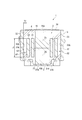
- FIG. 2 is a longitudinal sectional view of the transformer, taken along the line II-II in FIG.
- FIG. 3 is a longitudinal sectional view of the transformer, taken along the line III-III in FIG.
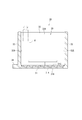
- FIG. 7 is a longitudinal sectional view of a case for explaining a machining process, and is a sectional view taken along line VII-VII in FIG. 6.
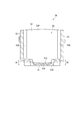
- FIG. 8 is a longitudinal sectional view of a case for explaining a machining process, and is a sectional view taken along line VIII-VIII in FIG. 6.
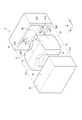
- FIG. 1 shows the transformer 1 of this embodiment in a partially disassembled state.
- 2 and 3 are a sectional view taken along line II-II and a sectional view taken along line III-III in FIG. 1, respectively.
- the transformer 1 includes a transformer main body 2 as a subassembly in which a boosting operation is performed, and a case 3 in which the transformer main body 2 is accommodated.
- the mold resin 4 is filled in the gap between the transformer main body 2 and the case 3 or the gap of the transformer main body 2.
- the mold resin 4 a silicone resin is used in the present embodiment, but an epoxy resin or an unsaturated polyester resin may be used as long as it is a thermosetting fluid resin.
- the transformer body 2 includes a core 20 having a closed magnetic circuit structure, an input-side primary coil 21 disposed in the center of the core 20, and an output-side secondary coil 22 disposed outside the primary coil 21. .
- the core 20 has a structure in which E-type cores 20A and 20B are joined vertically in the figure.
- a cylindrical magnetic core portion 25 is provided at the center of the E-type cores 20A and 20B, and primary and secondary coils 21 and 22 are wound around the magnetic core portion 25.
- the E-type cores 20A and 20B are provided with outer portions 26 and 26 on both ends in the diameter direction with the magnetic core portion 25 as the center.
- the outer portions 26 and 26 and the magnetic core portion 25 are planar portions 27. It is connected with. Such a planar portion 27 has a constricted portion where the central magnetic core portion 25 is provided in plan view.
- the case 3 is a casting made of metal (in this embodiment, aluminum) and has a substantially rectangular parallelepiped bottomed box shape having an opening 30 in the upper part. Therefore, the case 3 has a bottom surface portion 31 as a mounting surface portion that is vertically opposed to the opening 30 on the lower side, and from the outer periphery of the bottom surface portion 31, the side wall portion 32 along the short side and the long side. A side wall 33 is erected along the side. A constricted portion corresponding to the core 20 is formed on the center side of the bottom surface portion 31 (see also FIG. 6).
- the inner surface of the bottom surface portion 31 is a flat core ground surface 31A finished to a predetermined surface roughness smaller than the surface roughness of the casting surface, the core 20 is placed on the core ground surface 31A, and the lower E The lower surface 27A of the planar portion 27 forming the mold core 20B and the core ground surface 31A are in close contact with each other.
- the case 3 (transformer 1) is fixed on, for example, the heat sink 7 as a heat radiating means by a bolt inserted into a mounting portion 34 provided on the lower side.
- the outer surface of the bottom surface portion 31 of the case 3 is also finished to a predetermined surface roughness and is a contact surface 31B that is in close contact with the upper surface of the heat sink 7.
- the heat sink 7 a water-cooled type having a cooling water circuit inside is suitably used.
- it may be an air-cooled heat sink provided with heat radiation fins and cooled by cooling air.
- the structure described below is adopted to promote heat dissipation from the transformer main body 2 through the side mold resin 4 and the side walls 32 and 33 of the case 3. That is, in the cross-sectional view in the direction shown in FIG. 2, with respect to the inner wall surface 32A of the side wall portion 32 forming the case 3, the mold resin in which the outer surface 20C of the core 20 as the facing surface is filled in the gap A1.
- the four mold layers 41 are in close proximity to each other.
- the outer peripheral surface 22A of the secondary coil 22 as the opposing surface is filled in the gap A2 with respect to the inner wall surface 33A of the side wall 33 forming the case 3.
- the mold resin 4 is in close proximity to each other through the mold layer 42.
- the inner wall surface 33A and the outer peripheral surface have a predetermined length L2 (in the present embodiment, the axial length of the secondary coil 22) from the opening 30 side to the bottom surface portion 31 in the case 3. 22A is parallel, and the thickness T2 of the mold layer 42 in the gap A2 is constant.
- This structure is realized by the fact that there is no draft in the vertical direction on the surface for forming the inner wall surfaces 32A and 33A in the core used in the casting process of the case 3.
- the conventional core has a draft angle so that the area of the surface for forming the core ground contact surface of the case is smaller than the area of the surface for forming the opening. For this reason, the draft angle is transferred to the inner wall surface of the case so as to expand from the core ground surface toward the opening, and the thickness of the side wall becomes thinner as it goes to the opening. It was getting thicker as we headed to.
- the case 3 is cast using the core 5 as shown in FIG.
- the thickness L1 is constant between the lengths L1
- the thickness T2 of the mold layer 42 is constant between the predetermined lengths L2.
- FIG. 4 is a perspective view showing the core 5 and the core manufacturing mold 6 used for manufacturing the core 5.
- the core 5 is illustrated with a core ground surface forming portion 51 for forming the core ground surface 31 ⁇ / b> A of the case 3 facing upward.
- the side surfaces of the core 5 are an inner wall surface forming portion 52 for forming the inner wall surface 32A on the short side of the case 3 and an inner wall surface forming portion 53 for forming the inner wall surface 33A on the long side.
- the surface illustrated as the lower surface in FIG. 4 of the core 5 is an opening forming portion 54 for forming the opening 30 of the case 3.
- the core 5 is formed on the left and right objects with a vertical plane (YZ plane in FIG. 4) dividing the core ground plane forming part 51 and the inner wall surface forming part 52 in the left and right directions in the figure.
- a boundary appears as a dividing line 55 at a position corresponding to the dividing surface 61 ⁇ / b> A of the pair of molds 61 and 61 constituting the core manufacturing die 6.
- These molds 61 are also symmetric, and one mold 61 is removed on the positive side in the X direction in the figure, and the other mold 61 is removed on the negative side in the X direction, whereby the core 5 is formed. Is done.
- the cavity 62 in the mold 61 is divided into a first cavity surface 62A for forming the core ground surface forming portion 51 of the core 5.
- a draft angle ⁇ ⁇ b> 1 that widens toward the surface 61 ⁇ / b> A is provided. From this, it can be said that the dividing surface 61 ⁇ / b> A is set in a direction orthogonal to the first cavity surface 62 ⁇ / b> A corresponding to the bottom surface portion 31 of the case 3.
- the second cavity surface 62B for forming the opening forming portion 54 is also provided with a draft angle ⁇ 1 that is expanded toward the dividing surface 61A (only the draft angle ⁇ 1 of the first cavity surface 62A is changed). (Illustrated).
- Each of the third and fourth cavity surfaces 62C and 62D for forming the pair of inner wall surface forming portions 52 of the core 5 is provided with a draft angle ⁇ 2 that expands toward the dividing surface 61A side. (Only the draft angle ⁇ 2 of the third cavity surface 62C is shown).
- the drafts ⁇ 1 and ⁇ 2 are transferred as they are to the core 5 as the draft ⁇ 1 of the core ground surface forming portion 51 and the draft ⁇ 2 of the inner wall surface forming portion 53.
- the relationship between the other mold 61 and the core 5 is the same.
- any of the core ground surface forming portion 51, the inner wall surface forming portions 52 and 53, and the opening forming portion 54 has a Y direction (long There is no draft angle inclined with respect to the side direction) and the Z direction (vertical direction).
- the side wall portions 32 and 33 are provided. Is formed uniformly over the lengths L1 and L2. As described above, the side wall portions 32 and 33 do not taper toward the opening 30, and the thickness T1 of the mold layer 41 existing between the side wall portions 32 and 33 and the transformer body 2 is constant within the range of the length L1. Thus, the thickness T2 of the mold layer 42 is constant in the length L2 range.
- the manufacturing method of case 3 generally includes a core manufacturing process, a casting process, and a machining process, and the case 3 is manufactured in this order.
- the core manufacturing process as described with reference to FIG. 4, the core 5 is manufactured using the core manufacturing mold 6. That is, sand filling into the cavities 62 of the respective molds 61 is performed, and after the molds 61 are aligned with each other, only the mold 61 is divided again, and the sand mass is taken out to obtain the core 5.
- FIGS. 6 to 8 show the case 3A before finishing.
- the core 5 having the core contact surface forming portion 51 with the draft ⁇ 1 is used at the time of casting. It has become.
- the inclined casting surface 31C is inappropriate as a core grounding surface for grounding the core 20 of the transformer body 2, and therefore needs to be finished.
- the finishing process is the next machining step.
- the cross-hatched portion in the drawing including the casting surface 31C of the bottom surface portion 31 is removed by milling using a cutting tool M such as an end mill (see FIGS. 6 and 7).
- a cutting tool M such as an end mill (see FIGS. 6 and 7).
- the core ground surface 31A finished to a predetermined surface roughness is obtained.
- the contact surface 31B of the bottom surface portion 31 and the upper surface of the mounting portion 34 are also finished to the required surface roughness by machining.
- the other parts remain as cast surfaces.
- the case 3 is manufactured through the above steps.
- the transformer body 2 is assembled in the sub-assembly process, and the transformer body 2 is inserted into the case 3 manufactured as described above from the opening 30 and positioned. Contain. After that, all the gaps including the gaps A1 and A2 between the transformer main body 2 and the case 3 are filled with 4 mold resins from the openings 30, and the whole is heated at a predetermined temperature to cure the mold resin. What is necessary is just to hold
- the present invention is not limited to the above-described embodiments, and modifications, improvements, and the like within the scope that can achieve the object of the present invention are included in the present invention.
- the mounting surface portion of the case according to the present invention is the bottom surface portion 31 of the case 3 and is provided on the bottom side of the case 3, and the opening 30 corresponding to the opening is provided on the upper side of the case 3.
- the attachment surface portion and the opening may be located at any location according to the posture at the time of arrangement of the case, and are not limited to the above embodiment.
- the thickness of the side walls 32 and 33 of the case 3 is made uniform by casting using the core 5, and thus the thickness of the mold layers 41 and 42 is constant within a predetermined length range.
- the transformer body facing the side wall is also inclined to the gap between them.
- the thickness of the existing mold layer may be constant within a predetermined length range.
- the core ground surface 31A of the case 3 has been machined to a predetermined surface roughness.
- the metal is interposed through the metal.
- the machining may be omitted.
- transformer 1 of the above embodiment has been described for boosting, the present invention may be applied to a step-down transformer.
- the present invention can be used for a transformer in which a primary coil and a secondary coil are concentrically arranged, and also for a transformer having a structure in which primary and secondary coils are arranged in parallel.
Landscapes
- Engineering & Computer Science (AREA)
- Power Engineering (AREA)
- Manufacturing & Machinery (AREA)
- Insulating Of Coils (AREA)
- Coils Or Transformers For Communication (AREA)
- Moulds For Moulding Plastics Or The Like (AREA)
Description
従って、本発明での「所定の長さ」とは、ケースの側壁部に伝達される熱による熱分布が、開口から取付面部までの間で略均一化されるのに十分な長さをいい、ケースの開口から取付面部までの実際の長さと厳密に同じである必要はなく、より短い場合も含まれる。
すなわち、本発明での「所定の表面粗さ」とは、部材間相互の密着が確実に行われ、これにより良好な熱伝達を実現できる程度の表面粗さをいう。
図1には、本実施形態のトランス1が一部分解された状態で示されている。図2、図3はそれぞれ、図1のII-II線断面図、III-III線断面図である。図1~図3において、トランス1は、昇圧動作が行われるサブアセンブリとしてのトランス本体2と、トランス本体2が収容されるケース3とを備える。ケース3内にトランス本体2が収容された状態では、トランス本体2およびケース3の間の隙間や、トランス本体2が有する隙間にモールド樹脂4が充填される。モールド樹脂4としては、本実施形態では、シリコーン樹脂が用いられるが、エポキシ樹脂や不飽和ポリエステル系樹脂などでもよく、熱硬化性の流動性樹脂であればよい。
すなわち、図2に示す方向での断面視において、ケース3を形成する側壁部32の内壁面32Aに対しては、対向面としてのコア20の外側面20Cが、隙間A1に充填されたモールド樹脂4のモールド層41を介して近接対向している。この際、ケース3での開口30側から底面部31に向かうまでの間の所定の長さL1(本実施形態では、開口30近傍から底面部31近傍までの長さ)では、内壁面32Aと外側面20Cとが平行であり、隙間A1でのモールド層41の厚みT1が一定である。
図4において、中子5は、ケース3のコア接地面31Aを形成するためのコア接地面形成部51が上方を向いて図示されている。中子5の側面は、ケース3の短辺側の内壁面32Aを形成するための内壁面形成部52、および長辺側の内壁面33Aを形成するための内壁面形成部53になっている。中子5の図4中の下面として図示される面は、ケース3の開口30を形成するための開口形成部54である。
ケース3の製造方法としては、図5に示すように大略、中子作製工程、鋳造工程、および機械加工工程を備え、この順序でケース3が製造される。
中子作製工程では、図4に基づいて説明したように、中子作製用型6を用いて中子5を作製する。つまり、各型枠61のキャビティ62内への砂詰めを行い、型枠61を互いに合わせた後に、型枠61のみを再度分割し、砂塊を取り出して中子5を得る。
ここで、図6~図8に仕上げ前のケース3Aを示す。ケース3Aでは、鋳造時に抜き勾配θ1のコア接地面形成部51を有した中子5を使用する関係で、ケース3Aの底面部31の上面は、抜き勾配θ1が転写された鋳肌面31Cとなっている。傾斜した鋳肌面31Cは、トランス本体2のコア20を接地するコア接地面としては不適切であるため、仕上げを行う必要がある。その仕上げを行うのが、次の機械加工工程である。
以上の各工程を経てケース3が製造される。
例えば、前記実施形態では、本発明に係るケースの取付面部がケース3の底面部31であって、ケース3の底側に設けられ、開口に相当する開口30がケース3の上側に設けられていたが、取付面部や開口は、ケースの配置時の姿勢に応じていずれの箇所に位置してもよく、前記実施形態に限定されない。
Claims (6)
- 入力側の1次コイルと、出力側の2次コイルと、前記1次、2次コイルが巻回されるコアと、これらで構成されるトランス本体が収容される鋳造製のケースとを備えるとともに、前記ケースおよび前記トランス本体の間にモールド樹脂が充填されるトランスにおいて、
前記ケースは、前記トランス本体が取り付けられる取付面部と、前記取付面部を囲う側壁部と、前記取付面部と対向した位置に設けられ、かつ前記トランス本体の収容および前記モールド樹脂の充填が行われる開口とを備え、
前記側壁部の内壁面およびこれに近接対向する前記トランス本体の対向面の間の隙間に形成されたモールド層の厚みは、前記ケースの前記開口側から前記取付面部に向かう所定の長さの範囲で一定である
ことを特徴とするトランス。 - 請求項1に記載のトランスにおいて、
前記取付面部の内面は、鋳肌面の切削加工により所定の表面粗さに形成されて前記コアが接地されるコア接地面になっている
ことを特徴とするトランス。 - 請求項2に記載のトランスにおいて、
前記取付面部の外面は、鋳肌面の切削加工により所定の表面粗さに形成されて放熱手段と密接される接触面になっている
ことを特徴とするトランス。 - 請求項1ないし請求項3のいずれかに記載のトランスにおいて、
前記ケースは、
当該ケースの前記取付面部に対応したキャビティ面と直交する方向に分割面が設定された中子作製用型にて中子を作製する中子作製工程と、
前記中子作製工程で作製された中子を用いてケースを鋳込む鋳造工程とを備える製造方法にて製造されている
ことを特徴とするトランス。 - 入力側の1次コイルと、出力側の2次コイルと、前記1次、2次コイルが巻回されるコアと、これらで構成されるトランス本体が収容される鋳造製のケースとを備えるとともに、前記ケースおよび前記トランス本体の間にモールド樹脂が充填され、前記ケースは、前記トランス本体が取り付けられる取付面部と、前記取付面部を囲う側壁部と、前記取付面部と対向した位置に設けられ、かつ前記トランス本体の収容および前記モールド樹脂の充填が行われる開口とを備え、前記側壁部の内壁面およびこれに近接対向する前記トランス本体の対向面の間の隙間に形成されたモールド層の厚みは、前記ケースの前記開口側から前記取付面部に向かう所定の長さの範囲で一定であるトランスのケースの製造方法において、
前記ケースの前記取付面部に対応したキャビティ面と直交する方向に分割面が設定された中子作製用型にて中子を作製する中子作製工程と、
前記中子作製工程で作製された中子を用いてケースを鋳込む鋳造工程とを備える
ことを特徴とするトランスのケースの製造方法。 - 請求項5に記載のケースの製造方法において、
前記鋳造工程後のケースの前記取付面部に形成された前記中子の抜き勾配による傾斜した鋳肌面を除去して所定の表面粗さに仕上げる機械加工工程とをさらに備える
ことを特徴とするトランスのケースの製造方法。
Priority Applications (4)
| Application Number | Priority Date | Filing Date | Title |
|---|---|---|---|
| CN201280034312.3A CN103797551B (zh) | 2012-09-11 | 2012-10-18 | 变压器及其壳体的制造方法 |
| KR1020147032709A KR101666495B1 (ko) | 2012-09-11 | 2012-10-18 | 트랜스 및 그 케이스의 제조 방법 |
| DE201211002635 DE112012002635A5 (de) | 2012-09-11 | 2012-10-18 | Transformator und Verfahren zum Herstellen eines Gehäuses für den Transformator |
| US14/131,993 US9129735B2 (en) | 2012-09-11 | 2012-10-18 | Transformer and method for manufacturing case of the transformer |
Applications Claiming Priority (2)
| Application Number | Priority Date | Filing Date | Title |
|---|---|---|---|
| JP2012199573A JP5323975B1 (ja) | 2012-09-11 | 2012-09-11 | トランスおよびそのケースの製造方法 |
| JP2012-199573 | 2012-09-11 |
Publications (1)
| Publication Number | Publication Date |
|---|---|
| WO2014041707A1 true WO2014041707A1 (ja) | 2014-03-20 |
Family
ID=49595881
Family Applications (1)
| Application Number | Title | Priority Date | Filing Date |
|---|---|---|---|
| PCT/JP2012/076973 Ceased WO2014041707A1 (ja) | 2012-09-11 | 2012-10-18 | トランスおよびそのケースの製造方法 |
Country Status (6)
| Country | Link |
|---|---|
| US (1) | US9129735B2 (ja) |
| JP (1) | JP5323975B1 (ja) |
| KR (1) | KR101666495B1 (ja) |
| CN (1) | CN103797551B (ja) |
| DE (1) | DE112012002635A5 (ja) |
| WO (1) | WO2014041707A1 (ja) |
Families Citing this family (9)
| Publication number | Priority date | Publication date | Assignee | Title |
|---|---|---|---|---|
| JP2017017234A (ja) * | 2015-07-03 | 2017-01-19 | 日産自動車株式会社 | 変圧器および変圧器の製造方法 |
| JP6436016B2 (ja) * | 2015-08-20 | 2018-12-12 | 株式会社オートネットワーク技術研究所 | 複合材料成形体、及びリアクトル |
| US20190103212A1 (en) * | 2016-05-30 | 2019-04-04 | Mitsubishi Electric Corporation | Circuit Apparatus and Power Conversion System |
| MX2020003205A (es) | 2017-09-20 | 2020-10-22 | Siemens Ag | Tanque polimerico para alojar componentes de energia. |
| CN111768947B (zh) | 2019-04-01 | 2023-03-24 | 台达电子企业管理(上海)有限公司 | 变压器及其制造方法 |
| CN111768960B (zh) | 2019-04-01 | 2022-02-18 | 台达电子企业管理(上海)有限公司 | 灌封盒以及变压器 |
| CN111768959B (zh) * | 2019-04-01 | 2022-03-08 | 台达电子企业管理(上海)有限公司 | 变压器 |
| CN110676017A (zh) * | 2019-09-24 | 2020-01-10 | 中广核中科海维科技发展有限公司 | 一种高频高压大功率变压器 |
| CN111613415A (zh) * | 2020-04-24 | 2020-09-01 | 佛山市威龙氏电器有限公司 | 一种方便绕线的变压器铁芯以及线框 |
Citations (2)
| Publication number | Priority date | Publication date | Assignee | Title |
|---|---|---|---|---|
| JPH0969452A (ja) * | 1995-08-31 | 1997-03-11 | Toshiba Lighting & Technol Corp | 高電圧用トランス、高電圧パルス発生装置、放電灯点灯装置、照明装置及び液晶プロジェクタ |
| JP2010034228A (ja) * | 2008-07-28 | 2010-02-12 | Sumitomo Electric Ind Ltd | リアクトル |
Family Cites Families (5)
| Publication number | Priority date | Publication date | Assignee | Title |
|---|---|---|---|---|
| KR100500012B1 (ko) * | 2003-03-18 | 2005-07-07 | 동미전기공업(주) | 옥외용 주상 몰드 변압기 |
| JP2008153293A (ja) | 2006-12-14 | 2008-07-03 | Komatsu Ltd | トランス |
| JP5465151B2 (ja) * | 2010-04-23 | 2014-04-09 | 住友電装株式会社 | リアクトル |
| JP5179561B2 (ja) * | 2010-12-02 | 2013-04-10 | 三菱電機株式会社 | リアクトル装置 |
| TWI433177B (zh) * | 2010-12-22 | 2014-04-01 | Delta Electronics Inc | 變壓器結構 |
-
2012
- 2012-09-11 JP JP2012199573A patent/JP5323975B1/ja not_active Expired - Fee Related
- 2012-10-18 CN CN201280034312.3A patent/CN103797551B/zh not_active Expired - Fee Related
- 2012-10-18 WO PCT/JP2012/076973 patent/WO2014041707A1/ja not_active Ceased
- 2012-10-18 US US14/131,993 patent/US9129735B2/en not_active Expired - Fee Related
- 2012-10-18 KR KR1020147032709A patent/KR101666495B1/ko not_active Expired - Fee Related
- 2012-10-18 DE DE201211002635 patent/DE112012002635A5/de not_active Ceased
Patent Citations (2)
| Publication number | Priority date | Publication date | Assignee | Title |
|---|---|---|---|---|
| JPH0969452A (ja) * | 1995-08-31 | 1997-03-11 | Toshiba Lighting & Technol Corp | 高電圧用トランス、高電圧パルス発生装置、放電灯点灯装置、照明装置及び液晶プロジェクタ |
| JP2010034228A (ja) * | 2008-07-28 | 2010-02-12 | Sumitomo Electric Ind Ltd | リアクトル |
Also Published As
| Publication number | Publication date |
|---|---|
| JP2014056873A (ja) | 2014-03-27 |
| US9129735B2 (en) | 2015-09-08 |
| KR101666495B1 (ko) | 2016-10-14 |
| KR20150016249A (ko) | 2015-02-11 |
| US20140327507A1 (en) | 2014-11-06 |
| DE112012002635A5 (de) | 2014-04-17 |
| JP5323975B1 (ja) | 2013-10-23 |
| CN103797551B (zh) | 2016-08-17 |
| CN103797551A (zh) | 2014-05-14 |
Similar Documents
| Publication | Publication Date | Title |
|---|---|---|
| JP5323975B1 (ja) | トランスおよびそのケースの製造方法 | |
| JP2011181856A (ja) | 誘導機器の組立体 | |
| JP5964619B2 (ja) | リアクトル、及びリアクトルの製造方法 | |
| JP4635982B2 (ja) | リアクトル | |
| JP2023040439A (ja) | 電力変換装置 | |
| US9777972B2 (en) | Heat sink for a linear motor | |
| CN103650077A (zh) | 电抗器及其制造方法 | |
| US20230317338A1 (en) | Winding support for a magnetic component of an electrical assembly | |
| JP7133295B2 (ja) | リアクトル | |
| WO2014196400A1 (ja) | リアクトル、リアクトル用のコア片、コンバータ、および電力変換装置 | |
| JP5964572B2 (ja) | コイル装置用インサート成形コアの製造方法、コイル装置用リングコアユニットの製造方法、コイル装置の製造方法、及びコイル装置 | |
| KR20170022670A (ko) | 트랜스포머 | |
| JP7104538B2 (ja) | リアクトルの製造方法及びリアクトル | |
| JP6973970B2 (ja) | コアユニット及びリアクトル | |
| JP5682406B2 (ja) | リアクトル及びその製造方法 | |
| JP6851257B2 (ja) | リアクトル | |
| JP2016139634A (ja) | インダクタ部品 | |
| WO2016208441A1 (ja) | リアクトル、及びリアクトルの製造方法 | |
| JP6895967B2 (ja) | 受動的熱管理機能を含むインダクタンス回路 | |
| CN116457908B (zh) | 一种注塑成型的电感装置、压粉磁芯及注塑成型方法 | |
| CN209947601U (zh) | 变压器和变压器组件 | |
| JP2010118466A (ja) | インダクタ | |
| CN119446751B (zh) | 一种电感器制造工艺 | |
| JP6443635B2 (ja) | トランス及びトランスの製造方法 | |
| JP7751985B2 (ja) | コイル装置 |
Legal Events
| Date | Code | Title | Description |
|---|---|---|---|
| WWE | Wipo information: entry into national phase |
Ref document number: 112012002635 Country of ref document: DE Ref document number: 1120120026357 Country of ref document: DE |
|
| WWE | Wipo information: entry into national phase |
Ref document number: 14131993 Country of ref document: US |
|
| REG | Reference to national code |
Ref country code: DE Ref legal event code: R225 Ref document number: 112012002635 Country of ref document: DE Effective date: 20140417 |
|
| 121 | Ep: the epo has been informed by wipo that ep was designated in this application |
Ref document number: 12884486 Country of ref document: EP Kind code of ref document: A1 |
|
| ENP | Entry into the national phase |
Ref document number: 20147032709 Country of ref document: KR Kind code of ref document: A |
|
| 122 | Ep: pct application non-entry in european phase |
Ref document number: 12884486 Country of ref document: EP Kind code of ref document: A1 |