WO2014038651A1 - Dispositif phare de véhicule - Google Patents
Dispositif phare de véhicule Download PDFInfo
- Publication number
- WO2014038651A1 WO2014038651A1 PCT/JP2013/074022 JP2013074022W WO2014038651A1 WO 2014038651 A1 WO2014038651 A1 WO 2014038651A1 JP 2013074022 W JP2013074022 W JP 2013074022W WO 2014038651 A1 WO2014038651 A1 WO 2014038651A1
- Authority
- WO
- WIPO (PCT)
- Prior art keywords
- irradiation range
- vehicle
- coordinates
- preceding vehicle
- headlamp
- Prior art date
Links
Images


Classifications
-
- B—PERFORMING OPERATIONS; TRANSPORTING
- B60—VEHICLES IN GENERAL
- B60Q—ARRANGEMENT OF SIGNALLING OR LIGHTING DEVICES, THE MOUNTING OR SUPPORTING THEREOF OR CIRCUITS THEREFOR, FOR VEHICLES IN GENERAL
- B60Q1/00—Arrangement of optical signalling or lighting devices, the mounting or supporting thereof or circuits therefor
- B60Q1/02—Arrangement of optical signalling or lighting devices, the mounting or supporting thereof or circuits therefor the devices being primarily intended to illuminate the way ahead or to illuminate other areas of way or environments
- B60Q1/04—Arrangement of optical signalling or lighting devices, the mounting or supporting thereof or circuits therefor the devices being primarily intended to illuminate the way ahead or to illuminate other areas of way or environments the devices being headlights
- B60Q1/06—Arrangement of optical signalling or lighting devices, the mounting or supporting thereof or circuits therefor the devices being primarily intended to illuminate the way ahead or to illuminate other areas of way or environments the devices being headlights adjustable, e.g. remotely-controlled from inside vehicle
- B60Q1/08—Arrangement of optical signalling or lighting devices, the mounting or supporting thereof or circuits therefor the devices being primarily intended to illuminate the way ahead or to illuminate other areas of way or environments the devices being headlights adjustable, e.g. remotely-controlled from inside vehicle automatically
- B60Q1/085—Arrangement of optical signalling or lighting devices, the mounting or supporting thereof or circuits therefor the devices being primarily intended to illuminate the way ahead or to illuminate other areas of way or environments the devices being headlights adjustable, e.g. remotely-controlled from inside vehicle automatically due to special conditions, e.g. adverse weather, type of road, badly illuminated road signs or potential dangers
-
- B—PERFORMING OPERATIONS; TRANSPORTING
- B60—VEHICLES IN GENERAL
- B60Q—ARRANGEMENT OF SIGNALLING OR LIGHTING DEVICES, THE MOUNTING OR SUPPORTING THEREOF OR CIRCUITS THEREFOR, FOR VEHICLES IN GENERAL
- B60Q1/00—Arrangement of optical signalling or lighting devices, the mounting or supporting thereof or circuits therefor
- B60Q1/02—Arrangement of optical signalling or lighting devices, the mounting or supporting thereof or circuits therefor the devices being primarily intended to illuminate the way ahead or to illuminate other areas of way or environments
- B60Q1/04—Arrangement of optical signalling or lighting devices, the mounting or supporting thereof or circuits therefor the devices being primarily intended to illuminate the way ahead or to illuminate other areas of way or environments the devices being headlights
- B60Q1/14—Arrangement of optical signalling or lighting devices, the mounting or supporting thereof or circuits therefor the devices being primarily intended to illuminate the way ahead or to illuminate other areas of way or environments the devices being headlights having dimming means
- B60Q1/1415—Dimming circuits
- B60Q1/1423—Automatic dimming circuits, i.e. switching between high beam and low beam due to change of ambient light or light level in road traffic
- B60Q1/143—Automatic dimming circuits, i.e. switching between high beam and low beam due to change of ambient light or light level in road traffic combined with another condition, e.g. using vehicle recognition from camera images or activation of wipers
-
- B—PERFORMING OPERATIONS; TRANSPORTING
- B60—VEHICLES IN GENERAL
- B60Q—ARRANGEMENT OF SIGNALLING OR LIGHTING DEVICES, THE MOUNTING OR SUPPORTING THEREOF OR CIRCUITS THEREFOR, FOR VEHICLES IN GENERAL
- B60Q2300/00—Indexing codes for automatically adjustable headlamps or automatically dimmable headlamps
- B60Q2300/05—Special features for controlling or switching of the light beam
- B60Q2300/056—Special anti-blinding beams, e.g. a standard beam is chopped or moved in order not to blind
-
- B—PERFORMING OPERATIONS; TRANSPORTING
- B60—VEHICLES IN GENERAL
- B60Q—ARRANGEMENT OF SIGNALLING OR LIGHTING DEVICES, THE MOUNTING OR SUPPORTING THEREOF OR CIRCUITS THEREFOR, FOR VEHICLES IN GENERAL
- B60Q2300/00—Indexing codes for automatically adjustable headlamps or automatically dimmable headlamps
- B60Q2300/10—Indexing codes relating to particular vehicle conditions
- B60Q2300/14—Other vehicle conditions
-
- B—PERFORMING OPERATIONS; TRANSPORTING
- B60—VEHICLES IN GENERAL
- B60Q—ARRANGEMENT OF SIGNALLING OR LIGHTING DEVICES, THE MOUNTING OR SUPPORTING THEREOF OR CIRCUITS THEREFOR, FOR VEHICLES IN GENERAL
- B60Q2300/00—Indexing codes for automatically adjustable headlamps or automatically dimmable headlamps
- B60Q2300/40—Indexing codes relating to other road users or special conditions
- B60Q2300/41—Indexing codes relating to other road users or special conditions preceding vehicle
Definitions
- the present invention relates to a vehicle headlamp device.
- an AFS Adaptive Front-Lighting System, variable light distribution headlamp
- AFS Adaptive Front-Lighting System, variable light distribution headlamp
- a high-beam variable headlamp system that detects the position of the vehicle in front and follows the light-shielding part to ensure a wide field of view and make it easy to find pedestrians without giving glare to the driver of the vehicle ahead. (Adaptive Driving Beam System) is known.
- Patent Document 1 coordinate information of a preceding vehicle is calculated based on information captured by a camera, a headlamp is swiveled (swiveled: turned, turned) by an actuator, and an irradiation range is moved to the left and right.
- a headlamp device that causes a light shielding portion to follow a preceding vehicle is disclosed.
- Patent Document 1 when a headlight device as disclosed in Patent Document 1 is actually mounted on a vehicle and a running evaluation is performed, it has been found that there may be annoyance. For example, because the preceding vehicle moves regardless of the intention of the driver of the following vehicle, it is troublesome that the irradiation range of the headlamp of the own vehicle closely follows the movement of the preceding vehicle when the steering is frequently operated. felt.
- the headlamp is misdetected as the front vehicle and the headlamp is swiveled so that the irradiation range is withdrawn from the reflector in the direction away from the front vehicle. Since the reflector does not shine, the headlamp is also swiveled to approach the vehicle ahead. Then, since the reflecting plate shines again, a hunting phenomenon of repeatedly swiveling the headlamp so as to retract the irradiation range away from the reflecting plate in a direction away from the preceding vehicle occurs, and it feels troublesome.
- the intermediate high beam not only illuminates far away, but also illuminates the near part. Therefore, it is easy to understand that the irradiation range that illuminates the roadside trees and sound barriers moves well.
- the present invention has been made in view of the above-described problems, and is a vehicle headlamp device that does not cause glare to the driver or passenger of the preceding vehicle and does not cause the driver of the host vehicle to feel annoyance.
- the purpose is to provide.
- the invention according to claim 1, which has been made to achieve the above object, includes a headlamp for irradiating the front of the vehicle, an irradiation range changing means for changing the irradiation range of the headlamp, and a front of the vehicle.
- a vehicle headlamp device comprising: detection means for detecting the position of an existing forward vehicle; and control means for controlling the irradiation range changing means based on the position of the forward vehicle detected by the detection means. And determining means for determining whether or not the position of the preceding vehicle is within the irradiation range, and the control means determines that the position of the preceding vehicle is within the irradiation range by the determining means.
- the irradiation range changing means is controlled to change the irradiation range such that the position of the front vehicle is outside the irradiation range, and when it is determined that the position of the front vehicle is outside the irradiation range, Irradiation range Wherein the relative does not perform additional or said irradiation range changing means performs control to suppress a change in the irradiation range.
- the control unit controls the irradiation range changing unit so that the position of the front vehicle is out of the irradiation range. Since the irradiation range is changed as described above, the driver and passengers of the vehicle ahead do not feel glare. In addition, when it is determined that the position of the vehicle ahead is outside the irradiation range, the irradiation range is not changed or the irradiation range changing unit is controlled to suppress the change of the irradiation range. The driver does not feel bothered by frequent movement of the irradiation range.
- the detection means includes a camera that images the front of the vehicle, and image processing means that generates image information including coordinates of the front vehicle from an image captured by the camera.
- the position of the vehicle ahead is specified by the end coordinates indicating the left and right positions of the end in the vehicle width direction
- the determination means performs the determination based on a comparison between reference coordinates indicating the inner limit position of the irradiation range and the end coordinates,
- the control means controls the irradiation range changing means so that the reference coordinates coincide with the end coordinates.
- the irradiation range is changed.
- the detection unit generates image information including the coordinates of the preceding vehicle from the captured image in front of the vehicle, and uses the end coordinates indicating the left and right positions of the vehicle width direction end of the preceding vehicle to detect the preceding vehicle. Since the position is specified, there is an effect that the vehicle ahead can be detected accurately and in a short time. Further, the determination means makes a determination based on a comparison between the reference coordinates indicating the inner limit position of the irradiation range and the end coordinates, and the control means determines that the position of the front vehicle is within the irradiation range by the determination means. In this case, since the irradiation range is changed so that the reference range coincides with the end coordinates by controlling the irradiation range changing means, the position of the irradiation range can be made accurate.
- the determination means calculates a shift amount between a reference coordinate indicating the inner limit position of the irradiation range and the end coordinates, and performs the determination based on the shift amount. It is characterized by that.
- the irradiation range changing means can be controlled by the control means separately when the amount of deviation is large and small, so that the change of the irradiation range can be made more appropriate in each case. it can.
- ECU electronic controller
- the vehicle headlamp device 1 includes an in-vehicle camera 2, a rudder angle sensor 3, a wheel speed sensor 4, an ECU (ECU: Electronic Control Unit) 5, and a headlamp. 6 and 7.
- the in-vehicle camera 2 is provided inside the front window of the vehicle, images the front of the vehicle, and sends data to the ECU 5.
- the rudder angle sensor 3 is an existing sensor provided for ESC (Electronic Stability Control, skid prevention device), and is provided in the steering mechanism.
- the steering angle sensor 3 detects the steering angle of the vehicle and sends a steering angle signal indicating the detection result to the ECU 5.
- the wheel speed sensor 4 is an existing sensor provided for ABS (Anti-lock Braking System). The wheel speed sensor 4 detects the rotational speed of the vehicle wheel and sends a wheel speed signal indicating the detection result to the ECU 5.
- the ECU 5 is a control device for controlling the headlamps 6 and 7.
- the ECU 5 includes an image processing unit 51, a determination unit 52, and a control unit 53.
- the image processing unit 51 performs image processing on the data of the in-vehicle camera 2 and calculates the position of the preceding vehicle (preceding vehicle or oncoming vehicle) as coordinates.
- the determination unit 52 determines the direction and amount of deviation between the position of the preceding vehicle and the irradiation range of the headlamp.
- the control unit 53 instructs the headlamps 6 and 7 to switch the light distribution pattern and to perform a swivel operation.
- the control unit 53 also instructs the headlamps 6 and 7 to perform a swivel operation as a conventional AFS based on the steering angle signal output from the steering angle sensor 3 and the wheel speed signal output from the wheel speed sensor 4. be able to.
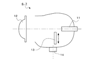
- each headlamp 6, 7 has a light source 11, a lens 12, a shade mechanism 13, and an actuator 14.
- the light source 11 is a halogen lamp.
- the shade mechanism 13 has a plurality of shade plates (not shown), and is inserted into a part of an optical path formed inside the headlamp and shielded by an instruction from the control unit 53 of the ECU 5, thereby shielding the intermediate high beam pattern. Or a low beam pattern.
- the shade mechanism 13 forms a high beam pattern by completely retracting from the optical path.
- the headlamps 6 and 7 each have these three light distribution patterns.
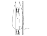
- the intermediate high beam is a concave light distribution pattern in which the front vehicle portion is shielded from light so as not to give glare to the occupant of the front vehicle.
- What is formed by the left headlamp is an irradiation range 21 having a substantially L-shaped light distribution pattern
- what is formed by the right headlamp is a light distribution pattern obtained by horizontally inverting the substantially L-shaped light distribution pattern.
- the irradiation range is at a position where the positions of the left and right ends of the vehicle ahead coincide with the position of the cut line in the vertical direction of the irradiation range. For this reason, the position of the vehicle ahead is confirmed at any time and the headlamp is swiveled.
- the intermediate high beam has the same brightness as the high beam except for the light-shielding part, so if you inadvertently irradiate the vehicle ahead, you will feel glare directly into the eyes of the driver of the oncoming vehicle. Further, in the preceding vehicle, the light reflected from the mirrors enters the eyes of the driver of the preceding vehicle, or the interior of the preceding vehicle is brightly illuminated, making it difficult to check the outside situation. Therefore, in order to avoid such a situation, it is necessary to calculate the swivel angle when the light distribution pattern of the headlamp is switched from the high beam or the low beam to the intermediate high beam.
- the actual light distribution pattern is not symmetrical and illuminates the left side of the vehicle, but is not related to the description of the present invention.
- the headlamps 6 and 7 can be switched to a high beam mode, a low beam mode, or an ADB mode with a manual switch.
- the high beam variable headlamp system is referred to as ADB (Adaptive Driving Beam).
- the ADB mode is an automatic switching mode, and by setting the ADB mode, the control unit 53 of the ECU 5 automatically controls the left and right headlamps to be a high beam, or separately controls the left and right headlamps to an intermediate high beam and a low beam.
- ADB Adaptive Driving Beam
- the control unit 53 of the ECU 5 switches the left and right headlamps to a high beam when there is no vehicle ahead. Also, when there is a vehicle ahead, the left and right headlamps are used as intermediate high beams.
- control unit 53 of the ECU 5 turns the left headlamp to a low beam when the preceding vehicle makes a left turn or the like and the swivel angle of the left headlamp becomes equal to or larger than a predetermined angle. At this time, the right headlamp remains an intermediate high beam.
- Control is performed such that only the right headlamp is made into a low beam.
- a light distribution pattern as shown in FIGS. 3 and 4 can be realized by covering a predetermined portion below the optical path.
- Actuator 14 causes the entire headlamp to swivel around the rotation axis in accordance with an instruction from control unit 53 of ECU 5.
- the conventional AFS is operated in conjunction with the steering angle of the steering.
- the swivel operation is performed so as to move the irradiation range according to the position of the preceding vehicle based on the data from the in-vehicle camera 2.
- the flowchart of FIG. 5 represents the processing of the ECU 5 when the headlamp is set to the ADB mode and the intermediate high beam is obtained.
- initial processing such as data initialization and mode determination is omitted.
- the start in FIG. 5 is a state in which these initial processes are completed.
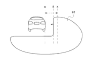
- the reference coordinates are obtained based on instruction information from the control unit 53 of the ECU 5 to the actuator 14 of the headlamp. 6 to 8, the right end coordinate of the preceding vehicle is indicated as D, and the reference coordinate of the irradiation range 22 is indicated as E.
- step-1 when a preceding vehicle is detected (step-1; hereinafter abbreviated as S-1; the same applies to other steps), the right end coordinate of the preceding vehicle is calculated (S-2).
- Information from the in-vehicle camera 2 is image-processed by the image processing unit 51 of the ECU 5 and, for example, a pair of red tail lamps is detected to obtain the right end coordinates.
- Misalignment (Right end coordinate-Reference coordinate) (1) Is calculated (S-3).
- the right side is the positive direction and the left side is the negative direction. Therefore, when the irradiation range 22 illuminates the preceding vehicle as shown in FIG. 6, the deviation amount calculated by the equation (1) is positive (S-4: YES).
- A is set as a filter constant (S-5).
- the filter constant A is, for example, 1.0.
- the target coordinates to which the reference coordinates should be moved are calculated according to the following equation (2).
- Target coordinate filter constant x right end coordinate + (1-filter constant) x standard coordinate (2)
- Equation (3) the target coordinates obtained by Equation (3) are for setting the amount of deviation obtained in S-3 to zero. Subsequently, a counter for another process to be described later is reset (S-9), the process returns to the start, and the flow from the vehicle detection (S-1) is executed again.
- the set value X is, for example, ⁇ 1 °.
- B is set as a filter constant (S-11).
- the filter constant B is, for example, 0.5.
- Target coordinate 0.5 x right end coordinate + 0.5 x standard coordinate (4) It becomes. That is, the target coordinate is a coordinate that internally divides the right end coordinate and the reference coordinate by 1: 1, in other words, an average value of the right end coordinate and the reference coordinate.
- the headlamp is operated so that the amount of deviation between the right end coordinates of the preceding vehicle and the reference coordinates of the irradiation range 22 is halved ( S-7).
- the reference coordinates are moved to the target coordinates (S-8). Note that the target coordinates obtained by Equation (4) halve the amount of deviation obtained in S-3.
- a counter for another process to be described later is reset (S-9), the process returns to the start, and the flow from the vehicle detection (S-1) is executed again.
- C is set as a filter constant (S-21).
- the filter constant C is, for example, 0.1.
- the reference coordinates are moved to the target coordinates (S-8).
- the target coordinates obtained by the equation (5) are for setting the amount of deviation obtained in S-3 to 90%.
- the counter for S-20 is reset (S-9), the process returns to the start, and the flow from the vehicle detection (S-1) is executed again.
- the light from the reflecting plate may be erroneously recognized as the tail lamp of the preceding vehicle as a result of image processing of information from the in-vehicle camera 2.
- S-4 is YES
- the target coordinates are moved to the end of the reflector.
- the tail lamp of the correct preceding vehicle is recognized, but since S-10 is NO, the reference coordinates are maintained. Accordingly, it is possible to prevent the occurrence of a hunting phenomenon in which light repeatedly reaches or does not reach the reflector and the reference coordinates of the irradiation range reciprocate between the reflector and the vehicle end.
- the right end position of the preceding vehicle is far from the irradiation range 22 and is smaller than a predetermined set value as an absolute value. If it is at an angle, if the condition for 5 [s] continues, the reference coordinates are maintained and the headlamp is not moved. Thereafter, the irradiation range 22 is brought closer to the preceding vehicle by 10% of the deviation amount. In addition, when the right end position of the preceding vehicle is far from the irradiation range 22, if the angle is larger than a predetermined set value as an absolute value, the headlamp is swiveled so that the target coordinate approaches the preceding vehicle by 50% of the deviation amount.
- the irradiation range 22 as shown in FIGS. 7 and 8 is away from the preceding vehicle, there is no concern that the light of the headlamp makes the driver of the preceding vehicle feel glare. It is not necessary to match the reference coordinates of the irradiation range 22 with the right end coordinates of the preceding vehicle. Therefore, the irradiation range is moved over time or 50%.
- the headlamps (headlamps 6 and 7) that illuminate the front of the vehicle and the illumination ranges (21 and 22) of the headlamps are changed.
- detection means vehicle camera 2, image processing unit 51
- a determination means for determining whether or not the preceding vehicle position is within the irradiation range.
- the control means controls the irradiation range changing means to change the irradiation range so that the preceding vehicle position is outside the irradiation range.
- the preceding vehicle position is If it is determined that the ⁇ performs control to suppress a change in the irradiation range with respect to not change or irradiation range changing means irradiation range.
- the detection unit is an in-vehicle camera 2 that captures the front of the vehicle, and an image processing unit that generates image information including the coordinates of the preceding vehicle from the captured image of the camera 2 (image processing unit 51).
- the preceding vehicle position is specified by end coordinates indicating the left and right positions of the vehicle width direction end portion of the preceding vehicle
- the determination means includes reference coordinates indicating the inner limit position of the irradiation range and A determination is made based on the comparison with the end coordinates.
- the control means controls the irradiation range changing means to perform a reference. The irradiation range is changed so that the coordinates coincide with the end coordinates.
- the determination unit calculates a shift amount between the reference coordinates indicating the inner limit position of the irradiation ranges 21 and 22 and the end coordinates, and sets the shift amount. Judgment is made based on this.
- control unit 53 when the amount of deviation calculated by the determination unit (determination unit 52) is greater than or equal to a predetermined value, sets the end coordinates and the reference coordinates to a predetermined ratio ( The target coordinates to be internally divided by the first predetermined ratio) are calculated, the irradiation range changing means (actuator 14) is controlled, the irradiation ranges 21 and 22 are changed so that the reference coordinates coincide with the target coordinates, and the determination means (determination)
- the amount of deviation calculated by the unit 52) is less than a predetermined value
- the irradiation ranges 21 and 22 are not changed until the state continues for a predetermined time, and after the predetermined time elapses, the end coordinates and the reference Target coordinates for dividing the coordinates at another predetermined ratio (second predetermined ratio) different from the first predetermined ratio are calculated, and the irradiation range changing means (actuator 14) is controlled to match the reference coordinates with the target coordinates.
- second predetermined ratio predetermined ratio
- control means calculates the target coordinates that internally divide the right end coordinates and the reference coordinates, for example, 1: 1, and changes the irradiation range changing means (actuator 14). And the irradiation ranges 21 and 22 may be changed so that the reference coordinates coincide with the target coordinates.
- the irradiation range is changed to halve the amount of deviation without immediately matching the irradiation range to the vehicle end. If this process is repeated, the position is detected again without any significant movement, and the target coordinates to be changed based on the new deviation amount are calculated. Even if it fluctuates, the movement of the irradiation range can be reduced as a result, and it can be prevented from feeling bothersome.
- control means does not change the irradiation ranges 21 and 22 until it continues for a predetermined time, and the end coordinates and the reference coordinates are obtained after the predetermined time has elapsed.
- target coordinates that are internally divided into 9: 1 may be calculated, and the irradiation ranges 21 and 22 may be changed so that the reference coordinates coincide with the target coordinates by controlling the irradiation range changing means (actuator 14).
- the irradiation range is frequently changed because the irradiation range is not changed until the state continues for a predetermined time. There is no, and I do not feel bothersome.
- the irradiation range is changed so that the amount of deviation is 90%. If this process is repeated, it appears that the irradiation range slowly approaches the preceding vehicle. It can be minimized to feel bothered by frequent movement of the irradiation range.
- the preceding vehicle has been described.
- the in-vehicle camera 2 detects the light of the headlamp of the oncoming vehicle, the left and right ends can be detected similarly for the oncoming vehicle. Control can be applied.
- the in-vehicle camera 2 may be used as a camera provided for other purposes, for example, a camera provided for a collision avoidance device.
- the filter constant B is set to 0.5 and the filter constant C is set to 0.1.
- other values may be used.
- the target coordinates are calculated according to the target coordinate calculation formula (2).
- the light source of the headlamp is a halogen lamp, but it may be an LED lamp, an HID lamp (HID is a registered trademark), or other light sources.
- the reference coordinates are obtained based on the instruction information from the ECU 5 to the actuator 14 of the headlamps 6 and 7, but the instruction information to the actuator 14 is used as an auxiliary, and the information of the in-vehicle camera 2 is imaged. It may be obtained by processing.
- the embodiment has been described on the assumption that the vehicle is on the left side, such as Japan and the UK, but the same applies to the case where the vehicle is on the right side.
Abstract
Priority Applications (3)
| Application Number | Priority Date | Filing Date | Title |
|---|---|---|---|
| CN201380046357.7A CN104640742B (zh) | 2012-09-07 | 2013-09-06 | 车辆用前照灯装置 |
| DE112013004381.5T DE112013004381T8 (de) | 2012-09-07 | 2013-09-06 | Fahrzeugscheinwerfervorrichtung |
| US14/426,330 US9487123B2 (en) | 2012-09-07 | 2013-09-06 | Vehicular headlamp apparatus |
Applications Claiming Priority (2)
| Application Number | Priority Date | Filing Date | Title |
|---|---|---|---|
| JP2012-197123 | 2012-09-07 | ||
| JP2012197123A JP5941800B2 (ja) | 2012-09-07 | 2012-09-07 | 車両用前照灯装置 |
Publications (1)
| Publication Number | Publication Date |
|---|---|
| WO2014038651A1 true WO2014038651A1 (fr) | 2014-03-13 |
Family
ID=50237257
Family Applications (1)
| Application Number | Title | Priority Date | Filing Date |
|---|---|---|---|
| PCT/JP2013/074022 WO2014038651A1 (fr) | 2012-09-07 | 2013-09-06 | Dispositif phare de véhicule |
Country Status (5)
| Country | Link |
|---|---|
| US (1) | US9487123B2 (fr) |
| JP (1) | JP5941800B2 (fr) |
| CN (1) | CN104640742B (fr) |
| DE (1) | DE112013004381T8 (fr) |
| WO (1) | WO2014038651A1 (fr) |
Families Citing this family (13)
| Publication number | Priority date | Publication date | Assignee | Title |
|---|---|---|---|---|
| WO2012137332A1 (fr) | 2011-04-07 | 2012-10-11 | パイオニア株式会社 | Système de détection des conditions autour d'un corps mobile |
| DE102015012023A1 (de) * | 2015-09-21 | 2017-03-23 | Audi Ag | Verfahren zum Betreiben einer Beleuchtungseinrichtung eines Kraftfahrzeugs und zugerhöriges Kraftfahrzeug |
| AT517811B1 (de) * | 2015-10-07 | 2017-11-15 | Zkw Group Gmbh | Verfahren zur Steuerung einer adaptiven Lichtfunktion sowie Kraftfahrzeugscheinwerfer |
| JP6567960B2 (ja) * | 2015-11-17 | 2019-08-28 | 株式会社小糸製作所 | 車両用灯具システム |
| CN106891801A (zh) * | 2015-12-21 | 2017-06-27 | 北京奇虎科技有限公司 | 近远光自动切换方法、装置和汽车 |
| JP6305456B2 (ja) * | 2016-03-31 | 2018-04-04 | 株式会社Subaru | 表示装置 |
| JPWO2019082980A1 (ja) * | 2017-10-26 | 2020-11-12 | 株式会社小糸製作所 | 車両用前照灯システム、車両用ランプシステム |
| WO2019159765A1 (fr) * | 2018-02-15 | 2019-08-22 | 株式会社小糸製作所 | Dispositif de détection de véhicule et système de phare de véhicule |
| TWI668140B (zh) * | 2018-04-17 | 2019-08-11 | 財團法人車輛研究測試中心 | 車輛頭燈自適應避光方法 |
| US10369923B1 (en) | 2018-04-30 | 2019-08-06 | Automotive Research & Testing Center | Operation method of adaptive driving beam headlamp system |
| US11034286B2 (en) | 2018-09-10 | 2021-06-15 | Lumileds Holding B.V. | Adaptive headlamp system for vehicles |
| CN110509836B (zh) * | 2019-06-20 | 2023-01-20 | 马瑞利汽车零部件(芜湖)有限公司 | 一种adb前照灯系统的车辆合并与处理方法 |
| CN113815522A (zh) * | 2020-06-16 | 2021-12-21 | 奥迪股份公司 | 调节车辆的照明装置的方法和设备及相关车辆和存储介质 |
Citations (2)
| Publication number | Priority date | Publication date | Assignee | Title |
|---|---|---|---|---|
| JP2011001043A (ja) * | 2009-06-22 | 2011-01-06 | Koito Mfg Co Ltd | 車両用前照灯の配光制御システム |
| JP2012162105A (ja) * | 2011-02-03 | 2012-08-30 | Koito Mfg Co Ltd | 車両用前照灯装置 |
Family Cites Families (9)
| Publication number | Priority date | Publication date | Assignee | Title |
|---|---|---|---|---|
| US6396397B1 (en) * | 1993-02-26 | 2002-05-28 | Donnelly Corporation | Vehicle imaging system with stereo imaging |
| US6587573B1 (en) * | 2000-03-20 | 2003-07-01 | Gentex Corporation | System for controlling exterior vehicle lights |
| JP4130345B2 (ja) * | 2002-09-20 | 2008-08-06 | 株式会社小糸製作所 | 車両用前照灯装置 |
| JP4087201B2 (ja) * | 2002-09-20 | 2008-05-21 | 株式会社小糸製作所 | 車両用前照灯装置の光軸位置設定方法 |
| JP4437712B2 (ja) | 2004-07-07 | 2010-03-24 | 株式会社小糸製作所 | 車両用照明システム |
| JP5363085B2 (ja) * | 2008-12-03 | 2013-12-11 | 株式会社小糸製作所 | 前照灯制御装置 |
| JP2012020715A (ja) * | 2010-07-16 | 2012-02-02 | Toyota Motor Corp | 照射装置、照射方法、プログラム及び媒体 |
| JP5243505B2 (ja) * | 2010-09-13 | 2013-07-24 | 株式会社日本自動車部品総合研究所 | 車両用前照灯 |
| JP5833861B2 (ja) * | 2011-08-11 | 2015-12-16 | 株式会社小糸製作所 | 車両用前照灯装置および配光制御方法 |
-
2012
- 2012-09-07 JP JP2012197123A patent/JP5941800B2/ja active Active
-
2013
- 2013-09-06 CN CN201380046357.7A patent/CN104640742B/zh active Active
- 2013-09-06 US US14/426,330 patent/US9487123B2/en active Active
- 2013-09-06 WO PCT/JP2013/074022 patent/WO2014038651A1/fr active Application Filing
- 2013-09-06 DE DE112013004381.5T patent/DE112013004381T8/de active Active
Patent Citations (2)
| Publication number | Priority date | Publication date | Assignee | Title |
|---|---|---|---|---|
| JP2011001043A (ja) * | 2009-06-22 | 2011-01-06 | Koito Mfg Co Ltd | 車両用前照灯の配光制御システム |
| JP2012162105A (ja) * | 2011-02-03 | 2012-08-30 | Koito Mfg Co Ltd | 車両用前照灯装置 |
Also Published As
| Publication number | Publication date |
|---|---|
| JP5941800B2 (ja) | 2016-06-29 |
| JP2014051190A (ja) | 2014-03-20 |
| CN104640742A (zh) | 2015-05-20 |
| US9487123B2 (en) | 2016-11-08 |
| US20150239392A1 (en) | 2015-08-27 |
| CN104640742B (zh) | 2016-11-23 |
| DE112013004381T5 (de) | 2015-05-21 |
| DE112013004381T8 (de) | 2015-07-23 |
Similar Documents
| Publication | Publication Date | Title |
|---|---|---|
| WO2014038651A1 (fr) | Dispositif phare de véhicule | |
| JP5947682B2 (ja) | 車両用前照灯装置 | |
| EP2266838B1 (fr) | Dispositif de phare de véhicule | |
| JP5719620B2 (ja) | 車両用前照灯の配光制御装置 | |
| JP6048199B2 (ja) | 車両用照明装置 | |
| JP5333539B2 (ja) | 前照灯配光制御装置 | |
| US9187027B2 (en) | Vehicle headlight | |
| EP2731825B1 (fr) | Dispositif de commande de distribution de lumière de véhicule et procédé de commande de distribution de lumière de véhicule | |
| JP5976345B2 (ja) | 車両用前照灯の点灯制御装置及び車両用前照灯システム | |
| US8866387B2 (en) | Vehicular headlight apparatus | |
| JP5814982B2 (ja) | すれ違い用配光向け車両用前照灯 | |
| JP2011037342A (ja) | 車両用前照灯システム | |
| JP2012183874A (ja) | 車両用前照灯の配光制御装置 | |
| JP6054042B2 (ja) | 車両用前照灯の点灯制御装置及び車両用前照灯システム | |
| EP2388163A2 (fr) | Système de phare de véhicule, dispositif de contrôle, et phare de véhicule | |
| JP2017177941A (ja) | 車両の配光制御装置 | |
| JP2013163417A (ja) | 車両用前照灯の点灯制御装置、車両用前照灯システム | |
| JP7103865B2 (ja) | 車両用前照灯装置及び車両用前照灯の制御方法 | |
| JP2012001079A (ja) | 車両用灯具システム、制御装置および車両用灯具 | |
| JP2024024496A (ja) | ヘッドランプ制御装置および車両 | |
| JP5937896B2 (ja) | 車両用前照灯の制御システム | |
| JP2012081865A (ja) | 前照灯制御装置 |
Legal Events
| Date | Code | Title | Description |
|---|---|---|---|
| 121 | Ep: the epo has been informed by wipo that ep was designated in this application |
Ref document number: 13834580 Country of ref document: EP Kind code of ref document: A1 |
|
| WWE | Wipo information: entry into national phase |
Ref document number: 14426330 Country of ref document: US |
|
| WWE | Wipo information: entry into national phase |
Ref document number: 112013004381 Country of ref document: DE Ref document number: 1120130043815 Country of ref document: DE |
|
| 122 | Ep: pct application non-entry in european phase |
Ref document number: 13834580 Country of ref document: EP Kind code of ref document: A1 |