WO2014038525A1 - 機能水発生器 - Google Patents
機能水発生器Info
- Publication number
- WO2014038525A1 WO2014038525A1 PCT/JP2013/073605 JP2013073605W WO2014038525A1 WO 2014038525 A1 WO2014038525 A1 WO 2014038525A1 JP 2013073605 W JP2013073605 W JP 2013073605W WO 2014038525 A1 WO2014038525 A1 WO 2014038525A1
- Authority
- WO
- WIPO (PCT)
- Prior art keywords
- functional water
- water
- electrolysis
- electrode
- functional
- Prior art date
- Legal status (The legal status is an assumption and is not a legal conclusion. Google has not performed a legal analysis and makes no representation as to the accuracy of the status listed.)
- Ceased
Links
Images




Classifications
-
- F—MECHANICAL ENGINEERING; LIGHTING; HEATING; WEAPONS; BLASTING
- F24—HEATING; RANGES; VENTILATING
- F24F—AIR-CONDITIONING; AIR-HUMIDIFICATION; VENTILATION; USE OF AIR CURRENTS FOR SCREENING
- F24F6/00—Air-humidification, e.g. cooling by humidification
-
- C—CHEMISTRY; METALLURGY
- C02—TREATMENT OF WATER, WASTE WATER, SEWAGE, OR SLUDGE
- C02F—TREATMENT OF WATER, WASTE WATER, SEWAGE, OR SLUDGE
- C02F1/00—Treatment of water, waste water, or sewage
- C02F1/46—Treatment of water, waste water, or sewage by electrochemical methods
- C02F1/4602—Treatment of water, waste water, or sewage by electrochemical methods for prevention or elimination of deposits
-
- A—HUMAN NECESSITIES
- A61—MEDICAL OR VETERINARY SCIENCE; HYGIENE
- A61L—METHODS OR APPARATUS FOR STERILISING MATERIALS OR OBJECTS IN GENERAL; DISINFECTION, STERILISATION OR DEODORISATION OF AIR; CHEMICAL ASPECTS OF BANDAGES, DRESSINGS, ABSORBENT PADS OR SURGICAL ARTICLES; MATERIALS FOR BANDAGES, DRESSINGS, ABSORBENT PADS OR SURGICAL ARTICLES
- A61L2209/00—Aspects relating to disinfection, sterilisation or deodorisation of air
- A61L2209/20—Method-related aspects
- A61L2209/21—Use of chemical compounds for treating air or the like
- A61L2209/213—Use of electrochemically treated water, e.g. electrolysed water or water treated by electrical discharge
-
- C—CHEMISTRY; METALLURGY
- C02—TREATMENT OF WATER, WASTE WATER, SEWAGE, OR SLUDGE
- C02F—TREATMENT OF WATER, WASTE WATER, SEWAGE, OR SLUDGE
- C02F1/00—Treatment of water, waste water, or sewage
- C02F1/46—Treatment of water, waste water, or sewage by electrochemical methods
- C02F1/461—Treatment of water, waste water, or sewage by electrochemical methods by electrolysis
- C02F1/46104—Devices therefor; Their operating or servicing
- C02F1/46109—Electrodes
- C02F2001/46119—Cleaning the electrodes
Definitions
- This invention relates to the functional water generator which can produce
- electrolysis is performed using a platinum electrode on the anode side and a carbon electrode on the cathode side, and oxygen is used on the anode side. Generate (release the liberated hydrogen ions in water) to lower (acidify) the pH of the solution.
- Patent Document 2 since the electrode for electrolysis is arranged in a state where the electrode surface is in the vertical direction at the lower part of the water supply tank, the height of the electrode is determined when the whole electrode is cleaned. It was necessary to leave functional water as much as that, and the amount of available functional water was reduced accordingly.
- an object of the present invention is to provide a highly convenient functional water generator that can make maximum use of the functional water generated in the electrolytic vessel.
- the functional water generator according to the present invention is provided with an electrolysis unit including an anode and a cathode in an electrolysis vessel, and water supplied into the electrolysis vessel is supplied to the electrolysis unit.
- an electrolysis unit including an anode and a cathode in an electrolysis vessel
- water supplied into the electrolysis vessel is supplied to the electrolysis unit.
- a functional water generator that performs electrode washing to elute the hardness component adhering to the electrode during functional water generation into the water by flowing a current in the opposite direction to that during functional water generation to the electrode of the electrolysis unit,
- the anode and the cathode are arranged to face each other in parallel in the vertical direction.
- the anode and cathode (hereinafter sometimes simply referred to as “electrode”) of the electrolysis section are laid sideways so that the electrode surface faces in the horizontal direction, and the anode and cathode are spaced apart in the vertical direction. Since the electrodes are arranged opposite to each other, the thickness direction of the electrodes is a vertical direction, and the volume of the electrolysis portion in the electrolytic vessel is smaller than that in the state where the electrodes are erected. Accordingly, it is possible to reduce the amount of remaining functional water during electrode cleaning.
- functional water means acidic water obtained by electrolysis.
- both anode and cathode electrodes are immersed means that both electrodes are immersed in functional water so that current can be passed between the anode and cathode.
- the electrode of the electrolysis part may be composed of a material that does not dissolve by electrolysis.
- a metal electrode that easily undergoes electrolysis on its surface can be used as an anode when generating functional water, and an electrode that can adsorb ions can be used as a cathode.
- an electrode having platinum on the surface can be used.
- a platinum electrode or a metal electrode coated with platinum for example, titanium can be used.
- a carbon electrode made of a conductive carbon material for example, carbon fiber, activated carbon, etc.
- activated carbon having a large specific surface area that adsorbs ions is at least part of the carbon electrode. It is preferable to use for.
- the activated carbon electrode it is possible to effectively adsorb hardness components such as Mg ions and Ca ions dissolved in water such as tap water using the porous adsorption surface of the activated carbon electrode. Even if the adsorption surface of the activated carbon electrode is clogged with hardness components and cannot be regenerated due to the use over time, it can be easily returned to the initial state by replacing the activated carbon electrode because it is relatively inexpensive compared to platinum.
- the anode (metal electrode) at the time of generating functional water may be arranged above the cathode (carbon electrode).
- the cathode carbon electrode
- the anode which generates oxygen gas is arranged above the cathode, oxygen gas does not accumulate on the cathode, and electrolysis can be performed efficiently.
- acid-alkali ions at the time of electrolysis: H + ions, at the time of electrode cleaning: OH ⁇ ions
- concentration of the functional water in an electrolytic vessel can be fixed.
- the electrolysis of water is mainly performed at the anode, the hydrogen ions generated during the generation of functional water diffuse up and down the anode, resulting in a large loss in electrolysis efficiency.
- the hardness component is adsorbed to the cathode when the functional water is generated, but when the water between the anode and the cathode is small, the hardness component is adsorbed from the entire water contained in the electrolytic vessel when electrolyzing the functional water. It becomes difficult.
- the anode can move in the vertical direction following the water surface in the electrolytic vessel.
- the anode should be moved to follow the fluctuation of the water surface so that the entire electrode is always immersed in water so that it is located near the lower surface of the water surface (1 mm to 10 mm below the water surface). That's fine.
- the position of the anode can be moved up and down following the water surface, and when electrolyzing functional water, the hardness component is removed from the entire water contained in the electrolytic vessel. Since it becomes possible to adsorb
- water electrolysis is mainly performed at the anode, hydrogen ions generated during the generation of functional water can only diffuse downward from the anode, so that the hydrogen ions generated at the anode are involved in the conduction between the anode and cathode, and voltage Can be reduced (electric conductivity can be increased), so that the efficiency of electrolysis can be improved.
- a float may be attached to the anode of the electrolysis unit so that the anode moves in the vertical direction following the water surface in the electrolytic vessel.
- the anode By attaching a float to the anode, the anode can always be maintained at a certain distance away from the water surface without using a special drive mechanism. Thereby, when electrolyzing water, it becomes possible to adsorb
- a device such as a stirrer that stirs the water in the electrolytic vessel or the electrode of the electrolysis unit is vibrated.
- a bubble removing device that removes bubbles adhering to the electrolysis part, such as a swinging device or an ultrasonic vibrator.
- the cathode (carbon electrode) at the time of generating functional water may be disposed above the anode (metal electrode).
- the carbon electrode can be directly washed away with washing water, and the alkaline water component and hardness component remaining on the cathode surface can be more effectively removed.
- the drain port may function as a water supply port for supplying water into the electrolytic container in a state where the electrolytic container is detached from the main body.
- the drain port is turned upward during water supply and functions as a water supply port, the anode and the cathode of the electrolysis unit are in an upright state, and the stability of water is not easily spilled due to shaking of the hand. Some water supply is possible.
- the drain port is turned downward and functions as a waste water port. At this time, the anode and cathode of the electrolysis part are in an upright state, and the residual water flows along the surface of the electrode toward the drain port, so that the hardness component and the like still attached to the electrode surface are effectively removed. It becomes possible.
- the functional water discharged from the discharge unit can be used as it is, but may be configured to include a diffusion unit that discharges the functional water into the air in the form of mist or steam. . By diffusing the functional water into the air, it is possible to humidify and to prevent the hardness component from adhering to the furniture and the window glass.
- a mist generating device that mists functional water as a diffusion part
- by spraying functional water that is acidic water into the space or the human body without changing the pH of the functional water When sprayed into the space, it can be suitably used for air cleaning or humidification applications such as prevention of bacterial infection due to the bactericidal effect of functional water.
- sprayed on the skin it can be suitably used for cosmetic purposes such as a disinfection effect due to the astrogen effect, activation of the skin, etc., and skin tightening effect.
- the anode and the cathode of the electrolysis part are arranged to face each other in parallel in the vertical direction, it is possible to make maximum use of the functional water generated in the electrolytic vessel.
- FIG. 4 is a schematic diagram for explaining a reaction during electrode cleaning in the functional water generator of FIG. 3. It is a schematic structure perspective view of an electrolysis part. It is a figure which shows the state which introduce
- the functional water generator of FIG. 8 it is a schematic diagram which shows the state which introduce
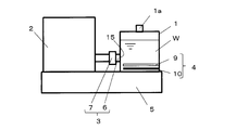
- FIG. 1 is a diagram illustrating a configuration of a functional water generator according to the present invention, and is a schematic diagram illustrating a state in which water is supplied into an electrolytic vessel.
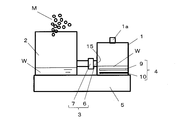
- FIG. 2 is a diagram illustrating functional water generated in the functional water generator of FIG. It is a schematic diagram which shows the state which drained from the electrolytic vessel and was introduce
- the functional water generator of the present invention is a single tank system, an electrolytic vessel 1 that electrolyzes water W to generate functional water, a diffusion portion 2 that diffuses functional water into the air, and a drain port 15 of the electrolytic vessel 1
- a discharge unit 3 that connects the diffusion unit 2 to introduce functional water from the electrolytic vessel 1 to the diffusion unit 2
- an electrolysis unit 4 installed in the electrolytic vessel 1 and the diffusion unit 2 are detachable.
- a main body portion 5 attached to the main body 5.
- the discharge part 3 is composed of a pipe 6 connecting the drain port 15 and the diffusion part 2 and an on-off valve 7 interposed in the middle of the pipe 5 so that the water W in the electrolytic vessel 1 can be drained.
- An electrolysis unit 4 is provided in the lower part of the electrolytic vessel 1.
- the electrolysis part 4 is comprised from the platinum electrode 9 as an anode at the time of functional water production
- the electrolysis part 4 unites the platinum electrode 9 and the carbon electrode 10 and is provided so that attachment or detachment with respect to the electrolytic vessel 1 is preferable, it is preferable at the point that a maintenance and electrode replacement are easy.
- the functional water generator of the present invention enables the electrolytic vessel 1 to be attached to and detached from the main body portion 5 without moving the main body portion 5 with water remaining in the container after electrode cleaning. It becomes possible to drain easily. As a result, user maintenance can be simplified. In addition, since it is possible to prevent the main body 5 and the like from being splashed with water during cleaning, malfunction due to a short circuit can be prevented. In addition, in order to take an electrical contact at the time of attachment / detachment, a contact is provided on both the electrolytic vessel 1 side and the main body 5 side so as to make an electrical contact.
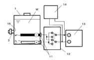
- the main body 5 is provided with a contact electrode 11 for energizing the platinum electrode 9 and the carbon electrode 10 of the electrolytic vessel 1 mounted on the main body 5.
- a constant current generating source 13 is connected to the contact electrode 11 via a switching circuit 12.
- the direction of the current supplied to the contact electrode 11 is switched and controlled by the control device 14.
- the control device 14 is composed of a microcomputer, and controls the amount of current supplied to the electrolysis unit 4 and the direction of the current, as well as the opening / closing of the on-off valve 7 and the operation of the diffusion unit 2.
- the platinum electrode 9 and the carbon electrode 10 are both formed in a flat plate shape, and the platinum electrode 9 and the carbon electrode 10 are arranged opposite to each other in parallel in the vertical direction. In the present embodiment, the platinum electrode 9 is disposed above the carbon electrode 10.
- the drain port 15 is provided at a position higher than the electrolysis unit 4, that is, a position higher than the upper surface of the platinum electrode 9. Thereby, even if the on-off valve 7 is opened and the water W in the electrolytic vessel 1 is drained from the drain port 15, the platinum electrode 9 and the carbon electrode 10 as a whole are immersed in the water W as shown in FIG. Kept.
- the platinum electrode 9 and the carbon electrode 10 are laid sideways so that the electrode surface faces the horizontal direction X, and both the electrodes 9 and 10 are arranged to face each other with an interval in the vertical direction Y.
- the volume of the electrolysis part 4 occupying in the electrolytic vessel is small.
- the amount of drainage can be increased when the platinum electrode 9 and the carbon electrode 10 are all drained while leaving the amount of water sufficient to maintain the state immersed in the water W.
- the electrode surface in the horizontal direction X means that the volume of the electrolysis part may be reduced by lying down compared to the state in which the electrode surface is oriented in the vertical direction. There is no problem even if it is inclined.
- FIG. 7 is a diagram for explaining the outline of the operation content of the functional water generator.
- water W is supplied into the one tank type electrolytic vessel 1 from the water supply port 1a.
- normal tap water can be used.
- current value 500 mA
- electrode size 150 mm ⁇ 100 mm
- Electrolysis can be performed at a relatively low voltage value of 30 V or less, with a current applied at a distance of 15 mm.
- electrolytic additives such as KCl and NaCl are added at about 0.1 to 1 wt% to promote electrolysis (lower the voltage value). Also good.
- Electrolysis is performed in a state in which the inside of the electrolytic vessel 1 is full and the electrodes 9 and 10 of the electrolysis unit 4 are immersed in water. As shown in FIG. 3, the electrolysis is performed using the platinum electrode 9 as an anode and the carbon electrode 10 as a cathode. Functional water generated by electrolysis is acidified. Specifically, when the water to be electrolyzed is 500 ml, the electrolysis is performed at 500 mA, the electrode size: 150 mm ⁇ 100 mm, and the distance between the electrodes: 15 mm for 4 minutes, so that the pH is about 3.0 to 3.2. Functional water.
- the functional water generator of this embodiment is electrolyzed by a batch system.
- the batch system means that after adding a predetermined amount of water to the electrolytic vessel, electrolysis is performed without substantially taking in and out the water in the electrolytic vessel.
- the carbon electrode 10 serving as the cathode utilizes the porous adsorption surface of the carbon electrode as shown in the following reaction formula (2) for hardness components such as Mg ions and Ca ions dissolved in water such as tap water. It is effectively adsorbed as electric double layer ions.
- gas is accumulated by providing a slit in the platinum electrode, arranging a plurality of platinum electrodes formed in a strip shape at intervals in the horizontal direction, or forming a mesh shape. It can be made difficult, and acid-alkali ions generated on the platinum electrode can be effectively convected above and below the platinum electrode. Furthermore, if a bubble removing device that removes bubbles adhering to the electrolysis unit, such as a device for stirring water in the electrolytic vessel, a device that vibrates or swings the electrode of the electrolysis unit, or an ultrasonic vibrator, is used. By increasing the area of water in contact with the electrodes 9 and 10 and further homogenizing the water in the electrolytic vessel, electrolysis can be performed more efficiently.
- a minimum of 5 mm or more is provided between the ends of the electrodes 9 and 10 and the electrolytic vessel 1 except for the electrode base end connected to the contact electrode 11. It is desirable that the interval is wide. By doing so, coupled with the action of the bubble removing device, convection in the electrolytic vessel 1 is more likely to occur, and electrolysis can be performed more efficiently.
- the electrolysis can reduce the concentration of hardness components in the generated functional water.
- a spray-type humidifier calcium and magnesium salts adhere to furniture and window glass. Can be suppressed. Moreover, it can suppress that a hardness component accumulates as a scale on a humidification filter etc. by using functional water for a heating-type humidifier.
- the pH of the functional water is preferably 2.5 or more and 5.0 or less.
- the pH of the functional water is slightly shifted to the neutral side due to the boiling of water, but the original functional water is water whose hardness component has been reduced by electrolysis. For this reason, it is possible to prevent the hardness component (scale), which becomes a problem when tap water is used for steam, from accumulating in the vicinity of the ejection port, and to prevent the occurrence of troubles such as the ejection port being clogged and not being ejected.
- steam injection it has a humidifying effect in the air, and when it is sprayed on the skin, it has an effect of improving skin moisture by warm steam.
- water In order to generate steam, water needs to be boiled, and this may be raised and boiled in a single stage or in multiple stages by means of a heater such as a ceramic heater.
- the watering tank may be either a mist generating tank or a steam generating tank, or may be provided with both.
- the base metal is, for example, platinum, gold, palladium, rhodium, iridium, etc., functional water that is acidic water. Other than metals that are stable).
- the base metal is, for example, platinum, gold, palladium, rhodium, iridium, etc.
- functional water that is acidic water.
- the base metal is, for example, platinum, gold, palladium, rhodium, iridium, etc.
- functional water that is acidic water.
- the above-described heater be a material that hardly reacts with functional water, such as a ceramic heater.
- the control device 14 ends the electrolysis when a predetermined amount of current flows in the water in the electrolytic vessel 1 and opens the on-off valve 7 so that the generated functional water passes through the discharge unit 3 and the diffusion unit 2.
- the diffusion unit 2 is provided with a device for misting or steaming the functional water, and the operation of the device is started by the control device 14, whereby the functional water is diffused into the air in the state of mist M or steam. .
- the electrodes 9 and 10 are immersed in the functional water, and as shown in FIG. 4, the electrode cleaning is performed by causing the control device 14 to pass a current in the direction opposite to that during electrolysis.
- the carbon electrode 10 becomes an anode and the platinum electrode 9 becomes a cathode.
- the hardness component M adhering to the electrode surface is eluted as M 2+ as shown in the following reaction formula (3).
- reaction formula (4) On the other hand, on the surface of the platinum electrode serving as the cathode, a reaction represented by the following reaction formula (4) occurs, and hydrogen gas (H 2 ) and hydroxide ions (OH ⁇ ) are generated. That is, residual water can be converted to alkaline water by the above reaction, and hardness components such as Ca ions and Mg ions adsorbed on the carbon electrode can be eluted.
- the electric current value applied to the residual water does not depend on the residual amount of functional water, and it is sufficient to flow the same amount of electricity as at the time of generating the functional water. For example, 500 mA for 4 minutes or 250 mA for 8 minutes. I just need it.
- electrolysis, drainage of functional water, and electrode cleaning are automatically executed by the control device 14.
- the convenience of the user can be enhanced, and the electrodes can be automatically maintained in a good state.
- drainage of functional water and electrode cleaning may be performed manually after electrolysis.
- the anode and the cathode may be a pair or more, for example, the anode and the cathode may be alternately arranged at intervals in the vertical direction.
- the elution of the hardness component of the carbon electrode may be performed each time functional water is generated in the electrolytic vessel, or may be performed after the functional water is generated about 5 to 10 times.
- the discharge part 3 is provided so that isolation
- FIGS. 3 and 4 it is preferable to use a valve that does not discharge water when the discharge part 3 is separated, that is, when the electrolytic vessel 1 is detached from the main body part 5.
- tap water as the water used for the electrolysis of the electrolysis unit 4.
- tap water contains hardness components such as Ca ions and Mg ions in advance, and these contribute to ion conduction, so that electrolysis can be performed at a relatively low voltage. Therefore, even when a relatively low voltage value is used with normal tap water, electrolysis can be performed at a low voltage (low power), and the running cost of the user can be reduced.
- electrolytic additive such as KCl or NaCl may be added (about 0.1 to 1 wt%) for convenience.
- functional water is generated by electrolysis using a platinum electrode as an anode.
- the electrode used for the anode here may be an electrode member that does not dissolve, and may be carbon or the like.
- a metal that can be efficiently electrolyzed for example, any one of platinum, gold, palladium, rhodium, and iridium (or an alloy thereof) is suitable.
- the surface of an electrode made of titanium is coated with platinum. It may be a thing.
- the water from which the hardness component has been eluted after electrode cleaning can be discarded by the user before the next generation of functional water, and is discarded immediately before the next use and supplied with a new solution.
- FIG. 8 and 9 are diagrams showing a second embodiment of the present invention.
- FIG. 8 is a schematic diagram of a functional water generator in a state where the electrolytic vessel is full.
- FIG. 9 shows functional water generated by electrolysis. The schematic diagram of the functional water generator of the state introduced into the spreading
- the point which attached the float to the platinum electrode 9 is a point which is different from the functional water generator in FIG. 1, and is the same as that of FIG.
- the functional water generator of the present embodiment can move the position of the platinum electrode 9 in the vertical direction following the liquid level by attaching the float 8 to the end of the platinum electrode 9 as the anode in the electrolytic vessel 1. It is said. That is, as shown in FIG. 8, when electrolyzing the water stored in the electrolytic vessel 1, the platinum electrode 9 follows the water surface and rises to the top of the electrolytic vessel 1. Electrolyzed to produce functional water.
- the platinum electrode 9 descends following the surface of the functional water as shown in FIG. Then, by applying a current in the opposite direction to the generation of functional water to the water remaining in the electrolytic vessel 1, the hardness component adsorbed to the activated carbon electrode at the time of generation of the functional water can be reduced with a minimum amount of water. It can be removed by elution.
- FIG. 10 compares the generation time of functional water when the electrode interval is actually changed (electrolysis condition: 300 mL of water, electrode size: 90 mm ⁇ 70 mm, distance between electrodes: 300 mA, 500 mA at 10 mm). Apply current).
- the electrolysis time can be shortened by moving the anode to follow the water surface.
- the hardness component adsorbed to the activated carbon electrode at the time of generating the functional water can be eluted and removed with a minimum amount of water.
- the anode may be moved following the fluctuation of the water surface so as to be located 1 mm to 10 mm below the water surface.
- the float is preferably made of a smooth member so that it can move in the vertical direction while sliding on the electrolytic vessel wall surface.
- the time to be shortened becomes shorter as the applied current value becomes larger.
- the current density is desirably 120 A / m 2 or less.
- FIG. 11 is a schematic diagram for explaining a third embodiment of the present invention.
- the drain port 15 is automatically closed.
- the drain port 15 is provided so that it can be opened manually, and functions as the water supply port 1a when water is supplied.
- water W is supplied into the electrolytic vessel 1 as the water supply port 1a.
- water W ordinary tap water can be used.
- the electrolysis container 1 is put in the original state (a state where the drainage port 15 is turned sideways) and attached to the main body 5.
- contacts are provided on both the electrolytic vessel 1 side and the main body 5 side so as to make electrical contact.
- the opening / closing of the discharge unit 3 is controlled by opening / closing the opening / closing valve 7.
- electric power is supplied from the main body 5 to the electrolytic vessel 1, and electrolysis is started.
- functional water having a pH of about 2.5 to 5.0 is generated.
- the open / close valve 7 provided in the functional water generator main body is set to OPEN, so that the functional water generated in the electrolytic vessel 1 is introduced into the main body portion 5 through the discharge portion 3. (After introducing the functional water into the functional water generator body, applying a reverse current in the electrolytic vessel allows the hardness component adhering to the activated carbon electrode to be eluted and removed from the residual water).
- the drain port is turned upward during water supply and functions as a water supply port, so that the anode and cathode of the electrolysis unit are in an upright state, and the stability that water does not spill out due to hand tremors, etc. It is possible to supply water.
- the drain port is turned downward and functions as a waste water port. At this time, the anode and cathode of the electrolysis part are in an upright state, and the residual water flows along the surface of the electrode toward the drain, so that the hardness component remaining on the electrode surface can be effectively removed. Is possible.
- FIG. 12 to FIG. 15 are diagrams for explaining the fourth embodiment of the present invention.
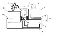
- the functional water storage part for storing the functional water W1 generated by electrolysis and the alkaline water storage part for storing the alkaline water generated by electrode cleaning are formed separately, and the pipe 6 of the discharge part 3 is provided. It is characterized in that it is connected to the bottom of the electrolytic vessel 1, and the other configuration is the same as that of the first embodiment.
- FIG. 12 is a diagram showing a configuration of the functional water generator of the present embodiment, and is a schematic diagram showing a state where water is supplied into the electrolytic vessel.
- diffusion part 2 in 1st embodiment functions as a functional water storage part which stores functional water.
- FIG. 14 is a schematic view showing a state in which the functional water remaining in the electrolytic vessel in the functional water generator of FIG. 13 is subjected to electrode cleaning, and the generated alkaline water is introduced into the alkaline water storage unit.
- the alkaline water storage unit 18 is detachably attached to the main body unit 5.
- the discharge part 3 is formed so that the functional water W1 or the alkaline water W2 is discharged from the electrolytic vessel 1 and introduced into the functional water storage part 2 or the alkaline water storage part 18.
- the discharge unit 3 includes a pipe 6 whose one end is connected to the electrolysis vessel 1 and whose other end is branched via a branch 6a, and a flow path switching member 17 interposed in the pipe 6.
- the functional water storage unit 2 and the alkaline water storage unit 18 are connected to the other end of the pipe 6.
- One end of the pipe 6 is connected to the bottom of the electrolytic vessel 1.
- the flow path switching member 17 includes an on-off valve 7a interposed in a pipe between the branch part 6a and the electrolytic vessel 1, and an on-off valve 7b interposed in a pipe between the branch part 6a and the functional water storage unit 2.
- an on-off valve 7c interposed in a pipe between the branch part 6a and the alkaline water storage part 18.
- the control device 14 controls the opening / closing of the on-off valves 7a to 7c of the flow path switching member 17 and the operation of the mist generating device.
- FIG. 15 is a diagram for explaining the outline of the operation content of the functional water generator of the present embodiment.
- the control device 14 performs electrolysis of water in the electrolytic vessel 1 in the same manner as in the first embodiment. Then, the electrolysis is terminated when a predetermined amount of current flows through the water, and the on-off valves 7a to 7c of the flow path switching member 17 are controlled to open and close, thereby generating the generated functional water W1 as shown in FIG.
- the functional water storage unit 2 is introduced through the discharge unit 3. Specifically, the on-off valves 7a and 7b are opened with the on-off valve 7c closed.
- the flow path between the electrolysis container 1 and the functional water storage part 2 is opened while the flow path between the electrolysis container 1 and the alkaline water storage part 18 is closed, and the function in the electrolysis container 1 is maintained.
- the water W1 flows into the functional water storage unit 2 until the height of the water surface is the same as the functional water W1 in the functional water storage unit 2.
- the position and the size of the functional water storage unit 2 may be adjusted so that the functional water W1 in an amount soaking the entire electrodes 9 and 10 of the electrolysis unit remains in the electrolytic vessel.
- control device 14 performs electrode cleaning by flowing a current having an amount of electricity equivalent to that at the time of acid water generation in the opposite direction to that during electrolysis.
- a pH sensor or a conductivity sensor In order to ensure the pH control of alkaline water, it is desirable to monitor the functional water storage unit with a pH sensor or a conductivity sensor.
- the pH of the alkaline water W2 is preferably from 9.0 to 11.5.
- the on-off valves 7a and 7c are opened while the on-off valve 7b is closed.
- the alkaline water is transferred from the electrolytic vessel 1 to the alkaline water storage unit 18 using gravity without using a pump or the like.
- W2 can be introduced.
- the alkaline water W2 stored in the alkaline water storage unit 18 may be used for washing the face, or may be discarded when the amount of the alkaline water storage unit 18 is large.
- alkaline water W2 is used for skin cleaning
- hydroxide ions (OH ⁇ ) in alkaline water react with oils and fats on the skin surface to cause a so-called saponification reaction as shown in the following reaction formula (5).
- saponification reaction As shown in the following reaction formula (5).
- the convenience of the functional water generator can be further enhanced by effectively using the alkaline water W2.
- Na + represents sodium ions existing on the skin.
- the entire platinum electrode 9 and the carbon electrode 10 are kept immersed in the functional water W1. It becomes possible to increase the amount of functional water discharged to the functional water storage unit 2. That is, the amount of functional water W1 that can be used can be increased.
- the amount of alkaline water W2 generated by electrode cleaning can be suppressed, and the alkaline water W2 for multiple times of electrode cleaning can be stored in the alkaline water storage unit 18. Therefore, it is possible to save the trouble of taking out the alkaline water W2 remaining in the electrolytic vessel every time the electrode is cleaned, and to obtain a highly convenient functional water generator.
- the functional water generator of the present invention is provided with an electrolysis unit comprising an anode and a cathode in an electrolysis vessel, and water supplied into the electrolysis vessel is supplied to the electrolysis unit. After the functional water is generated by electrolysis, the functional water is left in the electrolytic container so that both the anode and the cathode are immersed when the functional water is discharged from the electrolytic container.
- a functional water generator that performs electrode cleaning to elute the hardness component adhering to the electrode at the time of generating functional water into water by flowing an electric current in the direction opposite to that at the time of generating functional water to the electrode of the decomposition unit,
- a functional water storage unit that stores functional water generated by electrolysis and an alkaline water storage unit that stores alkaline water generated by electrode cleaning are formed separately from the electrolytic vessel.
- a discharge unit that discharges alkaline water may be provided in the electrolytic vessel, and the alkaline water storage unit may be connected to the discharge unit.
- a discharge part can also be formed separately from the discharge part which discharge
- the discharge part for discharging the functional water and alkaline water from the electrolytic container one end side is connected to the electrolytic container, and the other end side is branched from the branch part, and the pipe is interposed in the pipe.
- the functional water storage unit and an alkaline water storage unit for storing alkaline water generated after the electrode cleaning is connected to the other end side of the pipe. It can. Thereby, a structure can be simplified as the whole functional water generator.
- one end side of the pipe is connected to the bottom part of the electrolysis container, and after electrolyzing water supplied to the electrolysis container in a state where the discharge part is closed, by the flow path switching member, When the flow path between the electrolytic vessel and the functional water storage unit is opened while the flow channel between the electrolytic vessel and the alkaline water storage unit is closed, both electrodes of the electrolysis unit are immersed. You may set the position of the said functional water storage part so that the quantity of functional water to remain
- the functional water in an amount necessary for electrode cleaning can remain in the electrolytic vessel simply by switching the flow path with the flow path switching member.
- setting the position of the functional water storage unit specifically means that when the functional water storage unit of any size is used, the position (height) is adjusted to adjust the position of the electrolytic vessel and alkaline water.
- the height of the functional water in the electrolytic vessel is What is necessary is just to make it balance with the height of the water surface of a functional water storage part by the height which the whole electrode immerses.
- the flow path switching member keeps the flow path between the electrolysis container and the functional water storage section closed.
- the position of the alkaline water storage part may be set so that the alkaline water in the electrolytic vessel flows into the alkaline water storage part when the flow path between the alkaline water storage part and the alkaline water storage part is opened.
- the bottom of the alkaline water storage unit is adjusted to be lower than the bottom of the electrolytic vessel.
- it adjusts so that the whole alkaline water storage part may become a position lower than the electrolytic vessel bottom face.
- alkaline water can be introduce
- the electrodes of the electrolysis part may be arranged such that the anode and the cathode are opposed in parallel to each other in the vertical direction. Thereby, the thickness direction of the electrode becomes the vertical direction, and the volume of the electrolysis part occupying in the electrolytic vessel may be smaller than in the state where the electrode is erected. Accordingly, it is possible to reduce the amount of remaining functional water during electrode cleaning. As a result, the amount of alkaline water generated by one electrode cleaning can be reduced, and the effort for discarding the alkaline water accumulated in the alkaline water storage unit can be reduced.
- alkaline water is used for washing the skin, as described above, hydroxide ions (OH ⁇ ) in the alkaline water cause a saponification reaction with oil on the skin surface, and the reaction product has a surface-active effect. Demonstrates a cleaning effect.
- the convenience of the functional water generator can be further enhanced by effectively using alkaline water.
- alkaline water to the skin When applying alkaline water to the skin from the alkaline water storage unit, it may be applied directly to the skin in a liquid state, or may be sprayed locally on the skin in the form of a mist.
- functional water it is preferable to apply functional water to the skin after washing the skin with alkaline water. That is, when the skin is washed with alkaline water and the pH on the skin is inclined to be alkaline, an environment in which various germs easily propagate on the skin is obtained. Therefore, finally, by applying functional water to the skin and tilting the pH of the skin to acidity, it is possible to suppress the propagation of germs on the skin.
- the functional water obtained with the functional water generator of the present invention when applied to the skin, only the functional water is applied to the skin without washing the skin with alkaline water, or with alkaline water. When performing skin washing, it is preferable to apply functional water to the skin afterwards.
- the platinum electrode 9 is disposed above the carbon electrode 10, but not limited thereto, the carbon electrode 10 is disposed above the platinum electrode 9 as shown in FIG. 6. Is also possible. Thereby, when washing
- the carbon electrode since the water to be electrolyzed passes through the carbon electrode by placing the carbon electrode on the top, dust components such as fine particles in water can be adsorbed by the adsorption action of the carbon electrode, and the water is purified. Can also be achieved.
- the carbon electrode in order to wash off the carbon electrode with cleaning water effectively, is preferably as porous as possible, and the thickness is desirably 4 mm or less.
- the on-off valves 7a to 7c are used as the flow path switching member 17.
- the present invention is not limited to this, and for example, a three-way valve may be installed in the branch portion 6a.
- the positions of the functional water storage unit 2 and the alkaline water storage unit 18 are set with reference to the position of the electrolysis vessel 1, and the opening / closing valves 7a to 7c are controlled to open and close, thereby using gravity.
- the functional water W1 and the alkaline water W2 are introduced into the functional water storage unit 2 and the alkaline water storage unit 18, respectively.
- the present invention is not limited to this. A fixed amount of functional water W1 and alkaline water W2 may be discharged.
Landscapes
- Chemical & Material Sciences (AREA)
- Engineering & Computer Science (AREA)
- General Chemical & Material Sciences (AREA)
- Electrochemistry (AREA)
- Life Sciences & Earth Sciences (AREA)
- Hydrology & Water Resources (AREA)
- Chemical Kinetics & Catalysis (AREA)
- Environmental & Geological Engineering (AREA)
- Water Supply & Treatment (AREA)
- Organic Chemistry (AREA)
- Combustion & Propulsion (AREA)
- Mechanical Engineering (AREA)
- General Engineering & Computer Science (AREA)
- Water Treatment By Electricity Or Magnetism (AREA)
Abstract
電解容器内で生成した機能水を最大限利用可能な機能水発生器を提供することを目的とする。 電解容器1内に陽極及び陰極から成る電気分解部4が設けられ、電解容器1内に供給された水Wを電気分解部4にて電気分解することにより機能水を生成した後、電解容器1の排出部3から機能水を排出する際に、陽極及び陰極の両電極の少なくとも一部が浸漬するように、電解容器1内に機能水を残留させ、電気分解部4の電極に対して機能水生成時とは逆向きの電流を流すことにより、機能水生成時に電極に付着した硬度成分を水中に溶出させる電極洗浄を行う機能水発生器であって、陽極と陰極とが垂直方向に平行に対向配置された構成とする。
Description
本発明は、陽極及び陰極からなる電気分解部を用いて機能水を生成可能な機能水発生器に関する。
従来の電気二重層を利用したイオン濃度調整装置では、陽イオン用および陰イオン用の各イオン吸着電極間に電圧を印加して、水中のイオンを移動させることによりイオン量の制御を行い、軟水化および硬水化を行うものがある(特許文献1参照)。
しかしながら、上記イオン濃度調整装置では、吸着速度を上げるために印加電圧を高くすると、イオン吸着電極表面で電気二重層イオンが固着してしまい、イオンの吸着および脱着が行われなくなるために、硬度成分のみを増減させることができなくなるという問題がある。
また、別の従来例では、電気分解部を用いて水を電気分解し、機能水を作成する場合、陽極側に白金電極、陰極側に炭素電極を用いて電気分解を行い、陽極側で酸素発生(遊離した水素イオンを水中に溶出)させて、溶液のpHを低下(酸性化)させる。
この場合、電気分解用の水として水道水を用いると、陰極側の炭素電極でCaイオン、Mgイオンなどの硬度成分が吸着する。よって、得られた電気分解後の水(機能水)に含まれるCaイオンやMgイオン濃度を低減することができ、得られた機能水を噴霧式の加湿器に使用することで、家具や窓ガラスにカルシウム塩やマグネシウム塩が付着するのを抑制することが可能となる。また、機能水を加熱式の加湿器に使用することで、加湿フィルタ等に硬度成分がスケールとして堆積するのを抑制することが可能となる。
一方で、陰極に炭素電極を用いて何度も電気分解を行うと、炭素電極表面が硬度成分に覆われてしまい、イオン吸着電極の吸着容量が無くなるために、最終的には所望の電気分解ができなくなるため、適宜、電極の極性を反転させ、硬度成分を溶出させていた(特許文献2参照)。
ところで、特許文献2では、電気分解用の電極は、給水タンクの下部において電極表面が垂直方向になるように立てた状態で配置されているため、電極全体を洗浄しようとすると、電極の高さ分だけ機能水を残留させる必要があり、その分、利用できる機能水の量が少なくなっていた。
そこで、本発明においては、電解容器内で生成した機能水を最大限利用可能で利便性の高い機能水発生器を提供することを目的とする。
上記問題点を解決するために、本発明に係る機能水発生器は、電解容器内に陽極及び陰極から成る電気分解部が設けられ、前記電解容器内に供給された水を前記電気分解部にて電気分解することにより機能水を生成した後、電解容器の排水口から前記機能水を排出する際に、前記陽極及び陰極の両電極が浸漬するように電解容器内に機能水を残留させ、電気分解部の電極に対して機能水生成時とは逆向きの電流を流すことにより、機能水生成時に電極に付着した硬度成分を水中に溶出させる電極洗浄を行う機能水発生器であって、前記陽極と陰極とが垂直方向に平行に対向配置されたことを特徴とする。
すなわち、本発明では、電気分解部の陽極及び陰極(以下、単に「電極」ということがある)を横倒しにして電極表面が水平方向を向くようにし、陽極と陰極とを垂直方向に間隔をおいて対向配置したため、電極の厚み方向が垂直方向となり、電極を立てた状態に比べて電解容器内に占める電気分解部の容積は小さくて済む。したがって、電極洗浄の際に、残存させる機能水量を少なくすることが可能となる。
ここで、機能水とは、電気分解により得られた酸性水を意味する。また、「陽極及び陰極の両電極が浸漬する」とは、陽極及び陰極間で通電が可能なように両電極ともに少なくとも一部が機能水に浸漬されていることを意味する。ただ、電極の全体に付着した硬度成分を効率よく溶出させるには、両方の電極の全体を機能水に浸漬することが望ましい。
なお、電気分解部の電極としては、電気分解によって溶解しない素材で構成されていればよい。具体的には、機能水生成時の陽極としてその表面で電気分解が生じやすい金属電極を、陰極としてイオンを吸着可能な電極を用いることができる。金属電極としては、白金が表面に存在する電極を用いることができ、具体的には、白金電極や白金でコートされた金属電極(たとえばチタン)を挙げることができる。これにより、機能水生成時に酸素ガスを放出し、残った水素イオンが水中に遊離することで、酸性化する。
一方、陰極のイオン吸着電極としては、導電性の炭素材料(例えばカーボン繊維、活性炭等)からなる炭素電極を用いることができ、中でもイオンを吸着する比表面積の大きい活性炭を炭素電極の少なくとも一部に用いるのが好ましい。活性炭電極では水道水等の水中に溶存しているMgイオン、Caイオンなどの硬度成分を活性炭電極の有する多孔質吸着面を利用して効果的に吸着させることが可能であり、また、万が一、経年利用により活性炭電極の吸着面が硬度成分で詰まって再生できなくなっても、白金に比して比較的安価であることから、活性炭電極を交換することで容易に初期状態に戻すことができる。
電気分解部の電極の配置としては、機能水生成時の陽極(金属電極)を、陰極(炭素電極)よりも上側に配してもよい。これにより、酸素ガスを発生する陽極が陰極よりも上側に配置されるので陰極に酸素ガスが溜まることがなく、電気分解を効率的に行うことができる。また、陽極を上に配置することで、ガス発生と同時に生成される酸アルカリイオン(電気分解時:H+イオン、電極洗浄時:OH-イオン)が効率的に生成し、溶液内で対流することで電解容器内の機能水の濃度を一定化することができる。
ただ、水の電気分解は主に陽極にて行われるため、機能水生成時に生成した水素イオンは陽極の上下に拡散するため、電気分解の効率としてのロスが大きい。また、機能水生成時に硬度成分は陰極に吸着されるが、陽極-陰極間の水が少ない場合には、機能水を電気分解する際、硬度成分を電解容器に収容された水全体から吸着することが難しくなる。
上記問題点を解決するための手段としては、前記前記陽極が電解容器内の水面に追従して上下方向に移動可能であることを特徴とする。この場合、陽極は電極全体が常時水に浸漬した状態を維持すべく、水面の下方近傍(水面表面から1mm~10mm下方)に位置するように、水面の変動に追従して移動するようにすればよい。
陽極端部に駆動機構を設けるなどして水面に追従して陽極の位置が上下方向に移動可能とすることで、機能水を電気分解する際、硬度成分を電解容器に収容された水全体から吸着することが可能となるため、機能水の硬度を充分に下げることができる。また、水の電解は主に陽極で行われるため、機能水生成時に生成した水素イオンを陽極の下方向にのみ拡散できるため、陽極で発生した水素イオンが陽極-陰極間の伝導に関与し電圧を下げる(電気伝導度を上げる)ことができるため、電気分解の効率を向上させることが可能となる。
また、陽極を上下方向に移動させるための他の手段として、前記電気分解部の陽極にフロートを取り付けることで前記陽極が電解容器内の水面に追従して上下方向に移動するようにしてもよい。
陽極にフロートを取り付けることで、特段の駆動機構を用いることなく、常時、陽極を水面から一定距離だけ下方へ離れて位置するように維持することができる。これにより、水を電気分解する際、硬度成分を電解容器に収容された水全体から吸着することが可能となる。従って、電気分解の効率としてのロスを最小化することが可能となる。
ただ、いずれにしても電極表面は水平方向を向くように配置されるため、陽極の下面側には酸素ガスがたまりやすくなる。そこで、電極表面に酸素の気泡が付着するのを抑制して良好な電気分解効率を維持するために、電解容器内の水を撹拌するスターラ―等の装置、あるいは、電気分解部の電極を振動又は揺動させる装置、超音波振動子など、電気分解部に付着する気泡を除去する気泡除去装置を併用するのが好ましい。
上述のごとく、電解容器内で電極表面から気泡を除去することが可能である場合、機能水生成時の陰極(炭素電極)を陽極(金属電極)よりも上側に配してもよい。これにより、洗浄水で炭素電極を直接的に洗い流すことが可能となり、陰極表面に残存したアルカリ水成分や硬度成分をより効果的に除去することができる。
また、電解容器を着脱可能に保持する本体部が設けられ、前記排水口は、電解容器が本体部から取り外された状態で、電解容器内に給水するための給水口として機能する構成としてもよい。
すなわち、上記構成では、排水口は、給水時に上向きにされて給水口として機能するため、電気分解部の陽極及び陰極は立てた状態となり、手の震えなどに対して水のこぼれにくい安定感のある給水が可能である。また、電極洗浄後、電解容器を本体部から取り外した状態で、硬度成分が溶解した残留水を廃棄する時、排水口は下向きとされて廃水口として機能する。このとき、電気分解部の陽極及び陰極は立てた状態となり、残留水は、排水口に向かって電極の表面を沿うように流れるため、電極表面にいまだ付着した硬度成分などを効果的に除去することが可能となる。
上記構成の機能水発生器において、排出部から排出された機能水はそのまま利用に供することもできるが、機能水をミスト又はスチームの形で空気中に放出する拡散部を備えた構成としてもよい。機能水を空気中に拡散させることで、加湿が可能であるとともに、硬度成分が家具や窓ガラスに付着するのを抑制することができる。
特に、拡散部として機能水をミスト化するミスト発生装置を用いる場合、酸性水である機能水をミスト化することによって、機能水のpHを変動させることなく、空間中、若しくは人体に噴射することが可能となり、空間中に噴射した際には機能水の有している殺菌効果による細菌感染の予防等、空気の洗浄化又は加湿用途として好適に使用することができる。また、肌などに噴射した際は、アストリンゼン効果による消毒効果、皮膚等の活性化、肌の引き締め効果等、美容用途として好適に使用することができる。
以上のように、本発明によれば、電気分解部の陽極と陰極とを垂直方向に平行に対向配置したため、電解容器内で生成した機能水を最大限利用することが可能となる。
以下、図面に基づいて本発明の実施の形態を説明する。図1は、本発明に係る機能水発生器の構成を示す図であり、電解容器内に給水した状態を示す模式図であり、図2は図1の機能水発生器において生成した機能水を電解容器からは排水して拡散部に導入した状態を示す模式図である。
本発明の機能水発生器は一槽方式で、水Wを電解して機能水を生成する電解容器1と、機能水を空気中に拡散する拡散部2と、電解容器1の排水口15と拡散部2とを接続して電解容器1から拡散部2へ機能水を導入する排出部3と、電解容器1内に設置される電気分解部4と、電解容器1及び拡散部2が着脱可能に取り付けられる本体部5とを備えている。
排出部3は排水口15と拡散部2とを接続する配管6と、配管5の途中に介在する開閉弁7とから構成され、電解容器1内の水Wを排水可能とされている。電解容器1内の下部には電気分解部4が設けられる。電気分解部4は、機能水生成時の陽極としての白金電極9と、陰極としての炭素電極10から構成される。なお、電気分解部4は、白金電極9及び炭素電極10をユニット化して電解容器1に対して着脱可能に設ければ、メンテナンス及び電極交換が容易である点で好ましい。
本発明の機能水発生器は、前述のごとく、電解容器1を本体部5に対して着脱可能とすることで、電極洗浄後に、容器内に残存した水を本体部5を動かすことなしに、簡易に排水することが可能となる。これによって、ユーザーメンテナンスを平易化することができる。また、洗浄時に本体部5等に余計な水が掛かることを防げるため、回路系のショートによる誤作動を防止できる。なお、着脱時の電気的接触を取るため、電解容器1側、本体部5側の双方に接点を設け、電気的な接触を取るようにする。
具体的には、図3及び図4に示すように、本体部5に装着された状態の電解容器1の白金電極9及び炭素電極10に通電するための接触電極11が本体部5に設けられる。接触電極11にはスイッチング回路12を介して定電流発生源13が接続される。接触電極11に供給される電流の向きは、制御装置14において切り替え制御される。制御装置14はマイコンからなり、電気分解部4に供給する電流量及び電流の向きを制御するほか、開閉弁7の開閉、拡散部2の運転等を制御する。
白金電極9及び炭素電極10はともに平板状に形成されており、白金電極9と炭素電極10とが垂直方向に間隔をおいて平行に対向配置される。本実施形態では、白金電極9は炭素電極10よりも上側に配される。
排水口15は、電気分解部4よりも高い位置、すなわち、白金電極9の上面よりも高い位置に設けられる。これにより、開閉弁7を開放して排水口15から電解容器1内の水Wを排水しても、図2に示すように、白金電極9及び炭素電極10全体が水Wに浸漬した状態で保たれる。
このとき、白金電極9及び炭素電極10は、図5に示すように、横倒しにして電極表面が水平方向Xを向くようにし、両電極9及び10を垂直方向Yに間隔をおいて対向配置したため、電極9及び10の表面を垂直方向Yに向けて立てた状態に比べて電解容器内に占める電気分解部4の容積は小さくて済む。
したがって、白金電極9及び炭素電極10全体が水Wに浸漬した状態を保つだけの水量を残してその他を排水する場合に、排水量を多くすることが可能となる。なお、本発明において電極表面が水平方向Xを向くとは、電極表面が垂直方向に向いて立てた状態に比べて横倒しすることで電気分解部の容積が小さくなればよく、多少水平方向に対して傾斜した状態であっても何ら問題はない。
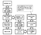
上記構成の機能水発生器の動作について説明する。図7は、機能水発生器の動作内容の概略を説明するための図である。先ず、給水口1aから一槽式の電解容器1内に水Wが供給される。使用する水Wとしては、普通の水道水を用いることができる。具体的に、例えば、大阪府八尾市の水道水(pH=7.5、硬度約50mg/L)を用いた場合、水500mLに対し、電流値:500mA、電極サイズ:150mm×100mm、電極間距離:15mmにて電流を印加した特、電圧値:30V以下という比較的低い電圧値で電気分解を行うことができる。
これにより、ユーザーのランニングコストを低減することが可能である。なお、水道水単独での使用も可能であるが、必要に応じて、KCl、NaClなどの電解添加剤を0.1~1wt%程度添加して電気分解を促進(電圧値を低下)させても良い。
電解容器1内が満水になって電気分解部4の電極9及び10が水に浸漬した状態で電気分解が実施される。電気分解は、図3に示すように、白金電極9を陽極、炭素電極10を陰極として実行される。電気分解により生成した機能水は酸性化する。具体的に、電気分解を行う水が500mlの場合、500mA、電極サイズ:150mm×100mm、電極間距離:15mmで4分間電気分解を行うことで、pH=3.0~3.2程度の酸性の機能水が得られる。
なお、本実施形態の機能水発生器は、バッチ方式で電気分解が行われる。バッチ方式とは、電解容器に所定量の水を加えた後は実質的に電解容器内の水の出し入れを行うことなく、電気分解を実行することを意味する。
電気分解時は、陽極である白金電極9から酸素ガスを放出し、残った水素イオンが水中に遊離することで、下記反応式(1)に示すように酸性化する。

一方、陰極である炭素電極10では水道水等の水中に溶存しているMgイオン、Caイオンなどの硬度成分を下記反応式(2)で示すように炭素電極の有する多孔質吸着面を利用して電気二重層イオンとして効果的に吸着させている。

なお、本実施形態では、図3及び図5に示すように、炭素電極10よりも白金電極9が上側に配置されているため、電気分解により白金電極9から酸素ガスが発生しても発生した酸素ガスが炭素電極10に付着して電気分解を阻害するおそれはない。ただ、白金電極の下面側には酸素ガスがたまりやすくなる。
そこで、より効率的に電気分解を行うため、白金電極にスリットを設けたり、短冊状に形成した複数の白金電極を水平方向に間隔をおいて並べたり、若しくはメッシュ状にすることでガスを溜まりにくくすることができるとともに、白金電極上で生成する酸アルカリイオンを白金電極の上下で効果的に対流させることができる。さらに、電解容器内の水を撹拌する装置、あるいは、電気分解部の電極を振動又は揺動させる装置、超音波振動子など、電気分解部に付着する気泡を除去する気泡除去装置を用いれば、電極9,10に接触する水の面積が増加し、さらには電解容器内の水が均質化されることによって、より効率よく電気分解を行うことができる。
また、電解容器1内の水をより効率良く対流させるため、電極9,10の端部と電解容器1の間には、接触電極11に接続される電極基端部を除いて最低5mm以上の間隔が開いていることが望ましい。こうすることで、気泡除去装置の作用と相まって電解容器1内の対流がより起こりやすくなり、より効率よく電気分解を行うことができる。
上記電気分解により、生成した機能水中の硬度成分濃度を低減することができ、得られた機能水を噴霧式の加湿器に使用することで、家具や窓ガラスにカルシウム塩やマグネシウム塩が付着するのを抑制することが可能となる。また、機能水を加熱式の加湿器に使用することで、加湿フィルタ等に硬度成分がスケールとして堆積するのを抑制することができる。
機能水のpHは2.5以上5.0以下であることが好ましい。この機能水を拡散部2においてミスト化することによって、機能水のpHを変動させることなく、空気中又は人体に噴射することが可能となり、空気中に噴射した際には酸性の機能水の殺菌効果によって細菌感染の予防が可能となる。肌などに噴射した際は、アストリンゼン効果による消毒効果、皮膚等の活性化、肌の引き締め効果を奏する。なお、ミストMは、たとえば、超音波振動子、あるいはエアポンプによる霧吹きの原理を用いて発生させることができる。
また、拡散部2にスチーム発生装置を用いることで、水の沸騰で機能水のpHは多少中性側にシフトするが、元になる機能水は電気分解により硬度成分を低下させた水であるため、水道水をスチームに使用した場合に問題となる硬度成分(スケール)の噴出口付近への堆積を防止し、噴出口が詰まって噴出しなくなるといったトラブルの発生を抑制することができる。
従って、水道水のみの利用であっても、特段のメンテナンス無しに、長期間スチームの稼働が可能というユーザーメリットを奏する。無論、スチーム噴射により、空気中には加湿効果、肌などに噴射した際は、温スチームによる肌の潤い改善の効果を奏する。なお、スチーム発生の為には水を沸騰化させる必要があるが、これは例えばセラミックヒーター等の昇熱器により1段回、若しくは多段階で昇熱、沸騰化して良い。なお、散水槽はミスト発生槽、スチーム発生槽のどちらであっても良く、また、双方を備えたものであっても良い。
なお、前記電解容器1内及び拡散部2のいずれの水中にも卑金属を含まないことが望ましい(ここで、卑金属とは例えば白金、金、パラジウム、ロジウム、イリジウム等、酸性水である機能水に対して安定な金属以外を指すものとする)。これは鉄や銅等の金属材料が機能水の流路に存在すると、機能水と酸化還元反応を起こすことで機能水のpHが中性化してしまい、所望のpHの機能水が取り出せなくなるからである。従って、上述のヒーターにおいても、セラミックヒーター等、機能水と反応を起こしにくい材料であることが望ましい。
制御装置14は、電解容器1内の水に所定量の電流が流れた時点で電気分解を終了し、開閉弁7を開放することで、生成した機能水は排出部3を通って拡散部2に導入される。拡散部2では、機能水をミスト化又はスチーム化する装置が設けられており、制御装置14によってこの装置の運転が開始され、これによって機能水がミストM又はスチームの状態で空気中に拡散する。
一方、機能水の大部分が排出された後の電解容器1内には、電極9及び10の全体が浸漬するだけの量の機能水が残留する。すなわち、電極9及び10の全体が浸漬するだけの機能水が残留する高さに排水口15が形成され、開閉弁7を開放するだけで必要な量の機能水が残留するようになっている。
電解容器1では、電極9及び10が機能水に浸漬した状態で、図4に示すように、制御装置14によって電気分解時とは逆向きの電流を流すことにより、電極洗浄が行われる。この場合、炭素電極10が陽極となり、白金電極9が陰極となる。これにより、陽極である炭素電極10では電極表面に付着した硬度成分Mが下記反応式(3)に示すようにM2+となって水中に溶出する。

一方、陰極となる白金電極の表面では、下記反応式(4)で表される反応が起こり、水素ガス(H2)と水酸化イオン(OH-)が発生する。すなわち、上記反応により残留水をアルカリ水化でき、炭素電極に吸着したCaイオン、Mgイオンなどの硬度成分を溶出させることが可能である。なお、ここで残留水に印加する電流値は機能水の残留量に依らず、上記機能水生成時と同等の電気量を流せば良く、例えば500mAで4分間、又は、250mAで8分間等であれば良い。
本実施形態では、電気分解、機能水の排水及び電極洗浄は、制御装置14によって自動的に実行される。これにより、ユーザーの利便性を高めることができるほか、自動的に電極を良好な状態に維持することができる。ただ、電気分解後に手動で機能水の排水及び電極洗浄を行うようにしてもよい。

上記陽極及び陰極は一対以上であれば良く、例えば、陽極と陰極とを垂直方向に間隔をおいて交互に配置してもよい。また、炭素電極の硬度成分の溶出は、電解容器内で機能水を生成する都度行っても良いし、5回乃至は10回程度機能水を生成した後、行なっても良い。また、排出部3は、途中で分離可能に設けられる。図1に示すように排出部3が一体に接続されているとき、すなわち、電解容器1が本体部5に装着されているときのみ排水口15から水を排出可能としている。一方、図3及び図4に示すように、排出部3を分離したとき、すなわち、電解容器1を本体部5から取り外したときは水が排出されない弁を用いるのが好ましい。
また、上記電気分解部4の電気分解に用いられる水としては、水道水を用いることが望ましい。これは、水道水には予めCaイオン、Mgイオンなどの硬度成分が含まれており、これらがイオン伝導に寄与するため、比較的低電圧で電気分解が可能となるからである。従って、通常の水道水により、比較的低い電圧値を用いた場合であっても低電圧(低電力)で電気分解を行うことができ、ユーザーのランニングコストを低減することができる。硬度成分溶存量が比較的低い地域などでは、便宜上、KCl、NaCl等の電解添加剤を微量添加(0.1~1wt%程度)しても良い。
なお、本実施形態では白金電極を陽極として電気分解を行うことで機能水を生成しているが、ここで陽極に用いる電極は溶解しない電極部材であればよく、カーボン等でも良いが、水の電気分解を効率的に行いやすい金属、例えば白金、金、パラジウム、ロジウム、イリジウムの内、いずれか1つの金属(またはその合金)が好適であり、例えばチタンからなる電極の表面を白金でコートしたものでもよい。
上記構成の機能水発生器においては、電極洗浄後の硬度成分が溶出した水は、次回の機能水生成までにユーザーで廃棄すれば良く、次回の使用直前に廃棄、新しい溶液の供給を行なっても良いが、硬度成分の電極への再付着を防止するため、毎回の使用後に廃棄することが望ましい。
図8、9は、本発明の第二実施形態を示す図であり、図8は電解容器が満水の状態の機能水発生器の模式図を示し、図9は電気分解により生成した機能水を拡散部に導入した状態の機能水発生器の模式図を示す。本実施形態においては、白金電極9にフロートを取り付けた点が図1における機能水発生器と異なる点であり、他の構成は図1と同様とされている。
本実施形態の機能水発生器は、電解容器1中の陽極としての白金電極9の端部にフロート8を取付けることで、白金電極9について、液面に追従して位置が上下方向に移動可能とされる。すなわち、図8に示すように、電解容器1内に収容された水を電気分解する際には、白金電極9は水面に追従して電解容器1の上部まで上昇し、取水した水全体に対して電気分解して機能水を生成する。
排水口15から機能水を排水すると、図9に示すように、機能水の水面に追従して白金電極9が下降する。そして、電解容器1内に残留した水に対して機能水生成時とは逆向きの電流を印加することで、機能水生成時に活性炭電極に最大限吸着された硬度成分を最小限の水量にて溶出除去することができる。
図10は、実際に電極間隔を変えた場合の機能水の生成時間を比較したものである(電解条件:水300mLに対し、電極サイズ:90mm×70mm、電極間距離:10mmにて300mA、500mA電流を印加)。
陽極固定時(電極間隔:10mm)に対し、水面に追従させる(電極間隔:25mm、電極位置=液面下3mm)ことで、例えばpH4.5の機能水を生成するための時間を比較すると、500mAの電流印加の場合、約8秒、300mAの電流印加の場合、電流値にも依るが、約12秒の時間短縮(6~8%程度)が見られる。これは主として、機能水生成時生成した水素イオンを白金電極の下方向にのみ拡散できるため、陽極で発生した水素イオンが陽極-陰極間の伝導に関与し電圧を下げる(電気伝導度を上げる)ことが可能となり、これによって電気分解の効率を向上させることができるためと考えられる。
この様に、陽極を水面に追従させて動かすことで、電解時間の短縮化を図ることができる。また、機能水生成時に活性炭電極に最大限吸着された硬度成分を最小限の水量にて溶出除去することができる。なお、陽極は、水面表面から1mm~10mm下方に位置するように水面の変動に追従して移動するようにすればよい。フロートは、電解容器壁面を摺動しながら上下方向に移動可能となる様、平滑な部材からなることが好ましい。また、印加する電流値が大きくなるに従って、短縮される時間は短くなる。その一方で、電極の寿命は短くなるため、電流密度としては120A/m2以下とすることが望ましい。
図11は、本発明の第三の実施形態を説明するための模式図である。本実施形態においては、排出部3を分離して電解容器1を本体部5から取り外すと、排水口15は自動的に閉鎖される。なお、排水口15は手動で開放可能に設けられ、給水時に給水口1aとして機能する。
すなわち、給水時に排水口15は、上向きにされて手動で開放された後に、給水口1aとして電解容器1内に水Wが供給される。水Wとしては、普通の水道水を用いることができる。電解容器1内を満水にした後、電解容器1を元の状態(排水口15が横向きになった状態)にして本体部5に装着する。着脱時の電気的接触を取るため、電解容器1側、本体部5側の双方に接点を設け、電気的な接触を取るようにする。
電解容器1を本体部5に装着することにより、すなわち、排出部3が一体に接続された状態で排水口15は開放状態となり、排出部3の開閉は開閉弁7の開閉によって制御される。なお、本体部5から電解容器1に給電され、電気分解が開始される。1~3分程度の電気分解を行うことで、pH=2.5~5.0程度の機能水が生成する。
電気分解完了後、機能水発生器本体に設けられた開閉弁7をOPENにすることで、電解容器1において生成された機能水は排出部3を介して本体部5に導入される。(機能水発生器本体に機能水を導入した後、電解容器内に逆向き電流を印加することにより、残留水に対し、活性炭電極に付着した硬度成分を溶出除去することが可能である)。
すなわち、本実施形態では、排水口は、給水時に上向きにされて給水口として機能するため、電気分解部の陽極及び陰極は立てた状態となり、手の震えなどに対して水のこぼれにくい安定感のある給水が可能である。また、電極洗浄後、電解容器を本体部から取り外した状態で、硬度成分が溶解した残留水を廃棄する時、排水口は下向きとされて廃水口として機能する。このとき、電気分解部の陽極及び陰極は立てた状態となり、残留水は、排水口に向かって電極の表面を沿うように流れるため、電極表面に残った硬度成分などを効果的に除去することが可能となる。
図12~図15は、本発明の第四の実施形態を説明するための図である。本実施形態では、電気分解により生成した機能水W1を貯蔵する機能水貯蔵部と、電極洗浄により生成するアルカリ水を貯蔵するアルカリ水貯蔵部とが別々に形成され、排出部3の配管6が電解容器1の底部に接続されている点が特徴とされ、その他の構成は第一の実施形態と同様とされる。
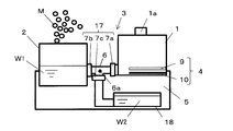
図12は、本実施形態の機能水発生器の構成を示す図であり、電解容器内に給水した状態を示す模式図である。なお、本実施形態では第一実施形態における拡散部2が機能水を貯蔵する機能水貯蔵部として機能する。図13は、図12の機能水発生器において生成した機能水を電解容器から排水して機能水貯蔵部(=拡散部)に導入した状態を示す模式図である。図14は、図13の機能水発生器において電解容器内に残存した機能水を用いて電極洗浄を行い、生成したアルカリ水をアルカリ水貯蔵部に導入した状態を示す模式図である。
本実施形態の機能水発生器は、水W0を電解して生成する機能水W1を貯蔵する機能水貯蔵部(=拡散部)2と、電極洗浄によって生成するアルカリ水W2を貯蔵するアルカリ水貯蔵部18とを備えている。なお、アルカリ水貯蔵部18は本体部5に対して着脱可能に取り付けられている。排出部3は、電解容器1から機能水W1又はアルカリ水W2を排出して機能水貯蔵部2又はアルカリ水貯蔵部18に導入するように形成される。
具体的に、排出部3は、一端側が電解容器1に接続され、他端側が分岐部6aを介して分岐形成された配管6と、配管6に介装される流路切替部材17とから構成され、配管6の他端側に機能水貯蔵部2と、アルカリ水貯蔵部18とが接続される。配管6の一端側は、電解容器1の底部に接続される。流路切替部材17は、分岐部6aと電解容器1の間の配管に介装される開閉弁7aと、分岐部6aと機能水貯蔵部2との間の配管に介装される開閉弁7bと、分岐部6aとアルカリ水貯蔵部18との間の配管に介装される開閉弁7cによって構成されている。制御装置14は、流路切替部材17の各開閉弁7a~7cの開閉及びミスト発生装置の運転を制御する。
上記構成の機能水発生器の動作について説明する。図15は、本実施形態の機能水発生器の動作内容の概略を説明するための図である。先ず、制御装置14は、第一実施形態のときと同様にして電解容器1内の水の電気分解を実行する。そして、水に所定量の電流が流れた時点で電気分解を終了し、流路切替部材17の開閉弁7a~7cを開閉制御することで、図13に示すように、生成した機能水W1を、排出部3を通じて機能水貯蔵部2に導入する。具体的には、開閉弁7cを閉じた状態で、開閉弁7a及び7bを開放する。
これにより、電解容器1とアルカリ水貯蔵部18との間の流路が閉じた状態のまま、電解容器1と機能水貯蔵部2との間の流路が開放され、電解容器1内の機能水W1は、機能水貯蔵部2内の機能水W1と水面の高さが同じになるまで、機能水貯蔵部2に流入する。このとき、電気分解部の両電極9及び10の全体が浸漬する量の機能水W1が電解容器内に残存するように機能水貯蔵部2の位置及び大きさを調整すればよい。
これにより、開閉弁7a及び7bを開放して排出部3から電解容器1内の水Wを排水しても、図13に示すように、白金電極9及び炭素電極10全体が水Wに浸漬した状態で保たれる。機能水貯蔵部2はもともと拡散部であることから、ここに収容された機能水W1は、制御装置14によりミスト化されて空気中に拡散する。
制御装置14は、前述のごとく、電気分解時とは逆向きで酸性水生成時と同等程度の電気量の電流を流すことにより、電極洗浄を実行する。なお、アルカリ水のpH管理を確実にすべく、機能水貯蔵部にはpHセンサ、若しくは伝導度センサ等を施しモニターすることが望ましい。なお、アルカリ水W2のpHは、9.0以上11.5以下であることが好ましい。
電極洗浄が終了した後、開閉弁7bを閉じた状態のまま、開閉弁7a及び7cを開放する。このとき、アルカリ水貯蔵部18の底面が電解容器1の底面よりも低くなるようにすることで、ポンプ等を使用しなくとも重力を利用して電解容器1からアルカリ水貯蔵部18にアルカリ水W2を導入することができる。アルカリ水貯蔵部18に貯蔵されたアルカリ水W2は、洗顔に使用してもよいし、アルカリ水貯蔵部18に溜まった量が多いときは廃棄してもよい。
アルカリ水W2を皮膚洗浄用として使用すれば、アルカリ水中の水酸化イオン(OH-)は肌表面の油脂と下記反応式(5)に示すように、いわゆるケン化反応を起こすことにより界面活性作用を奏して、洗浄効果を発揮する。このように、アルカリ水W2を有効利用することで機能水発生器の利便性をより高めることが可能となる。なお、式中、Na+は肌上に存在するナトリウムイオンを示している。

本実施形態では、白金電極9と炭素電極10とが垂直方向に間隔をおいて平行に対向配置しているため、白金電極9及び炭素電極10全体が機能水W1に浸漬した状態を保つ場合に、機能水貯蔵部2に排出する機能水量を多くすることが可能となる。すなわち、利用できる機能水W1量を多くすることが可能となる。
さらに、電極洗浄によって生成するアルカリ水W2量を抑えることができ、アルカリ水貯蔵部18に電極洗浄複数回分のアルカリ水W2を貯蔵することが可能となる。したがって、電極洗浄を行うごとに電解容器内に残存したアルカリ水W2を取り出すという手間を省くことができ、利便性の高い機能水発生器を得ることができる。
以上の実施形態の説明から明らかな通り、本発明の機能水生成器は、電解容器内に陽極及び陰極から成る電気分解部が設けられ、前記電解容器内に供給された水を前記電気分解部にて電気分解することにより機能水を生成した後、電解容器から前記機能水を排出する際に、前記陽極及び陰極の両電極が浸漬するように電解容器内に機能水を残留させ、前記電気分解部の電極に対して機能水生成時とは逆向きの電流を流すことにより、機能水生成時に電極に付着した硬度成分を水中に溶出させる電極洗浄を行う機能水発生器であって、前記電気分解により生成した機能水を貯蔵する機能水貯蔵部と、前記電極洗浄により生成するアルカリ水を貯蔵するアルカリ水貯蔵部とが前記電解容器とは別に形成されたことを特徴とする。
このような構成とすることにより、電解容器内において電気分解により生成した機能水を機能水貯蔵部に貯蔵するだけでなく、電極洗浄により生成したアルカリ水をアルカリ水貯蔵部に貯蔵することで、電極洗浄を行うごとに電解容器内に残存したアルカリ水を取り出すという手間を省くことができ、利便性の高い機能水発生器を得ることができる。
電解容器内のアルカリ水をアルカリ水貯蔵部で貯蔵するには、電解容器にアルカリ水を排出する排出部を設けて、この排出部にアルカリ水貯蔵部を接続すればよい。なお、排出部は、機能水を排出する排出部とは別個に形成することもできるが、機能水及びアルカリ水を排出可能としてもよい。
機能水及びアルカリ水を電解容器から排出する排出部としては、具体的に、一端側が前記電解容器に接続され、他端側が分岐部を介して分岐形成された配管と、前記配管に介装される流路切替部材とから構成され、前記配管の他端側に、前記機能水貯蔵部と、前記電極洗浄後に生成するアルカリ水を貯蔵するアルカリ水貯蔵部とが接続された構成とすることができる。これにより、機能水発生器全体として構造を簡単にすることができる。
上記構成の排出部において、配管の一端側が前記電解容器の底部に接続され、前記排出部が閉鎖された状態で前記電解容器に供給された水を電気分解した後に、前記流路切替部材により、前記電解容器とアルカリ水貯蔵部との間の流路を閉じた状態のまま、電解容器と機能水貯蔵部との間の流路を開放したときに、前記電気分解部の両電極全体が浸漬する量の機能水が電解容器内に残存するように前記機能水貯蔵部の位置を設定してもよい。
上記構成によれば、流路切替部材によって流路を切り替えるだけで電極洗浄に必要な量の機能水を電解容器に残存させることができる。なお、機能水貯蔵部の位置を設定するとは、具体的には、任意の大きさの機能水貯蔵部を用いる際に、その位置(高さ)を調整することにより、前記電解容器とアルカリ水貯蔵部との間の流路を閉じた状態のまま、電解容器と機能水貯蔵部との間の流路を開放したときに電解容器内の機能水の水面の高さが電気分解部の両電極全体が浸漬する高さで、機能水貯蔵部の水面の高さとバランスするようにすればよい。
さらに、上記排出部において、上記構成に加えて、電極洗浄を行った後に、前記流路切替部材により、前記電解容器と機能水貯蔵部との間の流路を閉じた状態のまま、電解容器とアルカリ水貯蔵部との間の流路を開放したときに、電解容器内のアルカリ水がアルカリ水貯蔵部に流入するようにアルカリ水貯蔵部の位置を設定してもよい。
具体的には、電解容器の底面よりも、アルカリ水貯蔵部の底面が低くなるように調整する。好ましくは、電解容器底面よりもアルカリ水貯蔵部全体が低い位置になるように調整する。これにより、ポンプ等を使用しなくとも重力を利用して電解容器からアルカリ水貯蔵部にアルカリ水を導入することができる。
電気分解部の電極は、陽極と陰極とが垂直方向に平行に対向配置してもよい。これにより、電極の厚み方向が垂直方向となり、電極を立てた状態に比べて電解容器内に占める電気分解部の容積は小さくて済む。したがって、電極洗浄の際に、残存させる機能水量を少なくすることが可能となる。これによって、1回の電極洗浄で生成するアルカリ水量を低減することができ、アルカリ水貯蔵部に溜まったアルカリ水を廃棄する手間を少なくすることができる。
得られたアルカリ水を皮膚洗浄用として使用すれば、前述のごとく、アルカリ水中の水酸化イオン(OH-)は肌表面の油脂とケン化反応を起こし、反応生成物は界面活性作用を有することから洗浄効果を発揮する。このように、アルカリ水を有効利用することで機能水発生器の利便性をより高めることが可能となる。
アルカリ水貯蔵部からアルカリ水を皮膚に適用する際は、液状のまま直接皮膚に適用してもよいし、ミスト状にして局所的に皮膚に吹きかけるようにしてもよい。なお、アルカリ水によって皮膚洗浄した後は、機能水を皮膚に適用するのが好ましい。すなわち、アルカリ水で皮膚洗浄して皮膚上のpHがアルカリ性に傾いた状態では、皮膚上で雑菌が繁殖しやすい環境となる。したがって、最終的に、皮膚に機能水を適用し、皮膚のpHを酸性に傾けることで皮膚上における雑菌の繁殖を抑えることができる。
以上詳述したように、本発明の機能水発生器で得られた機能水を皮膚に適用する場合、アルカリ水による皮膚洗浄を行わずに、機能水のみを皮膚に適用するか、アルカリ水で皮膚洗浄を行うときには、その後で機能水を皮膚に適用するのが好ましい。
以上、本発明の実施形態につき説明したが、本発明の範囲はこれに限定されるものではなく、発明の趣旨を逸脱しない範囲で種々の変更を加えて実施することができる。たとえば、本実施形態では、白金電極9は炭素電極10よりも上側に配されているが、これに限らず、図6に示すように、炭素電極10を白金電極9よりも上側に配することも可能である。これにより、電気分解部を内部に設けた容器を洗浄する際、洗浄水で炭素電極をより直接的に洗い流すことが可能である。
水中の硬度成分は活性炭表面の白金電極対向面に多くが付着するため、水道水等の洗浄水で電解容器を洗い流す時、洗浄水からの水圧が直接的に炭素電極に掛かり、活性炭表面を効果的に洗うことができるため、残存したアルカリ水成分、残存した硬度成分をより効果的に洗い流すことが可能である。
また、炭素電極を上に配置することにより、電気分解される水はすべて炭素電極を通過することになるため、炭素電極の吸着作用により、水中の微粒子等のホコリ成分を吸着でき、水の清浄化も図ることができる。なお、効果的に洗浄水で炭素電極を洗い流すため、炭素電極はできるだけ多孔質であるものが好適であり、また、厚みは4mm以下であることが望ましい。
なお、より効率的に電気分解を行うため、炭素電極や白金電極にスリットを設けたり、短冊状に形成した複数の電極を水平方向に間隔をおいて並べたり、若しくはメッシュ状にすることで、電極で生じたガスを溜まりにくくすることができるとともに、白金電極上で生成する酸アルカリイオンを電極の上下で効果的に対流させることができる。
また、本実施形態では流路切替部材17として、開閉弁7a~7cを使用したが、これに限らず、たとえば、分岐部6aに三方弁を設置してもよい。さらに、本実施形態では、電解容器1の位置を基準として、機能水貯蔵部2及びアルカリ水貯蔵部18の位置を設定し、開閉弁7a~7cを開閉制御することで、重力を利用して機能水W1及びアルカリ水W2をそれぞれ機能水貯蔵部2及びアルカリ水貯蔵部18に導入するようにしているが、これに限らず、たとえば、電解容器1内に水量検知センサを設け、ポンプによって所定量の機能水W1及びアルカリ水W2を排出するようにしてもよい。
また、アルカリ水貯蔵部18は硬度成分(スケール)が析出しやすく、また、雑菌も繁殖しやすいため、適宜、機能水貯蔵部2からアルカリ水貯蔵部18に酸性水を導入して、スケールの溶出、殺菌を行うモードを設けても良い。
1 電解容器
2 拡散部
3 排出部
4 電気分解部
5 本体部
6 配管
7 開閉弁
8 フロート
9 白金電極
10 炭素電極
11 接触電極
12 スイッチング回路
13 定電流発生源
14 制御装置
15 排水口
17 流路切替部材
18 アルカリ水貯蔵部
2 拡散部
3 排出部
4 電気分解部
5 本体部
6 配管
7 開閉弁
8 フロート
9 白金電極
10 炭素電極
11 接触電極
12 スイッチング回路
13 定電流発生源
14 制御装置
15 排水口
17 流路切替部材
18 アルカリ水貯蔵部
Claims (12)
- 電解容器内に陽極及び陰極から成る電気分解部が設けられ、前記電解容器内に供給された水を前記電気分解部にて電気分解することにより機能水を生成した後、電解容器の排水口から前記機能水を排出する際に、前記陽極及び陰極の両電極が浸漬するように電解容器内に機能水を残留させ、前記電気分解部の電極に対して機能水生成時とは逆向きの電流を流すことにより、機能水生成時に電極に付着した硬度成分を水中に溶出させる電極洗浄を行う機能水発生器であって、前記陽極と陰極とが垂直方向に平行に対向配置されたことを特徴とする機能水発生器。
- 前記電気分解部の陽極が陰極よりも上側に配されていることを特徴とする請求項1に記載の機能水発生器。
- 前記陽極が電解容器内の水面に追従して上下方向に移動可能であることを特徴とする請求項2に記載の機能水発生器。
- 前記電気分解部の陽極にフロートを取り付けることを特徴とする請求項3に記載の機能水発生器。
- 前記電気分解部の陰極が陽極よりも上側に配されていることを特徴とする請求項1に記載の機能水発生器。
- 前記電解容器内に、前記電気分解部に付着する気泡を除去する気泡除去装置が設けられたことを特徴とする請求項1~5のいずれかに記載の機能水発生器。
- 前記電解容器内において、陽極及び陰極の端部は電極基端部を除いて前記電解容器の内壁から5mm以上離れていることを特徴とする請求項1~6のいずれかに記載の機能水発生器。
- 前記排水口から排出された機能水をミスト又はスチームの形で空気中に放出する拡散部を備えたことを特徴とする請求項1~7のいずれかに記載の機能水発生器。
- 前記電解容器内及び拡散部のいずれの水中にも卑金属を含まないことを特徴とする請求項1~8のいずれかに記載の機能水発生器。
- 前記電解容器を着脱可能に保持する本体部が設けられ、前記排水口は、電解容器が本体部から取り外された状態で、電解容器内に給水するための給水口として機能することを特徴とする請求項1~9のいずれかに記載の機能水発生器。
- 空気の清浄化又は加湿用途として用いられることを特徴とする請求項8又は9に記載の機能水発生器。
- 美容用途として用いられることを特徴とする請求項1~11のいずれかに記載の機能水発生器。
Priority Applications (2)
| Application Number | Priority Date | Filing Date | Title |
|---|---|---|---|
| US14/425,368 US20150225265A1 (en) | 2012-09-07 | 2013-09-03 | Functional water generator |
| CN201380044908.6A CN104603065A (zh) | 2012-09-07 | 2013-09-03 | 功能水发生器 |
Applications Claiming Priority (6)
| Application Number | Priority Date | Filing Date | Title |
|---|---|---|---|
| JP2012197893 | 2012-09-07 | ||
| JP2012-197893 | 2012-09-07 | ||
| JP2012-197896 | 2012-09-07 | ||
| JP2012197896A JP2014050809A (ja) | 2012-09-07 | 2012-09-07 | 機能水発生器 |
| JP2012-255094 | 2012-11-21 | ||
| JP2012255094A JP2014065966A (ja) | 2012-09-07 | 2012-11-21 | 機能水発生器 |
Publications (1)
| Publication Number | Publication Date |
|---|---|
| WO2014038525A1 true WO2014038525A1 (ja) | 2014-03-13 |
Family
ID=50237134
Family Applications (1)
| Application Number | Title | Priority Date | Filing Date |
|---|---|---|---|
| PCT/JP2013/073605 Ceased WO2014038525A1 (ja) | 2012-09-07 | 2013-09-03 | 機能水発生器 |
Country Status (1)
| Country | Link |
|---|---|
| WO (1) | WO2014038525A1 (ja) |
Cited By (2)
| Publication number | Priority date | Publication date | Assignee | Title |
|---|---|---|---|---|
| WO2022264808A1 (ja) * | 2021-06-14 | 2022-12-22 | パナソニックIpマネジメント株式会社 | 電解水散布装置 |
| CN115507493A (zh) * | 2021-06-23 | 2022-12-23 | 重庆美的制冷设备有限公司 | 空气处理组件及其控制方法、空气处理装置和空调器 |
Citations (3)
| Publication number | Priority date | Publication date | Assignee | Title |
|---|---|---|---|---|
| JPH0671299A (ja) * | 1992-08-28 | 1994-03-15 | Fujita Corp | 濃縮装置 |
| JP2006095502A (ja) * | 2004-09-28 | 2006-04-13 | Takanobu Deguchi | ミスト発生装置、還元水ミスト雰囲気形成装置、および美顔器 |
| JP2010117080A (ja) * | 2008-11-13 | 2010-05-27 | Tanah Process Co Ltd | 加湿器 |
-
2013
- 2013-09-03 WO PCT/JP2013/073605 patent/WO2014038525A1/ja not_active Ceased
Patent Citations (3)
| Publication number | Priority date | Publication date | Assignee | Title |
|---|---|---|---|---|
| JPH0671299A (ja) * | 1992-08-28 | 1994-03-15 | Fujita Corp | 濃縮装置 |
| JP2006095502A (ja) * | 2004-09-28 | 2006-04-13 | Takanobu Deguchi | ミスト発生装置、還元水ミスト雰囲気形成装置、および美顔器 |
| JP2010117080A (ja) * | 2008-11-13 | 2010-05-27 | Tanah Process Co Ltd | 加湿器 |
Cited By (4)
| Publication number | Priority date | Publication date | Assignee | Title |
|---|---|---|---|---|
| WO2022264808A1 (ja) * | 2021-06-14 | 2022-12-22 | パナソニックIpマネジメント株式会社 | 電解水散布装置 |
| CN117425504A (zh) * | 2021-06-14 | 2024-01-19 | 松下知识产权经营株式会社 | 电解水散布装置 |
| CN115507493A (zh) * | 2021-06-23 | 2022-12-23 | 重庆美的制冷设备有限公司 | 空气处理组件及其控制方法、空气处理装置和空调器 |
| CN115507493B (zh) * | 2021-06-23 | 2025-06-27 | 重庆美的制冷设备有限公司 | 空气处理组件及其控制方法、空气处理装置和空调器 |
Similar Documents
| Publication | Publication Date | Title |
|---|---|---|
| JP2014065966A (ja) | 機能水発生器 | |
| CN104603065A (zh) | 功能水发生器 | |
| JP3619828B2 (ja) | 電解用電極及びその製造方法及び電解用電極を用いた電解方法及び電解水生成装置 | |
| KR100884879B1 (ko) | 공기 제균 장치 | |
| JP2006097311A (ja) | 水洗トイレ及び水洗トイレの脱臭方法 | |
| CN107109828B (zh) | 自动水龙头装置 | |
| KR101156121B1 (ko) | 공기제균장치 | |
| JPH03251625A (ja) | 加湿器 | |
| JP2014050809A (ja) | 機能水発生器 | |
| CN107109830A (zh) | 水龙头装置 | |
| WO2014038525A1 (ja) | 機能水発生器 | |
| JP4401695B2 (ja) | 加湿装置 | |
| JP2016083600A (ja) | 機能水生成装置 | |
| JP2012196643A (ja) | 次亜塩素酸水等の生成装置 | |
| JP2012052166A (ja) | 塩徐放用カートリッジを備えた電解水生成装置、及びこの電解水生成装置を備えた除菌装置若しくは空気清浄装置 | |
| JP6223112B2 (ja) | 空気清浄装置および空気調和機 | |
| JP2011177293A (ja) | 空気除菌装置 | |
| JP2009005747A (ja) | 洗浄装置 | |
| JPH1119648A (ja) | 殺菌装置 | |
| CN211781517U (zh) | 一种具有臭氧水超声波雾化装置的空调 | |
| JP3804519B2 (ja) | 電解水生成装置 | |
| JP2005313096A (ja) | 携帯用電解水生成器 | |
| JP2015226598A (ja) | 除菌性空気清浄機 | |
| JP2017158961A (ja) | 次亜塩素酸水入り容器、及び次亜塩素酸水に香りを付ける方法 | |
| JP4721921B2 (ja) | 空気除菌装置 |
Legal Events
| Date | Code | Title | Description |
|---|---|---|---|
| 121 | Ep: the epo has been informed by wipo that ep was designated in this application |
Ref document number: 13835897 Country of ref document: EP Kind code of ref document: A1 |
|
| WWE | Wipo information: entry into national phase |
Ref document number: 14425368 Country of ref document: US |
|
| NENP | Non-entry into the national phase |
Ref country code: DE |
|
| 122 | Ep: pct application non-entry in european phase |
Ref document number: 13835897 Country of ref document: EP Kind code of ref document: A1 |