WO2014034344A1 - 回転電機 - Google Patents
回転電機 Download PDFInfo
- Publication number
- WO2014034344A1 WO2014034344A1 PCT/JP2013/070410 JP2013070410W WO2014034344A1 WO 2014034344 A1 WO2014034344 A1 WO 2014034344A1 JP 2013070410 W JP2013070410 W JP 2013070410W WO 2014034344 A1 WO2014034344 A1 WO 2014034344A1
- Authority
- WO
- WIPO (PCT)
- Prior art keywords
- permanent magnet
- slot
- rotor core
- rotor
- diameter side
- Prior art date
- Legal status (The legal status is an assumption and is not a legal conclusion. Google has not performed a legal analysis and makes no representation as to the accuracy of the status listed.)
- Ceased
Links
Images


Classifications
-
- H—ELECTRICITY
- H02—GENERATION; CONVERSION OR DISTRIBUTION OF ELECTRIC POWER
- H02K—DYNAMO-ELECTRIC MACHINES
- H02K1/00—Details of the magnetic circuit
- H02K1/06—Details of the magnetic circuit characterised by the shape, form or construction
- H02K1/22—Rotating parts of the magnetic circuit
- H02K1/27—Rotor cores with permanent magnets
- H02K1/2706—Inner rotors
- H02K1/272—Inner rotors the magnetisation axis of the magnets being perpendicular to the rotor axis
- H02K1/274—Inner rotors the magnetisation axis of the magnets being perpendicular to the rotor axis the rotor consisting of two or more circumferentially positioned magnets
- H02K1/2753—Inner rotors the magnetisation axis of the magnets being perpendicular to the rotor axis the rotor consisting of two or more circumferentially positioned magnets the rotor consisting of magnets or groups of magnets arranged with alternating polarity
- H02K1/276—Magnets embedded in the magnetic core, e.g. interior permanent magnets [IPM]
- H02K1/2766—Magnets embedded in the magnetic core, e.g. interior permanent magnets [IPM] having a flux concentration effect
-
- H—ELECTRICITY
- H02—GENERATION; CONVERSION OR DISTRIBUTION OF ELECTRIC POWER
- H02K—DYNAMO-ELECTRIC MACHINES
- H02K1/00—Details of the magnetic circuit
- H02K1/06—Details of the magnetic circuit characterised by the shape, form or construction
- H02K1/22—Rotating parts of the magnetic circuit
- H02K1/28—Means for mounting or fastening rotating magnetic parts on to, or to, the rotor structures
Definitions
- the present invention relates to a rotating electrical machine.
- a rotating electric machine (a motor, a generator) using a permanent magnet is applied in an application which is required to be small, light and have high performance.
- a rotor of a rotating electrical machine using permanent magnets is provided with a rotor core formed in a cylindrical shape by laminating thin steel plates in the axial direction. By providing the holes for inserting the permanent magnets in the steel plate and laminating them, slots for inserting the permanent magnets are formed in the rotor core, and the permanent magnets are attached to the slots.
- the rotor core is fixed to the shaft that is the rotation axis, and forms the main component of the rotor.
- the arrangement of permanent magnets with respect to the rotor core can be broadly classified into surface magnet types and embedded magnet types.
- the surface magnet type as described in, for example, Patent Document 1, permanent magnets are attached to the outer peripheral surface of a rotor core at predetermined intervals.
- This surface magnet type rotor can effectively use the magnetic flux of the permanent magnet because the magnetic flux of the permanent magnet does not short circuit in the rotor core.
- the permanent magnet may be broken or separated by the centrifugal force, so it is not suitable for high-speed rotation applications.
- the eddy current loss may increase the temperature of the permanent magnet, resulting in a decrease in efficiency.
- the second permanent magnet is disposed on the inner diameter side thereof.
- the embedded magnet type motor prevents permanent magnet cracking and peeling due to centrifugal force because the closed hole in the rotor core, that is, the closed slot includes the permanent magnet. be able to.
- One pole of this rotor core is shown in FIG.
- This rotor structure has an advantage that eddy current loss can be reduced in addition to the prevention of permanent magnet breakage.
- two slots are provided in a V-shape, and a permanent magnet is embedded in each of them so that the rotor core between the poles is formed. The reluctance torque can be effectively used, and a compact, high-efficiency motor can be realized.
- the elastic mechanism is disposed in the slot provided in the rotor core, thereby integrating the permanent magnet and the rotor core and improving the rigidity of the rotor.
- Patent Document 3 also refers to an embedded magnet type rotor.
- a rotor structure in which a V-shaped slot is provided in a rotor core and two permanent magnets are embedded in the slot is the same as in Patent Document 2.
- the magnetic pole part and the yoke part of the rotor core located on the outer diameter side and the inner diameter side sandwiching the V-shaped slot are not connected to each other, and the hardenable nonmagnetic between the two permanent magnets in the slot By filling with a substance, a rotor is formed.
- the V-shaped slot is provided with a notch toward the outer periphery of the rotor core. Therefore, the slot is not a closed hole in the rotor core, but an open slot having an open portion toward the outer periphery of the rotor core is adopted.
- Patent Document 4 also refers to an embedded magnet type rotor.
- a rotor structure in which a V-shaped slot is provided in a rotor core and two permanent magnets are embedded in the slot is the same as Patent Documents 2 and 3.
- the slots provided in the rotor core are alternately laminated with a closed slot steel plate as described in Patent Document 2 and an open slot steel plate as described in Patent Document 3 to form a rotor core. It is formed.
- JP 2003-61280 A JP-A-9-308148 Japanese Patent Application Laid-Open No. 2-179253 JP, 2011-4480, A
- a general magnet embedded rotor is a so-called closed slot in which slots are provided in the shape of a hole in a rotor core as shown in Patent Document 2, a short circuit of magnetic flux occurs in the rotor core. Occur.
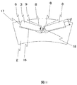
- permanent magnets on the outer diameter side as much as possible. For that purpose, it is necessary to arrange V-shaped slots on the outer diameter side as much as possible, but as a result, as shown in FIG. 12, narrow portions 20a and 20b are formed on the rotor core on the outer diameter side than the slots. It will be done.
- the narrow portions 20a and 20b need to have a certain size or more in order to prevent mechanical fracture.
- the use of the magnet torque is limited.
- the present invention provides a rotating machine that achieves high efficiency and strength reliability by suppressing short circuit of magnetic flux in the rotor core and arranging permanent magnets on the outer diameter side compared to the conventional embedded magnet type. Do.
- composition of a claim is adopted, for example.
- the present application includes a plurality of means for solving the above-mentioned problems, and an example thereof is a stator provided with a coil and a stator core, and the stator facing the stator with an air gap therebetween to rotate permanent magnets and rotations.
- a rotor comprising an iron core, wherein the permanent magnet is embedded in a V shape in a hole-like slot provided in the rotor core to form one pole;
- the slot is an open slot in which a part of the slot is opened toward the outer periphery of the rotor core, and the permanent magnet is attached to the open part of the slot It is characterized in that it has a supporting wedge structure.
- FIG. 1 is a perspective view showing a first structural example of a rotating electrical machine according to a first embodiment.
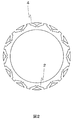
- Sectional drawing of the rotor core which shows the 1st structural example of the rotary electric machine by 1st Embodiment.
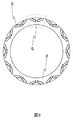
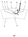
- Sectional drawing of the rotor core and permanent magnet which show the 1st structural example of the rotary electric machine by 1st Embodiment.
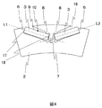
- Sectional drawing which expands and shows one magnetic pole part among the cross sections which show the 1st structural example of the rotary electric machine by 1st Embodiment.
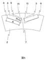
- Sectional drawing which expands and shows one magnetic pole part among the cross sections which show the structural example derived from the 1st structural example of the rotary electric machine by 1st Embodiment.
- Sectional drawing which expands and shows one magnetic pole part at the time of being filled with resin when the clearance gap between a permanent magnet and a rotor core is filled with resin among the cross sections which show the 1st structural example of the rotary electric machine by 1st Embodiment.
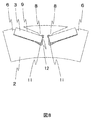
- Sectional drawing which expands and shows one magnetic pole part in the cross section which shows the 2nd structural example of the rotary electric machine by 1st Embodiment.
- Sectional drawing which expands and shows one magnetic pole part at the time of being filled with resin when the clearance gap between a permanent magnet and a rotor core is filled with resin among the cross sections which show the 2nd structural example of the rotary electric machine by 1st Embodiment.
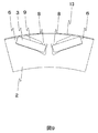
- Sectional drawing which expands and shows one magnetic pole part among the cross sections which show the structural example of the rotary electric machine by 2nd Embodiment.
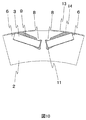
- Sectional drawing which expands and shows one magnetic pole part at the time of filling the clearance gap between a permanent magnet and a rotor core with resin among the cross sections which show the structural example of the rotary electric machine by 2nd Embodiment.
- Sectional drawing which expands and shows one magnetic pole part among the cross sections which show the structural example of the rotary electric machine by 3rd Embodiment.
- Sectional drawing which shows one magnetic-pole part among the sections of a rotor core in the rotor of the conventional embedded magnet type
- the schematic diagram which shows the whole rotary electric machine.
- the rotary electric machine 100 is disposed inside the case 110 as shown in FIG. 1 and includes a housing 112 and a stator 130 having a stator core 132 fixed to the housing 112, and the inside of the stator And a rotor 150 which is rotatably disposed.
- the case 110 is formed of an engine case and a transmission case.
- the rotary electric machine 100 is a three-phase synchronous motor with a built-in permanent magnet.
- the rotary electric machine 100 operates as a motor for rotating the rotor 150 by supplying a three-phase alternating current to the stator coil 138 wound around the stator core 132.
- the rotary electric machine 100 operates as a generator and outputs three-phase AC generated power. That is, the rotary electric machine 100 has both a function as an electric motor that generates a rotational torque based on electric energy and a function as a generator that generates electric power based on mechanical energy, and The functions can be selectively used.
- FIGS. 1 to 6 are perspective views showing a rotor core and a permanent magnet constituting an embedded magnet type rotor of a rotating electric machine
- FIG. 2 is a cross sectional view perpendicular to the axial direction of the rotor core of FIG. It is sectional drawing when a permanent magnet is embed
- 4 are cross-sectional views in which only an angle portion constituting one pole in FIG. 3 is enlarged.
- the embedded magnet type rotor 150 has a structure in which permanent magnets 3 are embedded in the rotor core 2.
- slots 4 which are holes for inserting permanent magnets, are provided in the rotor core 2 at intervals in the circumferential direction.
- the rotor core 2 is configured by laminating thin steel plates having the cross-sectional shape of FIG. 2 in the direction of the rotating shaft 1.
- a neodymium magnet, a samarium cobalt magnet, a ferrite magnet or the like is used as the permanent magnet 3.
- the structure example of this embodiment can be realized also by permanent magnets other than these.
- the permanent magnet 3 inserted in the slot 4 is arranged to open in a V shape from the rotation shaft 1 toward the outer periphery of the rotor core 2 (that is, radially outward), as shown in FIG.
- the intersection of the center line L1 and the center line L2 parallel to the long side of the cross section of the permanent magnet 3 does not coincide with the center of the shaft 1 of the rotor.
- the outer diameter side of the slot 4 is opened toward the outer periphery of the rotor core 2, and an open portion 19 is formed.
- the rotor core in the vicinity of the open portion 19 is provided with a wedge-shaped structure 6 and contacts the outer diameter side short side 17 of the cross section of the permanent magnet 3 to support the force acting on the permanent magnet by centrifugal force.
- the magnitude of the stress acting on the narrow portion 7 between the slots of the rotor core 2 is the same in the conventional closed slot structure. There is not much difference with the magnitude of the generated stress.
- the outer diameter side long side 9 of the permanent magnet 3 is in contact with the projection 8 provided in the slot 4 of the rotor core 2 at one point, and the outer diameter side long side 9 of the permanent magnet 3 and the rotor core There is no line contact (surface contact when considered in three dimensions).
- the projection 8 is provided closer to the short side 18 on the inner diameter side than the middle point 10 of the long side 9 on the outer diameter side.
- the protrusions 8 and the wedge-shaped structure 6 also play a role of facilitating the arrangement of the permanent magnet 3 in the position shown in FIG. 4 at the time of manufacture.
- FIG. 5 is also included in the scope of the present embodiment of the present invention.
- FIG. 6 by filling the space 11 between the permanent magnet 3 and the rotor core 2 with resin, it is possible to suppress the movement of the permanent magnet 3 at the time of operation of the rotary electric machine, and the mechanical reliability is high. A rotating electrical machine can be realized.
- FIG. 7 and 8 are cross-sectional views showing a second structural example of the rotating electrical machine according to the first embodiment of the present invention.
- the inner diameter side short side 18 of the permanent magnet 3 is in contact with the second projection 12 provided in the slot 4 of the rotor core.
- the permanent magnet 3 can be easily arranged in the position shown in FIG. 7 when manufacturing the rotor.
- centrifugal force F acts on permanent magnet 3 as shown by an arrow in FIG. 7
- moment M acts on permanent magnet 3 with projection 8 as a fulcrum, but second projection 12 makes this moment M It plays a supporting role with the boat-shaped structure 6.
- the resin is filled in the gap 11 on the inner diameter side of the permanent magnet 3 and the rotor core 2 so that the permanent magnet can be permanently positioned as shown in FIGS.
- the magnet 3 can be stably held.
- the slots are opened toward the outer periphery of the rotor core, there is no short circuit of the magnetic flux through the narrow portion on the slot outer diameter side of the rotor core.
- the permanent magnet can be disposed extremely on the outer diameter side, and the magnet torque can be utilized to the maximum.
- there is no narrow portion on the slot outer diameter side there is no need to worry about mechanical failure of the corresponding portion due to centrifugal force. Most of the centrifugal force acting on the permanent magnet during rotation is supported by the wedge-shaped structure provided in the vicinity of the slot opening, so the stress generated in the narrowing between the slots is within the tolerance without increasing the size. Can be reduced to
- the long outer side of the permanent magnet and the contact point of the rotor core are located on the outer diameter side of the middle point of the long side of the outer diameter, most of the centrifugal force acting on the permanent magnet is It is transmitted to the narrow portion between the slots of the rotor core through the contact point, and the wedge-shaped structure provided at the open portion of the slot reduces the effect of supporting the centrifugal force acting on the permanent magnet.
- the centrifugal force of the permanent magnet can be effectively supported by the wedge-shaped structure by providing the outer diameter side long side of the permanent magnet and the contact point of the rotor core on the inner side with respect to the middle point of the outer side long side. it can.
- FIG. 9 is a cross-sectional view showing a structural example of a rotating electrical machine according to a second embodiment of the present invention.
- FIG. 10 is a cross-sectional view showing a case where the gap between the permanent magnet 3 and the rotor core 2 of FIG. 9 is filled with a resin.
- the thin film 13 is formed on the outer periphery of the rotor core 2.
- the thin film 13 may be made of fiber reinforced plastic, nonmagnetic metal or the like.
- the thin film 13 can stabilize the position of the permanent magnet 3 during operation of the rotating electrical machine. Further, as in the case of employing the surface magnet type rotor, it is not necessary to support a substantial proportion of the centrifugal force acting on the permanent magnet 3 by the thin film 13, so the film thickness of the thin film 13 can be made extremely thin. Therefore, the distance from the outer peripheral side of the rotor core 2 to the permanent magnet 3 becomes long, and the influence of the reduction of the magnet torque can be minimized. Further, by employing the thin film 13, as shown in FIG. 10, resin can be filled not only in the gap 11 on the inner diameter side of the permanent magnet 3 and the rotor core 2 but also in the gap 14 on the outer diameter side. Operation can be realized.
- FIG. 11 is a cross-sectional view showing a structural example of a rotating electrical machine according to a third embodiment of the present invention.
- the length b1 of the outer diameter side short side 17 of the permanent magnet 3 and the length b2 of the inner diameter side short side 18 are different.
- the cross-sectional shape of the permanent magnet 3 is rectangular as in the embodiment shown in FIG.
- a permanent magnet easy to process like a ferrite magnet it is not necessary to make the cross-sectional shape of the permanent magnet 3 rectangular.
- the cross-sectional shape of the permanent magnet 3 is trapezoidal, but the cross-sectional shape of the permanent magnet 3 for realizing the optimum electric characteristics may be adopted to realize the embodiment of the present invention. That is, the outer diameter side long side 9, the inner diameter side long side 16, the outer diameter side short side 17 and the inner diameter side short side 18 do not have to be straight, and the wedge-shaped structure 6 and the protrusion 8 provided in the open portion 19 If necessary, the structure of the embodiment of the present invention can be realized if the second projection 12) shown in FIG. 7 is in contact with the permanent magnet 3.
- the present invention it is possible to suppress the short circuit of the magnetic flux in the rotor core and to increase the magnet torque while maintaining the strength reliability of the embedded magnet type rotor. As a result, it is possible to reduce the amount of use of permanent magnets including expensive rare earths, and to provide a small-sized rotary electric machine having excellent performance using permanent magnets not including rare earths.
- the present invention is not limited to the embodiments described above, but includes various modifications.
- the embodiments described above are described in detail in order to explain the present invention in an easy-to-understand manner, and are not necessarily limited to those having all the configurations described.
- part of the configuration of one embodiment can be replaced with the configuration of another embodiment, and the configuration of another embodiment can be added to the configuration of one embodiment.
Landscapes
- Engineering & Computer Science (AREA)
- Power Engineering (AREA)
- Permanent Field Magnets Of Synchronous Machinery (AREA)
- Iron Core Of Rotating Electric Machines (AREA)
Priority Applications (1)
| Application Number | Priority Date | Filing Date | Title |
|---|---|---|---|
| US14/422,400 US9680341B2 (en) | 2012-08-31 | 2013-07-29 | Rotating electric machine including rotor core with slots having protrusions |
Applications Claiming Priority (2)
| Application Number | Priority Date | Filing Date | Title |
|---|---|---|---|
| JP2012190815A JP5851365B2 (ja) | 2012-08-31 | 2012-08-31 | 回転電機 |
| JP2012-190815 | 2012-08-31 |
Publications (1)
| Publication Number | Publication Date |
|---|---|
| WO2014034344A1 true WO2014034344A1 (ja) | 2014-03-06 |
Family
ID=50183164
Family Applications (1)
| Application Number | Title | Priority Date | Filing Date |
|---|---|---|---|
| PCT/JP2013/070410 Ceased WO2014034344A1 (ja) | 2012-08-31 | 2013-07-29 | 回転電機 |
Country Status (3)
| Country | Link |
|---|---|
| US (1) | US9680341B2 (enExample) |
| JP (1) | JP5851365B2 (enExample) |
| WO (1) | WO2014034344A1 (enExample) |
Cited By (2)
| Publication number | Priority date | Publication date | Assignee | Title |
|---|---|---|---|---|
| CN104299749A (zh) * | 2014-10-24 | 2015-01-21 | 广东电网有限责任公司东莞供电局 | 一种产生静态梯度磁场的v形永磁体装置 |
| WO2018180636A1 (ja) * | 2017-03-31 | 2018-10-04 | 日本電産サーボ株式会社 | モータ |
Families Citing this family (23)
| Publication number | Priority date | Publication date | Assignee | Title |
|---|---|---|---|---|
| JP2015226371A (ja) * | 2014-05-27 | 2015-12-14 | 富士電機株式会社 | 永久磁石埋め込み式回転電機 |
| JP6220328B2 (ja) * | 2014-11-20 | 2017-10-25 | 株式会社神戸製鋼所 | 磁石埋込型回転電機 |
| JP2016116267A (ja) * | 2014-12-11 | 2016-06-23 | 株式会社マキタ | 電動工具 |
| KR102401352B1 (ko) * | 2015-03-31 | 2022-05-24 | 엘지이노텍 주식회사 | 로터 및 그 제조방법, 상기 로터를 포함하는 모터 |
| US10211689B2 (en) | 2016-03-09 | 2019-02-19 | Ford Global Technologies, Llc | Electric machine rotor |
| US10491062B2 (en) | 2016-03-09 | 2019-11-26 | Ford Global Technologies, Llc | Electric machine rotor |
| US20180287439A1 (en) * | 2017-03-29 | 2018-10-04 | Ford Global Technologies, Llc | Permanent magnet electric machine |
| TWM576750U (zh) | 2017-07-25 | 2019-04-11 | 美商米沃奇電子工具公司 | 電氣組合物、電動化裝置系統、電池組、電馬達、馬達總成及電馬達總成 |
| CN109728664B (zh) * | 2017-10-31 | 2020-07-03 | 大银微系统股份有限公司 | 具防护机构的马达转子 |
| CN109245362A (zh) * | 2018-10-30 | 2019-01-18 | 珠海凌达压缩机有限公司 | 一种转子冲片、转子及电机 |
| CN111431304A (zh) * | 2019-01-10 | 2020-07-17 | 广东德昌电机有限公司 | 磁芯、具有该磁芯的电机及具有该电机的割草机 |
| CN216398138U (zh) | 2019-02-18 | 2022-04-29 | 米沃奇电动工具公司 | 冲击工具 |
| DE102019117686A1 (de) * | 2019-07-01 | 2021-01-07 | Dr. Ing. H.C. F. Porsche Aktiengesellschaft | Rotoreinrichtung für eine elektrische Maschine, insbesondere für einen Fahrzeugantrieb für ein Elektrofahrzeug |
| WO2021060209A1 (ja) | 2019-09-24 | 2021-04-01 | 株式会社 東芝 | 回転電機の回転子 |
| KR102750665B1 (ko) * | 2019-10-11 | 2025-01-06 | 현대자동차주식회사 | 비대칭 회전자 코어를 갖는 모터 |
| US20220032585A1 (en) * | 2020-07-28 | 2022-02-03 | Ge Aviation Systems Llc | Insulated ferromagnetic laminates and method of manufacturing |
| EP4412039A4 (en) | 2021-09-29 | 2025-07-09 | Toshiba Kk | ROTOR FOR DYNAMO-ELECTRIC MACHINE |
| WO2023079679A1 (ja) | 2021-11-05 | 2023-05-11 | 株式会社 東芝 | 回転電機の回転子 |
| CN116584018A (zh) | 2021-12-09 | 2023-08-11 | 株式会社东芝 | 旋转电机的转子 |
| CN116830425A (zh) | 2022-01-05 | 2023-09-29 | 株式会社东芝 | 转子 |
| US20230291289A1 (en) * | 2022-03-11 | 2023-09-14 | Borgwarner, Inc. | Selective nitrided laminations for high efficiency motors |
| CN117157853A (zh) * | 2022-03-29 | 2023-12-01 | 株式会社东芝 | 埋入磁体式转子及旋转电机 |
| EP4518102A1 (en) * | 2022-04-27 | 2025-03-05 | Kabushiki Kaisha Toshiba | Interior permanent magnet rotor and rotating electric machine |
Citations (4)
| Publication number | Priority date | Publication date | Assignee | Title |
|---|---|---|---|---|
| JP2001314052A (ja) * | 2000-02-25 | 2001-11-09 | Nissan Motor Co Ltd | 同期電動機のロータ構造 |
| JP2004104962A (ja) * | 2002-09-12 | 2004-04-02 | Toshiba Industrial Products Manufacturing Corp | 永久磁石式リラクタンス型回転電機 |
| US20110291515A1 (en) * | 2010-05-31 | 2011-12-01 | Yue Li | Brushless motor |
| WO2012011191A1 (ja) * | 2010-07-23 | 2012-01-26 | トヨタ自動車株式会社 | ロータとipmモータ |
Family Cites Families (5)
| Publication number | Priority date | Publication date | Assignee | Title |
|---|---|---|---|---|
| US4327302A (en) | 1979-09-21 | 1982-04-27 | General Electric Company | Electronically commutated motor, stationary and rotatable assemblies therefore, and lamination |
| JP3351237B2 (ja) | 1996-05-16 | 2002-11-25 | 三菱電機株式会社 | 永久磁石形モータ |
| JP4680442B2 (ja) | 2001-08-10 | 2011-05-11 | ヤマハ発動機株式会社 | モータの回転子 |
| JP5412978B2 (ja) | 2009-06-17 | 2014-02-12 | 株式会社明電舎 | 永久磁石埋込式回転電機 |
| JP5292271B2 (ja) * | 2009-12-24 | 2013-09-18 | 株式会社日立製作所 | 永久磁石式回転電機 |
-
2012
- 2012-08-31 JP JP2012190815A patent/JP5851365B2/ja active Active
-
2013
- 2013-07-29 US US14/422,400 patent/US9680341B2/en active Active
- 2013-07-29 WO PCT/JP2013/070410 patent/WO2014034344A1/ja not_active Ceased
Patent Citations (4)
| Publication number | Priority date | Publication date | Assignee | Title |
|---|---|---|---|---|
| JP2001314052A (ja) * | 2000-02-25 | 2001-11-09 | Nissan Motor Co Ltd | 同期電動機のロータ構造 |
| JP2004104962A (ja) * | 2002-09-12 | 2004-04-02 | Toshiba Industrial Products Manufacturing Corp | 永久磁石式リラクタンス型回転電機 |
| US20110291515A1 (en) * | 2010-05-31 | 2011-12-01 | Yue Li | Brushless motor |
| WO2012011191A1 (ja) * | 2010-07-23 | 2012-01-26 | トヨタ自動車株式会社 | ロータとipmモータ |
Cited By (2)
| Publication number | Priority date | Publication date | Assignee | Title |
|---|---|---|---|---|
| CN104299749A (zh) * | 2014-10-24 | 2015-01-21 | 广东电网有限责任公司东莞供电局 | 一种产生静态梯度磁场的v形永磁体装置 |
| WO2018180636A1 (ja) * | 2017-03-31 | 2018-10-04 | 日本電産サーボ株式会社 | モータ |
Also Published As
| Publication number | Publication date |
|---|---|
| US9680341B2 (en) | 2017-06-13 |
| JP5851365B2 (ja) | 2016-02-03 |
| US20150236555A1 (en) | 2015-08-20 |
| JP2014050208A (ja) | 2014-03-17 |
Similar Documents
| Publication | Publication Date | Title |
|---|---|---|
| WO2014034344A1 (ja) | 回転電機 | |
| CN108075585B (zh) | 旋转电机 | |
| US7598645B2 (en) | Stress distributing permanent magnet rotor geometry for electric machines | |
| JP5902563B2 (ja) | 回転子およびそれを用いた回転電機 | |
| JP6385715B2 (ja) | 回転電機 | |
| WO2019064801A1 (ja) | 永久磁石式回転電機 | |
| JPWO2015156044A1 (ja) | 永久磁石埋込型回転電機 | |
| JP2015142484A (ja) | 表面磁石型回転電機 | |
| CN105723596B (zh) | 磁感应式电动机及其制造方法 | |
| JP2011139617A (ja) | 回転電機 | |
| CN100477446C (zh) | 旋转电机 | |
| JP2014045634A (ja) | ロータ及びこのロータを備える回転電機 | |
| CN105580255B (zh) | 磁感应式电动机 | |
| JP6350612B2 (ja) | 回転電機 | |
| JP2013188075A (ja) | 永久磁石形回転電機の回転子 | |
| JP2012125111A (ja) | アウターロータ型回転機のロータ | |
| JP6013269B2 (ja) | 永久磁石式回転電機 | |
| JP2013220030A (ja) | 永久磁石形同期電動機 | |
| JP2010200573A (ja) | 永久磁石形同期電動機 | |
| JP2011072087A (ja) | アキシャルギャップモータ | |
| JP6685166B2 (ja) | アキシャルギャップ型回転電機 | |
| JP2012244808A (ja) | 回転電機のロータ | |
| JP2010063277A (ja) | ロータ | |
| CN104242511A (zh) | 电动机装置 | |
| JP7224986B2 (ja) | 回転電機 |
Legal Events
| Date | Code | Title | Description |
|---|---|---|---|
| 121 | Ep: the epo has been informed by wipo that ep was designated in this application |
Ref document number: 13833767 Country of ref document: EP Kind code of ref document: A1 |
|
| WWE | Wipo information: entry into national phase |
Ref document number: 14422400 Country of ref document: US |
|
| NENP | Non-entry into the national phase |
Ref country code: DE |
|
| 122 | Ep: pct application non-entry in european phase |
Ref document number: 13833767 Country of ref document: EP Kind code of ref document: A1 |