WO2014034146A1 - 細胞培養用モジュール - Google Patents
細胞培養用モジュール Download PDFInfo
- Publication number
- WO2014034146A1 WO2014034146A1 PCT/JP2013/005172 JP2013005172W WO2014034146A1 WO 2014034146 A1 WO2014034146 A1 WO 2014034146A1 JP 2013005172 W JP2013005172 W JP 2013005172W WO 2014034146 A1 WO2014034146 A1 WO 2014034146A1
- Authority
- WO
- WIPO (PCT)
- Prior art keywords
- cell culture
- hollow fiber
- culture
- fiber membrane
- cell
- Prior art date
- Legal status (The legal status is an assumption and is not a legal conclusion. Google has not performed a legal analysis and makes no representation as to the accuracy of the status listed.)
- Ceased
Links
Images










Classifications
-
- C—CHEMISTRY; METALLURGY
- C12—BIOCHEMISTRY; BEER; SPIRITS; WINE; VINEGAR; MICROBIOLOGY; ENZYMOLOGY; MUTATION OR GENETIC ENGINEERING
- C12M—APPARATUS FOR ENZYMOLOGY OR MICROBIOLOGY; APPARATUS FOR CULTURING MICROORGANISMS FOR PRODUCING BIOMASS, FOR GROWING CELLS OR FOR OBTAINING FERMENTATION OR METABOLIC PRODUCTS, i.e. BIOREACTORS OR FERMENTERS
- C12M23/00—Constructional details, e.g. recesses, hinges
- C12M23/44—Multiple separable units; Modules
-
- C—CHEMISTRY; METALLURGY
- C12—BIOCHEMISTRY; BEER; SPIRITS; WINE; VINEGAR; MICROBIOLOGY; ENZYMOLOGY; MUTATION OR GENETIC ENGINEERING
- C12M—APPARATUS FOR ENZYMOLOGY OR MICROBIOLOGY; APPARATUS FOR CULTURING MICROORGANISMS FOR PRODUCING BIOMASS, FOR GROWING CELLS OR FOR OBTAINING FERMENTATION OR METABOLIC PRODUCTS, i.e. BIOREACTORS OR FERMENTERS
- C12M25/00—Means for supporting, enclosing or fixing the microorganisms, e.g. immunocoatings
- C12M25/10—Hollow fibers or tubes
- C12M25/12—Hollow fibers or tubes the culture medium flowing outside the fiber or tube
Definitions
- the present invention relates to a cell culture module. More specifically, a cell culture module that can put a substance of any size into and out of an arbitrary position in the module, and a cell culture module that can be connected to a flow feeding means such as a tube or a syringe with high liquid or air tightness.
- the present invention also relates to a cell culturing module capable of efficiently culturing cells for a long period of time while maintaining the original function, and a cell culturing apparatus including the cell culturing module.
- An evaluation test system for efficacy, toxicity, safety, etc. using cultured cells is important as an alternative test method to animal experiments. However, it is not always easy to culture cells, particularly primary cells, in vitro for a long period of time. In addition, in an evaluation test system using cultured cells, it is necessary to use cells having the same function as in vivo, but it is not easy to efficiently differentiate and proliferate cells while maintaining their original functions.
- Patent Documents 1 to 3 In order to efficiently culture cells in vitro, it is necessary to supplement the cultured cells with nutrients and air (oxygen). As a technique for that purpose, a method of supplying and discharging a culture solution using a hollow fiber membrane has been conventionally known (Patent Documents 1 to 3).
- Patent Document 4 a method of three-dimensionally culturing cells using a porous material such as hydroxyapatite or polylactic acid as a scaffold is known (Patent Document 4).
- Non-Patent Document 1 a technique using nanofibers having a nano-order fiber diameter as a scaffold material for cell culture or tissue formation has attracted attention.
- Non-Patent Document 2 a technique using nanofibers having a nano-order fiber diameter as a scaffold material for cell culture or tissue formation has attracted attention.
- Non-Patent Document 5 a nanofiber pattern is formed using a method of using nanofibers produced by melt spinning as a scaffolding material (Patent Document 5), a mixed solution in which organic nanofibers are dispersed in a solvent, and further for cell culture.
- Patent Document 6 A method of controlling cell adhesion, proliferation, and differentiation by adsorbing an effective functional drug in this pattern has been shown.
- the inventors have developed a cell culturing module capable of efficiently culturing cells in vitro by using a hollow fiber membrane arranged in a mesh shape and a nanofiber layer as a scaffold material (Patent Literature). 7-10).
- nanofibers with nano-order fiber diameters create an environment similar to that in the living body, and the hollow fiber membrane replenishes the environment with culture medium and air (oxygen), and also provides metabolic waste products from cultured cells. Remove.
- an opening that can connect a tube, a syringe or the like to the substrate constituting the module is provided.
- introduction of a substance is performed by feeding a liquid containing the substance from a tube or the like connected to an inlet.
- these inlets or outlets usually have a pore diameter of about 0.5 to 5 mm, it is not possible to introduce substances larger than this into the module or discharge them outside. Further, even a substance smaller than this is configured to be introduced into the liquid flow, and therefore the substance cannot be disposed at an arbitrary position inside the module. Similarly, any object inside the module cannot be selected and discharged outside.
- a first object of the present invention is to provide a cell culture module capable of taking a substance of any size into and out of an arbitrary position in the module.
- the present invention also provides a cell culture module that enhances the sealing properties of the cell suspension, culture medium, gas, etc., and prevents leakage of the cell suspension, etc., when cells are introduced. It is a second problem to provide a technique for this purpose.
- the present invention includes a culture field in which a hollow fiber membrane is disposed, a frame that forms an internal space including the culture field, and a removable lid, Provided is a module for cell culture in which an opening to which a lid is attached is provided with a size capable of exposing the entire culture site.
- this cell culture module by removing the lid and exposing the entire culture field, it is possible to introduce a substance into an arbitrary position of the culture field or to take out a substance at an arbitrary position to the outside. It is possible without size restrictions.
- the lid body and / or the frame body preferably has a flow port through which fluid flows from the outside to the internal space or from the internal space to the outside. It is preferable to have a female luer taper that decreases in diameter from the outside toward the internal space.
- One or a plurality of flow openings may be provided and can be provided at any position of the lid and / or the frame (two substrates or molds constituting the frame). As described above, it is particularly preferable that they are provided symmetrically with respect to the center of the fiber assembly.
- the present invention provides two substrates, a culture field in which a hollow fiber membrane is disposed in a culture region formed between the substrates, and an outside to the inside of the culture region. Or a plurality of flow ports for allowing fluid to flow from the inside to the outside, the flow ports being disposed at positions corresponding to the scaffold material of the substrate, and from the outside of the culture region.
- a cell culture module having a female luer taper that is reduced in diameter toward the inside.
- the cell culture module having a female luer taper at the flow outlet can be connected to a flow feeding means such as a tube or a syringe having a male luer taper with high liquid tightness or air tightness.
- the plurality of flow ports may be provided on the same substrate or on different substrates, but are preferably provided on different substrates.
- the flow opening is provided symmetrically with respect to the center of the culture field.
- the fiber assembly is disposed so as to be separable from the hollow fiber membrane.
- the said fiber assembly shall consist of nanofibers.
- the present invention provides a cell culture module comprising a culture field in which a hollow fiber membrane and a fiber assembly composed of nanofibers having an average diameter of 250 nm to 950 nm are arranged.
- the fiber assembly can be composed of nanofibers having an average diameter of 250 nm to 950 nm.
- the average diameter of the nanofiber is more preferably about 300 nm or about 600 nm, and particularly preferably about 600 nm.
- a cell having high activity can be obtained by culturing using the module for cell culture of the present invention.
- the cytochrome 450 (CYP) activity of the obtained cells is preferably 2 pmol / 106 cells / min or more, more preferably 3 pmol / 106 cells / min or more, and particularly preferably 4 pmol / 106 cells / min or more.
- the hollow fiber membrane is preferably composed of an oxygen supply hollow fiber membrane and a medium supply hollow fiber membrane.
- the hollow fiber membrane for oxygen supply supplies oxygen into the module to promote inspiration
- the hollow fiber membrane for medium supply supplies medium to the module to promote metabolism (nutrition addition and waste discharge). .
- the present invention also provides a cell culture apparatus including the cell culture module, oxygen supply means, and culture medium supply means.
- the apparatus for cell culture of the present invention may further include any one or two or more means selected from monitoring means, analysis means, and sampling means.
- a cell culture module capable of taking a substance of any size into and out of an arbitrary position in the module. Furthermore, by forming a tissue such as a cell sheet, it becomes possible to take out a cell mass that exhibits a behavior different from that of discrete cells in the state of culturing, and a highly accurate evaluation test can be performed.
- the cell suspension of the cell culture module, the culture medium, gas and the like can be sealed at the flow port, and the leakage of the cell suspension or the like can be prevented when cells are introduced.
- Technology is provided.
- cells can be efficiently cultured for a long period of time while maintaining their original functions.
- the technology of the present invention can be applied to an existing scaffold material or a cell culture module using the same, thereby enabling better ex vivo evaluation of drug efficacy, toxicity, safety, and the like. .
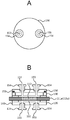
- FIG. A is a top view
- B is a sectional view taken along the line PP in A
- C is a sectional view taken along the line QQ in A.
- FIG. A is a top view
- B is a sectional view taken along the line PP in A
- C is a sectional view taken along the line QQ in A.
- FIG. A is a top view
- B is a sectional view taken along the line PP in A
- C is a sectional view taken along the line QQ in A.
- A is a top view and B is a cross-sectional view taken along the line PP in A.
- FIG. It is a figure explaining the structure of the module 101B for cell cultures concerning 2nd embodiment of this invention.
- A is a top view when the cap 150 is removed, and B is a cross-sectional view.
- 101 C of cell culture modules which concern on 3rd embodiment of this invention.
- A is a top view when the cap 150 is removed, and B is a side view.
- A is a top view when the cap 150 is removed, and B is a cross-sectional view.
- FIG. A is a plan view
- B is a cross-sectional view taken along the line PP in A.
- FIG. It is a figure explaining the connection aspect of the port and syringe by a Luer taper. It is a figure explaining the sealing aspect of a port. It is a figure explaining the structure of the scaffold material 210.
- FIG. A is a plan view
- B is a cross-sectional view taken along line PP in A
- C is a cross-sectional view taken along line QQ in A. It is a figure explaining the procedure of the cell culture method using the module 201A for cell cultures.
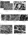
- FIG. 3 shows cytochrome 3A4 (CYP) enzyme activity when Hc cells (top) and hepatoblasts derived from Hc cells were statically cultured using each nanofiber nonwoven fabric (No. 1 to No. 6) as a scaffold.
- CYP cytochrome 3A4
- FIG. 6 shows changes over time in cell density ( ⁇ 107 cells / cm 3) when Hc cells are induced into hepatoblasts using the cell culture apparatus of the present invention and further cultured under reflux.
- 2 shows changes over time in cell density ( ⁇ 107 cells / cm 3) when circulating human frozen hepatocytes using the cell culture apparatus of the present invention. The change with time of dissolved oxygen concentration when circulating human frozen hepatocytes using the cell culture apparatus of the present invention is shown.
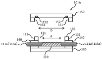
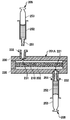
- FIG. 1 shows the configuration of a cell culture module 101A according to the first embodiment of the present invention.
- the cell culture module 101A includes a frame including the substrates 120 and 130 and the mold 140, and a lid 150 (hereinafter referred to as “cap 150”).
- the substrate 130 is provided with an opening 131 to which the cap 150 is attached.
- a screw groove 132 is provided around the peripheral surface (inner peripheral surface) of the opening 131.
- the cap 150 has an outer peripheral surface that is provided with a thread 151 and has the same diameter as the opening 131.
- the cap 150 is attachable to or detachable from the opening 131 (screw cap) by the engagement between the screw thread 151 and the screw groove 132.
- 1A shows a cross-sectional view of the cell culture module 101A when the cap 150 is removed
- FIG. 1B shows a top view of the substrates 120 and 130 and the mold 140 when the cap 150 is removed.
- the cap 150 when attached to the opening 131, constitutes a liquid-tight (or air-tight) internal space 102 (see FIG. 2B described later) together with the substrates 120 and 130 and the mold 140.
- Reference numeral 152 in FIG. 1 indicates a sealing member (for example, an O-ring) for increasing the liquid tightness (or air tightness) of the internal space 102.
- the sealing member 152 is disposed at a contact portion between the cap 150 and the substrate 130, and seals the contact portion when the cap 150 is attached to the opening 131.
- a culture place 110 configured by arranging hollow fiber membranes 111a (113a) and hollow fiber membranes 111b (113b) in a mesh shape is located.
- the hollow fiber membrane 111a (113a) passes through two opposite sides of the mold 140 and is inserted into the mold 140, and is fixed to the mold 140 with potting resin.
- the hollow fiber membrane 111b (113b) passes through the other two opposite sides of the mold 140 and is inserted into the mold 140 to be fixed to the mold 140.
- the configurations of the hollow fiber membranes 111a (113a) and 111b (113b) and the culture site 110 will be described later in detail with reference to FIG.
- the substrates 120 and 130 are not particularly limited as long as the substrates 120 and 130 have a strength suitable for firmly fixing the hollow fiber membranes 111a (113a) and 111b (113b) and the mold 140, for example, acrylic plates.
- Each of the substrates 120 and 130 may be composed of one acrylic plate or the like, or may be composed of two or more acrylic plates or the like.
- the cap 150 may also be an acrylic plate, for example, and may be composed of one or two or more acrylic plates.
- the material of the mold 140 may be any material as long as sufficient adhesiveness with the potting resin is obtained, for example, silicon rubber. Moreover, the potting resin should just have sufficient adhesiveness, for example, various thermosetting resins, such as an epoxy resin, a urethane resin, an unsaturated polyester resin, a silicon resin, a thermoplastic resin, etc. are used.
- various thermosetting resins such as an epoxy resin, a urethane resin, an unsaturated polyester resin, a silicon resin, a thermoplastic resin, etc. are used.
- the opening 131 of the substrate 130 is provided with a size capable of exposing the entire culture field 110 when the cap 150 is removed.
- the opening 131 is sized so that the entire culture field 110 can be located inside thereof.
- the diameter D of the opening 131 is not less than the diameter d of the culture place 110. More specifically, it is preferable that the opening 131 and the culture field 110 are arranged concentrically and that the diameter D of the opening 131 is greater than or equal to the diameter d of the culture field 110. In other words, when viewed from above (see FIG. 1B), the opening area of the opening 131 is preferably equal to or larger than the area of the culture field 110. More specifically, when viewed from the top (see FIG. 1B), the opening 131 and the culture field 110 are preferably arranged so that the entire culture field 110 is located inside the opening 131.
- the entire culture site 110 can be exposed so that it can be visually recognized and operated from the outside. Therefore, in the cell culture module 101A, by removing the cap 150 and exposing the entire culture field 110, a substance can be introduced into an arbitrary position of the culture field 110 or a substance at an arbitrary position can be taken out. However, it is possible without restriction of the size of the substance.
- the cap 150 may have a flow opening 153 for allowing fluid such as a cell suspension to flow from the outside of the module to the internal space 102 or from the internal space 102 to the outside (see FIG. A).
- the flow opening 153 is provided through the cap 150.
- the through-flow port 153 communicates between the outside and the internal space 102 when the cap 150 is attached.
- the flow port 153 is configured by screwing and attaching a port (connection member) 154 to a screw groove formed in the cap 150.
- the figure shows an example in which two through holes 153 are provided in the cap 150, but one or more than three through holes 153 can be provided. Further, the flow port 153 can also be provided in the substrate 120 as shown in FIG. 2B.
- the flow port 153 has a cap 150, substrates 120, 130, and a mold as long as a fluid such as a cell suspension, a culture medium, and a gas can flow from the outside to the inside of the internal space 102 or from the inside to the outside. Any number of frames 140 can be provided at any position.
- the material of the port 154 is not particularly limited, but is usually polycarbonate, polymethyl methacrylate resin (PMMA), cyclic polyolefin, polyethylene, polystyrene, polypropylene, polydimethylsiloxane (PDMS), or the like.
- PMMA polymethyl methacrylate resin
- PDMS polydimethylsiloxane
- the port 154 has a female luer taper, and its inner wall is gradually reduced in diameter in the direction from the outside to the inside of the internal space 102.
- the port 154 is connected to a flow feeding means such as a tube or a syringe having a male luer taper with good liquid tightness.
- Conventionally known standards can be applied to the taper angle and size of the female and male luer tapers.
- the size and shape of the flow-through port 153 are not particularly limited, but are, for example, circular and have a diameter of about 500 ⁇ m to 5 mm.
- the female luer taper of the port 154 only needs to be provided on at least a part of the inner wall of the port 154 so that a flow feeding means having a male luer taper can be inserted.
- the culture field 110 includes a hollow fiber membrane mesh 112 in which hollow fiber membranes 111a and 111b (the hollow fiber membranes 111a and 111b are collectively referred to as a hollow fiber membrane 111) are arranged in a mesh shape, and a scaffold material 115 made of a fiber assembly. And hollow fiber membrane mesh 114 in which hollow fiber membranes 113a and 113b (hollow fiber membranes 113a and 113b are collectively referred to as hollow fiber membrane 113) are arranged in a mesh shape are laminated in this order.
- the membrane base polymer of the hollow fiber membrane 111 forming the hollow fiber membrane mesh 112 may be any material that can be molded on the hollow fiber membrane.
- polyolefins such as polyethylene and polypropylene
- examples include sulfone, polyallyl sulfone, polyether sulfone, polyacrylonitrile, cellulose acetate, polyvinylidene fluoride, and a mixture of two or more of these.
- the outer diameter of the hollow fiber membrane 111 is preferably 50 to 3000 ⁇ m, more preferably 100 to 2000 ⁇ m. If the outer diameter is 50 ⁇ m or more, it is easy to secure a sufficiently large hollow portion in the hollow fiber membrane 111, so that the differential pressure when feeding the culture solution becomes large, and removal of metabolic waste products is insufficient. It is easy to suppress becoming. In addition, when the outer diameter is 3000 ⁇ m or less, the surface area of the hollow fiber membrane 111 per unit volume can be increased, so that it becomes easy to supply sufficient nutrients and gas to the cultured cells.
- the thickness of the hollow fiber membrane 111 is preferably 5 to 500 ⁇ m. If the film thickness is 5 ⁇ m or more, it is easy to prevent the hollow fiber membrane from being destroyed by pressurization during nutrient supply or gas supply. In addition, when the film thickness is 500 ⁇ m or less, the filtration resistance is further reduced, so that the efficiency of nutrient supply and gas supply to the cultured cells and removal of metabolic waste products from the cultured cells is improved.
- the film thickness when the hollow fiber membrane 111 is a multilayer film is the sum of the film thicknesses of the respective layers (film thickness of all layers).
- the inner diameter of the hollow fiber membrane 111 is preferably 10 ⁇ m or more and 2995 ⁇ m or less.
- the hollow fiber membrane 111 a microfiltration membrane, an ultrafiltration membrane, a gas separation membrane or the like can be used. These can be appropriately selected as necessary.
- a hollow fiber membrane having a substance-selective permeability a specific substance can be supplied to cultured cells, or a specific metabolic waste product can be removed from the cultured cells.
- test substances such as specific components, chemical substances, drugs, etc. in the culture medium to the cultured cells, and to discharge waste products and metabolites out of the system and monitor them. .
- hollow fiber membrane having selective substance permeability examples include the above-mentioned microfiltration membrane and ultrafiltration membrane, and further, the hollow fiber membrane having substance selective permeability in the membrane material itself and the selective permeability in the hollow part.
- the gas supply may be performed using a porous hollow fiber membrane.
- a hollow fiber membrane in which a nonporous membrane substrate having a gas separation function is supported by a porous membrane substrate is preferable.
- gas can be supplied into the culture solution without bubble, and thus it is easy to prevent damage to the cultured cells.
- it is easy to prevent a liquid such as a culture solution from entering the hollow portion of the hollow fiber membrane and closing the hollow portion.
- the hollow fiber membrane 111 is preferably subjected to a hydrophilic treatment.
- a hydrophilic treatment By hydrophilizing the hollow fiber membrane, it becomes easy to supply a liquid component such as a culture solution to the cultured cells, and it is also easy to suppress cell adhesion to the surface of the hollow fiber membrane.
- the method for hydrophilizing the hollow fiber membrane include a method of treating the hollow fiber membrane with a hydrophilic polymer such as an ethylene-vinyl alcohol copolymer, glycerin or ethanol.
- hollow fiber membranes can be used for the hollow fiber membrane mesh 112.
- microfiltration membranes that supply nutrients, gas separation membranes that supply gases, hollow fibers with selective permeability to substances that supply specific components to cultured cells or discharge specific metabolic waste products from cultured cells Membranes can be used in any combination.
- the hollow fiber membrane mesh 112 is a plurality of hollow fiber membranes arranged in a mesh shape so that a mesh is formed.
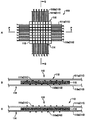
- a form of the hollow fiber membrane mesh 112 for example, a plurality of hollow fiber membranes 111a are arranged in parallel at a predetermined interval to form a sheet, and a plurality of hollow fibers are formed along a direction orthogonal to the hollow fiber membranes 111a.
- a configuration in which the film 111b is arranged in parallel at a predetermined interval to form a sheet can be used (FIG. 3A).
- the number of sheets of the hollow fiber membrane 111 in the hollow fiber membrane mesh 112 is not particularly limited, and preferably 2 to 10 layers. In this example, the sheet has two layers (a layer made of the hollow fiber membrane 111a and a layer made of the hollow fiber membrane 111b).
- hollow fiber membrane mesh 114 and the hollow fiber membrane 113 the same ones as the hollow fiber membrane mesh 112 and the hollow fiber membrane 111 can be used, and preferred forms are also the same.
- the form of the hollow fiber membranes 112 and 114 may be selected according to the supply of nutrients and gas through the hollow fiber membranes 111 and 113 and the removal of metabolic waste products.
- the hollow fiber membranes 111 and 113 are modularized Depends on port design.
- the hollow fiber membrane 111a of the hollow fiber membrane mesh 112 and the hollow fiber membrane 113a of the hollow fiber membrane mesh 114 are preferably the same type of hollow fiber membrane.
- the hollow fiber membrane 111b of the hollow fiber membrane mesh 112 and the hollow fiber membrane 113b of the hollow fiber membrane mesh 114 are preferably the same type of hollow fiber membrane.
- the hollow fiber membranes 111 and 113 are modularized, for example, the hollow fiber membranes 111a and 113a are gathered and connected to one port portion to form a gas supply hollow fiber membrane.
- the hollow fiber membrane 111b and the hollow fiber membrane 113b can be gathered and connected to another port portion to be used as a medium supply hollow fiber membrane.
- an assembly of nanofibers is preferably used as the fiber assembly constituting the scaffold material 115.
- the aggregate of nanofibers is preferably formed by electrospinning (electrospinning) on a substrate.
- the substrate is not particularly limited as long as it can form an assembly of nanofibers on the surface by electrospinning, and examples thereof include aluminum foil.
- the material of the nanofiber is preferably a solvent-soluble polymer from the viewpoint of easy spinning.
- solvent-soluble polymers that can be electrospun include, for example, nylon 4, 6, nylon 6, nylon 6, 6, nylon 12, polyacrylic acid, polyacrylonitrile, polyamide, polycarbonate, polyetherimide, polyethylene oxide, polyethylene Examples include terephthalate, polystyrene, styrene-butadiene copolymer, polysulfone, polyurethane, polyvinyl alcohol, polyvinyl chloride, polyvinyl pyrrolidone, polyvinylidene fluoride, polycaprolactone, polylactic acid, silk, cellulose acetate, chitosan, and collagen.
- the present invention is not limited to these, and a mixture of these polymers, an inorganic material, or a carbon material may be included.
- the molecular weight of the polymer is not particularly limited, but if the molecular weight is too low, the spinnability may be lowered, and if the molecular weight is too high, the viscosity may increase and spinning may be difficult. Even if the polymer is insoluble in a solvent, a thermoplastic polymer can be used when the laser electrospinning method is applied. Examples of the thermoplastic polymer applicable to the laser electrospinning method include polyethylene terephthalate.
- the average diameter (thread diameter) of the nanofiber is preferably 250 nm to 950 nm, more preferably about 300 or about 600 nm, and further preferably about 600 nm. If nanofibers having a thread diameter in this range are used, cells can be cultured for a long time with high activity.
- the obtained cell has a cytochrome P450 (CYP) activity of preferably 2 or more, more preferably 3 or more, and particularly preferably 4 or more.
- CYP cytochrome P450
- the diameter of the single fiber of nanofiber can be measured by the method described in Patent Document 10 above.
- the average diameter of nanofiber single fibers can be measured, for example, as follows.
- the surface of the nanofiber or its aggregate (nanofiber layer) is observed with an electron microscope, the width of the surface of any 20 nanofibers in the obtained electron micrograph is measured, and the average is calculated as the single nanofiber.
- the diameter of the fiber As the electron microscope, a scanning electron microscope (SEM) is preferable.
- the observation magnification is preferably 5000 to 50,000 times. If the observation magnification is 5000 times or more, the diameter of the nanofiber can be easily determined.
- the diameter of the nanofiber single fiber obtained by the image analysis software varies slightly depending on the image quality adjustment for image analysis, the type of the image analysis software, etc., but the difference is within the range of normal experimental error.
- the thickness of the fiber assembly is preferably 0.5 to 100 ⁇ m, more preferably 1 to 50 ⁇ m. If thickness is 0.5 micrometer or more, it will become easy to arrange
- a physiologically active substance By adsorbing or fixing a physiologically active substance to the scaffold material 115, it is possible to control adhesion, proliferation, differentiation, and function expression of cultured cells.
- the physiologically active substance include functional polymers, amino acids, proteins, sugar chains, vitamins and the like.
- a physiologically active substance effective for cell culture for example, a cytokine which is a general term for physiologically active substances having an important role in the growth, differentiation and functional expression of cultured cells. Cytokines include interleukins, blood boosting factors, growth factors and the like. It is also effective to use cell adhesion substrates such as integrins and cadherins involved in cell-extracellular matrix, cell-cell adhesion.
- a cell culture test can be performed by adsorbing or fixing a test substance such as a drug or a chemical substance to the scaffold material 115.
- the culture field 110 has a laminate in which the scaffold material 115 is disposed between the hollow fiber membrane mesh 112 and the hollow fiber membrane mesh 114 described above.
- the scaffold material 115 can be firmly fixed to the hollow fiber membrane meshes 112 and 114, and supply of nutrients and gas to the cultured cells, It is possible to more stably remove metabolic waste products from the cell culture.
- the scaffold material 115 is disposed between the hollow fiber membrane meshes 112 and 114, the distance between the cultured cells adhered to the scaffold material 115 and the hollow fiber membranes 111 and 113 is reduced. Gas supply and removal of metabolic waste products from the cell culture can be performed with higher efficiency, and necrosis of the cultured cells is reduced and the efficiency of the cell culture is improved.
- the size of the culture place 110 may be any size as long as the number of cells necessary for the drug test can be secured, preferably 1 m 2 to 0.1 cm 2, more preferably 600 cm 2 to 0.2 cm 2, and particularly preferably 59 cm 2 to 0.35 cm 2. . Within this range, the uniformity of the scaffold is increased.
- the number of the laminated layers of the hollow fiber membrane meshes 112 and 114 and the scaffold material 115 in the culture site 10 is not particularly limited, and the hollow fiber membrane mesh 114, the scaffold material 115, and the hollow fiber membrane mesh. 112, the scaffold material 115, and the hollow fiber membrane mesh 112 may be laminated in this order, or a larger number of the hollow fiber membrane meshes 112 and 114 and the scaffold material 115 may be laminated.
- a tube or the like is connected to the above-described port 154, so that the hollow fiber membranes 112 and 114 of the hollow fiber membrane meshes 112 and 114 can be used as a route for supplying nutrients and gases and removing metabolic waste products.
- a third path other than 111 and 113 can be provided. Therefore, compared with the case of supplying nutrients and gas using only the hollow fiber membrane or removing metabolic waste products, cell culture under more conditions and independently controlling those conditions, It can be performed more simply.
- the cap 150 may be attached to and detached from the opening 131 by providing a screw groove 132 on the outer peripheral surface of the opening 131 of the substrate 130 and providing a screw thread 151 on the inner peripheral surface of the cap 150.
- FIG. 4A shows a cross-sectional view of the cell culture module 101A when the cap 150 is removed.
- the screw thread 151 and the screw groove 132 do not come into contact with the medium or the like introduced into the internal space 102. For this reason, it is possible to prevent the screw thread 151 and the screw groove 132 from adhering to each other due to a dried medium or the like, and to enhance the detachability of the cap 150.
- the culture field 110 is configured by arranging the scaffold material 115 between the hollow fiber membrane mesh 112 and the hollow fiber membrane mesh 114 has been described.
- the culture field 110 may be configured by laminating a hollow fiber membrane mesh 114, a hollow fiber membrane mesh 112, and a scaffold material 115 in this order.
- the scaffold material 115 can be arrange
- (1) Cell introduction procedure First, cells are introduced into the culture site 110.
- the introduction of cells can be performed with the cap 150 removed (see FIG. 1). When the cap 150 is removed, the entire culture field 110 is exposed through the opening 131. For this reason, it is possible to introduce a cell into an arbitrary position on the culture field 110 while visually checking the entire culture field 110.
- the introduction of cells is performed, for example, by inserting a pipette or the like into the internal space 102 from the opening 231 and dropping the cell suspension at an arbitrary position on the culture field 110.
- a substance such as a test substance may be introduced together with the cell suspension. For example, by inserting tweezers or the like into the culture space 102 and placing the solid substance on the culture place 110, the substance can be introduced at an arbitrary position without restriction on the size of the substance.
- the cell introduction may be performed by connecting a cell suspension liquid feeding means to the port 154.
- a flow of the cell suspension is formed in the internal space 102, and the cells are transported by the flow and dispersed on the culture site 110.
- a substance such as a test substance may be introduced together with the cell suspension.
- the substance needs to be introduced as a solution or a dispersion, and the substance can be introduced only at an arbitrary position on the culture place 110. It is difficult to introduce to.
- the hollow fiber membrane 111a and the hollow fiber membrane 113a are gathered and connected to one port portion to supply gas, and the hollow fiber membrane 111b and the hollow fiber membrane 113b are gathered.
- Cell culture is performed by supplying a medium connected to another port.
- the cell culture uses, for example, a hollow fiber membrane that is a gas separation membrane as the hollow fiber membranes 111a and 113a, and a hollow fiber membrane having substance-selective permeability as the hollow fiber membranes 111b and 113b, and the hollow fiber membrane 111a, While supplying a gas containing oxygen from one end of 113a, the gas is discharged from the other end. Further, nutrients of the cultured cells are supplied from one end of the hollow fiber membranes 111b and 113b, and waste products and metabolites of the cultured cells are discharged from the other end. Thereby, it is also possible to analyze the discharged components online and to evaluate the growth status of the cultured cells continuously while culturing the cultured cells.
- a test substance is administered to cultured cells from one end of the hollow fiber membranes 111b and 113b, and a solution containing waste products and metabolites is discharged from the other end of the hollow fiber membranes 111b and 113b, and this solution is analyzed.
- a solution containing waste products and metabolites is discharged from the other end of the hollow fiber membranes 111b and 113b, and this solution is analyzed.
- the cultured cells can be recovered by removing the cap 150 again.
- the entire culture field 110 is exposed through the opening 131. For this reason, it is possible to selectively collect cells at an arbitrary position on the culture field 110 while visually checking the entire culture field 110.
- the cells are collected by inserting a pipette into the culture space 102 through the opening 131 and sucking the cells at an arbitrary position on the culture field 110.
- a spatula can be inserted into the culture space 102, and cells at an arbitrary position on the culture field 110 can be scraped and collected.
- the cells may be collected by taking out the scaffold material 115 to which the cells are attached as it is.
- the substance when a substance such as a test substance is introduced into the culture place 110, the substance can be collected together with the cells. For example, by selectively taking out a solid substance at an arbitrary position on the culture site 110 with tweezers or the like, it can be recovered from an arbitrary position without any restriction on the size of the substance.
- FIG. 6 shows the configuration of a cell culture module 101B according to the second embodiment of the present invention.
- the configuration in which the cap 150 is attached to and detached from the opening 131 by engaging the screw groove 132 of the opening 131 and the thread 151 of the cap 150 has been described.
- the cell culture module 101B according to this embodiment is different from the cell culture module 101A in that the cap 150 is attached to and detached from the opening 131 by screws 161 and screw holes 162.
- the screw hole 162 is provided through the cap 150, the substrate 130, the mold 140, and the substrate 120.
- the screw holes 162 are provided at positions that do not interfere with the opening 131 and the internal space 102, the hollow fiber membrane 111a (113a), and the hollow fiber membrane 111b (113b) (preferably at the four corners of the cell culture module 1B as shown in the figure). It has been.
- the cap 150 is attached to the opening 131 by superimposing the cap 150, the substrate 130, the mold 140, and the substrate 120 so that the positions of the screw holes 162 formed in each of the caps 150, and the screws 161 are inserted into the screw holes 162. Do by screwing.
- the cell culture module 101B is easy to process, and there is no problem of sticking between the thread 51 and the screw groove 132 due to drying of the medium that can occur in the cell culture module 101A.
- the screw hole 162 needs to penetrate through the cap 150 to at least a part of the substrate 130 in order to attach the cap 150 to the opening 131.
- the screw holes 162 are formed in the entire board 130, and further up to the mold 140 and the board 120. Further, the number and positions of the screw holes 162 are not limited to the form shown in the drawing, and can be appropriately changed.
- FIG. 7 shows a configuration of a cell culture module 101C according to the third embodiment of the present invention.
- the cell culture module 101 ⁇ / b> C is configured such that the cap 150 is attached to and detached from the opening 131 by engagement between an engagement hole 133 provided in the substrate 130 and an engagement claw 155 provided in the cap 150. This is different from the cell culture module 101A according to the first embodiment described above.
- the engagement hole 133 is provided at the peripheral edge of the opening 131 of the substrate 130. Further, the engagement claw 155 is provided at a position that can correspond to the position of the engagement hole 133 when the cap 150 is closed in the opening 131.
- the engagement hole 133 and the engagement claw 155 need only have shapes that can be engaged. For example, as shown in the figure, after the engagement claw 155 is inserted into the engagement hole 133, the cap 150 is rotated. In general, a structure in which the engagement claw 155 is engaged with the engagement hole 133 can be adopted.
- FIG. 8 shows a configuration of a cell culture module 101D according to the fourth embodiment of the present invention.
- the cell culture module 101D is different from the cell culture module 101A according to the first embodiment described above in that the cap 150 is attached to and detached from the opening 131 by a fastener 163.
- the fastener 163 may be, for example, one that sandwiches and holds the cap 150 with the opening 131 closed and the substrate 120.
- a recess (see reference numeral 164 in the figure) for fitting the fastener 163 may be provided on the upper surface of the cap 150 and the lower surface of the substrate 120.
- the cell culture modules 101C and 101D are excellent in the detachability operability of the cap 150. Further, in the cell culture modules 101C and 101D, there is no problem of fixation between the screw thread 151 and the screw groove 132 due to drying of the medium that can occur in the cell culture module 101A.
- the cap 150 when the cap 150 is removed, the entire culture place 110 can be exposed so that it can be visually recognized and operated from the outside. For this reason, in the cell culture module according to the present invention, the cap 150 is removed to expose the entire culture field 110, whereby a substance can be introduced into an arbitrary position of the culture field 110, or a substance at an arbitrary position can be externally provided. It can be taken out without any restriction on the size of the substance. It is also possible to perform measurement by inserting a probe for pH measurement, dissolved oxygen concentration measurement and the like in the internal space 102.
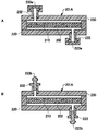
- FIG. 8 shows a configuration of a cell culture module 201A according to the fifth embodiment of the present invention.
- a substrate 220, 230 and a mold 240 constitute a liquid-tight (or air-tight) culture space (culture region) 202.
- a scaffold material 210 made of a hollow fiber membrane and a fiber assembly is disposed in the culture space 202.
- the scaffold material 210 is fixed to the mold 240 with a potting resin, and the substrates 220 and 230 form a culture space 202 by sandwiching them.
- the substrates 220 and 230 may be any material as long as they have a strength suitable for being firmly fixed with the scaffold material 210 and the mold 240 interposed therebetween, and are, for example, acrylic plates.
- each of the substrates 220 and 230 may be composed of one acrylic plate or the like, or may be composed of two or more acrylic plates or the like. Further, when a plurality of culture spaces 202 are provided in the cell culture module 201A, there may be two or more substrates 220 and 230 forming these.
- the material of the mold 240 may be any material as long as sufficient adhesiveness with the potting resin is obtained, for example, silicon rubber. Moreover, the potting resin should just have sufficient adhesiveness, for example, various thermosetting resins, such as an epoxy resin, a urethane resin, an unsaturated polyester resin, a silicon resin, a thermoplastic resin, etc. are used.
- various thermosetting resins such as an epoxy resin, a urethane resin, an unsaturated polyester resin, a silicon resin, a thermoplastic resin, etc. are used.
- a screw hole 221 is formed in the substrate 220.
- the screw hole 221 penetrates the substrate layer 220 and communicates the outside and the inside culture space 202 of the cell culture module 201A.
- a part of the screw hole 221 is threaded, and a port (connecting member) 222 is screwed in and attached.
- the screw hole 221 and the port 222 constitute a flow opening for allowing a fluid such as a cell suspension, a culture medium, and a gas to flow from the outside to the inside of the culture space 202 or from the inside to the outside.
- the screw holes 221 and the ports 222, and the flow holes formed from these are arranged on the substrate 220 at positions corresponding to the scaffold material 210 (specifically, a fiber assembly 215 to be described later).
- the two flow openings are disposed at positions that are symmetrical (point-symmetric) with respect to the center of the scaffold material 210 (specifically, a fiber assembly 215 described later).
- the material of the port 222 is not particularly limited, but is usually polycarbonate, polymethyl methacrylate resin (PMMA), cyclic polyolefin, polyethylene, polystyrene, polypropylene, polydimethylsiloxane (PDMS), or the like.
- PMMA polymethyl methacrylate resin
- PDMS polydimethylsiloxane
- As the port 222 a so-called syringe port widely used in the medical field can be suitably used.
- the board 230 is provided with a screw hole 231, and a port 232 is attached to the screw hole 231.
- the configuration of the screw hole 231 and the port 232 is the same as that of the screw hole 221 and the port 222.
- the port 222 and the port 232 have a female luer taper, and the inner wall thereof is gradually reduced in diameter in the direction from the outside to the inside of the culture space 202.
- the port 222 and the port 232 are connected to a flow feeding means such as a tube or a syringe having a male luer taper with good liquid tightness.
- Conventionally known standards can be applied to the taper angle and size of the female and male luer tapers.
- the size and shape of the screw holes 221 and 231 and the ports 222 and 232 are not particularly limited, but are, for example, circular and have a diameter of about 500 ⁇ m to 5 mm.
- the female-type luer taper of the port 222 and the port 232 is only required to be provided so that a flow-feeding means having a male-type luer taper can be inserted into at least a part of their inner walls.
- the screw holes 221 and 231 may be perforations as long as they communicate between the outside of the cell culture module 201A and the culture space 202 and can be attached to the ports 222 and 232.
- FIG. 9 shows a connection mode with a port using a syringe as an example of liquid feeding means.
- the fluid held in the syringe body 252 here, cell suspension is taken as an example
- the plunger 253 into the syringe body 252. Can be discharged to the outside.
- a disposable syringe generally used in the medical field can be suitably used as the syringe 205.
- the distal end portion 251 of the syringe 205 is provided with a male luer taper that decreases in diameter from the connection portion with the port 222 and / or the syringe body 252 of the cell culture module 201A toward the opening.
- the male luer taper of the distal end 251 of the syringe 205 and the female luer taper of the port 222 and / or the port 232 of the cell culture module 201A have substantially the same shape and can be fitted. Therefore, the syringe 205 and the cell culture module 201 ⁇ / b> A can be easily and fluid-tightly connected by inserting the distal end portion 251 into the port 222 and / or the port 232. Thereby, in the cell culture module 201A, the cell suspension in the syringe 205 can be introduced into the culture space 202 without causing leakage.
- FIG. 10 shows a luer plug (sealing member) (see FIG. 10).
- FIG. 13A shows luer plugs 223a and 233a that can be detachably attached to the port 222 and the port 232.
- FIG. 10B shows luer plugs 223b and 233b having male luer tapers that can be fitted to the female luer tapers of the port 222 and the port 232.
- the port 222 and / or the port 232 from which the syringe 205 has been removed can be easily sealed.
- the luer plug can be attached to the port 222 and the port 232 of the unused cell culture module 201A.
- the cell culture module 201A in use can be attached to the port 222 and the port 232 when it is not necessary to attach the syringe 205 or the like.
- the syringe 205 is described as an example of the flow feeding means connected to the port 222 and the port 232, but a similar connection using a Luer taper feeds various fluids including a liquid such as a medium and a gas such as oxygen. It can carry out between various flow-feeding means, such as a tube, a pump, and a stopcock.
- various flow-feeding means such as a tube, a pump, and a stopcock.
- the cell culture module 201A can easily introduce a fluid such as a cell suspension, a culture medium, or gas without sealing the connection portion using a curable resin or the like (or Discharge).
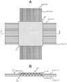
- the scaffold material 210 includes a hollow fiber membrane mesh 212 in which hollow fiber membranes 211a and 211b (211) are arranged in a mesh shape, a fiber assembly 215, and a hollow fiber membrane 213a and 213b (213) in a mesh shape.
- the hollow fiber membrane mesh 214 is laminated in this order.
- the hollow fiber membrane mesh 212 is formed by arranging a plurality of hollow fiber membranes in a mesh shape so that a mesh is formed.
- a plurality of hollow fiber membranes 211a (hollow fiber membranes 211) are arranged in parallel at a predetermined interval to form a sheet, and in a direction perpendicular to the hollow fiber membranes 211a.
- a plurality of hollow fiber membranes 211b (hollow fiber membranes 211) are arranged in parallel at a predetermined interval to form a sheet shape, thereby forming a mesh shape (FIG. 11A).
- the number of sheets of the hollow fiber membrane 211 in the hollow fiber membrane mesh 212 is not particularly limited, and preferably 2 to 10 layers. In this example, the sheet has two layers (a layer made of the hollow fiber membrane 211a and a layer made of the hollow fiber membrane 211b).
- the hollow fiber membrane mesh 214 and the hollow fiber membrane 213 can be the same as the hollow fiber membrane mesh 212 and the hollow fiber membrane 211, and the preferred forms are also the same.
- the form of the hollow fiber membrane meshes 212 and 214 may be selected according to the supply of nutrients and gas through the hollow fiber membranes and the removal of metabolic wastes, and also for the design of the port part when modularizing the scaffold material 210 Dependent.
- the hollow fiber membrane 211a of the hollow fiber membrane mesh 212 and the hollow fiber membrane 213a of the hollow fiber membrane mesh 214 are preferably the same type of hollow fiber membrane.
- the hollow fiber membrane 211b of the hollow fiber membrane mesh 212 and the hollow fiber membrane 213b of the hollow fiber membrane mesh 214 are preferably the same type of hollow fiber membrane.
- the hollow fiber membrane 211a and the hollow fiber membrane 213a are gathered and connected to one port portion to form a gas supply hollow fiber membrane.
- the membrane 211b and the hollow fiber membrane 213b can be gathered and connected to another port portion to be used as a medium supply hollow fiber membrane.
- the scaffold material 210 has a laminate in which a fiber assembly 215 is disposed between the hollow fiber membrane mesh 212 and the hollow fiber membrane mesh 214 described above. As described above, by arranging the nanofiber layer between the hollow fiber membrane meshes, the nanofibers can be firmly fixed to the hollow fiber membrane meshes, supplying nutrients and gases to the cultured cells, Removal of metabolic waste products can be performed more stably.
- a tube or the like is connected to the ports 222 and 232 described above, so that the hollow fiber membrane meshes 212 and 214 can be used as a route for supplying nutrients and gases and removing metabolic waste products.
- a third path other than the thread films 211 and 213 can be provided. Therefore, compared with the case of supplying nutrients and gas using only the hollow fiber membrane or removing metabolic waste products, cell culture under more conditions and independently controlling those conditions, It can be performed more simply.
- the number of flow ports may be one, and in this case, it may be disposed on either the substrate 220 or the substrate 230.
- the module for cell culture according to the present invention three or more flow ports may be provided. In this case, one or more may be provided on the substrate 220 and the substrate 230, respectively.
- the flow port may be configured to have a female luer taper and be capable of being liquid-tightly connected to a flow feeding means having a corresponding male luer taper.
- a form in which the holes perforated in the substrates 220 and 230 have a female-type luer taper can be cited.
- the number of layers of the hollow fiber membrane mesh and the fiber assembly of the scaffold material 210 is not particularly limited, and the hollow fiber membrane mesh, nanofiber layer, hollow fiber membrane mesh, nanofiber layer
- the cell culture scaffold material in which the hollow fiber membrane meshes are laminated in this order may be used, or a cell culture scaffold material in which more than this is laminated may be used.
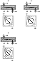
- a cell suspension feeding means is connected to the ports 222 and 232 of the cell culture module 201A.
- the syringe syringe 205
- the liquid feeding means may be a tube or a pump.
- connection between the ports 222 and 232 and the syringe can be made liquid-tight by inserting the male luer taper at the tip of the syringe into the female luer taper of the ports 222 and 232.
- a flow of cell suspension is formed in the culture space 202 from the port 232 side to the port 222 side (see arrow in FIG. 12A).
- the ports 222 and 232 are disposed on the substrates 220 and 230 at positions corresponding to the scaffold material 210 (specifically, the fiber aggregate 215). For this reason, the cells introduced into the culture space 202 are transported in the flow and dispersed on the fiber assembly 215.
- the ports 222 and 232 are disposed at positions that are symmetric (point symmetric) with respect to the center of the scaffold material 210 (specifically, the fiber assembly 215). For this reason, the flow of the cell suspension from the port 132 side to the port 222 side can be effectively generated in the entire culture space 202, and the cells are efficiently dispersed on the fiber assembly 215 by the flow. It is possible.
- a flow of cell suspension is formed in the culture space 202 from the port 222 side to the port 232 side (see the arrow in FIG. 12B), introduced into the culture space 202, and dispersed on the fiber assembly 215.
- the cells are further uniformly dispersed on the fiber assembly 215 by being conveyed in the flow.
- step 2 and step 3 can be appropriately set depending on conditions such as the type of cell, the amount (concentration) in the suspension, and the target culture density.
- the procedure 4 is not essential, and depending on the above conditions, the cells may be sufficiently uniformly dispersed on the fiber assembly 215 even in the procedures 2 and 3 (without the procedure 4).
- cell culture uses, for example, a hollow fiber membrane that is a gas separation membrane as the hollow fiber membranes 211a and 213a, and a hollow fiber membrane having substance-selective permeability as the hollow fiber membranes 211b and 213b. While supplying a gas containing oxygen from one end of 213a, the gas is discharged from the other end. Further, nutrients of the cultured cells are supplied from one end of the hollow fiber membranes 211b and 213b, and waste products and metabolites of the cultured cells are discharged from the other end. Thereby, it is also possible to analyze the discharged components online and to evaluate the growth status of the cultured cells continuously while culturing the cultured cells.
- a test substance is administered to cultured cells from one end of the hollow fiber membranes 211b and 213b, and a solution containing waste products and metabolites is discharged from the other end of the hollow fiber membranes 211b and 213b, and this solution is analyzed.
- a solution containing waste products and metabolites is discharged from the other end of the hollow fiber membranes 211b and 213b, and this solution is analyzed.
- one or two or more flow ports are made into one group, the flow ports are divided into two groups, a cell suspension is introduced from one flow port group A, and discharged from the other flow port group B.
- the flow port group A and the flow port group B are symmetrical (point-symmetric) with respect to the center of the scaffold material 210 (specifically, the fiber assembly 215).
- FIG. 13 shows the configuration of a cell culture module 201B according to the sixth embodiment of the present invention.
- the cell culture module 201B is different from the cell culture module 201A according to the fifth embodiment in that a screw hole 221 and a port 222, and a through-flow port constituted by these are arranged in the substrate 230. . That is, in the cell culture module 201A, two flow ports are provided on different substrates 220 and 220 (see FIG. 8), whereas in the cell culture module 201B, the two flow ports are the same. It is provided on the substrate 230. Also in the cell culture module 201B, the two flow openings are arranged at positions that are symmetric (in this embodiment, line symmetric) with respect to the center of the scaffold material 210 (specifically, a fiber assembly 215 described later). It is installed.
- the configuration of the cell culture module 201B other than the configuration of the above-described flow outlet is the same as that of the cell culture module 201A.
- two flow holes are provided on the substrate 230.
- three or more through holes may be provided.
- the through holes may be provided on either the substrate 220 or the substrate 230.
- FIG. 12 shows the cell introduction procedure of the cell culture method using the cell culture module 201B. Also in the cell culture module 201B, the flow from the port 232 side to the port 222 side and the flow in the opposite direction are alternately generated according to the above-described procedures 1 to 5, so that the cells can be uniformly distributed on the fiber assembly 215. It can be dispersed and introduced with a highly uniform concentration distribution. As a result, it is possible to perform culture without causing a decrease in cell growth rate or causing degeneration / necrosis.
- any two flow ports are selected, and the cell suspension is flowed through one of the flow channels.
- the flow of the cell suspension as described in FIG. 12 may be generated by introducing from the mouth and discharging from the other flow port.
- one or two or more flow ports are made into one group, the flow ports are divided into two groups, a cell suspension is introduced from one flow port group A, and discharged from the other flow port group B.
- a flow of the cell suspension as described in FIG. This point is as described in the section of the cell culture method in the cell culture module according to the fifth embodiment.
- the module for cell culture according to the seventh embodiment provides a module for cell culture comprising a culture field in which a hollow fiber membrane and a fiber assembly composed of nanofibers having an average diameter of 250 nm to 950 nm are arranged.
- the average diameter of the nanofiber is preferably about 300 nm or about 600 nm, more preferably about 600 nm.
- the hollow fiber membranes are preferably arranged in a mesh shape, and a nanofiber layer composed of an assembly of nanofibers is in contact with the two on the outer surface of the hollow fiber membrane and / or between the hollow fiber membranes (flat plate). ) Are arranged in a liquid-tight manner.
- a cell inlet for injecting cultured cells and an opening other than the cell inlet are formed at positions corresponding to the nanofiber layer of the cover. The opening is used for supplying nutrients and air by connecting a tube, removing metabolic waste, or observing the culture state by connecting a microscope.
- the cell inlet and the opening are sealed by a sheet that can be connected to a microscope, a tube, etc., and can be inserted with an injection needle, if necessary.
- a tube or the like can be connected to the opening as a route for supplying nutrients and gas and removing metabolic waste products.
- cell culture can be performed more easily under more conditions and independently controlling those conditions.
- the module has a hollow fiber membrane mesh with both ends of the hollow fiber membrane gathered, the opening is connected to the port part, and waste products and metabolites etc. discharged from the hollow fiber membrane are introduced to an external device. Analyzing with is possible.
- a test substance is administered to cultured cells cultured in the module from one end of the hollow fiber membrane, and a solution containing waste products and metabolites is discharged from the other end of the hollow fiber membrane, and this solution is analyzed and monitored.
- administration of the test substance and discharge of the solution containing waste products and metabolites may be performed by a tube connected to the opening.
- the cell culturing module of the present invention described above has a cell culture scaffolding material placed between two covers and sealed in a liquid-tight manner, thereby dividing the culture region into a fixed region. Condition control is easy.
- the module can be made more compact than a module in which the cell culture scaffold material is immersed in the culture solution in the container. Therefore, even when multiple samples are arranged side by side, multiple samples and multiple conditions can be cultured simultaneously. The culture space can be further reduced.
- the cover of the module for cell culture of the present invention has a cell inlet and an opening other than the cell inlet, and the cell inlet and the opening are closed with a sheet. Therefore, a new path other than the hollow fiber membrane of the hollow fiber membrane mesh can be provided by connecting a tube or the like to the opening of the cover.
- This increases the number of pathways to cultured cells, so it is possible to increase the conditions for supplying nutrients and gases and removing metabolic waste products with a simpler method, and to perform cell culture with independent control of those conditions. it can.
- the cell injection port for injecting cultured cells is provided independently, even when a tube or a microscope is connected to the opening after the module is manufactured, the cultured cells can be easily added to the cell culture scaffold material in the module. Can be injected and glued.
- the cell culture module of the present invention is a cell having a nanofiber layer. Since the culture scaffold material is provided, the cultured cells can enter the nanofiber layer and adhere and proliferate three-dimensionally. Therefore, the cultured cell form is close to that in the living body, and a cultured cell with higher reliability of evaluation can be obtained in drug efficacy tests, toxicity tests, safety tests, etc. of substances such as pharmaceuticals, chemical substances and cosmetics.
- Preferred configurations of the cell culture module according to the seventh embodiment of the present invention include, for example, JP 2009-100, JP 2010-148496, JP 2010-148497, and 2011-239756. It is described in the publication.
- the present invention also provides a (circulating) cell culture device including the cell culture module of the present invention.
- the apparatus for cell culture of the present invention includes a cell culture module, oxygen supply means, and medium supply means. Moreover, a monitoring means, an analysis means, a sampling means, etc. may be included as needed.
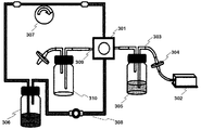
- FIG. 16 An example of the apparatus for cell culture of the present invention is shown in FIG. 16 (hereinafter, the numbers in parentheses correspond to the numbers in FIG. 16).
- the oxygen supply means is means for supplying oxygen to the cells through the hollow fiber membrane, and includes, for example, an air pump 302 for sending out oxygen, a tube 303 constituting an oxygen supply circuit to the module 301, A filter 304 for preventing fine dust (for example, a diameter of 0.22 ⁇ m) from entering the hollow fiber membrane, a moisturizing water storage tank 305, and the like can be included.
- the medium supply means includes, for example, a storage tank (medium bottle 306) for the medium to be supplied, a medium supply for supplying the medium to the cells through the hollow fiber membrane and circulating while removing metabolic waste products.
- a (circulation) pump 307 and a tube 308 as a medium supply (circulation) circuit are included.
- sampling means is means for appropriately collecting a medium from the cell culture module 301 and includes a sampling port 309 connected to the cell culture module 301, a storage tank for the collected medium, and the like 310.
- the cell culture module of the present invention is a means for monitoring the sampled medium and circulating medium components, test substances, metabolite concentrations, etc. over time (monitoring means)
- Means for analyzing (analyzing means) may be included.
- the cell culture module of the present invention can cultivate cells for a long period of time while preventing their dedifferentiation and maintaining their functions.
- the cells used in the cell culture module of the present invention are not particularly limited, but include adherent animal cells such as human fetal foreskin fibroblasts, Chinese hamster lung fibroblasts, chicken fetal fibroblasts, and Syrian hamster neonatal kidney cells. Examples include fibroblasts, human cervical cancer cells, Chinese hamster ovary cells, mouse breast cancer cells, epithelial cells such as African green monkey kidney cells, and vascular endothelial cells.
- culture of primary cells such as hepatocytes, coronary artery endothelial cells, Golden Hamter Langerhans cell group, rat thymic epithelial cells, rat renal epithelial cells, etc., which are difficult to culture while maintaining the function of the cells It is suitable for.
- the cell culture module of the present invention is also applicable to frozen cells.
- Frozen cells generally have a slow growth rate and are difficult to maintain for a long time.
- the function of hepatocytes is greatly reduced within a few days. According to the cell culture method of the present invention, it is possible to perform culture for a long time while maintaining a high function.
- the medium used for culturing is determined according to the type of cultured cells, and may be any medium that is usually used as a medium for the cells.
- the culture method of the present invention can also be used for serum-free culture.
- Example 1 Cell Culture Using Cell Culture Scaffold Material Consisting of Nanofiber Layer Fabrication and analysis of nonwoven fabric 1.1 Fabrication of nanofiber layer Add 10% to 15% polyacrylonitrile powder by weight to dimethylacetamide (Wako Pure Chemical Industries) heated in a constant temperature water bath at 80 ° C and stir well to complete And was allowed to stand at room temperature to prepare a stable polyacrylonitrile dope. Furthermore, the dope was filled in a disposable syringe (Terumo 20 ml, SS-20ESz), a nozzle (18G ⁇ 11/2) was mounted, and the dope was installed in an electrocross pinning apparatus (Katek).
- a disposable syringe Teumo 20 ml, SS-20ESz
- a nozzle (18G ⁇ 11/2) was mounted, and the dope was installed in an electrocross pinning apparatus (Katek).
- silver paper is stuck around the target (roll).
- the voltage is 12kV
- the plunger push-out speed of the syringe is 0.03mm / min
- the distance to the target (roll) is 200mm
- the target rotation speed is 1m / min
- the left and right reciprocating movement (traverse) speed is 10cm / min
- the spinning time is 120min.
- a nanofiber layer nonwoven fabric
- Cell culture experiment 2.1 Materials and equipment used [equipment used]
- (1) Cell culture module The cell culture module was produced according to a report (Japanese Patent Laid-Open No. 2011-239756).
- a hollow fiber membrane for oxygen supply and a hollow fiber membrane for nutrient supply of the medium are arranged inside the module, and a nanofiber nonwoven fabric sheet for cell attachment is charged and sealed between the hollow fiber membranes.
- Cells adhering to the non-woven fabric can be proliferated by always being supplied with abundant nutrients and oxygen from a large amount of medium in the medium bottle and the air pump in a three-dimensional culture state.
- FIG. 16 (2) Cell culture device A circulating cell culture device (FIG. 16) having the following configuration was used. ⁇ One tube pump (perista pump) for medium circulation Flow rate 8mL / hr, 60mL / hr ⁇ 1 pump for air supply Flow rate 1.2L / hr, 3L / hr (Pump is filter (ADVANTEC, pore size 0.2 ⁇ m), so that suction gas of 0.2 ⁇ m or more will not enter the hollow fiber membrane. Yes.) ⁇ 3 bottles (medium bottle, air disposal empty bottle, intake air moisturizing water bottle) ⁇ Air line and culture medium circulation line (both are silicon tubes) ⁇ Sampling port (port for collecting medium) ⁇ Tube joint (resin) ⁇ Plate for placing the device
- CO2 incubator Direct incubator (Thermo) ⁇ Air pump: CHIKARA N ⁇ 1500 (NISSO) ⁇ Medium pump: Low flow rate SJ-1211L type (TOTO) ⁇ SEM: KEYENCE
- [cell] -Hc cells normal human fetal liver cells (purchased from DS Pharma Biomedical) ⁇ Frozen human hepatocytes: Adult hepatocytes sold by BIOPREDIC International, France (Purchased Human Cryopreserved Hepatocytes, Bach: HEP187082 from domestic CA Corporation)
- Hc cell culture medium GIBCO D-MEM / F-12 ⁇ 11330032 Add 500% Fetal Bovine Serum, Hyclone ⁇ 10437028/10% of the required medium volume, and Nacalai Tesque ⁇ Sodium bicarbonate and injection Penicillin G potassium (manufactured by Meiji Seika Co., Ltd.), streptomycin sulfate (Meiji Seika Co., Ltd.), and Human-acidic FGF (Cosmo Bio) were used.
- -Cryopreservation medium Cryopreservation solution for normal cells-R-055-50 (Kurabo) ⁇
- Adult hepatocyte culture medium Incubation medium (BIOPREDIC) Long-term culture medium (BIOPREDIC) Thawing medium (BIOPREDIC) Celling medium (Seeding medium) (BIOPREDIC)
- Nanofiber nonwoven fabrics having various thread diameters (average diameters) were prepared according to the method of 1.1. The thawed cells were seeded on each non-woven fabric, and the functional expression of the cells was analyzed by the following method.
- the petri dish (35 mm in diameter) was laid with a non-woven fabric for scaffolding on the bottom and fixed to the bottom with a 2 mm diameter silicon tube.
- 9 mL of a medium preliminarily warmed to 37 ° C. was dispensed into a 15 mL centrifuge tube, the cell-containing tube was taken out of the freezer, and warmed in a constant temperature water bath. It was removed after warming for about 0.5 minutes, and thawed thoroughly with a pipette. Further, after centrifugation with a swing centrifuge (1000 G), the supernatant was removed, and the cells precipitated with a pipette were suspended in the medium. The cells were stained with trypan blue, the number of cells was counted with a hemocytometer under a phase contrast microscope, and the cell density in the suspension medium was estimated.
- the cells were diluted with a medium to a density suitable for culture (104 cells to 105 cells / 2 mL), and seeded with 2 mL of the medium suspension added to a petri dish with a nonwoven fabric fixed to the bottom.
- the lid was covered, and the medium was gently shaken several times back and forth and left and right to shake the medium on the non-woven fabric on the bottom of the petri dish so that the cells were evenly dispersed.
- the culture was started after standing in a CO2 incubator. After 5 to 12 hours, the medium was changed, cells that did not adhere to the bottom surface were removed together with the medium, and left in a CO2 incubator.
- the medium was changed between 2 and 3 days. On the 7th day of culture, the medium was replaced with a medium supplemented with 1 mM sodium butyrate. On the 8th day, 1 mM dairy sodium and cytochrome 3A4 (CYP3A4) enzyme inducer On the 14th day, the medium was changed to a medium supplemented with 10 ⁇ M rifampsin and the substrate benzyloxylysorphine was added and reacted at 37 ° C. for 30 minutes. The reaction solution was treated with ⁇ -glucuronidase and arylsulfatase acetate buffer solution, and precipitated.
- CYP3A4 cytochrome 3A4
- the function of the cultured cells was measured using the value obtained by quantifying the product resorufin dissolved in ethanol by fluorescence measurement (excitation 550 nm fluorescence 600 nm) as the enzyme activity.
- fluorescence measurement excitation 550 nm fluorescence 600 nm
- concentration a calibration curve prepared with ethanol in which resorufin was dissolved was used.
- Hc cells 105 cells
- a nonwoven fabric was spread on the bottom of a 35 mm diameter petri dish
- Hc cells were seeded on 105 cells / pet.
- 2 mL of medium for Hc cells was added, the medium was changed for 5 hr immediately after seeding to remove cells that did not adhere and floated, and the medium was changed every day after 3 days, 5 days, and 7 days of culture.
- the number of cells was analyzed and compared to the concentration at which glucose in the supplemented medium decreased around the elapsed days.
- Hc cells were proliferated and cultured in reflux cultures, and were subjected to long-term maintenance culture as liver parenchymal cells by induction and maturation, and the cell functions were measured. .
- Cell preparation Hc cells (fetal human hepatocytes) were thawed and seeded in a petri dish, and it was confirmed that the cells were proliferating in the petri dish.
- Ethanol water was circulated in the medium line to sterilize the inside of the module, the ethanol water was discarded, and the water was circulated in the medium line to completely remove the ethanol water. Water was discarded and the medium was circulated in the medium line to confirm stable operation.
- Circulating cell culture The apparatus was installed in a CO2 incubator and circulated with a medium to confirm the stable operation of the apparatus.
- the medium volume in the medium bottle was started at 40 mL.
- the culture medium was sampled from the sampling port, the glucose concentration was analyzed, the number of cells in the module was estimated from the glucose consumption rate, and the changes over time were traced. Similarly, the increase in ammonia, which is an inhibitor of cell growth, was traced in the same manner, and the medium was changed when it did not exceed 2 mM.
- the medium was changed regardless of the glucose concentration when consumption of glucose of 50 mg / dL or more was not observed by the first 9 days.
- the medium was replaced with fresh medium when the glucose concentration of the medium fell below 250 mg / dL and when the consumption rate of glucose was 50 mg / dL or more per day.
- the amount of medium in the medium bottle was increased as necessary in accordance with the frequency of medium exchange.
- the function of the cells was quantitatively evaluated from the relationship between the given substrate and reaction rate by inducing cytochrome 3A4 enzyme in the cells. Specifically, in addition to sodium butyrate in the medium, the inducer rifampsin was further added to induce cytochrome 3A4 enzyme in the cells, and the substrate benzyloxylysorphine was added and reacted at 37 ° C. for 30 minutes. .
- the reaction solution was treated with ⁇ -glucuronidase and arylsulfatase acetate buffer, the precipitate was removed, and the product resorufin dissolved in ethanol (special grade, Wako Pure Chemical Industries) was measured by fluorescence measurement (excitation 550nm fluorescence 600nm) Quantified. This value was defined as the enzyme activity, and the function of the cultured cells was measured. For the calculation of the concentration, a calibration curve prepared with ethanol in which resorufin was dissolved was used.
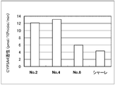
- FIG. 17 shows cytochrome 3A4 enzyme activity in cells when Hc cells were cultured using 6 as a scaffold.
- hepatoblasts derived from Hc cells were treated with functional nonwoven fabric No. 1-No.
- FIG. 4 shows cytochrome 3A4 enzyme activity when 6 is maintained as a scaffold.
- Nonwoven fabric No. 2 and No. When cultured with 4 hepatoblasts expressed high function (FIG. 17). On the other hand, no. In case of 5, the function of hepatoblasts was low (bottom of FIG. 17). The cell density (arrival density) was not different before and after maturation from Hc cells to hepatoblasts.
- FIG. 19 shows the cytochrome 3A4 enzyme activity in the cells when cultured using the nonwoven fabric of No. 6 (control: petri dish only).
- the cell expresses a high function, and has a nonwoven fabric No. In the case of 6 and petri dish, only a low function was expressed (FIG. 19).
- FIG. 20 shows the daily change in cell density when cultured using the nonwoven fabric of No. 6. No. 2 to No. No. 5 compared with the nonwoven fabric of No. 5. A good growth rate was observed in the nonwoven fabric No. 6, and it was confirmed that the growth rate was suppressed in the nonwoven fabric having a yarn diameter of ⁇ 1000 nm or less. In addition, no. Only the nonwoven fabric of 6 was confirmed to increase the growth rate (results are not shown).
- FIG. 21 shows changes in cell density over time when perfusion culture is performed using the apparatus shown in FIG. It was confirmed that by using the cell culture module of the present invention, Hc cells were grown to a high density of 2.5 ⁇ 10 8 cells / mL by circulating culture.
- FIG. 22 shows the daily change in cell density when the perfusion culture is performed using the apparatus shown in FIG. It was confirmed that by using the cell culture module of the present invention, long-term maintenance culture for 33 days could be performed at the cell density seeded by circulating culture.
- the dissolved oxygen concentration of the line was analyzed during the long-term culture, the cells were maintained while being stably maintained at 5.8 ppm by consuming the initial dissolved oxygen concentration of 6.6 ppm as shown in FIG. It was confirmed that it was made.
- Hc cells By circulating culture with the apparatus using the module for cell culture of the present invention, Hc cells were induced to differentiate into hepatoblasts showing high function (CYP3A4 enzyme activity), and this could be cultured and maintained for a long time. Also, human frozen hepatocytes could be cultured and maintained for a long period of time while maintaining high function by carrying out perfusion culture using an apparatus using the module for cell culture of the present invention.
- the present invention cells can be efficiently cultured for a long period of time while maintaining their original functions. Therefore, the present invention is useful for the construction of a cell culture evaluation system that substitutes for animal experiments for evaluating the efficacy, toxicity, and safety of substances such as pharmaceuticals, chemical substances, and cosmetics.
- 101A, 101B, 101C, 101D Module for cell culture
- 110 Culture place
- 111, 111a, 111b, 113, 113a, 113b Hollow fiber membrane
- 112, 114 Hollow fiber membrane mesh
- 115 Scaffold material
- 102 Internal space
- 152 sealing member
- 163 fastener
- 164 recess
- 201A, 201B module for cell culture
- 210 scaffold material
- 211, 211a, 211b 213, 213a, 213b hollow fiber membrane
- 212, 214 hollow fiber membrane mesh
- 215 fiber assembly
- 202 culture space (culture Area)
Landscapes
- Health & Medical Sciences (AREA)
- Wood Science & Technology (AREA)
- Organic Chemistry (AREA)
- Life Sciences & Earth Sciences (AREA)
- Engineering & Computer Science (AREA)
- Bioinformatics & Cheminformatics (AREA)
- Chemical & Material Sciences (AREA)
- Zoology (AREA)
- Biomedical Technology (AREA)
- Sustainable Development (AREA)
- Microbiology (AREA)
- Biotechnology (AREA)
- Biochemistry (AREA)
- General Engineering & Computer Science (AREA)
- General Health & Medical Sciences (AREA)
- Genetics & Genomics (AREA)
- Clinical Laboratory Science (AREA)
- Immunology (AREA)
- Apparatus Associated With Microorganisms And Enzymes (AREA)
- Micro-Organisms Or Cultivation Processes Thereof (AREA)
Description
本発明は、細胞培養用モジュールに関する。より詳しくは、モジュール内の任意の位置へ任意の大きさの物質を出し入れすることができる細胞培養用モジュール、チューブやシリンジなどの送流手段と液密性あるいは気密性高く接続できる細胞培養用モジュール、及び、細胞を本来の機能を維持したまま効率よく長期間培養することができる細胞培養用モジュール、並びに、前記細胞培養用モジュールを含む細胞培養装置に関する。
培養細胞を用いた薬効、毒性、安全性等の評価試験系は、動物実験に代替する試験方法として重要である。しかしながら、細胞、特に初代細胞を生体外で長期間培養することは必ずしも容易ではない。また、培養細胞を用いた評価試験系では、生体内と同様の機能を保持した細胞を用いる必要があるが、本来の機能を維持しつつ細胞を効率よく分化増殖させることも容易ではない。
生体外で細胞を効率的に培養するためには、培養細胞に栄養と空気(酸素)を補給する必要がある。そのための技術としては、従来から中空糸膜を用いて培養液を供給・排出する方法が知られている(特許文献1~3)。
一方、細胞本来の機能を維持しながら培養するためには、生体内に類似した環境で細胞を培養することが好ましい。そのための技術としては、従来ハイドロキシアパタイトやポリ乳酸等の多孔質材料を足場として、細胞を三次元的に培養する方法が知られている(特許文献4)。
近年では、生体内組織の繊維状の構造を高度に模倣できることから、ナノオーダーの繊維径を有するナノファイバーを、細胞培養や組織形成の足場材料として用いる技術が注目されている(非特許文献1、非特許文献2)。例えば、溶融紡糸によって作製されたナノファイバーを足場材料に用いる方法(特許文献5)や、有機系ナノファイバーを溶媒に分散した混合液を利用してナノファイバーのパターンを形成し、さらに細胞培養に有効な機能性薬剤をこのパターンに吸着させることにより、細胞の接着、増殖、分化を制御する方法が示されている(特許文献6)。
発明者らは、メッシュ状に配置した中空糸膜と、足場材料としてのナノファイバー層とを用いることにより、生体外で効率的に細胞を培養できる細胞培養用モジュールを開発している(特許文献7~10)。このモジュールでは、ナノオーダーの繊維径を有するナノファイバーが生体内類似の環境を創出し、中空糸膜が該環境に培養液と空気(酸素)を補給するとともに、培養細胞からの代謝老廃物の除去を行う。
上記細胞培養用モジュールへ細胞懸濁液や培地(培養液)、ガスなどの流体を導入するため、モジュールを構成する基板に設けられた通流口(開口)にチューブを接続したり、注射針を刺し込んだりすることが行われている。この際、モジュールの内部空間の液密性あるいは気密性を確保するため、通流口をシリコンゴムからなるシートによって封止する技術が提案されている(例えば特許文献10参照)。
高分子,2006, Vol.55, No.3, pp.142
Tissue Engineering, 2005, Vol.11, No.1-2,pp.101
上述のような細胞培養用モジュールでは、外部から内部に物質を導入したり、内部から外部へ物質を取り出したりするために、モジュールを構成する基板に、チューブやシリンジ等を接続可能な開孔(インレットあるいはアウトレット)を設けることが行われている。例えば、物質の導入は、インレットに接続したチューブ等から該物質を含む液体を送液することによって行われている。
これらのインレットあるいはアウトレットは、通常0.5~5mm程度の孔径とされるため、これを超える大きさの物質をモジュールの内部へ導入したり、外部へ排出したりすることはできない。また、これよりも小さな物質であっても、液体の流れにのせて内部へ導入する構成であるため、モジュール内部の任意の位置に物質を配置することはできない。同様に、モジュール内部の任意の物体を選択して外部へ排出させることもできない。
上述のような細胞培養用モジュールを利用することで、生体外での細胞培養技術は一定の成果を挙げている。しかしながら、培養細胞を用いた試験系が、動物実験に代替する評価系として完成するためには、生体内と同様の機能を保持した状態で細胞が培養され、生体組織に類似した系が再現されなければならない。そのための検討は、まだ十分になされていない。
そこで、本発明は、モジュール内の任意の位置へ任意の大きさの物質を出し入れすることができる細胞培養用モジュールを提供することを第1の課題とする。
また本発明は、細胞培養用モジュールにおいて、細胞懸濁液や培地、ガスなどの通流口の封止性を高め、細胞の導入時等に細胞懸濁液等の漏れが生じるのを防止するための技術を提供することを第2の課題とする。
さらに本発明は、脱分化等を抑制し、生体内と同様の機能を保持した状態で細胞を長期間培養でき、動物試験に代替する培養細胞評価系を提供することを第3の課題とする。
上記第1の課題解決のため、本発明は、中空糸膜とが配置された培養場と、該培養場を含む内部空間を構成する枠体と、取り外し可能な蓋体と、を備え、該蓋体が取り付けられる開口が、前記培養場全体を露出可能な大きさで設けられている細胞培養用モジュールを提供する。
この細胞培養用モジュールでは、蓋体を取り外して培養場全体を露出させることで、培養場の任意の位置に物質を導入したり、任意の位置の物質を外部に取り出したりすることが、物質の大きさの制約なく可能とされる。
前記細胞培養用モジュールにおいて、前記蓋体及び/又は枠体は、外部から前記内部空間へ又は前記内部空間から外部へ流体を通流させる通流口を有することが好ましく、該通流口は、外部から前記内部空間へ向かって縮径するメス型ルアーテーパを有することが好ましい。
通流口は1つであっても複数であってもよく、蓋体及び/又は枠体(枠体を構成する2枚の基板あるいは型枠)の任意の位置に設けることができるが、後述のとおり、前記繊維集合体の中心に対して対称に設けられていることが特に好ましい。
第2の課題解決のため、本発明は、2枚の基板と、該基板の間に形成された培養領域内に中空糸膜が配設された培養場と、前記培養領域の外部から内部へ又は内部から外部へ流体を通流させる複数の通流口と、を有し、前記通流口は、前記基板の前記足場材料に対応する位置に配設され、かつ、前記培養領域の外部から内部へ向かって縮径するメス型ルアーテーパを備える細胞培養用モジュールを提供する。
通流口にメス型ルアーテーパを備える細胞培養用モジュールは、オス型ルアーテーパを有する、チューブやシリンジなどの送流手段と液密性あるいは気密性高く接続できる。
前記細胞培養用モジュールにおいて、複数の通流口は、同一の前記基板に設けられていても、異なる前記基板に設けられていてもよいが、異なる基板に設けられていることが好ましい。
本発明の細胞培養用モジュールにおいて、通流口は、培養場の中心に対して対称に設けられていることが好ましい。
本発明の細胞培養用モジュールにおいて、繊維集合体は中空糸膜から分離可能に配置されていることが好ましい。また、前記繊維集合体はナノファイバーからなるものとすることができる。
第3の課題解決のため、本発明は、中空糸膜と、平均直径250nm~950nmのナノファイバーからなる繊維集合体とが、配置された培養場を備える細胞培養用モジュールを提供する。
上記した第1、第2の課題解決のための細胞培養用モジュールにおいても、繊維集合体は平均直径250nm~950nmのナノファイバーからなるものとすることができる。なお、ナノファイバーの平均直径は約300nm又は約600nmがより好ましく、約600nmが特に好ましい。
本発明の細胞培養用モジュールを用いて培養することで、高い活性を有する細胞が得られる。得られる細胞のチトクロム450(CYP)活性は2pmol/106cells/min以上であることが好ましく、3pmol/106cells/min以上であることがより好ましく、4pmol/106cells/min以上であることが特に好ましい。
本発明の細胞培養用モジュールにおいて、中空糸膜は、酸素供給用中空糸膜と培地供給用中空糸膜とからなることが好ましい。酸素供給用中空糸膜は、モジュール内に酸素を供給して吸気を促進させ、培地供給用中空糸膜は、モジュール内に培地を供給して、代謝(栄養添加・老廃物排出)を促進させる。
本発明は、前記細胞培養用モジュールと、酸素供給手段と、培地供給手段とを含む、細胞培養用装置も提供する。
本発明の細胞培養用装置は、さらに、モニター手段と、分析手段と、サンプリング手段から選ばれるいずれか1又は2以上の手段を含んでいてもよい。
本発明により、モジュール内の任意の位置へ任意の大きさの物質を出し入れすることができる細胞培養用モジュールが提供される。さらには、細胞シートのような組織を形成することで、ばらばらの細胞とは異なる挙動を示す細胞塊を培養時の状態で取り出すことが可能となり、精度の高い評価試験が行える。
また本発明により、細胞培養用モジュールの細胞懸濁液や培地、ガスなどの通流口の封止性を高め、細胞の導入時等に細胞懸濁液等の漏れが生じるのを防止するための技術が提供される。
さらに本発明により、細胞をその本来の機能を維持した状態で効率よく長期間培養することができる。本発明の技術は、既存の足場材料やこれを用いた細胞培養用モジュールへの適用が可能であり、これにより、より優れた生体外での薬効、毒性、安全性等の評価が可能となる。
本明細書は、本願の優先権の基礎である特願2012-192980号、特願2012-265436号、特願2013-051179号、及び特願2013-101805号の明細書に記載された内容を包含する。
1.第一実施形態に係る細胞培養用モジュール
(1)枠体及び蓋体の構成
図1に、本発明の第一実施形態に係る細胞培養用モジュール101Aの構成を示す。細胞培養用モジュール101Aは、基板120、130及び型枠140を含んだ枠体、並びに蓋体150(以下「キャップ150」と称する)を含んで構成されている。基板130には、キャップ150が取り付けられる開口131が設けられている。
(1)枠体及び蓋体の構成
図1に、本発明の第一実施形態に係る細胞培養用モジュール101Aの構成を示す。細胞培養用モジュール101Aは、基板120、130及び型枠140を含んだ枠体、並びに蓋体150(以下「キャップ150」と称する)を含んで構成されている。基板130には、キャップ150が取り付けられる開口131が設けられている。
開口131周面(内周面)にはネジ溝132が周設されている。キャップ150は、ネジ山151が周設され、開口131と同径とされた外周面を有している。キャップ150は、ネジ山151とネジ溝132との係合によって、開口131へ取り付けあるいは取り外し可能(スクリューキャップ)とされている。図1Aは、キャップ150の取り外し時の細胞培養用モジュール101Aの断面図を示し、図1Bは、キャップ150の取り外し時の基板120、130及び型枠140の上面図を示す。
キャップ150は、開口131へ取り付けられた状態において、基板120、130及び型枠140とともに、液密な(あるいは気密な)内部空間102(後述の図2B参照)を構成する。図1中符号152は、内部空間102の液密性(あるいは気密性)を高めるための封止部材(例えばOリング等)を示す。封止部材152は、キャップ150の基板130との接触部に配設され、キャップ150の開口131への取り付け時において該接触部を封止する。
内部空間102内には、中空糸膜111a(113a)及び中空糸膜111b(113b)がメッシュ状に配設されて構成された培養場110が位置している。中空糸膜111a(113a)は、型枠140の対向する2辺を貫通して型枠140に挿通されており、ポッティング樹脂によって型枠140に固定されている。同様に、中空糸膜111b(113b)は、型枠140の他の対向する2辺を貫通して型枠140に挿通されて型枠140に固定されている。なお、中空糸膜111a(113a)、111b(113b)及び培養場110の構成については、図3を参照して詳しく後述する。
基板120、130は、中空糸膜111a(113a)、111b(113b)及び型枠140を挟んでしっかりと固定するのに適した強度を有するものであればよく、例えば、アクリル板とされる。基板120、130はそれぞれ一枚のアクリル板等から構成されるものであっても、それぞれ2枚以上のアクリル板等から構成されるものであってもよい。キャップ150も、例えばアクリル板であってよく、一枚あるいは2枚以上のアクリル板等から構成されるものであってよい。
型枠140の材料は、ポッティング樹脂との接着性が充分に得られるものであればよく、例えば、シリコンゴムとされる。また、ポッティング樹脂は、充分な接着性を有するものであればよく、例えば、エポキシ樹脂、ウレタン樹脂、不飽和ポリエステル樹脂、シリコン樹脂等の各種の熱硬化性樹脂や熱可塑性樹脂等が用いられる。
基板130の開口131は、キャップ150の取り外し時において、培養場110全体を露出可能な大きさで設けられている。換言すると、上方視した場合(図1B参照)、開口131は、その内側に培養場110の全体が位置し得るような大きさとされている。
開口131の径Dは、培養場110の径d以上とされていることが好ましい。より具体的には、開口131と培養場110は同心状に配置され、かつそれらの径は開口131の径Dが培養場110の径d以上となるようにされていることが好ましい。換言すれば、上方視した場合(図1B参照)、開口131の開口面積は、培養場110の面積以上とされていることが好ましい。より具体的には、上方視した場合(図1B参照)、開口131と培養場110は、開口131の内側に培養場110の全体が位置するように配設されていることが好ましい。
これにより、細胞培養用モジュール101Aでは、キャップ150の取り外し時において、培養場110全体を外部から視認したり操作したりすることが可能なように露出させることができる。従って、細胞培養用モジュール101Aでは、キャップ150を取り外して培養場110全体を露出させることで、培養場110の任意の位置に物質を導入したり、任意の位置の物質を外部に取り出したりすることが、物質の大きさの制約なく可能とされる。
(2)通流口
次に、図2を参照する。キャップ150は、モジュールの外部から内部空間102へ又は内部空間102から外部へ、細胞懸濁液等の流体を通流させるための通流口153を有していてもよい(図A参照)。通流口153は、キャップ150を貫通して設けられている。通流口153は、キャップ150の取り付け時において、外部と内部空間102とを連絡する。図では、キャップ150に穿設されたネジ溝穴に、ポート(接続部材)154をネジ込んで取り付けることにより、通流口153を構成する例を示した。
次に、図2を参照する。キャップ150は、モジュールの外部から内部空間102へ又は内部空間102から外部へ、細胞懸濁液等の流体を通流させるための通流口153を有していてもよい(図A参照)。通流口153は、キャップ150を貫通して設けられている。通流口153は、キャップ150の取り付け時において、外部と内部空間102とを連絡する。図では、キャップ150に穿設されたネジ溝穴に、ポート(接続部材)154をネジ込んで取り付けることにより、通流口153を構成する例を示した。
図には、キャップ150に通流口153を2つ設けた例を示すが、通流口153は1つ又は3つ以上を設けることができる。また、通流口153は、図2Bに示すように基板120にも設けることができる。通流口153は、細胞懸濁液や培地、ガスなどの流体を、内部空間102の外部から内部へ又は内部から外部へ通流させることができる限りにおいて、キャップ150、基板120、130及び型枠140の任意の位置に任意の数で設けることができる。
ポート154の材質は、特に限定されないが、通常、ポリカーボネート、ポリメタクリル酸メチル樹脂(PMMA)、環状ポリオレフィン、ポリエチレン、ポリスチレン、ポリプロピレン及びポリジメチルシロキサン(PDMS)等とされる。ポート154には、医療分野で汎用される、いわゆるシリンジポートを好適に用いることができる。
ポート154はメス型ルアーテーパを備え、その内壁が内部空間102の外部から内部へ向かう方向に徐々に縮径されていることが好ましい。これによって、ポート154は、オス型ルアーテーパを有する、チューブやシリンジなどの送流手段と液密性良く接続される。メス型及びオス型ルアーテーパのテーパ角度や大きさ等の規格は、従来公知のものを適用できる。
通流口153の大きさや形状は、特に限定されないが、例えば円形で、直径が500μm~5mm程度とされる。ポート154のメス型ルアーテーパは、その内壁の少なくとも一部に、オス型ルアーテーパを有する送流手段を刺し込み可能に設けられていればよいものとする。
(3)培養場
次に、図3を参照して、培養場110の構成を説明する。培養場110は、中空糸膜111a、111b(中空糸膜111a、111bを併せて中空糸膜111と称する)がメッシュ状に配置された中空糸膜メッシュ112と、繊維集合体からなる足場材料115と、中空糸膜113a、113b(中空糸膜113a、113bを併せて中空糸膜113と称する)がメッシュ状に配置された中空糸膜メッシュ114とが、この順に積層されている。
次に、図3を参照して、培養場110の構成を説明する。培養場110は、中空糸膜111a、111b(中空糸膜111a、111bを併せて中空糸膜111と称する)がメッシュ状に配置された中空糸膜メッシュ112と、繊維集合体からなる足場材料115と、中空糸膜113a、113b(中空糸膜113a、113bを併せて中空糸膜113と称する)がメッシュ状に配置された中空糸膜メッシュ114とが、この順に積層されている。
(3-1)中空糸膜
中空糸膜メッシュ112を形成する中空糸膜111の膜基材ポリマーは、中空糸膜上に成形できるものであればよく、例えば、ポリエチレン、ポリプロピレン等のポリオレフィン、ポリスルフォン、ポリアリルスルフォン、ポリエーテルスルフォン、ポリアクリロニトリル、セルロースアセテート、ポリフッ化ビニリデン、これらの2種類以上を混合した混合物等が挙げられる。
中空糸膜メッシュ112を形成する中空糸膜111の膜基材ポリマーは、中空糸膜上に成形できるものであればよく、例えば、ポリエチレン、ポリプロピレン等のポリオレフィン、ポリスルフォン、ポリアリルスルフォン、ポリエーテルスルフォン、ポリアクリロニトリル、セルロースアセテート、ポリフッ化ビニリデン、これらの2種類以上を混合した混合物等が挙げられる。
中空糸膜111の外径は、50~3000μmが好ましく、100~2000μmがより好ましい。外径が50μm以上であれば、中空糸膜111において充分な大きさの中空部分を確保しやすいため、培養液を送液する際の差圧が大きくなったり、代謝老廃物の除去が不充分になったりすることを抑制しやすい。また、外径が3000μm以下であれば、単位体積あたりの中空糸膜111の表面積をより大きくすることができるため、培養細胞に充分な栄養及びガスを供給することが容易になる。
中空糸膜111の膜厚は、5~500μmが好ましい。膜厚が5μm以上であれば、栄養供給やガス供給の際の加圧によって中空糸膜が破壊されることを防止しやすい。また、膜厚が500μm以下であれば、ろ過抵抗がより小さくなるため、培養細胞への栄養供給やガス供給や、培養細胞からの代謝老廃物の除去の効率が向上する。なお、中空糸膜111が多層膜である場合の膜厚は、各層の膜厚の総和(全層の膜厚)である。中空糸膜111の内径は、10μm以上2995μm以下が好ましい。
中空糸膜111としては、精密ろ過膜、限外ろ過膜、ガス分離膜等を用いることができる。これらは必要に応じて適宜選択することができる。物質選択透過性を有する中空糸膜を用いることにより、特定の物質を培養細胞に供給したり、特定の代謝老廃物を培養細胞から除去したりすることができる。また、培養液中の特定成分、化学物質、薬物等の被験物質を培養細胞に効率的に供給することや、老廃物や代謝物を系外に排出させてこれらをモニタリングすることが可能となる。物質選択透過性を有する中空糸膜としては、前記精密ろ過膜や限外ろ過膜を挙げることができ、さらに、膜素材そのものに物質選択透過性を有する中空糸膜や、中空部分に選択透過性を有する物質が充填された多孔質中空糸膜を挙げることができる。
また、ガス分離膜を用いることにより、培養細胞に空気、酸素、及びその他のガスを効率的、かつ選択的に供給することができる。ガス供給は多孔質中空糸膜を用いて行ってもよく、この場合、ガス分離機能を有する非多孔性の膜基材を、多孔性の膜基材で支持した中空糸膜が好ましい。このようなガス分離機能を有する中空糸膜を用いることにより、培養液中にバブルレスでガスを供給できるので、培養細胞へのダメージを防止しやすい。また、培養液等の液体が中空糸膜の中空部分に入り込んで該中空部を閉塞することを防止しやすい。
また、中空糸膜111は、親水化処理されていることが好ましい。中空糸膜を親水化処理することにより、培養細胞への培養液等の液体成分の供給が容易になり、また中空糸膜表面への細胞接着の抑制も容易になる。中空糸膜を親水化処理する方法としては、例えば、中空糸膜をエチレン-ビニルアルコール共重合体等の親水性高分子や、グリセリン、エタノールで処理する方法が挙げられる。
また、中空糸膜メッシュ112には、2種類以上の中空糸膜を用いることもできる。例えば、栄養の供給を行う精密ろ過膜、ガスの供給を行うガス分離膜、培養細胞への特定成分の供給あるいは培養細胞からの特定の代謝老廃物の排出を行う物質選択透過性を有する中空糸膜を、任意に組み合わせて用いることができる。
中空糸膜メッシュ112は、複数の中空糸膜を網目が形成するようにメッシュ状に配置したものである。中空糸膜メッシュ112の形態としては、例えば、複数の中空糸膜111aを所定の間隔で平行に配置してシート状とし、それら中空糸膜111aに対して直交する方向に沿って複数の中空糸膜111bを所定の間隔で平行に配置してシート状とすることにより、メッシュ状とした形態が挙げられる(図3A)。中空糸膜メッシュ112における中空糸膜111からなるシートの層数は特に制限されず、2~10層が好ましい。この例では、シートは2層(中空糸膜111aからなる層と中空糸膜111bからなる層)である。
中空糸膜メッシュ114及び中空糸膜113は、中空糸膜メッシュ112及び中空糸膜111と同じものを用いることができ、好ましい形態も同じである。
中空糸膜メッシュ112、114の形態は、中空糸膜111、113を介する栄養や気体の供給、代謝老廃物の除去に応じて選択すればよく、中空糸膜111、113をモジュール化する際のポート部の設計にも依存する。培養場110では、中空糸膜メッシュ112の中空糸膜111aと中空糸膜メッシュ114の中空糸膜113aは同一種類の中空糸膜であることが好ましい。同様に、中空糸膜メッシュ112の中空糸膜111bと中空糸膜メッシュ114の中空糸膜113bは同一種類の中空糸膜であることが好ましい。このような形態とすることで、中空糸膜111、113をモジュール化する際に、例えば中空糸膜111a及び中空糸膜113aを集結させて一つのポート部に繋いでガス供給用中空糸膜とし、中空糸膜111b及び中空糸膜113bを集結させて他のポート部につないで培地供給用中空糸膜として用いることができる。
(3-2)足場材料
足場材料115を構成する繊維集合体には、ナノファイバーの集合体が好適に用いられる。ナノファイバーの集合体は、基材上で、エレクトロスピニング(電界紡糸)により形成されたものであることが好ましい。基材は、特に制限されず、エレクトロスピニングにより表面にナノファイバーの集合体を形成できるものであればよく、例えば、アルミ箔等が挙げられる。
足場材料115を構成する繊維集合体には、ナノファイバーの集合体が好適に用いられる。ナノファイバーの集合体は、基材上で、エレクトロスピニング(電界紡糸)により形成されたものであることが好ましい。基材は、特に制限されず、エレクトロスピニングにより表面にナノファイバーの集合体を形成できるものであればよく、例えば、アルミ箔等が挙げられる。
ナノファイバーの材質は、紡糸が容易である点から、溶剤可溶性のポリマーであることが好ましい。特にエレクトロスピニングが可能な溶剤可溶性のポリマーとしては、例えば、ナイロン4,6、ナイロン6、ナイロン6,6、ナイロン12、ポリアクリル酸、ポリアクリロニトリル、ポリアミド、ポリカーボネート、ポリエーテルイミド、ポリエチレンオキサイド、ポリエチレンテレフタレート、ポリスチレン、スチレン-ブタジエン共重合体、ポリスルフォン、ポリウレタン、ポリビニルアルコール、ポリ塩化ビニル、ポリビニルピロリドン、ポリフッ化ビニリデン、ポリカプロラクトン、ポリ乳酸、シルク、酢酸セルロース、キトサン、コラーゲン等が挙げられる。しかし、これらに限定されるものではなく、これらのポリマーの混合物や、無機物や炭素材料を含有させたものであってもよい。
また、ポリマーの分子量は特に限定されないが、分子量が低すぎると曳糸性が低下するおそれがあり、分子量が高すぎると粘度が高くなって紡糸が困難になるおそれがある。また、溶剤に不溶なポリマーであっても、レーザーエレクトロスピニング法を適用する場合は熱可塑性ポリマーを用いることができる。レーザーエレクトロスピニング法に適用できる熱可塑性ポリマーとしては、例えば、ポリエチレンテレフタレートが挙げられる。
ナノファイバー(単繊維)の平均直径(糸径)は250nm~950nmが好ましく、約300又は約600nmがより好ましく、約600nmがさらに好ましい。この範囲の糸径を有するナノファイバーを用いれば、細胞を高い活性で長期間培養することができる。得られる細胞のチトクロームP450(CYP)活性は2以上であることが好ましく、3以上であることがより好ましく、4以上であることが特に好ましい。
なお、ナノファイバーの単繊維の直径は、上記特許文献10に記載の方法により測定することができる。例えば、ナノファイバーの単繊維の平均直径は、例えば、以下のようにして測定することができる。ナノファイバー、又はその集合体(ナノファイバー層)の表面を電子顕微鏡により観察し、得られた電子顕微鏡写真中の任意の20本のナノファイバー表面の幅を計測し、その平均をナノファイバーの単繊維の直径とする。電子顕微鏡としては、走査型電子顕微鏡(SEM)が好ましい。観察倍率は5000倍~5万倍が好ましい。観察倍率が5000倍以上であれば、ナノファイバーの直径の決定が容易になる。また、単繊維の直径を求める際には、画像解析ソフトを用いることが好ましい。画像解析ソフトによって得られるナノファイバーの単繊維の直径は、画像解析のための画質調整、画像解析ソフトの種類等によって若干変動があるが、その差は通常の実験誤差の範囲内である。
繊維集合体の厚みは、0.5~100μmが好ましく、1~50μmがより好ましい。厚みが0.5μm以上であれば、繊維集合体115を中空糸膜メッシュ間に配置するのが容易になる。厚みが100μm以下であれば、栄養やガスの供給や代謝老廃物の除去が足場材料15に接着した細胞全体に均一に行えるため、細胞培養の効率が向上する。
足場材料115に生理活性物質を吸着または固定させることにより、培養細胞の接着、増殖、分化、機能発現の制御を行うことができる。生理活性物質としては、機能性ポリマー、アミノ酸、タンパク質、糖鎖、ビタミン類等が挙げられる。特に、細胞培養に有効な生理活性物質、例えば培養細胞の増殖、分化、機能発現に重要な役割を有する生理活性物質の総称であるサイトカインを用いると効果的である。サイトカインとしては、インターロイキン、増血因子、増殖因子等が挙げられる。また、細胞-細胞外マトリックス、細胞-細胞間の接着に関与するインテグリン、カドヘリン等の細胞接着基質を用いることも効果的である。また、薬剤や化学物質等の被験物質を足場材料115に吸着または固定することにより、細胞培養試験を行うことも可能である。
培養場110は、以上説明した中空糸膜メッシュ112と中空糸膜メッシュ114との間に、足場材料115が配置された積層体を有する。このように、ナノファイバー層を中空糸膜メッシュ間に配置することにより、足場材料115を中空糸膜メッシュ112、114に強固に固定することができ、培養細胞への栄養やガスの供給や、細胞培養からの代謝老廃物の除去をより安定して行うことができる。また、足場材料115を中空糸膜メッシュ112、114間に配置することで、足場材料115に接着させた培養細胞と中空糸膜111、113との距離が近くなるため、培養細胞への栄養やガスの供給や、細胞培養からの代謝老廃物の除去をより高い効率で行うことができ、培養細胞のネクローシスが減少して細胞培養の効率が向上する。
培養場110の大きさは、薬物試験に必要な細胞個数が確保できる大きさであればよく、1m2~0.1cm2が好ましく、600cm2~0.2cm2がより好ましく、59cm2~0.35cm2が特に好ましい。この範囲内であると足場材の均一性が上昇する。
なお、本発明に係る細胞培養用モジュールにおいて、培養場10の中空糸膜メッシュ112、114と足場材料115の積層数は特に限定されず、中空糸膜メッシュ114、足場材料115、中空糸膜メッシュ112、足場材料115、中空糸膜メッシュ112がこの順に積層されてもよく、これ以上の数の中空糸膜メッシュ112、114と足場材料115が積層されもよいものとする。
細胞培養用モジュール101Aでは、上述のポート154に、例えばチューブ等を接続することにより、栄養やガスの供給や、代謝老廃物の除去の行う経路として、中空糸膜メッシュ112、114の中空糸膜111、113以外の第3の経路を設けることができる。そのため、中空糸膜のみを用いて栄養やガスを供給したり、代謝老廃物を除去したりする場合に比べて、より多くの条件でかつそれらの条件を独立に制御しながらの細胞培養を、より簡便に行うことができる。
(4)変形例
(4-1)蓋体の変形例
上記では、基板130の開口131周面(内周面)にネジ溝132を設け、キャップ150の外周面にネジ山151を設けて、キャップ150の開口131への着脱を行う例を説明した。この形態は、構造が単純で加工が容易であり、キャップ150の着脱も容易である。また、モジュールのサイズも小さくできる。
(4-1)蓋体の変形例
上記では、基板130の開口131周面(内周面)にネジ溝132を設け、キャップ150の外周面にネジ山151を設けて、キャップ150の開口131への着脱を行う例を説明した。この形態は、構造が単純で加工が容易であり、キャップ150の着脱も容易である。また、モジュールのサイズも小さくできる。
キャップ150の開口131への着脱は、図4に示すように、基板130の開口131の外周面にネジ溝132を設け、キャップ150の内周面にネジ山151を設けることによって行ってもよい。図4Aは、キャップ150の取り外し時の細胞培養用モジュール101Aの断面図を示す。
この変形例では、ネジ山151とネジ溝132が、内部空間102に導入される培地等と接触することがない。このため、乾燥した培地等によるネジ山151とネジ溝132との固着を防止して、キャップ150の着脱操作性を高めることができる。
(4-2)培養場の変形例
また、上記では、中空糸膜メッシュ112と中空糸膜メッシュ114との間に足場材料115を配して培養場110を構成する例を説明した。培養場110は、図5に示すように、中空糸膜メッシュ114、中空糸膜メッシュ112及び足場材料115をこの順に積層して構成してもよい。これにより、足場材料115を中空糸膜メッシュ112上に分離可能に配置することができる。従って、キャップ50を取り外して培養場110全体を露出させれば、培養場110から中空糸膜メッシュ112上の足場材料115をそのまま外部に取り出すことできる。
また、上記では、中空糸膜メッシュ112と中空糸膜メッシュ114との間に足場材料115を配して培養場110を構成する例を説明した。培養場110は、図5に示すように、中空糸膜メッシュ114、中空糸膜メッシュ112及び足場材料115をこの順に積層して構成してもよい。これにより、足場材料115を中空糸膜メッシュ112上に分離可能に配置することができる。従って、キャップ50を取り外して培養場110全体を露出させれば、培養場110から中空糸膜メッシュ112上の足場材料115をそのまま外部に取り出すことできる。
2.第一実施形態に係る細胞培養用モジュールにおける細胞培養方法
上述の細胞培養用モジュール101Aを用いた細胞培養方法について説明する。
上述の細胞培養用モジュール101Aを用いた細胞培養方法について説明する。
(1)細胞導入手順
まず、培養場110に細胞を導入する。細胞の導入は、キャップ150を取り外した状態で行うことができる(図1参照)。キャップ150を取り外した状態では、開口131を通して培養場110全体が露出される。このため、培養場110全体を視認しながら、細胞を培養場110上の任意の位置に細胞を導入することが可能である。細胞の導入は、例えばピペット等を開口231から内部空間102内に挿入し、培養場110上の任意の位置に細胞懸濁液を滴下することによって行う。細胞懸濁液とともに試験物質等の物質を導入してもよい。例えばピンセット等を培養空間102内に挿入し、固形物質を培養場110上に配置することによって、物質の大きさに制約なく任意の位置に導入できる。
まず、培養場110に細胞を導入する。細胞の導入は、キャップ150を取り外した状態で行うことができる(図1参照)。キャップ150を取り外した状態では、開口131を通して培養場110全体が露出される。このため、培養場110全体を視認しながら、細胞を培養場110上の任意の位置に細胞を導入することが可能である。細胞の導入は、例えばピペット等を開口231から内部空間102内に挿入し、培養場110上の任意の位置に細胞懸濁液を滴下することによって行う。細胞懸濁液とともに試験物質等の物質を導入してもよい。例えばピンセット等を培養空間102内に挿入し、固形物質を培養場110上に配置することによって、物質の大きさに制約なく任意の位置に導入できる。
細胞の導入は、キャップ150に通流口153を設ける場合(図2参照)には、ポート154に細胞懸濁液の送液手段を接続して行ってもよい。通流口153から細胞懸濁液を送液することにより、内部空間102に細胞懸濁液の流れが形成され、該流れによって細胞が運搬されて培養場110上に分散される。ただし、この場合には、細胞を培養場110上の任意の位置にのみ導入することは難しい。また、細胞懸濁液とともに試験物質等の物質を導入してもよいが、この場合には、物質は溶液又は分散液で導入される必要があり、物質を培養場110上の任意の位置のみに導入することは難しい。
(2)培養手順
細胞の導入完了後、例えば中空糸膜111a及び中空糸膜113aを集結させて一つのポート部に繋いでガス供給を行い、中空糸膜111b及び中空糸膜113bを集結させて他のポート部につないで培地供給を行って細胞培養を行う。
細胞の導入完了後、例えば中空糸膜111a及び中空糸膜113aを集結させて一つのポート部に繋いでガス供給を行い、中空糸膜111b及び中空糸膜113bを集結させて他のポート部につないで培地供給を行って細胞培養を行う。
細胞培養は、具体的には、例えば中空糸膜111a、113aとしてガス分離膜である中空糸膜、中空糸膜111b、113bとして物質選択透過性を有する中空糸膜を用い、中空糸膜111a、113aの片端より酸素を含むガスを供給しつつ、他方の端部より該ガスを排出させる。また、中空糸膜111b、113bの片端より培養細胞の栄養を供給し、他方の端部より該培養細胞の老廃物や代謝物を排出させる。これにより、排出される成分をオンラインで分析し、培養細胞を培養しながら連続的に培養細胞の生育状況を評価することも可能である。
また、培養細胞に、中空糸膜111b、113bの片端より被験物質を投与し、老廃物や代謝物を含む溶液を中空糸膜111b、113bの他方の端部より排出させ、この溶液を分析しモニタリングすることによって、被験物質を投与した場合の培養細胞が受けるストレスや培養細胞の状態を経時的に評価できる。
(3)細胞回収手順
培養後の細胞は、再度キャップ150を取り外して回収することができる。キャップ150を取り外した状態では、開口131を通して培養場110全体が露出される。このため、培養場110全体を視認しながら、培養場110上の任意の位置の細胞を選択的に回収することが可能である。細胞の回収は、例えばピペットを開口131から培養空間102内に挿入し、培養場110上の任意の位置の細胞を吸引することによって行う。あるいは、例えばスパチュラを培養空間102内に挿入し、培養場110上の任意の位置の細胞を掻き取って回収することもできる。
培養後の細胞は、再度キャップ150を取り外して回収することができる。キャップ150を取り外した状態では、開口131を通して培養場110全体が露出される。このため、培養場110全体を視認しながら、培養場110上の任意の位置の細胞を選択的に回収することが可能である。細胞の回収は、例えばピペットを開口131から培養空間102内に挿入し、培養場110上の任意の位置の細胞を吸引することによって行う。あるいは、例えばスパチュラを培養空間102内に挿入し、培養場110上の任意の位置の細胞を掻き取って回収することもできる。
さらに、細胞の回収は、足場材料115を中空糸膜メッシュ112上に分離可能に配置した場合には、細胞が付着した足場材料115をそのまま外部に取り出すことによって行ってもよい。
また、培養場110に試験物質等の物質が導入されている場合には、細胞とともに該物質の回収を行うこともできる。例えばピンセット等で培養場110上の任意の位置の固形物質を選択的に取り出すことによって、物質の大きさに制約なく任意の位置から回収できる。
3.第二実施形態に係る細胞培養用モジュール
図6に、本発明の第二実施形態に係る細胞培養用モジュール101Bの構成を示す。上述した第一実施形態に係る細胞培養モジュール101Aでは、キャップ150の開口131への着脱を、開口131のネジ溝132と、キャップ150のネジ山151との係合によって行う構成を説明した。本実施形態に係る細胞培養用モジュール101Bは、キャップ150の開口131への着脱をネジ161とネジ穴162とによって行う構成となっている点で、細胞培養モジュール101Aと異なっている。
図6に、本発明の第二実施形態に係る細胞培養用モジュール101Bの構成を示す。上述した第一実施形態に係る細胞培養モジュール101Aでは、キャップ150の開口131への着脱を、開口131のネジ溝132と、キャップ150のネジ山151との係合によって行う構成を説明した。本実施形態に係る細胞培養用モジュール101Bは、キャップ150の開口131への着脱をネジ161とネジ穴162とによって行う構成となっている点で、細胞培養モジュール101Aと異なっている。
ネジ穴162は、キャップ150、基板130、型枠140及び基板120を貫通して設けられている。また、ネジ穴162は、開口131及び内部空間102、中空糸膜111a(113a)及び中空糸膜111b(113b)に干渉しない位置(好ましくは図に示すように細胞培養モジュール1Bの四隅)に設けられている。開口131へのキャップ150の取り付けは、キャップ150、基板130、型枠140及び基板120を、それぞれに穿設されたねじ穴162の位置を一致させるように重ね合わせ、ネジ穴162にネジ161をねじ込むことによって行う。
細胞培養用モジュール101Bは、加工が容易であり、細胞培養用モジュール101Aで生じ得る培地の乾燥等によるネジ山51とネジ溝132との固着の問題がない。なお、ネジ穴162は、開口131へのキャップ150の取り付けのため、キャップ150を貫通し、基板130の少なくとも一部にまで穿設されていることが必要である。しかし、ネジ穴162は、基板130全部、さらには型枠140及び基板120にまで穿設されていることは必須とはならない。また、ネジ穴162の数及び位置についても、図に示した形態に限られず、適宜変更が可能である。
4.第三実施形態に係る細胞培養用モジュール
図7に、本発明の第三実施形態に係る細胞培養用モジュール101Cの構成を示す。細胞培養用モジュール101Cは、キャップ150の開口131への着脱を、基板130に設けた係合穴133と、キャップ150に設けた係合ツメ155との係合によって行う構成となっている点で、上述した第一実施形態に係る細胞培養モジュール101Aと異なっている。
図7に、本発明の第三実施形態に係る細胞培養用モジュール101Cの構成を示す。細胞培養用モジュール101Cは、キャップ150の開口131への着脱を、基板130に設けた係合穴133と、キャップ150に設けた係合ツメ155との係合によって行う構成となっている点で、上述した第一実施形態に係る細胞培養モジュール101Aと異なっている。
係合穴133は、基板130の開口131周縁部に設けられている。また、係合ツメ155は、開口131にキャップ150を閉蓋した際に、係合穴133の位置に対応し得る位置に設けられている。係合穴133及び係合ツメ155は、係合可能な形状を有していればよいが、例えば図に示すように、係合ツメ155を係合穴133に挿入した後、キャップ150を回転させることによって係合ツメ155を係合穴133に係止させる構造を一般に採用可能である。
5.第四実施形態に係る細胞培養用モジュール
図8に、本発明の第四実施形態に係る細胞培養用モジュール101Dの構成を示す。細胞培養用モジュール101Dは、キャップ150の開口131への着脱を、留め具163によって行う構成となっている点で、上述した第一実施形態に係る細胞培養モジュール101Aと異なっている。
図8に、本発明の第四実施形態に係る細胞培養用モジュール101Dの構成を示す。細胞培養用モジュール101Dは、キャップ150の開口131への着脱を、留め具163によって行う構成となっている点で、上述した第一実施形態に係る細胞培養モジュール101Aと異なっている。
留め具163には、例えば、開口131を閉蓋したキャップ150と基板120とを挟み込んで保持するものを採用できる。この場合、キャップ150の上面と基板120の下面には、留め具163をはめ込むための凹部(図中符号164参照)を設けてもよい。
細胞培養用モジュール101C、101Dは、キャップ150の着脱操作性に優れる。また、細胞培養用モジュール101C、101Dでは、細胞培養用モジュール101Aで生じ得る培地の乾燥等によるネジ山151とネジ溝132との固着の問題がない。
以上のように、本発明に係る細胞培養用モジュールでは、キャップ150の取り外し時において、培養場110全体を外部から視認したり操作したりすることが可能なように露出させることができる。このため、本発明に係る細胞培養用モジュールでは、キャップ150を取り外して培養場110全体を露出させることで、培養場110の任意の位置に物質を導入したり、任意の位置の物質を外部に取り出したりすることが、物質の大きさの制約なく可能とされる。また、内部空間102内にpH測定や溶存酸素濃度測定などのためのプローブを挿入し、計測を行うことも可能となる。
6.第五実施形態に係る細胞培養用モジュール
(1)概略構成
図8に、本発明の第五実施形態に係る細胞培養用モジュール201Aの構成を示す。細胞培養用モジュール201Aでは、基板220、230と型枠240によって液密な(あるいは気密な)培養空間(培養領域)202が構成されている。培養空間202には、中空糸膜と繊維集合体とからなる足場材料210が配設されている。足場材料210はポッティング樹脂で型枠240に固定されており、基板220、230はこれらを挟み込んで培養空間202を形成している。
(1)概略構成
図8に、本発明の第五実施形態に係る細胞培養用モジュール201Aの構成を示す。細胞培養用モジュール201Aでは、基板220、230と型枠240によって液密な(あるいは気密な)培養空間(培養領域)202が構成されている。培養空間202には、中空糸膜と繊維集合体とからなる足場材料210が配設されている。足場材料210はポッティング樹脂で型枠240に固定されており、基板220、230はこれらを挟み込んで培養空間202を形成している。
基板220、230は、足場材料210及び型枠240を挟んでしっかりと固定するのに適した強度を有するものであればよく、例えば、アクリル板とされる。細胞培養用モジュール201Aにおいて、基板220、230はそれぞれ一枚のアクリル板等から構成されるものであっても、それぞれ2枚以上のアクリル板等から構成されるものであってもよい。また、細胞培養用モジュール201Aにおいて複数の培養空間202が設けられる場合には、これらを形成する基板220、230もそれぞれ2以上存在し得る。
型枠240の材料は、ポッティング樹脂との接着性が充分に得られるものであればよく、例えば、シリコンゴムとされる。また、ポッティング樹脂は、充分な接着性を有するものであればよく、例えば、エポキシ樹脂、ウレタン樹脂、不飽和ポリエステル樹脂、シリコン樹脂等の各種の熱硬化性樹脂や熱可塑性樹脂等が用いられる。
(2)通流口
基板220にはねじ穴221が穿設されている。ねじ穴221は、基板層220を貫通し、細胞培養用モジュール201Aの外部と内部の培養空間202とを連絡している。ねじ穴221の一部にはねじが切られており、ポート(接続部材)222がねじ込まれて取り付けられている。
基板220にはねじ穴221が穿設されている。ねじ穴221は、基板層220を貫通し、細胞培養用モジュール201Aの外部と内部の培養空間202とを連絡している。ねじ穴221の一部にはねじが切られており、ポート(接続部材)222がねじ込まれて取り付けられている。
ねじ穴221及びポート222は、細胞懸濁液や培地、ガスなどの流体を、培養空間202の外部から内部へ又は内部から外部へ通流させるための通流口を構成している。ねじ穴221及びポート222、並びにこれらから構成された通流口は、基板220において足場材料210(具体的には後述する繊維集合体215)に対応する位置に配設されている。また、2つの通流口は、足場材料210(具体的には後述する繊維集合体215)の中心に対して対称(点対称)となる位置に配設されている。
ポート222の材質は、特に限定されないが、通常、ポリカーボネート、ポリメタクリル酸メチル樹脂(PMMA)、環状ポリオレフィン、ポリエチレン、ポリスチレン、ポリプロピレン及びポリジメチルシロキサン(PDMS)等とされる。ポート222には、医療分野で汎用される、いわゆるシリンジポートを好適に用いることができる。
基板230にはねじ穴231が穿設されており、ねじ穴231にはポート232が取り付けられている。ねじ穴231及びポート232の構成は、ねじ穴221及びポート222と同様である。
ポート222及びポート232はメス型ルアーテーパを備え、その内壁が培養空間202の外部から内部へ向かう方向に徐々に縮径されている。これによって、ポート222及びポート232は、オス型ルアーテーパを有する、チューブやシリンジなどの送流手段と液密性良く接続される。メス型及びオス型ルアーテーパのテーパ角度や大きさ等の規格は、従来公知のものを適用できる。
ねじ穴221、231及びポート222、232の大きさや形状も、特に限定されないが、例えば円形で、直径が500μm~5mm程度とされる。ポート222及びポート232のメス型ルアーテーパは、それらの内壁の少なくとも一部に、オス型ルアーテーパを有する送流手段を刺し込み可能に設けられていればよいものとする。なお、ねじ穴221、231は、細胞培養用モジュール201Aの外部と培養空間202内とを連絡し、かつポート222、232の取り付けが可能であれば、きり穴であってもよいものとする。
(3)ルアーテーパによる接続
図9に、シリンジを送液手段として用いる場合を例にとり、ポートとの接続態様を示す。図中符号205で示されるシリンジでは、プランジャ253をシリンジ本体252に押し込むことにより、シリンジ本体252の内部に保持された流体(ここでは、細胞懸濁液を例とする)を先端部251の開口から外部に排出できる。シリンジ205には、医療分野で汎用される使い捨ての注射筒を好適に用いることができる。
図9に、シリンジを送液手段として用いる場合を例にとり、ポートとの接続態様を示す。図中符号205で示されるシリンジでは、プランジャ253をシリンジ本体252に押し込むことにより、シリンジ本体252の内部に保持された流体(ここでは、細胞懸濁液を例とする)を先端部251の開口から外部に排出できる。シリンジ205には、医療分野で汎用される使い捨ての注射筒を好適に用いることができる。
シリンジ205の先端部251は、細胞培養用モジュール201Aのポート222及び/又は、シリンジ本体252との接続部から開口に向かって縮径するオス型ルアーテーパを備えている。シリンジ205の先端部251のオス型ルアーテーパと、細胞培養用モジュール201Aのポート222及び/又はポート232のメス型ルアーテーパとは、ほぼ同一の形状とされており、嵌合可能とされている。従って、シリンジ205と細胞培養用モジュール201Aとは、先端部251をポート222及び/又はポート232に差し込むことによって簡単に液密に接続できる。これにより、細胞培養用モジュール201Aでは、シリンジ205内の細胞懸濁液を、漏れを生じることなく、培養空間202内に導入することが可能とされる。
さらに、ポート222及びポート232は、ルアープラグ(封止部材)によって簡単に封止することができる(図10参照)。図13Aは、ポート222及びポート232に着脱可能に被せることが可能なルアープラグ223a、233aを示している。また、図10Bには、ポート222及びポート232のメス型ルアーテーパに嵌合可能なオス型ルアーテーパを備えたルアープラグ223b、233bを示した。
これらのルアープラグによれば、シリンジ205内の細胞懸濁液を培養空間202内に導入した後、シリンジ205を抜き取ったポート222及び/又はポート232を簡単に封止できる。なお、ルアープラグは未使用状態の細胞培養用モジュール201Aのポート222及びポート232に取り付けておくことも可能である。また、使用中の細胞培養用モジュール201Aにおいても、シリンジ205等の取り付けが不要の際には、ポート222及びポート232に取り付けておくことができる。
図9では、ポート222及びポート232に接続される送流手段としてシリンジ205を例に説明したが、ルアーテーパによる同様の接続は、培地などの液体及び酸素などのガスを含む種々の流体を送流するためのチューブやポンプ、活栓などの種々の送流手段との間で行い得る。チューブやポンプを接続する場合には、ポート222又はポート232のメス型ルアーテーパに嵌合可能なオス型ルアーテーパを備えたルアーフィッティングを介して、ポート222又はポート232に接続する。また、活栓には、ポート222又はポート232のメス型ルアーテーパに嵌合可能なオス型ルアーテーパを備えたものを用いればよい。
ルアーテーパによる送流手段との接続により、細胞培養用モジュール201Aでは、硬化性樹脂などを用いて接続部を封止することなく、細胞懸濁液や培地、ガスなどの流体を簡便に導入(又は排出)することが可能となった。
(4)足場材料
次に、図11を参照して、足場材料210の構成を説明する。足場材料210は、中空糸膜211a、211b(211)がメッシュ状に配置された中空糸膜メッシュ212と、繊維集合体215と、中空糸膜213a、213b(213)がメッシュ状に配置された中空糸膜メッシュ214とが、この順に積層されている。
次に、図11を参照して、足場材料210の構成を説明する。足場材料210は、中空糸膜211a、211b(211)がメッシュ状に配置された中空糸膜メッシュ212と、繊維集合体215と、中空糸膜213a、213b(213)がメッシュ状に配置された中空糸膜メッシュ214とが、この順に積層されている。
(4-1)中空糸膜
中空糸膜メッシュ212を形成する中空糸膜111の膜基材ポリマー、外径、膜厚等については、第一実施形態で記載したとおりである。
中空糸膜メッシュ212を形成する中空糸膜111の膜基材ポリマー、外径、膜厚等については、第一実施形態で記載したとおりである。
中空糸膜メッシュ212は、複数の中空糸膜を網目が形成するようにメッシュ状に配置したものである。中空糸膜メッシュ212の形態としては、例えば、複数の中空糸膜211a(中空糸膜211)を所定の間隔で平行に配置してシート状とし、それら中空糸膜211aに対して直交する方向に沿って複数の中空糸膜211b(中空糸膜211)を所定の間隔で平行に配置してシート状とすることにより、メッシュ状とした形態が挙げられる(図11A)。中空糸膜メッシュ212における中空糸膜211からなるシートの層数は特に制限されず、2~10層が好ましい。この例では、シートは2層(中空糸膜211aからなる層と中空糸膜211bからなる層)である。
中空糸膜メッシュ214及び中空糸膜213は、中空糸膜メッシュ212及び中空糸膜211と同じものを用いることができ、好ましい形態も同じである。
中空糸膜メッシュ212、214の形態は、中空糸膜を介する栄養や気体の供給、代謝老廃物の除去に応じて選択すればよく、足場材料210をモジュール化する際のポート部の設計にも依存する。足場材料210では、中空糸膜メッシュ212の中空糸膜211aと中空糸膜メッシュ214の中空糸膜213aは同一種類の中空糸膜であることが好ましい。同様に、中空糸膜メッシュ212の中空糸膜211bと中空糸膜メッシュ214の中空糸膜213bは同一種類の中空糸膜であることが好ましい。このような形態とすることで、足場材料210をモジュール化する際に、例えば中空糸膜211a及び中空糸膜213aを集結させて一つのポート部に繋いでガス供給用中空糸膜とし、中空糸膜211b及び中空糸膜213bを集結させて他のポート部につないで培地供給用中空糸膜として用いることができる。
(4-2)繊維集合体
繊維集合体215には、ナノファイバーの集合体が好適に用いられる。ナノファイバーの集合体の材質、分子量、直径、厚みについては、後述する。
繊維集合体215には、ナノファイバーの集合体が好適に用いられる。ナノファイバーの集合体の材質、分子量、直径、厚みについては、後述する。
足場材料210は、以上説明した中空糸膜メッシュ212と中空糸膜メッシュ214との間に、繊維集合体215が配置された積層体を有する。このように、ナノファイバー層を中空糸膜メッシュ間に配置することにより、ナノファイバーを中空糸膜メッシュに強固に固定することができ、培養細胞への栄養やガスの供給や、細胞培養からの代謝老廃物の除去をより安定して行うことができる。
細胞培養用モジュール201Aでは、上述のポート222,232に、例えばチューブ等を接続することにより、栄養やガスの供給や、代謝老廃物の除去の行う経路として、中空糸膜メッシュ212、214の中空糸膜211、213以外の第3の経路を設けることができる。そのため、中空糸膜のみを用いて栄養やガスを供給したり、代謝老廃物を除去したりする場合に比べて、より多くの条件でかつそれらの条件を独立に制御しながらの細胞培養を、より簡便に行うことができる。
(5)変形例
本実施形態では、基板220に通流口(ねじ穴221及びポート222)を一つ、基板230に通流口(ねじ穴231及びポート232)を一つ配設する例を説明した。本発明に係る細胞培養用モジュールにおいて、通流口は、1つであってもよく、この場合には基板220及び基板230のいずれに配設されてもよい。また、本発明に係る細胞培養用モジュールにおいて、通流口は3つ以上を配設してもよく、この場合には基板220及び基板230にそれぞれ1以上を配設すればよい。
本実施形態では、基板220に通流口(ねじ穴221及びポート222)を一つ、基板230に通流口(ねじ穴231及びポート232)を一つ配設する例を説明した。本発明に係る細胞培養用モジュールにおいて、通流口は、1つであってもよく、この場合には基板220及び基板230のいずれに配設されてもよい。また、本発明に係る細胞培養用モジュールにおいて、通流口は3つ以上を配設してもよく、この場合には基板220及び基板230にそれぞれ1以上を配設すればよい。
また、本実施形態では、ねじ穴221、231とポート222、232によって通流口を構成する例を説明した。本発明に係る細胞培養用モジュールにおいて、通流口は、メス型ルアーテーパを備え、対応するオス型ルアーテーパを備えた送流手段と液密な接続な可能な構成であればよい。通流口の他の形態としては、例えば、基板220、230に穿設される穴そのものを、メス型ルアーテーパを有したものとした形態が挙げられる。
さらに、本発明に係る細胞培養用モジュールにおいて、足場材料210の中空糸膜メッシュと繊維集合体の積層数は特に限定されず、中空糸膜メッシュ、ナノファイバー層、中空糸膜メッシュ、ナノファイバー層、中空糸膜メッシュがこの順に積層された細胞培養足場材料であってもよく、これ以上の数が積層された細胞培養足場材料であってもよいものとする。
7.第五実施形態に係る細胞培養用モジュールにおける細胞培養方法
上述の細胞培養用モジュール201Aを用いた細胞培養方法について、図12を参照しながら説明する。
上述の細胞培養用モジュール201Aを用いた細胞培養方法について、図12を参照しながら説明する。
(1)細胞導入手順
[手順1]
まず、細胞培養用モジュール201Aのポート222、232に細胞懸濁液の送液手段を接続する。図12中では図示を省略するが、送液手段には図9で説明したシリンジ(シリンジ205)を用いるものとして説明する。ただし、送液手段は、チューブやポンプなどであってもよい。
[手順1]
まず、細胞培養用モジュール201Aのポート222、232に細胞懸濁液の送液手段を接続する。図12中では図示を省略するが、送液手段には図9で説明したシリンジ(シリンジ205)を用いるものとして説明する。ただし、送液手段は、チューブやポンプなどであってもよい。
本手順では、シリンジを2つ用意する。一方のシリンジは、シリンジ本体にプランジャを押し込んだ状態とし、ポート222に接続する。もう一方のシリンジは、シリンジ本体に細胞懸濁液を充填した状態で、ポート232に接続する。
ポート222、232とシリンジとの接続は、シリンジの先端部のオス型ルアーテーパを、ポート222、232のメス型ルアーテーパに差し込むことによって液密に行うことができる。
[手順2]
次に、ポート232に接続した細胞懸濁液が充填されたシリンジのプランジャを押し込み、細胞懸濁液を培養空間202内へ導入する(図12A参照)。同時に、ポート222に接続したシリンジのプランジャを引いて、培養空間202内に導入された細胞懸濁液の少なくとも一部を培養空間202からシリンジ本体内へ回収する。
次に、ポート232に接続した細胞懸濁液が充填されたシリンジのプランジャを押し込み、細胞懸濁液を培養空間202内へ導入する(図12A参照)。同時に、ポート222に接続したシリンジのプランジャを引いて、培養空間202内に導入された細胞懸濁液の少なくとも一部を培養空間202からシリンジ本体内へ回収する。
これにより、培養空間202内には、ポート232側からポート222側へ細胞懸濁液の流れが形成される(図12A矢印参照)。ここで先に説明したように、ポート222、232は、基板220、230において足場材料210(具体的には繊維集合体215)に対応する位置に配設されている。このため、培養空間202内に導入された細胞は、上記流れに運搬されて、繊維集合体215上に分散する。
さらに、細胞培養用モジュール201Aでは、ポート222、232は、足場材料210(具体的には繊維集合体215)の中心に対して対称(点対称)となる位置に配設されている。このため、ポート132側からポート222側へ向かう細胞懸濁液の流れを、培養空間202内全体に効果的に発生させることができ、該流れによって細胞を繊維集合体215上に効率よく分散させることが可能である。
[手順3]
ポート232に接続されたシリンジの細胞懸濁液が全てあるいは大部分なくなったら、今度は、ポート222に接続したシリンジのプランジャを押し込み、シリンジ本体内に回収されている細胞懸濁液を再度培養空間202内へ導入する(図12B参照)。同時に、ポート232に接続されたシリンジのプランジャを引いて、培養空間202内に再導入された細胞懸濁液の少なくとも一部を培養空間202からシリンジ本体内へ回収する。
ポート232に接続されたシリンジの細胞懸濁液が全てあるいは大部分なくなったら、今度は、ポート222に接続したシリンジのプランジャを押し込み、シリンジ本体内に回収されている細胞懸濁液を再度培養空間202内へ導入する(図12B参照)。同時に、ポート232に接続されたシリンジのプランジャを引いて、培養空間202内に再導入された細胞懸濁液の少なくとも一部を培養空間202からシリンジ本体内へ回収する。
これにより、培養空間202内には、ポート222側からポート232側へ細胞懸濁液の流れが形成され(図12B矢印参照)、培養空間202内に導入されて繊維集合体215上に分散された細胞が、上記流れに運搬されることによって繊維集合体215上においてさらに均一に分散される。
[手順4]
ポート222に接続されたシリンジの細胞懸濁液が全てあるいは大部分なくなったら、必要に応じて、手順2と手順3を所望の回数繰り返す。手順2及び手順3において、それぞれポート232側からポート222側への流れ及びその逆方向の流れを交互に発生させることで、繊維集合体215上に細胞を万遍なく分散させることができる。
ポート222に接続されたシリンジの細胞懸濁液が全てあるいは大部分なくなったら、必要に応じて、手順2と手順3を所望の回数繰り返す。手順2及び手順3において、それぞれポート232側からポート222側への流れ及びその逆方向の流れを交互に発生させることで、繊維集合体215上に細胞を万遍なく分散させることができる。
手順2と手順3の繰り返し回数は、細胞の種類や懸濁液中の量(濃度)、目的とする培養密度などの条件によって適宜設定され得る。ただし、手順4は必須ではなく、上記条件によっては、手順2、3のみ(手順4なし)でも、細胞を繊維集合体215上に十分に均一に分散させられる場合もある。
[手順5]
最後に、ポート222に接続されたシリンジ及びポート232に接続されたシリンジの両方のプランジャを押し込んで、細胞懸濁液を全て培養空間202内へ導入する。この際、培養空間202の容積を超過した液は、中空糸膜211、213(図11参照)を通って排出される。
最後に、ポート222に接続されたシリンジ及びポート232に接続されたシリンジの両方のプランジャを押し込んで、細胞懸濁液を全て培養空間202内へ導入する。この際、培養空間202の容積を超過した液は、中空糸膜211、213(図11参照)を通って排出される。
以上の手順1~5により、細胞培養用モジュール201A内に、具体的には繊維集合体215上に、細胞を偏在させることなく、均一性の高い濃度分布で細胞導入を行うことが可能となる。
(2)培養手順
細胞の導入完了後、例えば中空糸膜211a及び中空糸膜213aを集結させて一つのポート部に繋いでガス供給を行い、中空糸膜211b及び中空糸膜213bを集結させて他のポート部につないで培地供給を行って細胞培養を行う。この際、細胞は細胞培養用モジュール201A内に均一に導入されているため、細胞が偏在した場合に生じる、高密度部分での栄養・酸素の不足による増殖速度低下や細胞の変性・壊死などを防止できる。
細胞の導入完了後、例えば中空糸膜211a及び中空糸膜213aを集結させて一つのポート部に繋いでガス供給を行い、中空糸膜211b及び中空糸膜213bを集結させて他のポート部につないで培地供給を行って細胞培養を行う。この際、細胞は細胞培養用モジュール201A内に均一に導入されているため、細胞が偏在した場合に生じる、高密度部分での栄養・酸素の不足による増殖速度低下や細胞の変性・壊死などを防止できる。
細胞培養は、具体的には、例えば中空糸膜211a、213aとしてガス分離膜である中空糸膜、中空糸膜211b、213bとして物質選択透過性を有する中空糸膜を用い、中空糸膜211a、213aの片端より酸素を含むガスを供給しつつ、他方の端部より該ガスを排出させる。また、中空糸膜211b、213bの片端より培養細胞の栄養を供給し、他方の端部より該培養細胞の老廃物や代謝物を排出させる。これにより、排出される成分をオンラインで分析し、培養細胞を培養しながら連続的に培養細胞の生育状況を評価することも可能である。
また、培養細胞に、中空糸膜211b、213bの片端より被験物質を投与し、老廃物や代謝物を含む溶液を中空糸膜211b、213bの他方の端部より排出させ、この溶液を分析しモニタリングすることによって、被験物質を投与した場合の培養細胞が受けるストレスや培養細胞の状態を経時的に評価できる。
(3)変形例
ここでは、基板220に通流口を一つ、基板230に通流口を一つ配設した細胞培養用モジュール201Aを用いた細胞培養方法を説明した。本発明に係る細胞培養用モジュールにおいて、3つ以上の通流口を配設する場合には、いずれか2つの通流口を選択し、細胞懸濁液を一方の通流口から導入し、他方の通流口から排出することで、図12で説明したような細胞懸濁液の流れを生じさせればよい。この場合、2つの通流口は、足場材料210の中心に対して対称(点対称)の位置にあるものを選択することが好ましい。あるいは、一又は2以上の通流口を一つの群として通流口を2つの群に分け、一方の通流口群Aから細胞懸濁液を導入し、他方の通流口群Bから排出を行って、図12で説明したような細胞懸濁液の流れを生じさせてもよい。この場合においても、通流口群Aと通流口群Bは、足場材料210(具体的には繊維集合体215)の中心に対して対称(点対称)となるようにされることが好ましい。
ここでは、基板220に通流口を一つ、基板230に通流口を一つ配設した細胞培養用モジュール201Aを用いた細胞培養方法を説明した。本発明に係る細胞培養用モジュールにおいて、3つ以上の通流口を配設する場合には、いずれか2つの通流口を選択し、細胞懸濁液を一方の通流口から導入し、他方の通流口から排出することで、図12で説明したような細胞懸濁液の流れを生じさせればよい。この場合、2つの通流口は、足場材料210の中心に対して対称(点対称)の位置にあるものを選択することが好ましい。あるいは、一又は2以上の通流口を一つの群として通流口を2つの群に分け、一方の通流口群Aから細胞懸濁液を導入し、他方の通流口群Bから排出を行って、図12で説明したような細胞懸濁液の流れを生じさせてもよい。この場合においても、通流口群Aと通流口群Bは、足場材料210(具体的には繊維集合体215)の中心に対して対称(点対称)となるようにされることが好ましい。
8.第六実施形態に係る細胞培養用モジュール
(1)概略構成
図13に、本発明の第六実施形態に係る細胞培養用モジュール201Bの構成を示す。細胞培養用モジュール201Bは、ねじ穴221及びポート222、並びにこれらから構成された通流口が基板230に配設されている点で、第五実施形態に係る細胞培養用モジュール201Aと異なっている。すなわち、細胞培養用モジュール201Aでは、2つの通流口が異なる基板220、220に設けられているのに対して(図8参照)、細胞培養用モジュール201Bでは、2つの通流口が同一の基板230に設けられている。細胞培養用モジュール201Bにおいても、2つの通流口は、足場材料210(具体的には後述する繊維集合体215)の中心に対して対称(ただし本実施形態では線対称)となる位置に配設されている。
(1)概略構成
図13に、本発明の第六実施形態に係る細胞培養用モジュール201Bの構成を示す。細胞培養用モジュール201Bは、ねじ穴221及びポート222、並びにこれらから構成された通流口が基板230に配設されている点で、第五実施形態に係る細胞培養用モジュール201Aと異なっている。すなわち、細胞培養用モジュール201Aでは、2つの通流口が異なる基板220、220に設けられているのに対して(図8参照)、細胞培養用モジュール201Bでは、2つの通流口が同一の基板230に設けられている。細胞培養用モジュール201Bにおいても、2つの通流口は、足場材料210(具体的には後述する繊維集合体215)の中心に対して対称(ただし本実施形態では線対称)となる位置に配設されている。
上記の通流口の構成以外の細胞培養用モジュール201Bの構成は、細胞培養用モジュール201Aと同じである。
(2)変形例
本実施形態では、基板230に通流口を2つ(ねじ穴221及びポート222、ねじ穴231及びポート232)配設している。本発明に係る細胞培養用モジュールにおいて、通流口は3つ以上を配設してもよく、この場合、通流口は基板220及び基板230のいずれに配設されてもよい。
本実施形態では、基板230に通流口を2つ(ねじ穴221及びポート222、ねじ穴231及びポート232)配設している。本発明に係る細胞培養用モジュールにおいて、通流口は3つ以上を配設してもよく、この場合、通流口は基板220及び基板230のいずれに配設されてもよい。
9.第六実施形態に係る細胞培養用モジュールにおける細胞培養方法
(1)細胞導入手順
細胞培養用モジュール201Bを用いた細胞培養方法の細胞導入手順を図12に示す。細胞培養用モジュール201Bにおいても、上述の手順1~5に従ってポート232側からポート222側への流れ及びその逆方向の流れを交互に発生させることで、繊維集合体215上に細胞を万遍なく分散させ、均一性の高い濃度分布で導入できる。そして、これにより、細胞の増殖速度低下や変性・壊死を引き起こすことなく、培養を行うことが可能である。
(1)細胞導入手順
細胞培養用モジュール201Bを用いた細胞培養方法の細胞導入手順を図12に示す。細胞培養用モジュール201Bにおいても、上述の手順1~5に従ってポート232側からポート222側への流れ及びその逆方向の流れを交互に発生させることで、繊維集合体215上に細胞を万遍なく分散させ、均一性の高い濃度分布で導入できる。そして、これにより、細胞の増殖速度低下や変性・壊死を引き起こすことなく、培養を行うことが可能である。
(2)変形例
本発明に係る細胞培養用モジュールにおいて、3つ以上の通流口を配設する場合には、いずれか2つの通流口を選択し、細胞懸濁液を一方の通流口から導入し、他方の通流口から排出することで、図12で説明したような細胞懸濁液の流れを生じさせればよい。あるいは、一又は2以上の通流口を一つの群として通流口を2つの群に分け、一方の通流口群Aから細胞懸濁液を導入し、他方の通流口群Bから排出を行って、図12で説明したような細胞懸濁液の流れを生じさせてもよい。この点は、第五実施形態に係る細胞培養用モジュールにおける細胞培養方法の項でも説明した通りである。
本発明に係る細胞培養用モジュールにおいて、3つ以上の通流口を配設する場合には、いずれか2つの通流口を選択し、細胞懸濁液を一方の通流口から導入し、他方の通流口から排出することで、図12で説明したような細胞懸濁液の流れを生じさせればよい。あるいは、一又は2以上の通流口を一つの群として通流口を2つの群に分け、一方の通流口群Aから細胞懸濁液を導入し、他方の通流口群Bから排出を行って、図12で説明したような細胞懸濁液の流れを生じさせてもよい。この点は、第五実施形態に係る細胞培養用モジュールにおける細胞培養方法の項でも説明した通りである。
10.第七実施形態に係る細胞培養用モジュール
本発明は、中空糸膜と、平均直径250nm~950nmのナノファイバーからなる繊維集合体とが、配置された培養場を備える細胞培養用モジュールを提供する。ナノファイバーの平均直径は約300nm又は約600nmが好ましく、約600nmがより好ましい。
本発明は、中空糸膜と、平均直径250nm~950nmのナノファイバーからなる繊維集合体とが、配置された培養場を備える細胞培養用モジュールを提供する。ナノファイバーの平均直径は約300nm又は約600nmが好ましく、約600nmがより好ましい。
中空糸膜は好ましくはメッシュ状に配置され、ナノファイバーの集合体からなるナノファイバー層が、これと接する状態で中空糸膜外表面上及び/又は前記中空糸膜間に2枚のカバー(平板)に挟まれて、液密に配置される。前記カバーのナノファイバー層に対応する位置には、培養細胞を注入する細胞注入口と、該細胞注入口以外の開口とが形成される。開口は、チューブの接続による栄養や空気の供給もしくは代謝老廃物の除去、又は顕微鏡の接続による培養状態の観察等に使用される。細胞注入口と開口は、必要に応じて顕微鏡、チューブ等の接続、注射針の刺し込み等が可能なシートによって密封される。
本発明の細胞培養用モジュールでは、栄養やガスの供給や、代謝老廃物の除去の行う経路として、開口部にチューブ等を接続することができる。これにより、より多くの条件でかつそれらの条件を独立に制御しながらの細胞培養を、より簡便に行うことができる。
モジュールには、中空糸膜メッシュの中空糸膜の両端を集結させたものの開口部をポート部に繋げ、中空糸膜から排出された老廃物や代謝物等を外部機器に導入することで、オンラインでの分析が可能になる。
また、モジュール中で培養した培養細胞に、中空糸膜の片端より被験物質を投与し、老廃物や代謝物を含む溶液を中空糸膜の他方の端部より排出させ、この溶液を分析しモニタリングすることによって、被験物質を投与した場合の培養細胞が受けるストレスや培養細胞の状態を経時的に評価することができる。この場合、被験物質の投与、及び老廃物や代謝物を含む溶液の排出を、開口部に接続したチューブ等によって行ってもよい。
以上説明した本発明の細胞培養用モジュールは、2枚のカバーの間に細胞培養足場材料を配置し、液密に封入することで、培養領域を一定の領域に分画しているため、培養条件の制御が容易である。また、細胞培養足場材料を容器中の培養液に浸漬させるような形態のモジュールに比べ、モジュールをコンパクト化することができるため、複数のモジュールを並べて多検体、多条件の同時培養を行う場合でも培養スペースをより小さくすることができる。
本発明の細胞培養用モジュールのカバーは、細胞注入口と該細胞注入口以外の開口を有し、それら細胞注入口と開口がシートで塞がれた形態である。そのため、カバーの開口にチューブ等を接続することにより、中空糸膜メッシュの中空糸膜以外の新たな経路を設けることができる。これにより培養細胞への経路が増えるため、より簡便な手法で、栄養やガスの供給や、代謝老廃物の除去の条件を多くでき、かつそれらの条件を独立に制御した細胞培養を行うことができる。また、培養細胞を注入する細胞注入口を独立して設けているため、モジュールの製造後に前記開口にチューブや顕微鏡等が接続された状態でも、モジュール内の細胞培養足場材料に容易に培養細胞を注入して接着できる。
また、細胞培養ディッシュやプレートを用いた通常の培養では、細胞培養ディッシュやプレート上での平面的な細胞培養しか行えないのに対し、本発明の細胞培養用モジュールは、ナノファイバー層を有する細胞培養足場材料を備えているため、培養細胞が該ナノファイバー層の内部にまで入り込んで三次元的に付着増殖できる。そのため、培養された細胞形態が生体内の形態に近く、医薬品、化学物質、化粧品等の物質の薬効試験、毒性試験、安全性試験等において、より評価の信頼性の高い培養細胞が得られる。
本発明の第七実施形態に係る細胞培養用モジュールの好ましい構成は、例えば、特開2009-100号公報、特開2010-148496号公報、特開2010-148497号公報、特開2011-239756号公報に記載されている。
11.細胞培養用装置
本発明は、本発明の細胞培養用モジュールを含む(環流)細胞培養用装置も提供する。本発明の細胞培養用装置は、細胞培養用モジュールと、酸素供給手段と、培地供給手段とを含む。また、必要に応じて、モニター手段、分析手段、サンプリング手段等を含んでいてもよい。本発明の細胞培養用装置の一例を図16に示す(以下、括弧内の数字は図16の番号に対応する)。
本発明は、本発明の細胞培養用モジュールを含む(環流)細胞培養用装置も提供する。本発明の細胞培養用装置は、細胞培養用モジュールと、酸素供給手段と、培地供給手段とを含む。また、必要に応じて、モニター手段、分析手段、サンプリング手段等を含んでいてもよい。本発明の細胞培養用装置の一例を図16に示す(以下、括弧内の数字は図16の番号に対応する)。
(1)酸素供給手段
酸素供給手段は、前記中空糸膜を通じて細胞に酸素を供給するための手段であって、例えば、酸素を送りだすエアポンプ302、モジュール301への酸素供給回路を構成するチューブ303、必要以上の細かいゴミ(例えば、径0.22μm)が中空糸膜中に入り込まないようにするためのフィルター304、保湿用水の貯留槽305の等を含むことができる。
酸素供給手段は、前記中空糸膜を通じて細胞に酸素を供給するための手段であって、例えば、酸素を送りだすエアポンプ302、モジュール301への酸素供給回路を構成するチューブ303、必要以上の細かいゴミ(例えば、径0.22μm)が中空糸膜中に入り込まないようにするためのフィルター304、保湿用水の貯留槽305の等を含むことができる。
(2)培地供給手段
培地供給手段は、例えば、供給する培地の貯液槽(培地ビン306)、培地を中空糸膜を通じて細胞に供給し、代謝老廃物を除去しつつ循環させるための培地供給(循環)用ポンプ307、培地供給(循環)回路としてのチューブ308を含む。
培地供給手段は、例えば、供給する培地の貯液槽(培地ビン306)、培地を中空糸膜を通じて細胞に供給し、代謝老廃物を除去しつつ循環させるための培地供給(循環)用ポンプ307、培地供給(循環)回路としてのチューブ308を含む。
(3)サンプリング手段
サンプリング手段は、細胞培養用モジュール301から適宜培地を採取するための手段で、細胞培養用モジュール301に接続したサンプリングポート309、採取した培地の貯液槽等310を含む。
サンプリング手段は、細胞培養用モジュール301から適宜培地を採取するための手段で、細胞培養用モジュール301に接続したサンプリングポート309、採取した培地の貯液槽等310を含む。
(4)その他
本発明の細胞培養用モジュールは、上記の手段のほか、サンプリングした培地や循環する培地の成分、被験物質、代謝産物の濃度等を経時的にモニターする手段(モニター手段)や、分析する手段(分析手段)を含んでいてもよい。
本発明の細胞培養用モジュールは、上記の手段のほか、サンプリングした培地や循環する培地の成分、被験物質、代謝産物の濃度等を経時的にモニターする手段(モニター手段)や、分析する手段(分析手段)を含んでいてもよい。
本発明の細胞培養モジュールは、細胞を、脱分化等を防いで、その機能を維持した状態で長期間培養することができる。
本発明の細胞培養モジュールに用いられる細胞は特に限定されないが、接着性の動物細胞、例えばヒト胎児包皮線維芽細胞、チャイニーズハムスター肺線維芽細胞、ニワトリ胎児線維芽細胞、シリアンハムスター新生児腎臓細胞などの線維芽細胞、ヒト子宮頸部癌細胞、チャイニーズハムスター卵巣細胞、マウス乳癌細胞、アフリカミドリザル腎細胞などの上皮細胞、血管内皮細胞などが挙げられる。特に、細胞の機能を維持したまま培養することが困難な細胞、例えば肝実質細胞、冠状動脈内皮細胞、ゴールデンハムターランゲルハンス島細胞郡、ラット胸腺上皮細胞、ラット腎上皮細胞などの初代細胞の培養に好適である。
本発明の細胞培養モジュールはまた、凍結細胞にも適用可能である。凍結細胞は一般に増殖速度の立ち上がりが遅く、機能を長期維持することが難しい。特に、肝細胞では数日で機能が大幅に低下してしまうことが知られている。本発明の細胞培養方法によれば、高い機能を維持したまま長期間培養することが可能である。
培養に用いられる培地は、培養細胞の種類に応じて決定され、当該細胞の培地として通常用いられるものであればよい。本発明の培養方法は、無血清培養にも用いることができる。
以下、実施例を示して本発明を詳細に説明する。ただし、本発明は以下の記載によっては限定されない。
[実施例1]ナノファイバー層からなる細胞培養足場材料を用いた細胞培養
1.不織布の作成及び分析
1.1 ナノファイバー層の作成
80℃恒温水槽にて加熱したジメチルアセトアミド(和光純薬工業)に重量比10%~15%ポリアクリロニトリル粉体を添加し、良く攪拌して完全に溶解させて、室温に放置して安定なポリアクリロニトリルのドープを作製した。さらに、ドープをディスポシリンジ(テルモ20ml、SS-20ESz)に充填し、ノズル(18G×11/2)を装着し、エレトクロスピニング装置(カテック社)に設置した。
1.不織布の作成及び分析
1.1 ナノファイバー層の作成
80℃恒温水槽にて加熱したジメチルアセトアミド(和光純薬工業)に重量比10%~15%ポリアクリロニトリル粉体を添加し、良く攪拌して完全に溶解させて、室温に放置して安定なポリアクリロニトリルのドープを作製した。さらに、ドープをディスポシリンジ(テルモ20ml、SS-20ESz)に充填し、ノズル(18G×11/2)を装着し、エレトクロスピニング装置(カテック社)に設置した。
装置には、ターゲット(ロール)には銀紙を一周はりつけておく。電圧は12kVにて、シリンジのプランジャー押し出し速度0.03mm/min、ターゲット(ロール)との距離200mm、ターゲット回転速度1m/min、シリンジの左右反復移動(トラバース)速度 10cm/minで、紡糸時間120minで紡糸し、ナノファイバー層(不織布)を作製した。最後に銀紙毎不織布を剥がし、実験使用時には、銀紙からピンセットにて必要なシートで採取し、後述する細胞培養実験に使用した。
1.2 不織布の分析(ナノファイバーの単繊維の平均直径の分析)
不織布を、日本電子(株)製の走査型電子顕微鏡JSM-6060Aを用いて観察した。ナノファイバーの単繊維の直径は、得られたSEM写真を画像解析ソフト((株)プラネトロン製、Image-Pro Plus ver.4.5.0.24)を用いて画像解析することによって求めた。SEM写真のスケールに対して、画像解析のスケールが合うように調整した後、SEM写真中の任意の20本のナノファイバーの表面の幅を求め、その平均値をナノファイバーの単繊維の直径(糸径)とした。以下、各糸径のナノファイバーにより作製された不織布を表1に示す番号(No.1~6)を用いて記載する。
不織布を、日本電子(株)製の走査型電子顕微鏡JSM-6060Aを用いて観察した。ナノファイバーの単繊維の直径は、得られたSEM写真を画像解析ソフト((株)プラネトロン製、Image-Pro Plus ver.4.5.0.24)を用いて画像解析することによって求めた。SEM写真のスケールに対して、画像解析のスケールが合うように調整した後、SEM写真中の任意の20本のナノファイバーの表面の幅を求め、その平均値をナノファイバーの単繊維の直径(糸径)とした。以下、各糸径のナノファイバーにより作製された不織布を表1に示す番号(No.1~6)を用いて記載する。

2.細胞培養実験
2.1 材料及び使用機器
[使用機器]
(1)細胞培養モジュール
細胞培養モジュールは、既報にしたがって作製した(特開2011-239756号公報)。モジュール内部には酸素供給用中空糸膜、及び培地の栄養供給用中空糸膜が配列され、中空糸膜の間に細胞付着用ナノファイバー不織布シートが仕込まれて密封されている。不織布に付着した細胞は、三次元培養の状態で培地ビン中の多量の培地とエアポンプから常に豊富な栄養と酸素が供給を受け増殖することができる。
2.1 材料及び使用機器
[使用機器]
(1)細胞培養モジュール
細胞培養モジュールは、既報にしたがって作製した(特開2011-239756号公報)。モジュール内部には酸素供給用中空糸膜、及び培地の栄養供給用中空糸膜が配列され、中空糸膜の間に細胞付着用ナノファイバー不織布シートが仕込まれて密封されている。不織布に付着した細胞は、三次元培養の状態で培地ビン中の多量の培地とエアポンプから常に豊富な栄養と酸素が供給を受け増殖することができる。
(2)細胞培養装置
以下の構成からなる環流細胞培養装置(図16)を用いた。
・培地循環用チューブポンプ(ペリスタポンプ)1台 流量8mL/hr、60mL/hr
・エア供給用ポンプ1台 流量1.2L/hr、3L/hr(ポンプは、フィルター(ADVANTEC社 孔径0.2μm)により、吸引ガスを0.2μm以上のものが中空糸膜中に入り込まないようになっている。)
・瓶3本(培地ビン、エア廃棄用空ビン、吸気エアの保湿用水ビン)
・エア用ライン、培地循環用ライン(いずれもシリコンチューブ)
・サンプリングポート(培地を採取するためのポート)
・チューブのジョイント(樹脂製)
・装置を載せるプレート
以下の構成からなる環流細胞培養装置(図16)を用いた。
・培地循環用チューブポンプ(ペリスタポンプ)1台 流量8mL/hr、60mL/hr
・エア供給用ポンプ1台 流量1.2L/hr、3L/hr(ポンプは、フィルター(ADVANTEC社 孔径0.2μm)により、吸引ガスを0.2μm以上のものが中空糸膜中に入り込まないようになっている。)
・瓶3本(培地ビン、エア廃棄用空ビン、吸気エアの保湿用水ビン)
・エア用ライン、培地循環用ライン(いずれもシリコンチューブ)
・サンプリングポート(培地を採取するためのポート)
・チューブのジョイント(樹脂製)
・装置を載せるプレート
(3)その他
・CO2インキュベーター:ダイレクトインキュベーター(サーモ社)
・エアポンプ:CHIKARA Nα1500(NISSO社)
・培地ポンプ:低流量対応 SJ-1211L型(TOTO社)
・SEM:キーエンス社製
・CO2インキュベーター:ダイレクトインキュベーター(サーモ社)
・エアポンプ:CHIKARA Nα1500(NISSO社)
・培地ポンプ:低流量対応 SJ-1211L型(TOTO社)
・SEM:キーエンス社製
[細胞]
・Hc細胞:正常ヒト胎児肝細胞(DSファーマバイオメディカル社より購入)
・ヒト凍結肝細胞:フランスBIOPREDIC International社販売の成人肝細胞(Human Cryopreserved Hepatocytes, Bach:HEP187082を、国内のケー・エー・シー(株)より購入)
・Hc細胞:正常ヒト胎児肝細胞(DSファーマバイオメディカル社より購入)
・ヒト凍結肝細胞:フランスBIOPREDIC International社販売の成人肝細胞(Human Cryopreserved Hepatocytes, Bach:HEP187082を、国内のケー・エー・シー(株)より購入)
[培地]
・Hc細胞用培地:GIBCO社 D-MEM/F-12・11330032 500mlにFetal Bovine Serum、Hyclone・10437028/必要培地量の10パーセントを添加し、さらに、ナカライテスク社製・炭酸水素ナトリウム、及び注射用ペニシリンGカリウム(明治製菓社製)及び硫酸ストレプトマイシン(明治製菓社)、Human-acidic FGF(コスモバイオ社)が添加したものを用いた。
・凍結保存用培地:正常細胞用凍結保存液・R-055-50(クラボウ社)
・成人肝細胞用培地:静置培養用培地(Incubation medium)(BIOPREDIC社)
長期維持培養用培地(Long-Term culture medium)(BIOPREDIC社)
細胞融解用培地(Thawing medium)(BIOPREDIC社)
細胞播種用培地(Seeding medium)(BIOPREDIC社)
・Hc細胞用培地:GIBCO社 D-MEM/F-12・11330032 500mlにFetal Bovine Serum、Hyclone・10437028/必要培地量の10パーセントを添加し、さらに、ナカライテスク社製・炭酸水素ナトリウム、及び注射用ペニシリンGカリウム(明治製菓社製)及び硫酸ストレプトマイシン(明治製菓社)、Human-acidic FGF(コスモバイオ社)が添加したものを用いた。
・凍結保存用培地:正常細胞用凍結保存液・R-055-50(クラボウ社)
・成人肝細胞用培地:静置培養用培地(Incubation medium)(BIOPREDIC社)
長期維持培養用培地(Long-Term culture medium)(BIOPREDIC社)
細胞融解用培地(Thawing medium)(BIOPREDIC社)
細胞播種用培地(Seeding medium)(BIOPREDIC社)
[試薬・器具]
・PBSバッファー(Invitrogen)
・トリパンブルー:Trypan Blue solution・T8154(20mL)(SIGMA)
・トリプシン:Trypsin-EDTA(Cat:27250-018, Lot:1219490)(GIBCO BRL)
・n-酪酸ナトリウム(生化学実験用)(SIGMA)
・ジクマロール(和光純薬社)
・βグルクロニダーゼ/アリールスルファターゼ(ROCHE)
・ベンジルオキシレゾルフィン(Molecular Probes)
・レゾルフィン(Molecular Probes)
・リファンピシン 生化学実験用(和光純薬工業)
・グルコース測定キット:グルコースCII-テストワコー・439-90901(WAKO社)
・血球計算盤(含カバーグラス):ビルケルチュルク血球計算盤・A112(富士理科工業株式会社)
・PBSバッファー(Invitrogen)
・トリパンブルー:Trypan Blue solution・T8154(20mL)(SIGMA)
・トリプシン:Trypsin-EDTA(Cat:27250-018, Lot:1219490)(GIBCO BRL)
・n-酪酸ナトリウム(生化学実験用)(SIGMA)
・ジクマロール(和光純薬社)
・βグルクロニダーゼ/アリールスルファターゼ(ROCHE)
・ベンジルオキシレゾルフィン(Molecular Probes)
・レゾルフィン(Molecular Probes)
・リファンピシン 生化学実験用(和光純薬工業)
・グルコース測定キット:グルコースCII-テストワコー・439-90901(WAKO社)
・血球計算盤(含カバーグラス):ビルケルチュルク血球計算盤・A112(富士理科工業株式会社)
2.2 細胞培養
(1)Hc細胞由来肝芽細胞の静置培養による機能評価
1.1の方法にしたがい、様々な糸径(平均直径)を有するナノファイバー不織布を調製した。各不織布に解凍した細胞を播種し、以下の方法で細胞の機能発現を分析した。
(1)Hc細胞由来肝芽細胞の静置培養による機能評価
1.1の方法にしたがい、様々な糸径(平均直径)を有するナノファイバー不織布を調製した。各不織布に解凍した細胞を播種し、以下の方法で細胞の機能発現を分析した。
シャーレ(直径35mm)は足場のための不織布を底面に敷き、直径2mmシリコンチューブで底面に固定した。次に、予め37℃に温めておいた培地を15mL遠沈管に9mL分注しておき、フリーザーから細胞入りチューブを取り出し、恒温水槽で温めた。0.5分程度温めてから取り出し、ピペットで穏やかに攪拌して完全に解凍した。さらに、スウィング遠心機(1000G)で遠沈後、上澄みを除去し、ピペットで沈殿した細胞を培地に懸濁させた。トリパンブルーで染色し、位相差顕微鏡下、血球計算盤により細胞数をカウントし、懸濁培地中の細胞密度を推算した。
細胞を培養に適した密度(104cells~105cells/2mL)に培地で希釈し、不織布を底面に固定したシャーレに2mLの培地懸濁液を添加して播種した。蓋をして、シャーレの底面の不織布上を培地が揺らぐようにやさしく前後・左右に数回ずつゆすり、細胞が均一に分散するようにした。そして、CO2インキュベーターに静置し培養を開始した。5時間~12時間後に培地を交換して、底面に接着しなかった細胞を培地毎除去し、CO2インキュベーターにて静置した。
培地を2日~3日で交換し、培養7日目に、酪酸ナトリウムを1mM 添加した培地に交換し、さらに、8日目には、酪産ナトリウム1mMとチトクロム3A4(CYP3A4)酵素の誘導剤であるリファンプシン10μMを添加した培地に交換し14日目に、基質のベンジルオキシリゾルフィンを添加して37℃30分反応させ、反応液をβ-グルクロニダーゼとアリールスルファターゼ酢酸緩衝液で処理し、沈殿物を取り除き、エタノール中に溶解した生成物のレゾルフィンを蛍光測定(励起550nm蛍光600nm)で定量した数値を酵素活性として、培養した細胞の機能を計測した。濃度の算出には、レゾルフィンを溶解させたエタノールにて作成した検量線を用いた。
(2)ヒト凍結肝細胞の静置培養による機能評価
細胞融解の方法としては、アンプルの融解まではHcの時と同様、DMSOを薄めるために、細胞融解用培地を使用(30ml)し、160×gで1分間遠心し、細胞融解用培地のみを除いた。そして、播種用培地(1ml)で細胞を懸濁し、シャーレに播種して使用した。
細胞融解の方法としては、アンプルの融解まではHcの時と同様、DMSOを薄めるために、細胞融解用培地を使用(30ml)し、160×gで1分間遠心し、細胞融解用培地のみを除いた。そして、播種用培地(1ml)で細胞を懸濁し、シャーレに播種して使用した。
(1)と同様に、35mmシャーレにNo.2、No.4、No.6の不織布(対照:シャーレのみ)を敷き詰め、融解用培地にて、解凍した成人肝細胞を播種用培地に交換した後、105cells/シャーレで播種して培養した。このとき、静置培養用培地を2mL加え、播種直後の24hrで培地をリファンピシン10μM入りの培地と交換をして固着せず浮遊している細胞を取り除き、播種後毎日リファンピシン10μM入りの培地と交換した。細胞の機能は、上述のCYP3A4酵素の活性分析により比較した。
(3)Hc細胞の静置培養による増殖速度評価
解凍した細胞を1.1にしたがって作製した不織布に播種し、細胞の増殖速度を分析した。
表1に記載した不織布No.1~No.6をそれぞれ底面に固定したシャーレにHc細胞(105cells)を播種し、不織布を35mm径シャーレの底面に敷き詰め、Hc細胞を105cells/シャーレ播種した。このとき、Hc細胞用培地を2mL加え、播種直後の5hrで培地交換をして固着せず浮遊している細胞を取り除き、培養3日、5日、7日以降毎日培地を交換した。細胞数は添加培地中のグルコースが経過日数辺りに減少した濃度を分析比較した。
解凍した細胞を1.1にしたがって作製した不織布に播種し、細胞の増殖速度を分析した。
表1に記載した不織布No.1~No.6をそれぞれ底面に固定したシャーレにHc細胞(105cells)を播種し、不織布を35mm径シャーレの底面に敷き詰め、Hc細胞を105cells/シャーレ播種した。このとき、Hc細胞用培地を2mL加え、播種直後の5hrで培地交換をして固着せず浮遊している細胞を取り除き、培養3日、5日、7日以降毎日培地を交換した。細胞数は添加培地中のグルコースが経過日数辺りに減少した濃度を分析比較した。
(4)Hc細胞由来肝芽細胞の還流培養による機能評価
還流培養にてHc細胞を増殖培養して、誘導・成熟化により、肝実質細胞にして長期維持培養を行い、細胞の機能を測定した。
還流培養にてHc細胞を増殖培養して、誘導・成熟化により、肝実質細胞にして長期維持培養を行い、細胞の機能を測定した。
1)細胞準備
Hc細胞(胎児ヒト肝細胞)を解凍し、シャーレに播種し、シャーレにて細胞に増殖能があることを確認した。
Hc細胞(胎児ヒト肝細胞)を解凍し、シャーレに播種し、シャーレにて細胞に増殖能があることを確認した。
2)培養の準備
ジョイントが接続されたライン及び、ビン、フィルターを銀紙で包装し、そのままオートクレーブ滅菌処理した。クリーンベンチ中で、包装をはずし、開発した細胞培養モジールと接続して環流培養装置を組み立てた(図16)。
ジョイントが接続されたライン及び、ビン、フィルターを銀紙で包装し、そのままオートクレーブ滅菌処理した。クリーンベンチ中で、包装をはずし、開発した細胞培養モジールと接続して環流培養装置を組み立てた(図16)。
エタノール水を培地用のラインで循環運転してモジュール内を殺菌し、エタノール水を廃棄し、水で培地用のラインで循環運転して、エタノール水を完全に除去した。水を廃棄し、培地で培地用のラインで循環運転し、安定稼動を確認した。
3)環流細胞培養
CO2インキュベーター中に装置を設置し、培地で循環運転し、装置の安定稼動を確認した。培地ビンの培地量は40mLで開始した。
CO2インキュベーター中に装置を設置し、培地で循環運転し、装置の安定稼動を確認した。培地ビンの培地量は40mLで開始した。
ディスポシリンジ1mLにて、26針をシリコンゴムシート刺し、モジュール内部に、所定の細胞が分散した培地を注入した。モジュール中にはナノファイバー不織布に細胞を付着させて三次元培養にて細胞を増殖させた。その後、CO2インキュベーターで還流培養を開始した。
サンプリングポートから培地をサンプリングして、グルコース濃度を分析し、グルコースの消費速度から、モジュール中の細胞数を推算して、継日変化をトレースした。また、細胞増殖の阻害因子であるアンモニアの増加も同様にトレースし、2mMを超えないところで培地を交換した。一回目の培地交換は最初9日間までに、50mg/dL以上のグルコースの消費が見られないときは、グルコース濃度と関係なく培地を交換した。培地のグルコース濃度が250mg/dL下回ったとき、及び、1日で50mg/dL以上のグルコースの消費速度のときに培地を新鮮な培地に交換した。細胞が増殖して、グルコース消費速度が向上したときは、培地交換の頻度に合わせ、必要に応じて培地ビン中の培地量を増加させた。
細胞密度1×10⁸ cells/mL達成した段階で酪酸ナトリウム添加し、Hc細胞を肝芽細胞に誘導し、肝実質細胞に成熟させた。
細胞の機能は、細胞にチトクロム3A4酵素を誘導し、与えた基質と反応速度との関係から定量的に評価した。具体的には、培地中に酪酸ナトリウムに加えて、さらに誘導剤のリファンプシンを添加して細胞中にチトクロム3A4酵素を誘導し、基質のベンジルオキシリゾルフィンを添加して37℃30分反応させた。反応液をβ-グルクロニダーゼとアリールスルファターゼ酢酸緩衝液で処理し、沈殿物を除去した後、エタノール(特級、和光純薬工業)中に溶解した生成物のレゾルフィンを蛍光測定(励起550nm蛍光600nm)で定量した。この数値を酵素活性と定義して、培養した細胞の機能を計測した。濃度の算出には、レゾルフィンを溶解させたエタノールにて作成した検量線を用いた。
培地中に酪酸ナトリウムをさらに添加し、肝芽細胞を維持培養し、上述した方法で細胞の機能を分析した。
3.結果
(1)Hc細胞由来肝芽細胞の静置培養による機能評価
不織布No.1~No.6を足場としてHc細胞を培養したときの細胞におけるチトクロム3A4酵素活性を図17(上)に示す。また、Hc細胞から誘導した肝芽細胞を機能不織布No.1~No.6を足場として維持培養したときのチトクロム3A4酵素活性を図4(下)に示す。
(1)Hc細胞由来肝芽細胞の静置培養による機能評価
不織布No.1~No.6を足場としてHc細胞を培養したときの細胞におけるチトクロム3A4酵素活性を図17(上)に示す。また、Hc細胞から誘導した肝芽細胞を機能不織布No.1~No.6を足場として維持培養したときのチトクロム3A4酵素活性を図4(下)に示す。
不織布No.2とNo.4を用いて培養した場合に、肝芽細胞は高い機能を発現していた(図17)。一方、No.5の場合には肝芽細胞の機能は低かった(図17下)。なお、細胞密度(到達密度)はHc細胞から肝芽細胞への成熟化前後で差異はなかった。
また、図18に各不織布における細胞増殖状態を位走査顕微鏡で観察した結果を示す。
No.1(平均直径 約170nm)では、不織布一面を細胞が覆い尽くして表面で多層化し、細胞形状も崩れていた。この結果は、細胞密度が高すぎると細胞機能(チトクロム3A4酵素活性)が低くなる可能性を示唆する。
No.1(平均直径 約170nm)では、不織布一面を細胞が覆い尽くして表面で多層化し、細胞形状も崩れていた。この結果は、細胞密度が高すぎると細胞機能(チトクロム3A4酵素活性)が低くなる可能性を示唆する。
No.2(平均直径 約300nm)では、不織布のほぐれた層断面において、不織布内部で細胞が球状に成長し、微絨毛(小さい玉)の高い発達がみられた。これらは細胞の高い機能を示唆する。
No.3(平均直径 約500nm)では、空隙が大きく、細胞はファイバーに沿って増殖しており、微絨毛が見られなかった。
No.4(平均直径 約600nm)では、細胞は不織布の表面に増殖しており、細胞数個の集塊が確認された。不織布内部には細胞はあまり多くないが、不織内部の細胞はファイバーに囲まれ、微絨毛が発達していた。これらは細胞の高い機能を示唆する。
No.5(平均直径 約1000nm)では、細胞は空隙の大きい所で増殖しており、ファイバーが密な所では増殖していなかった。少し潜り込んでいるのは、不織布表面の毛羽立ちの下の不織布の上に増殖していたためと考えられる。なお、細胞には微絨毛が見られなかった。これらは細胞の低い機能を示唆する。
No.6(平均直径 約1300nm)では、細胞は不織布の内部多層でファイバーに絡んで高密度に増殖していた。細胞に微絨毛は見られなかった。この結果は、細胞密度が高すぎると細胞機能(チトクロム3A4酵素活性)が低くなる可能性を示唆する。
(2)ヒト凍結肝細胞の静置培養による機能評価
No.2、No.4、No.6の不織布(対照:シャーレのみ)を用いて培養したときの細胞におけるチトクロム3A4酵素活性を図19に示す。
ヒト凍結肝細胞を用いた場合にも、Hc細胞由来肝芽細胞と同様に、不織布No.2とNo.4で細胞は高い機能を発現し、を有する不織布No.6やシャーレの場合には低い機能しか発現しなかった(図19)。
No.2、No.4、No.6の不織布(対照:シャーレのみ)を用いて培養したときの細胞におけるチトクロム3A4酵素活性を図19に示す。
ヒト凍結肝細胞を用いた場合にも、Hc細胞由来肝芽細胞と同様に、不織布No.2とNo.4で細胞は高い機能を発現し、を有する不織布No.6やシャーレの場合には低い機能しか発現しなかった(図19)。
(3)Hc細胞の静置培養による増殖速度評価
No.2~No.6の不織布を用いて培養したときの細胞密度の経日変化を図20に示す。No.2~No.5の不織布に比較して、No.6の不織布では良好な増殖速度がみられ、このことから、糸径がφ1000nm以下の不織布では増殖速度は抑制されることが確認された。また、還流培養でもNo.6の不織布のみ増殖速度が上がることが確認された(結果は示していない)。
No.2~No.6の不織布を用いて培養したときの細胞密度の経日変化を図20に示す。No.2~No.5の不織布に比較して、No.6の不織布では良好な増殖速度がみられ、このことから、糸径がφ1000nm以下の不織布では増殖速度は抑制されることが確認された。また、還流培養でもNo.6の不織布のみ増殖速度が上がることが確認された(結果は示していない)。
(4)Hc細胞由来肝芽細胞の還流培養による機能維持
No.2の不織布を足場とする細胞培養用モジュールにより、図16に示す装置を用いて環流培養を行ったときの、細胞密度の経日変化を図21に示す。本発明の細胞培養用モジュールを用いることで、環流培養によりHc細胞を細胞密度2.5×10⁸cells/mLの高密度まで増殖させることが確認できた。
No.2の不織布を足場とする細胞培養用モジュールにより、図16に示す装置を用いて環流培養を行ったときの、細胞密度の経日変化を図21に示す。本発明の細胞培養用モジュールを用いることで、環流培養によりHc細胞を細胞密度2.5×10⁸cells/mLの高密度まで増殖させることが確認できた。
(5)ヒト凍結肝細胞の還流培養による機能維持
成人肝細胞は静置培養と同様に解凍し、播種用ポートからモジュール中に播種して、還流細胞培養を行った。長期維持用培地を用いて、培地交換頻度は、培養3日目までは培地量80mlで毎日培地交換、培養4日目からは100mLで毎日培地交換を行った。
成人肝細胞は静置培養と同様に解凍し、播種用ポートからモジュール中に播種して、還流細胞培養を行った。長期維持用培地を用いて、培地交換頻度は、培養3日目までは培地量80mlで毎日培地交換、培養4日目からは100mLで毎日培地交換を行った。
ヒト凍結肝細胞を4.8×10⁶cells/moduleで播種して、No.2の不織布を足場とする細胞培養用モジュールにより、図16に示す装置を用いて環流培養を行ったときの、細胞密度の経日変化を図22に示す。本発明の細胞培養用モジュールを用いることで、環流培養によりを播種した細胞密度で33日間の長期維持培養できることが確認できた。
さらに、長期培養中に、ラインの溶存酸素濃度を分析したところ、図23に示すように初期の溶存酸素濃度6.6ppmが細胞の消費されることにより5.8ppmで安定維持できたまま、細胞を維持できていることが確認できた。
4.考察 本発明の細胞培養足場材料(ナノファイバー不織布)により、Hc細胞から高機能の肝実質細胞を得ることができた。 また、用いる不織布の糸径(平均直径)が250-950nmの場合、高い機能発現を実現させることができた。
本発明の細胞培養用モジュールを用いた装置により環流培養を行うことで、Hc細胞を高い機能(CYP3A4酵素活性)を示す肝芽細胞に分化誘導させ、これを長期間培養・維持できた。また、ヒト凍結肝細胞についても、本発明の細胞培養用モジュールを用いた装置により環流培養を行うことで、高い機能を維持したまま長期間培養・維持できた。
本発明によれば、細胞を本来の機能を維持したまま効率よく長期間培養することができる。よって、本発明は、医薬品、化学物質、化粧品等の物質の薬効、毒性、安全性評価のための、動物実験に代替する細胞培養評価系の構築に有用である。
本明細書中で引用した全ての刊行物、特許及び特許出願をそのまま参考として本明細書中にとり入れるものとする。
101A、101B、101C、101D:細胞培養用モジュール、110:培養場、111、111a、111b、113、113a、113b:中空糸膜、112、114:中空糸膜メッシュ、115:足場材料、102:内部空間、120、130:基板、131:開口、132:ネジ溝、133:係合穴、140:型枠、150:蓋体(キャップ)、151:ネジ山、152:封止部材、153:通流口、154:ポート、155:係合ツメ、161:ネジ、162:ネジ穴、163:留め具、164:凹部
201A、201B:細胞培養用モジュール、210:足場材料、211、211a、211b、213、213a、213b:中空糸膜、212、214:中空糸膜メッシュ、215:繊維集合体、202:培養空間(培養領域)、220、230:基板、221、231:ねじ穴、222、232:ポート、223a、223b、233a、233b:ルアープラグ、240:型枠、250:シリンジ、251:先端部、252:シリンジ本体、253:プランジャ
301:細胞培養用モジュール、302:エアポンプ、303:酸素供給回路を構成するチューブ、304:フィルター、305:保湿用水の貯留槽、306:培地の貯液槽、307:培地供給(循環)用ポンプ、308:培地供給(循環)回路としてのチューブ、309:サンプリングポート、310:採取した培地の貯液槽等
201A、201B:細胞培養用モジュール、210:足場材料、211、211a、211b、213、213a、213b:中空糸膜、212、214:中空糸膜メッシュ、215:繊維集合体、202:培養空間(培養領域)、220、230:基板、221、231:ねじ穴、222、232:ポート、223a、223b、233a、233b:ルアープラグ、240:型枠、250:シリンジ、251:先端部、252:シリンジ本体、253:プランジャ
301:細胞培養用モジュール、302:エアポンプ、303:酸素供給回路を構成するチューブ、304:フィルター、305:保湿用水の貯留槽、306:培地の貯液槽、307:培地供給(循環)用ポンプ、308:培地供給(循環)回路としてのチューブ、309:サンプリングポート、310:採取した培地の貯液槽等
Claims (14)
- 中空糸膜が配置された培養場と、
該培養場を含む内部空間を構成する枠体と、
取り外し可能な蓋体と、
を備え、
該蓋体が取り付けられる開口が、前記培養場全体を露出可能な大きさで設けられている細胞培養用モジュール。 - 前記蓋体及び/又は枠体が、外部から前記内部空間へ又は前記内部空間から外部へ流体を通流させる通流口を有する請求項1に記載の細胞培養用モジュール。
- 前記通流口が、外部から前記内部空間へ向かって縮径するメス型ルアーテーパを有する請求項1又は2に記載の細胞培養用モジュール。
- 複数の通流口が設けられている請求項3記載の細胞培養用モジュール。
- 2枚の基板と、
該基板の間に形成された培養領域内に中空糸膜が配置された培養場と、
前記培養領域の外部から内部へ又は内部から外部へ流体を通流させる複数の通流口と、を有し、前記通流口は、前記基板の前記培養場に対応する位置に配設され、かつ、前記培養領域の外部から内部へ向かって縮径するメス型ルアーテーパを備える細胞培養用モジュール。 - 複数の通流口が、異なる基板に設けられている請求項5に記載の細胞培養用モジュール。
- 通流口が、培養場の中心に対して対称に設けられている請求項4又は6記載の細胞培養用モジュール。
- 繊維集合体が、中空糸膜から分離可能に配置されている請求項1~7のいずれか1項に記載の細胞培養用モジュール。
- 繊維集合体がナノファイバーからなる請求項8に記載の細胞培養用モジュール。
- 繊維集合体が、平均直径250nm~950nmのナノファイバーからなる請求項9に記載の細胞培養用モジュール。
- 中空糸膜と、
平均直径250nm~950nmのナノファイバーからなる繊維集合体とが、配置された培養場を備える細胞培養用モジュール。 - 中空糸膜が、ガス供給用中空糸膜及び培地供給用中空糸膜を含む請求項1~11のいずれか1項に記載の細胞培養用モジュール。
- 請求項1~12のいずれか1項に記載の細胞培養用モジュールと、酸素供給手段と、培地供給手段とを含む、細胞培養用装置。
- さらに、モニター手段、分析手段、及びサンプリング手段から選ばれるいずれか1又は2以上の手段を含む、請求項13記載の細胞培養用装置。
Priority Applications (1)
| Application Number | Priority Date | Filing Date | Title |
|---|---|---|---|
| JP2013543462A JPWO2014034146A1 (ja) | 2012-09-03 | 2013-09-02 | 細胞培養用モジュール |
Applications Claiming Priority (8)
| Application Number | Priority Date | Filing Date | Title |
|---|---|---|---|
| JP2012192980 | 2012-09-03 | ||
| JP2012-192980 | 2012-09-03 | ||
| JP2012-265436 | 2012-12-04 | ||
| JP2012265436 | 2012-12-04 | ||
| JP2013051179 | 2013-03-14 | ||
| JP2013-051179 | 2013-03-14 | ||
| JP2013-101805 | 2013-05-14 | ||
| JP2013101805 | 2013-05-14 |
Publications (1)
| Publication Number | Publication Date |
|---|---|
| WO2014034146A1 true WO2014034146A1 (ja) | 2014-03-06 |
Family
ID=50182976
Family Applications (1)
| Application Number | Title | Priority Date | Filing Date |
|---|---|---|---|
| PCT/JP2013/005172 Ceased WO2014034146A1 (ja) | 2012-09-03 | 2013-09-02 | 細胞培養用モジュール |
Country Status (2)
| Country | Link |
|---|---|
| JP (1) | JPWO2014034146A1 (ja) |
| WO (1) | WO2014034146A1 (ja) |
Cited By (13)
| Publication number | Priority date | Publication date | Assignee | Title |
|---|---|---|---|---|
| JP2018139525A (ja) * | 2017-02-27 | 2018-09-13 | パナソニックIpマネジメント株式会社 | 培地 |
| JP2018529379A (ja) * | 2015-09-08 | 2018-10-11 | ブリガム・アンド・ウイミンズ・ホスピタル・インコーポレイテッド | 血小板を産生するためのシステムおよび方法 |
| CN110117527A (zh) * | 2019-05-15 | 2019-08-13 | 刘宝全 | 一种干细胞代谢废物的强化排出方法 |
| JP2020010641A (ja) * | 2018-07-18 | 2020-01-23 | 株式会社島津製作所 | 細胞培養装置および細胞播種方法 |
| JP2020511942A (ja) * | 2016-12-07 | 2020-04-23 | アモライフサイエンス カンパニー リミテッド | 細胞挙動調節用3次元微小環境構造物、細胞挙動調節用3次元表面、アレイ及び3次元微小環境構造物の製造方法 |
| JP2020074698A (ja) * | 2018-11-06 | 2020-05-21 | 国立大学法人 東京大学 | 灌流培養システム及び培養方法 |
| TWI701329B (zh) * | 2019-03-05 | 2020-08-11 | 元錦生物科技股份有限公司 | 可拆式接合結構 |
| WO2021155469A1 (en) | 2020-02-05 | 2021-08-12 | Membio Inc. | Cell culture bioreactor with zone control |
| JPWO2020090859A1 (ja) * | 2018-10-30 | 2021-10-07 | 国立大学法人東海国立大学機構 | 細胞外小胞を捕捉するために用いられるデバイス、細胞外小胞の保存方法および移送方法 |
| WO2021230669A1 (ko) * | 2020-05-13 | 2021-11-18 | 아주대학교산학협력단 | 중공섬유와 나노섬유로 만들어진 나노시트 복합체를 이용한 바이오리액터 |
| CN113969239A (zh) * | 2021-11-08 | 2022-01-25 | 蓝莲(杭州)生物科技有限公司 | 一种全自动细胞培养系统 |
| US12297414B2 (en) | 2018-10-01 | 2025-05-13 | Abec, Inc. | Cell culture bioreactor |
| WO2026070930A1 (ja) * | 2024-09-27 | 2026-04-02 | インテグリカルチャー株式会社 | 細胞組織化リアクタ |
Citations (6)
| Publication number | Priority date | Publication date | Assignee | Title |
|---|---|---|---|---|
| US3726597A (en) * | 1972-03-09 | 1973-04-10 | Us Health Education & Welfare | Controlled environment culture system for light microscopy |
| US4974952A (en) * | 1988-03-31 | 1990-12-04 | Focht Daniel C | Live cell chamber for microscopes |
| US6403369B1 (en) * | 2001-01-19 | 2002-06-11 | Gary W. Wood | Cell culture vessel |
| JP2010148496A (ja) * | 2008-11-21 | 2010-07-08 | Mitsubishi Rayon Co Ltd | 細胞培養足場材料および細胞培養用モジュール |
| JP2010148497A (ja) * | 2008-11-21 | 2010-07-08 | Mitsubishi Rayon Co Ltd | 細胞培養用モジュール |
| JP2011239756A (ja) * | 2010-05-21 | 2011-12-01 | Mitsubishi Rayon Co Ltd | 細胞培養用モジュール |
-
2013
- 2013-09-02 WO PCT/JP2013/005172 patent/WO2014034146A1/ja not_active Ceased
- 2013-09-02 JP JP2013543462A patent/JPWO2014034146A1/ja active Pending
Patent Citations (6)
| Publication number | Priority date | Publication date | Assignee | Title |
|---|---|---|---|---|
| US3726597A (en) * | 1972-03-09 | 1973-04-10 | Us Health Education & Welfare | Controlled environment culture system for light microscopy |
| US4974952A (en) * | 1988-03-31 | 1990-12-04 | Focht Daniel C | Live cell chamber for microscopes |
| US6403369B1 (en) * | 2001-01-19 | 2002-06-11 | Gary W. Wood | Cell culture vessel |
| JP2010148496A (ja) * | 2008-11-21 | 2010-07-08 | Mitsubishi Rayon Co Ltd | 細胞培養足場材料および細胞培養用モジュール |
| JP2010148497A (ja) * | 2008-11-21 | 2010-07-08 | Mitsubishi Rayon Co Ltd | 細胞培養用モジュール |
| JP2011239756A (ja) * | 2010-05-21 | 2011-12-01 | Mitsubishi Rayon Co Ltd | 細胞培養用モジュール |
Cited By (24)
| Publication number | Priority date | Publication date | Assignee | Title |
|---|---|---|---|---|
| JP2018529379A (ja) * | 2015-09-08 | 2018-10-11 | ブリガム・アンド・ウイミンズ・ホスピタル・インコーポレイテッド | 血小板を産生するためのシステムおよび方法 |
| JP2022081639A (ja) * | 2016-12-07 | 2022-05-31 | アモライフサイエンス カンパニー リミテッド | 細胞挙動調節用3次元微小環境構造物、細胞挙動調節用3次元表面、アレイ及び3次元微小環境構造物の製造方法 |
| JP7421933B2 (ja) | 2016-12-07 | 2024-01-25 | アモライフサイエンス カンパニー リミテッド | 細胞挙動調節用3次元微小環境構造物、細胞挙動調節用3次元表面、アレイ及び3次元微小環境構造物の製造方法 |
| JP2020511942A (ja) * | 2016-12-07 | 2020-04-23 | アモライフサイエンス カンパニー リミテッド | 細胞挙動調節用3次元微小環境構造物、細胞挙動調節用3次元表面、アレイ及び3次元微小環境構造物の製造方法 |
| US12305193B2 (en) | 2016-12-07 | 2025-05-20 | Amolifescience Co., Ltd. | Three-dimensional micro-environment structure for controlling cell behavior, three-dimensional surface for controlling cell behavior, and method for manufacturing array and three-dimensional micro-environment structure |
| JP2018139525A (ja) * | 2017-02-27 | 2018-09-13 | パナソニックIpマネジメント株式会社 | 培地 |
| JP2020010641A (ja) * | 2018-07-18 | 2020-01-23 | 株式会社島津製作所 | 細胞培養装置および細胞播種方法 |
| JP7158679B2 (ja) | 2018-07-18 | 2022-10-24 | 株式会社島津製作所 | 細胞培養装置および細胞播種方法 |
| US12297414B2 (en) | 2018-10-01 | 2025-05-13 | Abec, Inc. | Cell culture bioreactor |
| US12384997B2 (en) | 2018-10-01 | 2025-08-12 | Abec, Inc. | Cell culture bioreactor |
| JPWO2020090859A1 (ja) * | 2018-10-30 | 2021-10-07 | 国立大学法人東海国立大学機構 | 細胞外小胞を捕捉するために用いられるデバイス、細胞外小胞の保存方法および移送方法 |
| US12038360B2 (en) | 2018-10-30 | 2024-07-16 | Craif Inc. | Device to be used for capturing extracellular vesicles, and preservation method and transport method for extracellular vesicles |
| EP3875570A4 (en) * | 2018-10-30 | 2022-08-24 | Craif Inc. | DEVICE USED FOR CONTAINING EXTRACELLULAR VESICLES AND METHODS FOR PRESERVING AND TRANSPORTING EXTRACELLULAR VESICLES |
| JP7426725B2 (ja) | 2018-10-30 | 2024-02-02 | Craif株式会社 | 細胞外小胞を捕捉するために用いられるデバイス、細胞外小胞の保存方法および移送方法 |
| JP2020074698A (ja) * | 2018-11-06 | 2020-05-21 | 国立大学法人 東京大学 | 灌流培養システム及び培養方法 |
| TWI701329B (zh) * | 2019-03-05 | 2020-08-11 | 元錦生物科技股份有限公司 | 可拆式接合結構 |
| CN110117527A (zh) * | 2019-05-15 | 2019-08-13 | 刘宝全 | 一种干细胞代谢废物的强化排出方法 |
| CN115087725A (zh) * | 2020-02-05 | 2022-09-20 | 梅姆生物股份有限公司 | 具有区域控制的细胞培养生物反应器 |
| EP4100508A4 (en) * | 2020-02-05 | 2024-12-11 | ABEC, Inc. | Cell culture bioreactor with zone control |
| WO2021155469A1 (en) | 2020-02-05 | 2021-08-12 | Membio Inc. | Cell culture bioreactor with zone control |
| US12612585B2 (en) | 2020-02-05 | 2026-04-28 | Abec, Inc. | Cell culture bioreactor with zone control |
| WO2021230669A1 (ko) * | 2020-05-13 | 2021-11-18 | 아주대학교산학협력단 | 중공섬유와 나노섬유로 만들어진 나노시트 복합체를 이용한 바이오리액터 |
| CN113969239A (zh) * | 2021-11-08 | 2022-01-25 | 蓝莲(杭州)生物科技有限公司 | 一种全自动细胞培养系统 |
| WO2026070930A1 (ja) * | 2024-09-27 | 2026-04-02 | インテグリカルチャー株式会社 | 細胞組織化リアクタ |
Also Published As
| Publication number | Publication date |
|---|---|
| JPWO2014034146A1 (ja) | 2016-08-08 |
Similar Documents
| Publication | Publication Date | Title |
|---|---|---|
| WO2014034146A1 (ja) | 細胞培養用モジュール | |
| US11596902B2 (en) | Irradiated membrane for cell expansion | |
| JP6696206B2 (ja) | ガス不透過性管を用いた細胞培養装置および細胞培養方法 | |
| JP3692147B2 (ja) | フィルターデバイス | |
| JP4605734B2 (ja) | 臓器補助装置のための細胞培養システム及び方法 | |
| US10717961B2 (en) | Cell culture system and cell culture method | |
| KR101955053B1 (ko) | 중공 섬유 생물 반응기에서의 줄기 세포의 확장 | |
| AU2002367057B2 (en) | Chamber with adjustable volume for cell culture and organ assist | |
| Park et al. | 3D miniaturization of human organs for drug discovery | |
| CN108289914B (zh) | 用于产生血小板的系统和方法 | |
| CN103328625A (zh) | 生物反应器 | |
| AU2012266404A1 (en) | Expansion of stem cells in hollow fiber bioreactors | |
| WO2007117765A2 (en) | Ex vivo generated tissue system | |
| JP6715330B2 (ja) | 細胞の立体構造化方法及び立体構造化システム | |
| JP6958350B2 (ja) | 幹細胞培養上清の製造方法 | |
| JP2015223111A (ja) | 細胞の長期還流培養のための方法及び装置 | |
| JP5691240B2 (ja) | 細胞培養用モジュール | |
| JP5283606B2 (ja) | 細胞培養足場材料および細胞培養用モジュール | |
| JP6848273B2 (ja) | 細胞培養装置 | |
| Bettahalli et al. | Development of multilayer constructs for tissue engineering | |
| WO2016140213A1 (ja) | 中空糸モジュールを用いた細胞培養方法 | |
| JP5368948B2 (ja) | 細胞培養用モジュール | |
| JP2014117190A (ja) | 浮遊細胞培養のための装置、モジュール及び方法 | |
| KR101880676B1 (ko) | 조혈모세포 또는 전구 세포의 체외 확대 성장을 위한 스캐폴드 어셈블리, 상기 스캐폴드 어셈블리를 이용하는 조혈모세포 또는 전구 세포의 체외 확대 성장을 위한 관류형 생물 반응기 및 생물 반응 시스템 | |
| BABA et al. | Combined automated culture system for tubular structure assembly and maturation for vascular tissue engineering |
Legal Events
| Date | Code | Title | Description |
|---|---|---|---|
| ENP | Entry into the national phase |
Ref document number: 2013543462 Country of ref document: JP Kind code of ref document: A |
|
| 121 | Ep: the epo has been informed by wipo that ep was designated in this application |
Ref document number: 13832600 Country of ref document: EP Kind code of ref document: A1 |
|
| NENP | Non-entry into the national phase |
Ref country code: DE |
|
| 122 | Ep: pct application non-entry in european phase |
Ref document number: 13832600 Country of ref document: EP Kind code of ref document: A1 |