WO2014034073A1 - 光増幅器の励起用光源およびその制御方法 - Google Patents
光増幅器の励起用光源およびその制御方法 Download PDFInfo
- Publication number
- WO2014034073A1 WO2014034073A1 PCT/JP2013/005004 JP2013005004W WO2014034073A1 WO 2014034073 A1 WO2014034073 A1 WO 2014034073A1 JP 2013005004 W JP2013005004 W JP 2013005004W WO 2014034073 A1 WO2014034073 A1 WO 2014034073A1
- Authority
- WO
- WIPO (PCT)
- Prior art keywords
- drive current
- light source
- optical amplifier
- light emitting
- control means
- Prior art date
- Legal status (The legal status is an assumption and is not a legal conclusion. Google has not performed a legal analysis and makes no representation as to the accuracy of the status listed.)
- Ceased
Links
Images


Classifications
-
- H—ELECTRICITY
- H04—ELECTRIC COMMUNICATION TECHNIQUE
- H04B—TRANSMISSION
- H04B10/00—Transmission systems employing electromagnetic waves other than radio-waves, e.g. infrared, visible or ultraviolet light, or employing corpuscular radiation, e.g. quantum communication
- H04B10/29—Repeaters
- H04B10/291—Repeaters in which processing or amplification is carried out without conversion of the main signal from optical form
-
- H—ELECTRICITY
- H01—ELECTRIC ELEMENTS
- H01S—DEVICES USING THE PROCESS OF LIGHT AMPLIFICATION BY STIMULATED EMISSION OF RADIATION [LASER] TO AMPLIFY OR GENERATE LIGHT; DEVICES USING STIMULATED EMISSION OF ELECTROMAGNETIC RADIATION IN WAVE RANGES OTHER THAN OPTICAL
- H01S3/00—Lasers, i.e. devices using stimulated emission of electromagnetic radiation in the infrared, visible or ultraviolet wave range
- H01S3/10—Controlling the intensity, frequency, phase, polarisation or direction of the emitted radiation, e.g. switching, gating, modulating or demodulating
- H01S3/13—Stabilisation of laser output parameters, e.g. frequency or amplitude
- H01S3/1301—Stabilisation of laser output parameters, e.g. frequency or amplitude in optical amplifiers
- H01S3/13013—Stabilisation of laser output parameters, e.g. frequency or amplitude in optical amplifiers by controlling the optical pumping
-
- H—ELECTRICITY
- H01—ELECTRIC ELEMENTS
- H01S—DEVICES USING THE PROCESS OF LIGHT AMPLIFICATION BY STIMULATED EMISSION OF RADIATION [LASER] TO AMPLIFY OR GENERATE LIGHT; DEVICES USING STIMULATED EMISSION OF ELECTROMAGNETIC RADIATION IN WAVE RANGES OTHER THAN OPTICAL
- H01S5/00—Semiconductor lasers
- H01S5/06—Arrangements for controlling the laser output parameters, e.g. by operating on the active medium
- H01S5/068—Stabilisation of laser output parameters
- H01S5/0683—Stabilisation of laser output parameters by monitoring the optical output parameters
-
- H—ELECTRICITY
- H01—ELECTRIC ELEMENTS
- H01S—DEVICES USING THE PROCESS OF LIGHT AMPLIFICATION BY STIMULATED EMISSION OF RADIATION [LASER] TO AMPLIFY OR GENERATE LIGHT; DEVICES USING STIMULATED EMISSION OF ELECTROMAGNETIC RADIATION IN WAVE RANGES OTHER THAN OPTICAL
- H01S3/00—Lasers, i.e. devices using stimulated emission of electromagnetic radiation in the infrared, visible or ultraviolet wave range
- H01S3/09—Processes or apparatus for excitation, e.g. pumping
- H01S3/091—Processes or apparatus for excitation, e.g. pumping using optical pumping
- H01S3/094—Processes or apparatus for excitation, e.g. pumping using optical pumping by coherent light
- H01S3/0941—Processes or apparatus for excitation, e.g. pumping using optical pumping by coherent light of a laser diode
-
- H—ELECTRICITY
- H01—ELECTRIC ELEMENTS
- H01S—DEVICES USING THE PROCESS OF LIGHT AMPLIFICATION BY STIMULATED EMISSION OF RADIATION [LASER] TO AMPLIFY OR GENERATE LIGHT; DEVICES USING STIMULATED EMISSION OF ELECTROMAGNETIC RADIATION IN WAVE RANGES OTHER THAN OPTICAL
- H01S5/00—Semiconductor lasers
- H01S5/40—Arrangement of two or more semiconductor lasers, not provided for in groups H01S5/02 - H01S5/30
- H01S5/4018—Lasers electrically in series
Definitions
- the present invention relates to an excitation light source for an optical amplifier and a control method thereof, and more particularly to an excitation light source for an optical amplifier and a control method thereof that require long-term reliability.
- an optical amplifier In an optical communication system, an optical amplifier is used to amplify an optical signal that has been attenuated by propagating through an optical fiber.
- Such an optical amplifier is used in, for example, an optical repeater installed on the seabed in an optical submarine cable system, and therefore requires high reliability over a long period of time.
- an optical fiber type optical amplifier is widely used as an optical amplifier, in which a rare earth element such as erbium (Er) is added to an optical fiber and pumped by a pumping light source.
- a rare earth element such as erbium (Er)
- erbium (Er) is added to an optical fiber and pumped by a pumping light source.
- high reliability over a long period is also required for the excitation light source.
- Patent Document 1 An example of an optical amplifier using such a pumping light source is described in Patent Document 1.
- the related optical amplifier described in Patent Document 1 includes a pumping light source 5a driven by a driving circuit 4a, a pumping light source 5b driven separately by a driving circuit 4b, a photoelectric converter 11a, a photoelectric converter 11b, and voltage synthesis.
- the photoelectric converter 11a photoelectrically converts a part of the excitation light generated by the excitation light source 5a
- the photoelectric converter 11b photoelectrically converts a part of the excitation light generated by the excitation light source 5b. Convert.
- the voltage synthesizer 12 synthesizes the voltage signals photoelectrically converted by the photoelectric converters 11a and 11b.
- the comparator 13 compares the voltage signal output from the voltage synthesizer 12 with the reference voltage from the reference voltage generator 9, and outputs a variable control signal that makes the reference voltage constant to the drive circuit 4b. To do.
- the excitation light source 5a is driven with a constant drive current regardless of the excitation light output.
- the pumping light source 5a deteriorates and the pumping light output decreases, the combined light that has been optically combined decreases, and as a result, the voltage signal from the voltage synthesizer 12 decreases.
- the drive circuit 4b increases the excitation light output of the excitation light source 5b until the voltage signal becomes a predetermined constant value. In this way, even if the pumping light source 5a is deteriorated, the pumping light supplied to the rare earth-doped optical fiber 1 is kept constant, and stable light amplification characteristics can be obtained.
- Patent Document 2 describes an optical amplifier having a plurality of excitation light sources, output level detection means, output level control means, excitation light level detection means, excitation light level control means, and optical multiplexing means.
- the output level detection means detects the level of the output optical signal of the optical amplifier.
- the output level control means controls one excitation light source among the plurality of excitation light sources so that the output light level is stabilized based on the detected output light level signal.
- the excitation light level detection means detects the level of excitation light output from an excitation light source other than one excitation light source.
- the pumping light level control means controls each pumping light source so that each pumping light level is stabilized based on each detected pumping light level signal.
- the optical multiplexing means generates excitation light for multiplexing and amplifying the excitation light output from all the excitation light sources.
- JP 2006-128382 A paragraphs “0015” to “0019”, FIG. 2
- Japanese Patent Laid-Open No. 7-253602 paragraphs “0008” to “0020”, FIG. 1
- the related optical amplifier employs a redundant configuration using a plurality of pumping light sources in order to increase the reliability of the optical amplifier.
- the plurality of excitation light sources are individually controlled, there is a problem that the configuration of the excitation light source becomes complicated if the redundancy is increased.
- the related optical amplifier has a problem that the configuration of the pumping light source becomes complicated if the reliability of the optical amplifier is increased.
- the object of the present invention is the above-described problem, and in the related optical amplifier, the pumping light source of the optical amplifier and the control thereof solve the problem that the configuration of the pumping light source becomes complicated if the reliability of the optical amplifier is increased. It is to provide a method.
- the pumping light source of the optical amplifier of the present invention has a plurality of light emitting units connected in series, a current control unit that controls a drive current flowing through the plurality of light emitting units, and a control unit that controls the current control unit.
- the light emitting unit includes an optical output monitor unit, and the control unit controls the current control unit based on each output of the optical output monitor unit.
- the pumping light source of the optical amplifier of the present invention includes a plurality of first light emitting units each including a first light output monitoring unit, and a first light source unit in which a first current control unit is connected in series.
- a plurality of second light emitting units each having a second light output monitor unit, a second light source unit in which a second current control unit is connected in series, an output of the first light output monitor unit, and a second light output unit
- the first current control unit is connected to control the first drive current flowing through the first light emitting unit, and the second current control unit controls the second drive current flowing through the second light emitting unit. .
- a driving current is supplied in series to a plurality of light emitting units, and a part of the light output of each of the plurality of light emitting units is detected. Control the current.
- a first driving current is supplied in series to a plurality of first light emitting units, and a second driving current is connected in series to a plurality of second light emitting units. And detecting a part of the light output of each of the plurality of first light emitting units to acquire a first photocurrent, and detecting a part of the light output of the plurality of second light emitting units to detect the first light current.
- the second photocurrent is acquired, and the first drive current and the second drive current are controlled so that the sum of the first photocurrent and the second photocurrent is constant.
- an optical amplifier excitation light source having a simple configuration that achieves high reliability of the optical amplifier can be obtained.
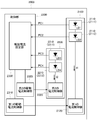
- FIG. 1 is a block diagram showing a configuration of an excitation light source 100 of an optical amplifier according to the first embodiment of the present invention.
- the excitation light source 100 of the optical amplifier includes a plurality of light emitting units 110 connected in series, a current control unit 120 that controls a drive current flowing through the plurality of light emitting units 110, and a control unit 130 that controls the current control unit 120.
- the light emitting unit 110 includes a light output monitoring unit.
- the control unit 130 controls the current control unit 120 based on each output of the light output monitoring unit.
- the present invention is not limited to this, and a configuration in which three or more light emitting units are connected in series may be employed. . Even in this case, only one current control unit 120 may be provided.
- the light emitting unit 110 may include a semiconductor laser (Laser Diode: LD), and the light output monitor unit may include a photodiode (Photodiode: PD).
- the photodiode outputs photocurrents PC1 and PC2 corresponding to the optical output of the semiconductor laser to the control unit 130, respectively.
- the control unit 130 determines a drive current set value that is a value of the drive current so that the sum of the photocurrents PC1 and PC2 is constant, and the current is set so that the drive current is substantially the same as the drive current set value.
- the control unit 120 may be configured to be controlled.
- the pumping light source 100 of the optical amplifier has a configuration in which a plurality of typically semiconductor lasers (LDs) are connected in series as a light emitting unit (for example, two in the case shown in FIG. 1). ).
- LDs typically semiconductor lasers
- the emission efficiencies (electro-optical conversion efficiencies) of the respective semiconductor lasers are substantially equal.
- the currents flowing through the plurality of semiconductor lasers are controlled so that the sum of the currents of the photodiodes (PDs) built in the semiconductor lasers for monitoring the rear light output of the semiconductor lasers is constant.
- the total sum of the optical outputs of the excitation light source 100 of the optical amplifier can be kept constant.
- the output of the optical amplifier can be kept constant over a long period of time.
- a method for controlling the excitation light source of the optical amplifier according to the present embodiment will be described.
- a drive current is supplied in series to a plurality of light emitting units. Then, a part of the light output of each of the plurality of light emitting units is detected, and the drive current of the light emitting unit is controlled based on the detected result.
- it is possible to obtain a photocurrent by detecting a part of the light outputs of the plurality of light emitting units, and to control the drive current so that the total sum of the photocurrents at this time is constant.
- the pumping light source of the optical amplifier of the present embodiment the pumping light output as the pumping light source is ensured over a long period of time even when the optical output is reduced in some of the plurality of semiconductor lasers. It is possible. Therefore, the output of the optical amplifier can be maintained for a long time.
- FIG. 2 is a block diagram showing a configuration of an excitation light source 2000 for an optical amplifier according to the second embodiment of the present invention.
- the pumping light source 2000 of the optical amplifier includes a first light source unit 2100, a second light source unit 2200 connected in parallel with the first light source unit 2100, and a control unit 2300.
- the first light source unit 2100 has a configuration in which a plurality of first light emitting units 2110 and first current control units 2120 each having a first light output monitor unit are connected in series.
- the second light source unit 2200 has a configuration in which a plurality of second light emitting units 2210 and second current control units 2220 each having a second light output monitor unit are connected in series.
- the first current control unit 2120 controls the first drive current I1 flowing through the first light emitting unit 2110
- the second current control unit 2220 performs the second drive current flowing through the second light emitting unit 2210. I2 is controlled.
- the control unit 2300 controls the first current control unit 2120 and the second current control unit 2220 based on the output of the first light output monitor unit and the output of the second light output monitor unit.
- FIG. 2 shows a case where the first light source unit 2100 and the second light source unit 2200 include two first light emitting units 2111, 2112, and second light emitting units 2211, 2122, respectively.
- the present invention is not limited to this, and a configuration in which three or more light emitting units are connected in series may be employed. Even in this case, each of the first light source unit 2100 and the second light source unit 2200 may include one first current control unit 2120 and one second current control unit 2220.
- the pumping light source 2000 of the optical amplifier of the present embodiment the number of current control units can be reduced as compared with the number of light emitting units.
- an excitation light source for an optical amplifier having a simple configuration can be obtained.
- the first light source unit 2100 and the second light source unit 2200 are connected in parallel, when one of the light emitting units fails and the circuit of one of the light source units is disconnected. Even if it exists, light output can be maintained by the other light source part. Therefore, according to the excitation light source 2000 of the optical amplifier of this embodiment, it is possible to realize further high reliability of the optical amplifier.
- each of the first light emitting unit 2110 and the second light emitting unit 2210 can be configured to include a semiconductor laser (LD1, LD2, LD3, and LD4 in FIG. 2).
- LD1, LD2, LD3, and LD4 in FIG. 2
- each of the first light output monitor unit and the second light output monitor unit may include a photodiode. These photodiodes respectively output photocurrents (PC1, PC2, PC3, PC4) corresponding to the optical output of the semiconductor laser.
- the control unit 2300 can be configured to control the first current control unit 2120 and the second current control unit 2220 so that the total sum of photocurrents (PC1 + PC2 + PC3 + PC4) is constant.
- the control unit 2300 can include a first drive current control unit 2310, a second drive current control unit 2320, and a drive current setting unit 2330.
- the drive current setting unit 2330 uses a first drive current set value that is the value of the first drive current and a value of the second drive current so that the total of the photocurrents (PC1 + PC2 + PC3 + PC4) is constant. A certain second drive current set value is determined.
- the first drive current control unit 2310 controls the first current control unit 2120 so that the first drive current I1 is substantially the same as the first drive current setting value.
- the second drive current control unit 2320 controls the second current control unit 2220 so that the second drive current I2 is substantially the same as the second drive current setting value.
- the drive current setting unit 2330 acquires photocurrents (PC1, PC2, PC3, PC4) corresponding to the optical output of each semiconductor laser from the photodiode as the optical output monitor unit of each semiconductor laser. Based on this photocurrent, it is determined whether the operating state of each semiconductor laser is a normal operation or a failure operation.
- the drive current setting unit 2330 increases at least one of the first drive current set value and the second drive current set value described above.
- the first drive current control unit 2310 (or the second drive current control unit 2320) determines the drive current set value after the first drive current I1 (or the second drive current I2) has increased.
- the first current control unit 2120 (or the second current control unit 2220) is controlled so as to be substantially the same.
- the total of the photocurrents (PC1 + PC2 + PC3 + PC4) corresponding to the optical output of each semiconductor laser (LD) is constant. Can be kept in. As a result, the excitation light output as the excitation light source can be kept constant.
- FIG. 3 is a diagram showing an example of control logic when a semiconductor laser (LD) serving as a light emitting unit fails, and shows a case where four semiconductor lasers (LD) are used.
- the vertical row in FIG. 3 is a classification based on the number (p) of semiconductor lasers in a failure operation state.
- Each horizontal column indicates the optical output of each semiconductor laser (LD), specifically, the classification for each photocurrent (PC) of each photodiode, and the drive currents I1 and I2 of each semiconductor laser (LD).
- the symbol “ ⁇ ” indicates the case where the operating state of the semiconductor laser is a normal operation
- the symbol “X” indicates the case where the operating state of the semiconductor laser is a failure operation.
- the control unit 2300 controls the drive currents (I1 and I2) flowing through each semiconductor laser (LD) based on a logical operation corresponding to the operating state of each semiconductor laser (LD). Thus, feedback control is performed so that the pumping light output, which is the sum of the light outputs of the respective semiconductor lasers, is constant.
- the drive current I1 flows through the semiconductor lasers LD1 and LD2, and the semiconductor lasers LD3 and LD4 flow.
- Each of the drive currents I2 is increased to 4/3 times.
- the light output from the semiconductor laser LD4 cannot be obtained, but the semiconductor lasers LD1 and LD2 and LD3 can obtain light outputs proportional to “(4/3) I”, respectively. Therefore, a value proportional to “4I” is obtained as the pumping light output that is the sum of the light outputs of the respective semiconductor lasers. That is, it becomes possible to ensure the same pumping light output as when three semiconductor lasers use four semiconductor lasers.
- the present invention is not limited to this, and only two of the four semiconductor lasers are used during the initial operation, and the remaining two semiconductors are used.
- the laser may be deactivated and used as a standby system.
- the drive current I1 flowing through the semiconductor lasers LD1 and LD2 can be set to zero, and the drive current I2 flowing through the semiconductor lasers LD3 and LD4 can be rated.
- the pumping light output can be made constant, it is possible to always ensure the output of the optical amplifier.
- a method for controlling the excitation light source of the optical amplifier according to the present embodiment will be described.
- a first drive current is supplied in series to the plurality of first light emitting units, and the second driving unit is connected in series to the plurality of second light emitting units.
- Supply drive current At this time, a part of the light output of the plurality of first light emitting units is detected to acquire the first photocurrent, and a part of the light output of the plurality of second light emitting units is detected to detect the second. Get the photocurrent.
- the first drive current and the second drive current are controlled so that the sum of the first photocurrent and the second photocurrent is constant.
- each operation state of the first light emitting unit and the second light emitting unit is a normal operation or a failure operation. If it is determined that a failure operation is included, at least one of the first drive current and the second drive current may be increased.
- one current control unit is provided for each light source unit even in a redundant configuration in which a plurality of light source units including a plurality of light emitting units are connected in parallel. It can be configured. Therefore, according to the present embodiment, it is possible to obtain an excitation light source for an optical amplifier having a simple configuration that realizes high reliability of the optical amplifier.
Landscapes
- Physics & Mathematics (AREA)
- Electromagnetism (AREA)
- Engineering & Computer Science (AREA)
- Optics & Photonics (AREA)
- Plasma & Fusion (AREA)
- Computer Networks & Wireless Communication (AREA)
- Signal Processing (AREA)
- Condensed Matter Physics & Semiconductors (AREA)
- General Physics & Mathematics (AREA)
- Lasers (AREA)
- Semiconductor Lasers (AREA)
Description
本発明は、光増幅器の励起用光源およびその制御方法に関し、特に、長期信頼性が要求される光増幅器の励起用光源およびその制御方法に関する。
光通信システムにおいては、光ファイバ中を伝播して減衰した光信号を増幅するために光増幅器が用いられる。このような光増幅器は、例えば光海底ケーブルシステムにおいては海底に設置された光中継器等で使用されるため、長期間にわたる高信頼性が要求される。
光通信システムでは光増幅器として、エルビウム(Er)等の希土類元素を光ファイバに添加し励起用光源によって励起する光ファイバ型の光増幅器が広く用いられている。この場合、光増幅器の長期信頼性を確保するためには、励起用光源に対しても長期間にわたる高信頼性が要求される。
このような励起用光源を用いた光増幅器の一例が特許文献1に記載されている。特許文献1に記載された関連する光増幅器は、駆動回路4aにより駆動される励起光源5a、駆動回路4bにより別途駆動される励起光源5b、光電気変換器11a、光電気変換器11b、電圧合成器12、比較器13、および基準電圧発生器9を有する。ここで、光電気変換器11aは、励起光源5aにより発生された励起光の一部を光電気変換し、光電気変換器11bは、励起光源5bにより発生された励起光の一部を光電気変換する。電圧合成器12は、光電気変換器11a、11bにより光電気変換された電圧信号を合成する。比較器13は、電圧合成器12から出力された電圧信号と基準電圧発生器9からの基準電圧とを比較し、その電圧信号が基準電圧一定となるような可変制御信号を駆動回路4bに出力する。
ここで、励起光源5aはその励起光出力にかかわらず、一定の駆動電流で駆動される。この励起光源5aが劣化してその励起光出力が低下すると、光合波された合波光が低下し、その結果、電圧合成器12からの電圧信号が低下する。すると、駆動回路4bは、電圧信号が予め設定された一定値になるまで励起光源5bの励起光出力を上げる。このようにして、励起光源5aが劣化しても希土類添加光ファイバ1に供給される励起光は一定に保たれ、安定した光増幅特性が得られる、としている。
また、特許文献2には、複数の励起光源、出力レベル検出手段、出力レベル制御手段、励起光レベル検出手段、励起光レベル制御手段、および光合波手段を有する光増幅器が記載されている。ここで、出力レベル検出手段は、光増幅器の出力光信号のレベルを検出する。出力レベル制御手段は、検出された出力光レベル信号に基づいて出力光レベルが安定化するように複数の励起光源のうちの一励起光源を制御する。励起光レベル検出手段は、一励起光源以外の励起光源が出力する励起光のレベルをそれぞれ検出する。励起光レベル制御手段は、検出された各励起光レベル信号に基づいて各励起光レベルが安定化するように各励起光源を制御する。光合波手段は、全ての励起光源が出力する励起光を合波して光増幅するための励起光を生成する。
このような構成とすることにより、特許文献2に記載された関連する光増幅器によれば、励起光源を複数有していても、簡単な構成で出力レベル制御を実現できる、としている。
上述したように、関連する光増幅器においては、光増幅器の信頼性を高めるために、複数の励起光源を用いた冗長構成を採用している。しかしながら、複数の励起光源を個別に制御することとしているので、冗長度を高めると、励起光源の構成が複雑になるという問題があった。
このように、関連する光増幅器においては、光増幅器の信頼性を高めると励起光源の構成が複雑になる、という問題があった。
本発明の目的は、上述した課題である、関連する光増幅器においては、光増幅器の信頼性を高めると励起光源の構成が複雑になる、という課題を解決する光増幅器の励起用光源およびその制御方法を提供することにある。
本発明の光増幅器の励起用光源は、直列に接続された複数の発光部と、複数の発光部を流れる駆動電流を制御する電流制御部と、電流制御部を制御する制御部、とを有し、発光部は光出力モニタ部をそれぞれ備え、制御部は、光出力モニタ部の各出力に基づいて電流制御部を制御する。
また、本発明の光増幅器の励起用光源は、第1の光出力モニタ部をそれぞれ備えた複数の第1の発光部と第1の電流制御部が直列に接続された第1の光源部と、第2の光出力モニタ部をそれぞれ備えた複数の第2の発光部と第2の電流制御部が直列に接続された第2の光源部と、第1の光出力モニタ部の出力と第2の光出力モニタ部の出力に基づいて、第1の電流制御部と第2の電流制御部を制御する制御部、とを有し、第1の光源部と第2の光源部は並列に接続され、第1の電流制御部は、第1の発光部を流れる第1の駆動電流を制御し、第2の電流制御部は、第2の発光部を流れる第2の駆動電流を制御する。
本発明の光増幅器の励起用光源の制御方法は、複数の発光部に直列に駆動電流を供給し、複数の発光部の光出力の一部をそれぞれ検知し、検知した結果に基づいて、駆動電流を制御する。
また、本発明の光増幅器の励起用光源の制御方法は、複数の第1の発光部に直列に第1の駆動電流を供給し、複数の第2の発光部に直列に第2の駆動電流を供給し、複数の第1の発光部の光出力の一部をそれぞれ検知して第1の光電流を取得し、複数の第2の発光部の光出力の一部をそれぞれ検知して第2の光電流を取得し、第1の光電流と第2の光電流の総和が一定となるように、第1の駆動電流と第2の駆動電流を制御する。
本発明の光増幅器の励起用光源およびその制御方法によれば、光増幅器の高信頼性を実現する簡易な構成の光増幅器の励起用光源が得られる。
以下に、図面を参照しながら、本発明の実施形態について説明する。
〔第1の実施形態〕
図1は、本発明の第1の実施形態に係る光増幅器の励起用光源100の構成を示すブロック図である。光増幅器の励起用光源100は、直列に接続された複数の発光部110、これらの複数の発光部110を流れる駆動電流を制御する電流制御部120、および電流制御部120を制御する制御部130を有する。ここで、発光部110は光出力モニタ部をそれぞれ備える。制御部130は、光出力モニタ部の各出力に基づいて電流制御部120を制御する。図1では、光増幅器の励起用光源100が2個の発光部111、112を備えた場合について示したが、これに限らず、3個以上の発光部が直列に接続された構成としてもよい。この場合でも電流制御部120は1個だけ備えればよい。
図1は、本発明の第1の実施形態に係る光増幅器の励起用光源100の構成を示すブロック図である。光増幅器の励起用光源100は、直列に接続された複数の発光部110、これらの複数の発光部110を流れる駆動電流を制御する電流制御部120、および電流制御部120を制御する制御部130を有する。ここで、発光部110は光出力モニタ部をそれぞれ備える。制御部130は、光出力モニタ部の各出力に基づいて電流制御部120を制御する。図1では、光増幅器の励起用光源100が2個の発光部111、112を備えた場合について示したが、これに限らず、3個以上の発光部が直列に接続された構成としてもよい。この場合でも電流制御部120は1個だけ備えればよい。
ここで、発光部110は半導体レーザ(Laser Diode:LD)を備え、光出力モニタ部はフォトダイオード(Photodiode:PD)を備えた構成とすることができる。フォトダイオードは半導体レーザの光出力に応じた光電流PC1、PC2をそれぞれ制御部130に出力する。そして制御部130は、光電流PC1とPC2の総和が一定となるように、駆動電流の値である駆動電流設定値を決定し、駆動電流がこの駆動電流設定値と略同一となるように電流制御部120を制御する構成とすることができる。
このように、本実施形態による光増幅器の励起用光源100は、発光部として複数の典型的には半導体レーザ(LD)を直列に接続した構成である(例えば、図1に示す場合は2個)。ここで、各半導体レーザの発光効率(電気-光変換効率)は略等しいことが望ましい。そして、半導体レーザの後方光出力モニタ用として半導体レーザに内蔵したフォトダイオード(PD)の電流の総和が一定となるように、複数の半導体レーザに流れる電流を制御する。これにより、個々の半導体レーザに何らかの障害が発生した場合であっても、光増幅器の励起用光源100の光出力の総和を一定に保つことができる。その結果、光増幅器の出力も長期間にわたり一定に維持することが可能となる。
次に、本実施形態による光増幅器の励起用光源の制御方法について説明する。本実施形態による光増幅器の励起用光源の制御方法においては、まず、複数の発光部に直列に駆動電流を供給する。そして、これらの複数の発光部の光出力の一部をそれぞれ検知し、検知した結果に基づいて、発光部の駆動電流を制御する。ここで、複数の発光部の光出力の一部を検知して光電流をそれぞれ取得し、このときの光電流の総和が一定となるように駆動電流を制御する構成とすることができる。
上述したように本実施形態によれば、複数の発光部110を有する冗長構成とした場合であっても、1個の電流制御部を備えた構成とすることができる。そのため、本実施形態によれば、光増幅器の高信頼性を実現する簡易な構成の光増幅器の励起用光源100が得られる。
また一般に、光増幅器の安定な出力を長期間にわたって維持するためには、励起用光源の光出力も長期間にわたって安定に保つことが必要である。しかし、励起用光源の発光部に用いられる半導体レーザ等は光学部品であるため、部品固有の障害モードにより、その光出力が低下する可能性がある。しかしながら本実施形態の光増幅器の励起用光源によれば、複数の半導体レーザの一部で光出力の低下が発生した場合であっても、励起用光源としての励起光出力を長期間にわたって確保することが可能である。そのため、光増幅器の出力を長期間にわたって維持することができる。
〔第2の実施形態〕
次に、本発明の第2の実施形態について説明する。図2は、本発明の第2の実施形態に係る光増幅器の励起用光源2000の構成を示すブロック図である。光増幅器の励起用光源2000は、第1の光源部2100、第1の光源部2100と並列に接続された第2の光源部2200、および制御部2300を有する。
次に、本発明の第2の実施形態について説明する。図2は、本発明の第2の実施形態に係る光増幅器の励起用光源2000の構成を示すブロック図である。光増幅器の励起用光源2000は、第1の光源部2100、第1の光源部2100と並列に接続された第2の光源部2200、および制御部2300を有する。
第1の光源部2100は、第1の光出力モニタ部をそれぞれ備えた複数の第1の発光部2110と第1の電流制御部2120が直列に接続された構成である。また、第2の光源部2200は、第2の光出力モニタ部をそれぞれ備えた複数の第2の発光部2210と第2の電流制御部2220が直列に接続された構成である。ここで、第1の電流制御部2120は第1の発光部2110を流れる第1の駆動電流I1を制御し、第2の電流制御部2220は第2の発光部2210を流れる第2の駆動電流I2を制御する。
制御部2300は、第1の光出力モニタ部の出力と第2の光出力モニタ部の出力に基づいて、第1の電流制御部2120と第2の電流制御部2220を制御する。
図2では、第1の光源部2100および第2の光源部2200は、それぞれ2個の第1の発光部2111、2112および第2の発光部2211、2212を備えた場合について示す。しかし、これに限らず、それぞれ3個以上の発光部が直列に接続された構成としてもよい。この場合であっても、第1の光源部2100および第2の光源部2200には、第1の電流制御部2120および第2の電流制御部2220をそれぞれ一個ずつ備えればよい。
このような構成としたことにより、本実施形態の光増幅器の励起用光源2000によれば、発光部の個数に比べて電流制御部の個数を削減することができるので、光増幅器の高信頼性を実現する簡易な構成の光増幅器の励起用光源が得られる。さらに、第1の光源部2100と第2の光源部2200が並列に接続された構成としているので、いずれかの発光部が故障して、一方の光源部の回路が切断状態となった場合であっても、他方の光源部により光出力を維持することができる。そのため本実施形態の光増幅器の励起用光源2000によれば、光増幅器のさらなる高信頼性を実現することができる。
ここで、第1の発光部2110および第2の発光部2210はそれぞれ半導体レーザ(図2中のLD1、LD2、LD3、LD4)を備えた構成とすることができる。ここで、各半導体レーザの発光効率(電気-光変換効率)は略等しいことが望ましい。また、第1の光出力モニタ部および第2の光出力モニタ部はそれぞれフォトダイオードを備えた構成とすることができる。これらのフォトダイオードは半導体レーザの光出力に応じた光電流(PC1、PC2、PC3、PC4)をそれぞれ出力する。そして制御部2300は光電流の総和(PC1+PC2+PC3+PC4)が一定となるように、第1の電流制御部2120と第2の電流制御部2220を制御する構成とすることができる。
次に、制御部2300の構成について、さらに詳細に説明する。制御部2300は、第1の駆動電流制御部2310、第2の駆動電流制御部2320、および駆動電流設定部2330を備えた構成とすることができる。
ここで、駆動電流設定部2330は、光電流の総和(PC1+PC2+PC3+PC4)が一定となるように、第1の駆動電流の値である第1の駆動電流設定値と、第2の駆動電流の値である第2の駆動電流設定値を決定する。
そして、第1の駆動電流制御部2310は、第1の駆動電流I1が第1の駆動電流設定値と略同一となるように第1の電流制御部2120を制御する。また、第2の駆動電流制御部2320は、第2の駆動電流I2が第2の駆動電流設定値と略同一となるように第2の電流制御部2220を制御する。
このような構成とすることにより、複数の半導体レーザ(LD)の一部で光出力の低下が発生した場合であっても、各半導体レーザ(LD)の光出力に応じた光電流の総和(PC1+PC2+PC3+PC4)は一定に保たれる。そのため、このような場合であっても、励起用光源としての励起光出力を一定に保持することが可能である。その結果、光増幅器の出力を長期間にわたって維持することができる。
次に、本実施形態による光増幅器の励起用光源2000の動作について説明する。駆動電流設定部2330は、各半導体レーザの光出力モニタ部としてのフォトダイオードから、各半導体レーザの光出力に応じた光電流(PC1、PC2、PC3、PC4)を取得する。そして、この光電流に基づいて各半導体レーザの動作状態が正常動作であるか故障動作であるかを判別する。
その結果、故障動作状態にある半導体レーザが存在すると判断した場合、駆動電流設定部2330は上述した第1の駆動電流設定値および第2の駆動電流設定値の少なくとも一方を増大する。このとき、第1の駆動電流制御部2310(または第2の駆動電流制御部2320)は、第1の駆動電流I1(または第2の駆動電流I2)が、増大した後の駆動電流設定値と略同一となるように第1の電流制御部2120(または第2の電流制御部2220)を制御する。
これにより、複数の半導体レーザ(LD)の一部が故障状態となり、光出力が低下した場合であっても、各半導体レーザ(LD)の光出力に応じた光電流の総和(PC1+PC2+PC3+PC4)を一定に保つことができる。その結果、励起用光源としての励起光出力を一定に保持することが可能となる。
続いて、本実施形態による光増幅器の励起用光源2000の動作について、図3を用いて具体的に説明する。
図3は、発光部としての半導体レーザ(LD)の故障時における制御論理の一例を示す図であり、4個の半導体レーザ(LD)を使用した場合について示す。図3の縦の行は、故障動作状態にある半導体レーザの個数(p)による分類である。また、横の各列は各半導体レーザ(LD)の光出力、具体的には各フォトダイオードの光電流(PC)毎の分類、および各半導体レーザ(LD)の駆動電流I1、I2を示す。同図中、記号「○」は半導体レーザの動作状態が正常動作である場合を、記号「×」は半導体レーザの動作状態が故障動作である場合をそれぞれ示す。
制御部2300は、それぞれの半導体レーザ(LD)の動作状態に応じた論理演算に基づいて、各半導体レーザ(LD)に流れる駆動電流(I1およびI2)を制御する。これにより、各半導体レーザの光出力の総和である励起光出力が一定となるようにフィードバック制御を行う。
4個の半導体レーザがいずれも正常動作している場合(図3の1行目)、駆動電流I1およびI2をそれぞれ「I」とすると、各半導体レーザの光出力の総和である励起光出力は「4I」に比例する値となる。
4個の半導体レーザのうち、例えば、半導体レーザLD4(PC4)のみが故障した場合(図3中の2行目)、半導体レーザLD1とLD2に流れる駆動電流I1、および半導体レーザLD3とLD4に流れる駆動電流I2をそれぞれ4/3倍にする。このとき、半導体レーザLD4からの光出力は得られないが、半導体レーザLD1とLD2、およびLD3からは「(4/3)I」に比例する光出力がそれぞれ得られる。したがって、各半導体レーザの光出力の総和である励起光出力としては、「4I」に比例する値が得られる。すなわち、3個の半導体レーザで4個の半導体レーザを用いたときと同じ励起光出力を確保することが可能となる。
なお、上述の説明では、4個の半導体レーザを同時に使用することとしたが、これに限らず、初期動作時は4個の半導体レーザのうち2個だけを使用し、残りの2個の半導体レーザは非動作とし、予備系として用いることとしてもよい。例えば、半導体レーザLD1が故障した場合には、半導体レーザLD1およびLD2を流れる駆動電流I1をゼロとし、半導体レーザLD3およびLD4に流れる駆動電流I2を定格動作させることができる。この場合にも、励起光出力を一定とすることができるので、光増幅器の出力を常に確保することが可能となる。
次に、本実施形態による光増幅器の励起用光源の制御方法について説明する。本実施形態による光増幅器の励起用光源の制御方法においては、まず、複数の第1の発光部に直列に第1の駆動電流を供給し、複数の第2の発光部に直列に第2の駆動電流を供給する。このとき、複数の第1の発光部の光出力の一部をそれぞれ検知して第1の光電流を取得し、複数の第2の発光部の光出力の一部をそれぞれ検知して第2の光電流を取得する。そして、第1の光電流と第2の光電流の総和が一定となるように、第1の駆動電流と第2の駆動電流を制御する。
また、第1の光電流と第2の光電流に基づいて、第1の発光部および第2の発光部のそれぞれの動作状態が正常動作であるか故障動作であるかを判別する。そして、故障動作が含まれると判断した場合は、第1の駆動電流および第2の駆動電流の少なくとも一方を増大させることとしてもよい。
上述したように本実施形態によれば、複数の発光部を備えた光源部を並列に複数個接続した冗長構成とした場合であっても、光源部ごとに1個の電流制御部を備えた構成とすることができる。そのため、本実施形態によれば、光増幅器の高信頼性を実現する簡易な構成の光増幅器の励起用光源が得られる。
本発明は上記実施形態に限定されることなく、特許請求の範囲に記載した発明の範囲内で、種々の変形が可能であり、それらも本発明の範囲内に含まれるものであることはいうまでもない。
この出願は、2012年8月28日に出願された日本出願特願2012-187590を基礎とする優先権を主張し、その開示の全てをここに取り込む。
100、2000 光増幅器の励起用光源
110 発光部
120 電流制御部
130 制御部
2100 第1の光源部
2110 第1の発光部
2120 第1の電流制御部
2200 第2の光源部
2210 第2の発光部
2220 第2の電流制御部
2300 制御部
2310 第1の駆動電流制御部
2320 第2の駆動電流制御部
2330 駆動電流設定部
110 発光部
120 電流制御部
130 制御部
2100 第1の光源部
2110 第1の発光部
2120 第1の電流制御部
2200 第2の光源部
2210 第2の発光部
2220 第2の電流制御部
2300 制御部
2310 第1の駆動電流制御部
2320 第2の駆動電流制御部
2330 駆動電流設定部
Claims (10)
- 直列に接続された複数の発光手段と、
前記複数の発光手段を流れる駆動電流を制御する電流制御手段と、
前記電流制御手段を制御する制御手段、とを有し、
前記発光手段は光出力モニタ手段をそれぞれ備え、
前記制御手段は、前記光出力モニタ手段の各出力に基づいて前記電流制御手段を制御する
光増幅器の励起用光源。 - 請求項1に記載した光増幅器の励起用光源において、
前記発光手段は半導体レーザを備え、
前記光出力モニタ手段はフォトダイオードを備え、
前記フォトダイオードは前記半導体レーザの光出力に応じた光電流をそれぞれ出力し、
前記制御手段は、前記光電流の総和が一定となるように、前記駆動電流の値である駆動電流設定値を決定し、前記駆動電流が前記駆動電流設定値と略同一となるように前記電流制御手段を制御する
光増幅器の励起用光源。 - 第1の光出力モニタ手段をそれぞれ備えた複数の第1の発光手段と第1の電流制御手段が直列に接続された第1の光源手段と、
第2の光出力モニタ手段をそれぞれ備えた複数の第2の発光手段と第2の電流制御手段が直列に接続された第2の光源手段と、
前記第1の光出力モニタ手段の出力と前記第2の光出力モニタ手段の出力に基づいて、前記第1の電流制御手段と前記第2の電流制御手段を制御する制御手段、とを有し、
前記第1の光源手段と前記第2の光源手段は並列に接続され、
前記第1の電流制御手段は、前記第1の発光手段を流れる第1の駆動電流を制御し、
前記第2の電流制御手段は、前記第2の発光手段を流れる第2の駆動電流を制御する
光増幅器の励起用光源。 - 請求項3に記載した光増幅器の励起用光源において、
前記第1の発光手段および第2の発光手段はそれぞれ半導体レーザを備え、
前記第1の光出力モニタ手段および前記第2の光出力モニタ手段はそれぞれフォトダイオードを備え、前記フォトダイオードは前記半導体レーザの光出力に応じた光電流をそれぞれ出力し、
前記制御手段は、前記光電流の総和が一定となるように、前記第1の電流制御手段と前記第2の電流制御手段を制御する
光増幅器の励起用光源。 - 請求項4に記載した光増幅器の励起用光源において、
前記制御手段は、駆動電流設定手段と、第1の駆動電流制御手段と、第2の駆動電流制御手段とを備え、
前記駆動電流設定手段は、前記光電流の総和が一定となるように、前記第1の駆動電流の値である第1の駆動電流設定値と、前記第2の駆動電流の値である第2の駆動電流設定値を決定し、
前記第1の駆動電流制御手段は、前記第1の駆動電流が前記第1の駆動電流設定値と略同一となるように前記第1の電流制御手段を制御し、
前記第2の駆動電流制御手段は、前記第2の駆動電流が前記第2の駆動電流設定値と略同一となるように前記第2の電流制御手段を制御する
光増幅器の励起用光源。 - 請求項5に記載した光増幅器の励起用光源において、
前記駆動電流設定手段は、前記光電流に基づいて各半導体レーザの動作状態が正常動作であるか故障動作であるかを判別し、
故障動作状態にある半導体レーザが存在すると判断した場合は、前記第1の駆動電流設定値および前記第2の駆動電流設定値の少なくとも一方を増大する
光増幅器の励起用光源。 - 複数の発光手段に直列に駆動電流を供給し、
前記複数の発光手段の光出力の一部をそれぞれ検知し、
前記検知した結果に基づいて、前記駆動電流を制御する
光増幅器の励起用光源の制御方法。 - 請求項7に記載した光増幅器の励起用光源の制御方法において、
前記複数の発光手段の光出力の一部を検知して光電流をそれぞれ取得し、
前記光電流の総和が一定となるように前記駆動電流を制御する
光増幅器の励起用光源の制御方法。 - 複数の第1の発光手段に直列に第1の駆動電流を供給し、
複数の第2の発光手段に直列に第2の駆動電流を供給し、
前記複数の第1の発光手段の光出力の一部をそれぞれ検知して第1の光電流を取得し、
前記複数の第2の発光手段の光出力の一部をそれぞれ検知して第2の光電流を取得し、
前記第1の光電流と前記第2の光電流の総和が一定となるように、前記第1の駆動電流と前記第2の駆動電流を制御する
光増幅器の励起用光源の制御方法。 - 請求項9に記載した光増幅器の励起用光源の制御方法において、
前記第1の光電流と前記第2の光電流に基づいて、前記第1の発光手段および前記第2の発光手段のそれぞれの動作状態が正常動作であるか故障動作であるかを判別し、
故障動作が含まれると判断した場合は、前記第1の駆動電流および前記第2の駆動電流の少なくとも一方を増大させる
光増幅器の励起用光源の制御方法。
Priority Applications (1)
| Application Number | Priority Date | Filing Date | Title |
|---|---|---|---|
| JP2014532776A JP6172151B2 (ja) | 2012-08-28 | 2013-08-26 | 光増幅器の励起用光源およびその制御方法 |
Applications Claiming Priority (2)
| Application Number | Priority Date | Filing Date | Title |
|---|---|---|---|
| JP2012187590 | 2012-08-28 | ||
| JP2012-187590 | 2012-08-28 |
Publications (1)
| Publication Number | Publication Date |
|---|---|
| WO2014034073A1 true WO2014034073A1 (ja) | 2014-03-06 |
Family
ID=50182910
Family Applications (1)
| Application Number | Title | Priority Date | Filing Date |
|---|---|---|---|
| PCT/JP2013/005004 Ceased WO2014034073A1 (ja) | 2012-08-28 | 2013-08-26 | 光増幅器の励起用光源およびその制御方法 |
Country Status (2)
| Country | Link |
|---|---|
| JP (1) | JP6172151B2 (ja) |
| WO (1) | WO2014034073A1 (ja) |
Cited By (1)
| Publication number | Priority date | Publication date | Assignee | Title |
|---|---|---|---|---|
| CN110383717A (zh) * | 2017-03-17 | 2019-10-25 | 日本电气株式会社 | 光海底线缆系统和光海底中继设备 |
Citations (9)
| Publication number | Priority date | Publication date | Assignee | Title |
|---|---|---|---|---|
| JPH043029A (ja) * | 1990-04-20 | 1992-01-08 | Fujitsu Ltd | 光増幅用ポンピング光源の駆動方法 |
| JPH0541552A (ja) * | 1991-07-30 | 1993-02-19 | Nec Corp | 切替機能を有する光フアイバ増幅器励起用レーザ駆動回路 |
| JPH05235445A (ja) * | 1992-02-19 | 1993-09-10 | Nippon Telegr & Teleph Corp <Ntt> | 光ファイバ増幅器 |
| JPH05268166A (ja) * | 1992-03-18 | 1993-10-15 | Kokusai Denshin Denwa Co Ltd <Kdd> | 光増幅中継回路 |
| JPH06204594A (ja) * | 1992-08-21 | 1994-07-22 | American Teleph & Telegr Co <Att> | 光増幅装置 |
| JPH1126852A (ja) * | 1997-06-25 | 1999-01-29 | Oerlikon Contraves Ag | 光導波路を用いて空間を基礎として量子光増幅器を動作させるための方法及び装置 |
| JP2000196184A (ja) * | 1998-12-28 | 2000-07-14 | Nec Corp | レ―ザダイオ―ドモジュ―ル |
| JP2012151313A (ja) * | 2011-01-19 | 2012-08-09 | Nikon Corp | ファイバ光増幅器 |
| WO2013121744A1 (ja) * | 2012-02-14 | 2013-08-22 | 日本電気株式会社 | 中継装置及び、それに用いる励起光供給装置並びに励起光供給方法 |
-
2013
- 2013-08-26 WO PCT/JP2013/005004 patent/WO2014034073A1/ja not_active Ceased
- 2013-08-26 JP JP2014532776A patent/JP6172151B2/ja active Active
Patent Citations (9)
| Publication number | Priority date | Publication date | Assignee | Title |
|---|---|---|---|---|
| JPH043029A (ja) * | 1990-04-20 | 1992-01-08 | Fujitsu Ltd | 光増幅用ポンピング光源の駆動方法 |
| JPH0541552A (ja) * | 1991-07-30 | 1993-02-19 | Nec Corp | 切替機能を有する光フアイバ増幅器励起用レーザ駆動回路 |
| JPH05235445A (ja) * | 1992-02-19 | 1993-09-10 | Nippon Telegr & Teleph Corp <Ntt> | 光ファイバ増幅器 |
| JPH05268166A (ja) * | 1992-03-18 | 1993-10-15 | Kokusai Denshin Denwa Co Ltd <Kdd> | 光増幅中継回路 |
| JPH06204594A (ja) * | 1992-08-21 | 1994-07-22 | American Teleph & Telegr Co <Att> | 光増幅装置 |
| JPH1126852A (ja) * | 1997-06-25 | 1999-01-29 | Oerlikon Contraves Ag | 光導波路を用いて空間を基礎として量子光増幅器を動作させるための方法及び装置 |
| JP2000196184A (ja) * | 1998-12-28 | 2000-07-14 | Nec Corp | レ―ザダイオ―ドモジュ―ル |
| JP2012151313A (ja) * | 2011-01-19 | 2012-08-09 | Nikon Corp | ファイバ光増幅器 |
| WO2013121744A1 (ja) * | 2012-02-14 | 2013-08-22 | 日本電気株式会社 | 中継装置及び、それに用いる励起光供給装置並びに励起光供給方法 |
Cited By (4)
| Publication number | Priority date | Publication date | Assignee | Title |
|---|---|---|---|---|
| CN110383717A (zh) * | 2017-03-17 | 2019-10-25 | 日本电气株式会社 | 光海底线缆系统和光海底中继设备 |
| EP3598668A4 (en) * | 2017-03-17 | 2020-03-18 | Nec Corporation | OPTICAL UNDERWATER CABLE SYSTEM AND OPTICAL UNDERWATER RELAY DEVICE |
| US11223427B2 (en) | 2017-03-17 | 2022-01-11 | Nec Corporation | Optical submarine cable system and optical submarine relay apparatus |
| CN110383717B (zh) * | 2017-03-17 | 2022-10-25 | 日本电气株式会社 | 光海底线缆系统和光海底中继设备 |
Also Published As
| Publication number | Publication date |
|---|---|
| JP6172151B2 (ja) | 2017-08-02 |
| JPWO2014034073A1 (ja) | 2016-08-08 |
Similar Documents
| Publication | Publication Date | Title |
|---|---|---|
| US9444219B2 (en) | Repeater, excitation light supply device used for the same, and excitation light supply method | |
| EP3113301B1 (en) | Fiber laser device and method for detecting abnormality thereof | |
| US9203518B2 (en) | Optical transmitter and waveform compensation method | |
| JPH1012954A (ja) | 光増幅器 | |
| US6798567B2 (en) | Method and apparatus for controlling power transients in an optical communication system | |
| EP3098911B1 (en) | Control method, control device, and light source device | |
| JP2009004903A (ja) | 光データリンク及び光出力制御方法 | |
| WO2018097075A1 (ja) | 光通信装置および光増幅用の励起光を供給する装置 | |
| JP6172151B2 (ja) | 光増幅器の励起用光源およびその制御方法 | |
| US20220102932A1 (en) | Optical amplification device and optical amplification method | |
| US9496676B2 (en) | Optical amplifier and control method thereof | |
| JP6210532B2 (ja) | レーザ装置 | |
| JP3923060B2 (ja) | 光増幅器 | |
| US20250309988A1 (en) | Power supply circuit, repeater, and power feeding method in repeater | |
| JP6273704B2 (ja) | 光中継器 | |
| JP6245364B2 (ja) | 半導体レーザ装置 | |
| JP6334222B2 (ja) | 送信装置、受信装置、光通信システム、送信方法および受信方法 | |
| JP2006128382A (ja) | 光増幅器 | |
| WO2018155405A1 (ja) | 光出力モジュールおよび発光制御方法 | |
| JP4773703B2 (ja) | 光増幅器 | |
| JP2002368693A (ja) | 光送信器 | |
| JP2019009395A (ja) | 光ファイバ増幅器および光ファイバ増幅システム | |
| JP2008306081A (ja) | Mmpldを使用した光増幅方法と光増幅器 | |
| WO2007134635A1 (en) | Optical amplifiers | |
| JP2009503835A (ja) | 二重ポンプパワー制御を有する双光増幅器 |
Legal Events
| Date | Code | Title | Description |
|---|---|---|---|
| 121 | Ep: the epo has been informed by wipo that ep was designated in this application |
Ref document number: 13832824 Country of ref document: EP Kind code of ref document: A1 |
|
| ENP | Entry into the national phase |
Ref document number: 2014532776 Country of ref document: JP Kind code of ref document: A |
|
| NENP | Non-entry into the national phase |
Ref country code: DE |
|
| 122 | Ep: pct application non-entry in european phase |
Ref document number: 13832824 Country of ref document: EP Kind code of ref document: A1 |