WO2014030660A1 - 電気接続箱 - Google Patents
電気接続箱 Download PDFInfo
- Publication number
- WO2014030660A1 WO2014030660A1 PCT/JP2013/072239 JP2013072239W WO2014030660A1 WO 2014030660 A1 WO2014030660 A1 WO 2014030660A1 JP 2013072239 W JP2013072239 W JP 2013072239W WO 2014030660 A1 WO2014030660 A1 WO 2014030660A1
- Authority
- WO
- WIPO (PCT)
- Prior art keywords
- bonder cap
- terminal
- cover
- low
- bonder
- Prior art date
Links
Images
Classifications
-
- H—ELECTRICITY
- H02—GENERATION; CONVERSION OR DISTRIBUTION OF ELECTRIC POWER
- H02G—INSTALLATION OF ELECTRIC CABLES OR LINES, OR OF COMBINED OPTICAL AND ELECTRIC CABLES OR LINES
- H02G3/00—Installations of electric cables or lines or protective tubing therefor in or on buildings, equivalent structures or vehicles
- H02G3/02—Details
- H02G3/08—Distribution boxes; Connection or junction boxes
- H02G3/16—Distribution boxes; Connection or junction boxes structurally associated with support for line-connecting terminals within the box
-
- H—ELECTRICITY
- H01—ELECTRIC ELEMENTS
- H01R—ELECTRICALLY-CONDUCTIVE CONNECTIONS; STRUCTURAL ASSOCIATIONS OF A PLURALITY OF MUTUALLY-INSULATED ELECTRICAL CONNECTING ELEMENTS; COUPLING DEVICES; CURRENT COLLECTORS
- H01R4/00—Electrically-conductive connections between two or more conductive members in direct contact, i.e. touching one another; Means for effecting or maintaining such contact; Electrically-conductive connections having two or more spaced connecting locations for conductors and using contact members penetrating insulation
- H01R4/22—End caps, i.e. of insulating or conductive material for covering or maintaining connections between wires entering the cap from the same end
Definitions
- the present invention relates to an electric junction box having a frame provided with a bonder cap housing portion and a terminal-equipped wire housing portion.
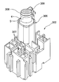
- FIG. 4 is a perspective view of a frame used in a conventional electric junction box, and is a perspective view showing a state in which the bonder cap is press-fitted and held in the bonder cap housing portion of the frame.
- FIG. 5 is a perspective view of only the frame shown in FIG.
- the frame 302 is made of synthetic resin, and has a bonder cap housing portion 306 in which the bonder cap 5 is press-fitted and held, and a terminal-attached wire housing portion 307 into which a terminal-attached electric wire is inserted. And a through hole 309 through which the binding band 308 is passed. 4 and 5, a part of the frame 302 is shown.
- the bonder cap housing portion 306 is formed in a bottomed cylindrical shape capable of housing the bonder cap 5.
- the bonder cap 5 is a member that covers the end portion of the wire bundle 4 and protects the portion where the core wires of each wire are electrically connected.
- the terminal-equipped electric wire accommodating portion 307 is formed in a cylindrical shape and is disposed adjacent to the bonder cap accommodating portion 306. Moreover, the edge part which comprises the insertion opening of the bonder cap accommodating part 306 protrudes rather than the edge part which comprises the insertion opening of the electric wire accommodating part 307 with a terminal.
- the through hole 309 is provided in the vicinity of the insertion opening of the bonder cap housing portion 306. As shown in FIG. 4, the binding band 308 passed through the through hole 309 is wound around the outer periphery of the wire bundle 4 to prevent the bonder cap 5 from dropping from the bonder cap housing portion 306.
- the first problem is that the edge portion constituting the insertion port of the bonder cap housing portion 306 protrudes beyond the edge portion constituting the insertion port of the terminal-attached wire housing portion 307. This is a problem that it is difficult to insert into the portion 307.
- the second problem is that since the through hole 309 is provided in the frame 302, the shape of the manufacturing mold of the frame 302 becomes complicated. In addition, since the binding band 308 is used to prevent the bonder cap 5 from falling off, there is a problem that the parts cost is increased and the number of assembling steps is increased.
- the inventor of the present application abolished the through hole 309 and the binding band 308, and instead pressed the bonder cap 5 with a cover attached to the frame 302, and removed the bonder cap 5. I found a way to prevent it. However, this method cannot solve the first problem.
- the first object of the present invention is to provide an electrical junction box that can prevent the bonder cap from falling off from the bonder cap housing portion without using a binding band, and the bonder cap can be bonded to a bonder without using a binding band. It is a second object to provide an electrical junction box that can be prevented from falling off from the cap housing portion and that can easily insert a terminal-attached electric wire into the terminal-attached electric wire housing portion.
- the invention described in claim 1 includes a frame and a cover attached to the frame, and the wires are covered with the ends of the wire bundles.
- the edge part constituting the insertion port of the bonder cap housing part has a low-profile part and a projection projecting from the low profile part
- the distance from the low-profile part to the cover is larger than the total length of the bonder cap in a state where the cover is attached to the frame.
- An electrical junction box characterized in that a distance from the most projecting portion of the projecting portion to the cover is smaller than the total length of the bonder cap, and the wire bundle is bent toward the low profile portion side
- the invention described in claim 2 is the invention described in claim 1, wherein the terminal-attached electric wire accommodating portion is adjacent to the low-profile portion, and A back part is formed in the same height as the edge which comprises the insertion port of the electric wire accommodating part with a terminal, It is characterized by the above-mentioned.
- an edge portion that constitutes an insertion port of the bonder cap housing portion is constituted by a low-profile portion and a protruding portion that protrudes from the low-profile portion, and the cover Is attached to the frame, the distance from the low-profile part to the cover is larger than the total length of the bonder cap, and the distance from the most protruding part of the protruding part to the cover is longer than the total length of the bonder cap.
- the elastic restoring force of the bent wire bundle acts and the bonder
- the cap is inclined to the protruding portion side opposite to the low-profile portion, and the bonder cap is prevented from falling off by being sandwiched between the protruding portion side wall and the cover. Therefore, it is possible to provide an electrical junction box that can prevent the bonder cap from falling off the bonder cap housing portion without using a binding band.
- the wire housing portion with a terminal is adjacent to the low profile portion, and the low profile portion constitutes an insertion port of the wire housing portion with the terminal. Therefore, it is possible to prevent the bonder cap from falling off from the bonder cap housing part without using a binding band, and to easily insert the terminal-attached electric wire into the terminal-attached electric wire container.
- An electrical junction box can be provided.
- FIG. 5 is a perspective view of only the frame shown in FIG. 4.
- an “electric connection box” according to an embodiment of the present invention will be described with reference to FIGS.
- the “electric connection box” is mounted on a vehicle and supplies power and transmits signals to an electronic device mounted on the vehicle.
- a junction block also referred to as a junction box
- a fuse block also referred to as a fuse box
- a relay block also referred to as a relay box
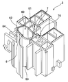
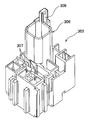
- the electrical junction box 1 has a synthetic resin frame 2 and a synthetic resin cover 3 attached to the frame 2 as shown in FIG.
- the frame 2 is provided with a bonder cap housing portion 6 into which the bonder cap 5 is press-fitted and held, and a plurality of terminal-attached wire housing portions 7 into which the electric wires with terminals are inserted.
- FIG. 1 shows a part of the frame 2.
- the bonder cap housing 6 is formed in a bottomed cylindrical shape capable of housing the bonder cap 5.
- reference numeral 64 denotes a peripheral wall constituting the bonder cap housing portion 6
- reference numeral 63 denotes a bottom wall
- reference numeral 60 denotes an insertion port.
- the edge part which comprises the insertion port 60 of the bonder cap accommodating part 6 has the low profile part 61 of the same height as the edge part which comprises the insertion slot 70 of the electric wire accommodating part 7 with a terminal, and this low profile part 61.
- a protruding portion 62 protruding. That is, while the edge part which comprises the insertion port 70 of the electric wire accommodating part 7 with a terminal is uniform height, the edge part which comprises the insertion port 60 of the bonder cap accommodating part 6 is slanting. .
- the bonder cap 5 is a synthetic resin member that covers the end of the wire bundle 4 and protects the portion where the core wires of each wire are electrically connected.
- Each electric wire is a covered electric wire, and the insulating coating is removed at the end thereof, and the core wire is exposed. Moreover, the core wires of each electric wire are electrically connected by welding or the like.
- the bonder cap 5 covers a portion where these core wires are electrically connected to each other and plays a role of waterproofing and insulation.
- the terminal-equipped wire accommodating portion 7 is formed in a cylindrical shape.
- the terminal-attached electric wire accommodating portion 7 that is disposed adjacent to the bonder cap accommodating portion 6 among the plurality of electric wire accommodating portions 7 with terminals is adjacent to the low-profile portion 61 of the bonder cap accommodating portion 6.
- the low-profile portion 61 of the bonder cap housing portion 6 is formed at the same height as the edge portion that constitutes the insertion port 70 of the terminal-attached wire housing portion 7 arranged adjacently.
- the edge part of all the electric wire accommodating parts 7 with a terminal is formed in uniform height, the electric wire accommodating part 7 with a terminal which is not adjacent to the bonder cap accommodating part 6 is the The edge portion may protrude from the low-profile portion 61.
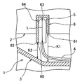
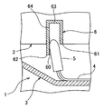
- the cover 3 is attached to the insertion ports 60 and 70 side of the bonder cap housing portion 6 and the terminal-attached wire housing portion 7 as shown in FIG. Further, the cover 3 and the frame 2 are such that the distance K1 from the low-profile portion 61 to the cover 3 is larger than the total length L of the bonder cap 5 with the cover 3 attached to the frame 2, and the protruding portion 62 protrudes the most.
- the distance K2 from the portion to the cover 3 is formed to be smaller than the total length L of the bonder cap 5.
- the wire bundle 4 positioned outside the bonder cap housing 6 is bent toward the low-profile portion 61 side.
- the elastic restoring force of the bent wire bundle 4 acts to bond the bonder.
- the cap 5 is inclined to the protruding portion 62 side opposite to the low-profile portion 61, and the bonder cap 5 is prevented from falling off by being sandwiched between the peripheral wall 64 and the cover 3 on the protruding portion 62 side. Therefore, it is possible to prevent the bonder cap 5 from dropping from the bonder cap housing portion 6 without using a binding band.
- the electric wire with terminal is used as a terminal. It can be easily inserted into the attached electric wire housing part 7.
Landscapes
- Engineering & Computer Science (AREA)
- Architecture (AREA)
- Civil Engineering (AREA)
- Structural Engineering (AREA)
- Connection Or Junction Boxes (AREA)
- Connector Housings Or Holding Contact Members (AREA)
- Connections Effected By Soldering, Adhesion, Or Permanent Deformation (AREA)
- Insertion, Bundling And Securing Of Wires For Electric Apparatuses (AREA)
Priority Applications (4)
| Application Number | Priority Date | Filing Date | Title |
|---|---|---|---|
| US14/420,446 US9203224B2 (en) | 2012-08-22 | 2013-08-21 | Electrical junction box |
| DE112013004137.5T DE112013004137B4 (de) | 2012-08-22 | 2013-08-21 | Elektrischer Verteiler |
| CN201380044478.8A CN104604062B (zh) | 2012-08-22 | 2013-08-21 | 电接线盒 |
| IN330KON2015 IN2015KN00330A (zh) | 2012-08-22 | 2013-08-21 |
Applications Claiming Priority (2)
| Application Number | Priority Date | Filing Date | Title |
|---|---|---|---|
| JP2012182963A JP5896416B2 (ja) | 2012-08-22 | 2012-08-22 | 電気接続箱 |
| JP2012-182963 | 2012-08-22 |
Publications (1)
| Publication Number | Publication Date |
|---|---|
| WO2014030660A1 true WO2014030660A1 (ja) | 2014-02-27 |
Family
ID=50149966
Family Applications (1)
| Application Number | Title | Priority Date | Filing Date |
|---|---|---|---|
| PCT/JP2013/072239 WO2014030660A1 (ja) | 2012-08-22 | 2013-08-21 | 電気接続箱 |
Country Status (6)
| Country | Link |
|---|---|
| US (1) | US9203224B2 (zh) |
| JP (1) | JP5896416B2 (zh) |
| CN (1) | CN104604062B (zh) |
| DE (1) | DE112013004137B4 (zh) |
| IN (1) | IN2015KN00330A (zh) |
| WO (1) | WO2014030660A1 (zh) |
Cited By (1)
| Publication number | Priority date | Publication date | Assignee | Title |
|---|---|---|---|---|
| US11427142B2 (en) * | 2019-11-27 | 2022-08-30 | Yazaki Corporation | Electrical connection box with bonder cap and shallow/deep bottom parts, and wire harness including same |
Families Citing this family (2)
| Publication number | Priority date | Publication date | Assignee | Title |
|---|---|---|---|---|
| JP6919599B2 (ja) * | 2018-03-05 | 2021-08-18 | 住友電装株式会社 | 電気接続箱 |
| JP6914905B2 (ja) | 2018-11-29 | 2021-08-04 | 矢崎総業株式会社 | ボンダーキャップの収容構造、電気接続箱、及びワイヤハーネス |
Citations (3)
| Publication number | Priority date | Publication date | Assignee | Title |
|---|---|---|---|---|
| JP2004088946A (ja) * | 2002-08-28 | 2004-03-18 | Yazaki Corp | 分割式接続ブロック |
| JP2010136570A (ja) * | 2008-12-08 | 2010-06-17 | Yazaki Corp | 電気接続箱 |
| JP2012085431A (ja) * | 2010-10-12 | 2012-04-26 | Yazaki Corp | 電気接続箱 |
Family Cites Families (10)
| Publication number | Priority date | Publication date | Assignee | Title |
|---|---|---|---|---|
| US5587556A (en) * | 1993-12-20 | 1996-12-24 | Yazaki Corporation | Protective casing for end connecting part of wire |
| JP3191906B2 (ja) * | 1995-07-03 | 2001-07-23 | 矢崎総業株式会社 | 電線接続部の収納構造 |
| US5747737A (en) * | 1996-02-16 | 1998-05-05 | Keith D. Waehner | Internally connected junction box |
| JP3324491B2 (ja) * | 1998-03-04 | 2002-09-17 | 住友電装株式会社 | 自動車用ワイヤハーネスの接続部の保持構造 |
| JP2000069647A (ja) * | 1998-08-19 | 2000-03-03 | Sumitomo Wiring Syst Ltd | 電気接続箱におけるワイヤハーネスの接続部の保持構造 |
| JP3356088B2 (ja) * | 1998-11-30 | 2002-12-09 | 住友電装株式会社 | 電気接続構造 |
| JP2001186630A (ja) * | 1999-12-24 | 2001-07-06 | Sumitomo Wiring Syst Ltd | 電気接続箱 |
| JP4218232B2 (ja) * | 2001-07-23 | 2009-02-04 | 住友電装株式会社 | ジャンクションボックス |
| JP2005269860A (ja) * | 2004-03-22 | 2005-09-29 | Yazaki Corp | 電気接続箱 |
| JP5067199B2 (ja) * | 2008-02-29 | 2012-11-07 | 住友電装株式会社 | 車載用の電気接続箱 |
-
2012
- 2012-08-22 JP JP2012182963A patent/JP5896416B2/ja active Active
-
2013
- 2013-08-21 US US14/420,446 patent/US9203224B2/en active Active
- 2013-08-21 WO PCT/JP2013/072239 patent/WO2014030660A1/ja active Application Filing
- 2013-08-21 DE DE112013004137.5T patent/DE112013004137B4/de active Active
- 2013-08-21 IN IN330KON2015 patent/IN2015KN00330A/en unknown
- 2013-08-21 CN CN201380044478.8A patent/CN104604062B/zh active Active
Patent Citations (3)
| Publication number | Priority date | Publication date | Assignee | Title |
|---|---|---|---|---|
| JP2004088946A (ja) * | 2002-08-28 | 2004-03-18 | Yazaki Corp | 分割式接続ブロック |
| JP2010136570A (ja) * | 2008-12-08 | 2010-06-17 | Yazaki Corp | 電気接続箱 |
| JP2012085431A (ja) * | 2010-10-12 | 2012-04-26 | Yazaki Corp | 電気接続箱 |
Cited By (1)
| Publication number | Priority date | Publication date | Assignee | Title |
|---|---|---|---|---|
| US11427142B2 (en) * | 2019-11-27 | 2022-08-30 | Yazaki Corporation | Electrical connection box with bonder cap and shallow/deep bottom parts, and wire harness including same |
Also Published As
| Publication number | Publication date |
|---|---|
| IN2015KN00330A (zh) | 2015-07-10 |
| US9203224B2 (en) | 2015-12-01 |
| CN104604062A (zh) | 2015-05-06 |
| JP2014042388A (ja) | 2014-03-06 |
| DE112013004137B4 (de) | 2023-06-15 |
| CN104604062B (zh) | 2017-02-22 |
| JP5896416B2 (ja) | 2016-03-30 |
| US20150236489A1 (en) | 2015-08-20 |
| DE112013004137T5 (de) | 2015-05-07 |
Similar Documents
| Publication | Publication Date | Title |
|---|---|---|
| JP5779010B2 (ja) | バスバモジュール構造体 | |
| WO2012108514A1 (ja) | バスバモジュール | |
| JP5567736B2 (ja) | リードフレームおよびリードフレームを有する接続ソケット | |
| JP5950301B2 (ja) | 電気接続箱 | |
| JP6914905B2 (ja) | ボンダーキャップの収容構造、電気接続箱、及びワイヤハーネス | |
| JP6448925B2 (ja) | コネクタ | |
| US9520255B2 (en) | Connection structure of electronic component and terminal metal fittings | |
| JP5215152B2 (ja) | 電気接続箱 | |
| WO2014030660A1 (ja) | 電気接続箱 | |
| JP2017123746A (ja) | プロテクタ及びプロテクタ付ワイヤーハーネス | |
| CN103855661A (zh) | 电接线盒 | |
| JP2011234427A (ja) | 電気接続箱 | |
| WO2014192943A1 (ja) | バスバモジュール及び電源装置 | |
| JP2011223777A (ja) | ボルトブロックの取付構造 | |
| JP6622034B2 (ja) | 電気接続箱、及び、ワイヤハーネス | |
| JP5541597B2 (ja) | 太陽電池モジュール用端子ボックスの出力ケーブル固定構造 | |
| JP2016116335A (ja) | ジャンクションボックスおよびワイヤハーネス | |
| JP2014230427A (ja) | ボンダーの保持構造 | |
| JP4309791B2 (ja) | ヒューズホルダ及びヒューズユニット | |
| JP5829543B2 (ja) | 布線板 | |
| JP2019068634A (ja) | 電気接続箱及びワイヤハーネス | |
| JP7290421B2 (ja) | 電気接続箱の製造方法 | |
| WO2014192808A1 (ja) | ヒューズユニット | |
| JP3123120U (ja) | リード線付きヒューズ | |
| JP6110120B2 (ja) | 電線用プロテクタ |
Legal Events
| Date | Code | Title | Description |
|---|---|---|---|
| 121 | Ep: the epo has been informed by wipo that ep was designated in this application |
Ref document number: 13830853 Country of ref document: EP Kind code of ref document: A1 |
|
| WWE | Wipo information: entry into national phase |
Ref document number: 14420446 Country of ref document: US |
|
| WWE | Wipo information: entry into national phase |
Ref document number: 112013004137 Country of ref document: DE Ref document number: 1120130041375 Country of ref document: DE |
|
| 122 | Ep: pct application non-entry in european phase |
Ref document number: 13830853 Country of ref document: EP Kind code of ref document: A1 |