WO2014030646A1 - 空気入りタイヤ - Google Patents
空気入りタイヤ Download PDFInfo
- Publication number
- WO2014030646A1 WO2014030646A1 PCT/JP2013/072198 JP2013072198W WO2014030646A1 WO 2014030646 A1 WO2014030646 A1 WO 2014030646A1 JP 2013072198 W JP2013072198 W JP 2013072198W WO 2014030646 A1 WO2014030646 A1 WO 2014030646A1
- Authority
- WO
- WIPO (PCT)
- Prior art keywords
- bead
- tire
- wire
- bead wire
- rubber
- Prior art date
- Legal status (The legal status is an assumption and is not a legal conclusion. Google has not performed a legal analysis and makes no representation as to the accuracy of the status listed.)
- Ceased
Links
Images

Classifications
-
- B—PERFORMING OPERATIONS; TRANSPORTING
- B60—VEHICLES IN GENERAL
- B60C—VEHICLE TYRES; TYRE INFLATION; TYRE CHANGING; CONNECTING VALVES TO INFLATABLE ELASTIC BODIES IN GENERAL; DEVICES OR ARRANGEMENTS RELATED TO TYRES
- B60C15/00—Tyre beads, e.g. ply turn-up or overlap
- B60C15/04—Bead cores
-
- D—TEXTILES; PAPER
- D07—ROPES; CABLES OTHER THAN ELECTRIC
- D07B—ROPES OR CABLES IN GENERAL
- D07B1/00—Constructional features of ropes or cables
- D07B1/06—Ropes or cables built-up from metal wires, e.g. of section wires around a hemp core
- D07B1/0606—Reinforcing cords for rubber or plastic articles
- D07B1/0666—Reinforcing cords for rubber or plastic articles the wires being characterised by an anti-corrosive or adhesion promoting coating
-
- B—PERFORMING OPERATIONS; TRANSPORTING
- B60—VEHICLES IN GENERAL
- B60C—VEHICLE TYRES; TYRE INFLATION; TYRE CHANGING; CONNECTING VALVES TO INFLATABLE ELASTIC BODIES IN GENERAL; DEVICES OR ARRANGEMENTS RELATED TO TYRES
- B60C9/00—Reinforcements or ply arrangement of pneumatic tyres
- B60C9/0007—Reinforcements made of metallic elements, e.g. cords, yarns, filaments or fibres made from metal
- B60C2009/0014—Surface treatments of steel cords
-
- B—PERFORMING OPERATIONS; TRANSPORTING
- B60—VEHICLES IN GENERAL
- B60C—VEHICLE TYRES; TYRE INFLATION; TYRE CHANGING; CONNECTING VALVES TO INFLATABLE ELASTIC BODIES IN GENERAL; DEVICES OR ARRANGEMENTS RELATED TO TYRES
- B60C15/00—Tyre beads, e.g. ply turn-up or overlap
- B60C15/04—Bead cores
- B60C2015/042—Bead cores characterised by the material of the core, e.g. alloy
-
- D—TEXTILES; PAPER
- D07—ROPES; CABLES OTHER THAN ELECTRIC
- D07B—ROPES OR CABLES IN GENERAL
- D07B2501/00—Application field
- D07B2501/20—Application field related to ropes or cables
- D07B2501/2046—Tyre cords
- D07B2501/2053—Tyre cords for wheel rim attachment
Definitions
- the present invention relates to a pneumatic tire using a bead wire on which a coumarone resin film has been formed.
- the present invention relates to a pneumatic tire excellent in durability by improving adhesion between a rubber composition in a sulfur state and a bead wire to prevent rubber curling.
- a bead wire made of high carbon steel having excellent strength and rigidity is used as a reinforcing material in a bead portion of a tire of an automobile or the like. Adhesion between the bead wire (reinforcing material) and the rubber is important. If the two are not firmly adhered, for example, heat or moisture generated during running of the tire causes a decrease in the adhesive strength with the rubber, The rubber may peel off and cause tire failure.
- Patent Document 1 and Patent Document 2 describe that a coumarone resin or the like is applied to a bead wire surface for the purpose of preventing surface deterioration.
- Patent Document 1 discloses a stranded wire in which a plurality of steel wires are twisted together, and the surface of a rubber-filled steel cord in which an internal space of the stranded wire is filled with an unvulcanized rubber composition, A material coated with a resin film made of resin or resorcin resin is described.
- Patent Document 2 describes a tire bead wire obtained by surface coating a resin made of a novolac type phenol resin and / or a novolac type resorcin resin.
- the present invention has been made in view of such problems, and an object thereof is to provide a pneumatic tire that can be manufactured in a favorable working environment by defining the melting point and the coating amount of the coumarone resin within a predetermined range. It is another object of the present invention to provide a pneumatic tire excellent in durability by preventing adhesion of a rubber by increasing adhesion between an unvulcanized rubber composition and a bead wire.
- the present invention is a pneumatic tire using a bead wire on which a coumarone resin film is formed, and the coumaron resin constituting the coumarone resin film has a melting point of 75 ° C. or higher at a heating temperature (° C.).
- the present invention provides a pneumatic tire characterized in that the amount of coumarone resin applied to the bead wire is 0.04 to 0.08 g / kg of wire / mm of wire.
- the heating temperature is the heating temperature of the bead wire when producing the bead core, preferably 90 ° C. to 110 ° C., more preferably 95 ° C. to 105 ° C.
- the melting point of the coumarone resin is preferably 75 ° C. or higher and the heating temperature (° C.) ⁇ 5 ° C. or lower.
- the melting point and the coating amount of the coumarone resin to be applied to the bead wire within a predetermined range, it is possible to manufacture a pneumatic tire in a favorable working environment without applying gasoline. Furthermore, the adhesion between the unvulcanized rubber composition and the bead wire can be increased to prevent rubber curling and a pneumatic tire having excellent durability can be provided.
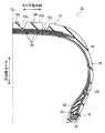
- FIG. 1 It is sectional drawing which shows the cross-sectional shape of the right half with respect to the meridian CL of the pneumatic tire which concerns on embodiment of this invention.
- A is typical sectional drawing which shows a bead core
- (b) is a typical perspective view which shows the bead wire used for a bead core.
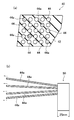
- (A) is typical sectional drawing which shows the bead core used for a bead pull-out test
- (b) is typical side view which shows the test sample of the bead core used for a bead pull-out test.
- FIG. 1 is a cross-sectional view showing a right half cross-sectional shape with respect to a meridian CL of a pneumatic tire according to an embodiment of the present invention.
- a pneumatic tire (hereinafter simply referred to as a tire) 10 illustrated in FIG. 1 includes a tread portion 12, a sidewall portion 14, and a bead portion 16 as main components.
- the tire left half not shown in FIG. 1 has the same configuration.
- the tire width direction refers to a direction parallel to a tire rotation axis (not shown), and the tire radial direction is orthogonal to the rotation axis.
- the tire circumferential direction refers to the direction of rotation with the rotation axis as the axis serving as the center of rotation.
- a carcass layer 18 is mounted between the pair of left and right bead portions 16, and both end portions in the tire width direction are wound around the bead core 20 from the inside of the tire 10 to the outside.
- the bead core 20 is configured by winding a single bead wire (not shown) in an annular shape so that a plurality of circumferential portions thereof are arranged in the tire width direction and overlap each other in the tire radial direction.
- a bead filler 26 made of a rubber composition is disposed on the outer peripheral side of the bead core 20.
- the bead core 20 and the bead filler 26 are enclosed by the main body portion and the folded portion of the carcass layer 18.
- a side reinforcing layer 22 is provided along the outside of the folded end portion of the carcass layer 18 in a region extending from the sidewall portion 14 to the bead portion 16.
- Four belt layers 24 are arranged on the outer peripheral side of the carcass layer 18 in the tread portion 12.
- These belt layers 24 include a plurality of reinforcing cords inclined with respect to the tire circumferential direction, and are arranged so that the reinforcing cords cross each other between the layers.
- the inclination angle of the reinforcing cord with respect to the tire circumferential direction is set in a range of 10 ° to 40 °, for example.
- the tread portion 12 is provided with a land portion 12b constituting a tread surface 12a outside the tire and a tread groove 12c formed in the tread surface 12a.
- the land portion 12b is partitioned by the tread groove 12c.
- the tread groove 12c has a main groove formed continuously in the tire circumferential direction and a plurality of lug grooves (not shown) extending in the tire width direction.
- a tread pattern is formed on the tread surface 12a by the tread groove 12c and the land portion 12b.
- the carcass layer 18 extends in the tire width direction from a portion corresponding to the tread portion 12 to a bead portion 16 through a portion corresponding to the shoulder portion and the sidewall portion 14 to form a tire skeleton.
- the carcass layer 18 has a configuration in which reinforcing cords are arranged in one direction at regular intervals, for example, in the tire width direction, and covered with cord coating rubber.
- the carcass layer 18 is folded back from the tire inner side to the tire outer side by a pair of left and right bead cores 20 and has an end portion in the region of the sidewall portion 14, and includes a main body portion and a folded portion with the bead core 20 as a boundary. ing.
- the rubber component used for the cord coating rubber of the carcass layer 18 is one or more kinds selected from natural rubber (NR), styrene-butadiene rubber (SBR), butadiene rubber (BR), and isoprene rubber (IR).
- NR natural rubber
- SBR styrene-butadiene rubber
- BR butadiene rubber
- IR isoprene rubber
- the rubber is preferably used.
- These rubbers were also end-modified with functional groups containing elements such as nitrogen, oxygen, fluorine, chlorine, silicon, phosphorus, or sulfur, such as amine, amide, hydroxyl, ester, ketone, siloxy, or alkylsilyl. Or those end-modified with epoxy can be used.
- Examples of the carbon black to be blended with these rubber components include an iodine adsorption amount of 20 to 100 (g / kg), preferably 20 to 50 (g / kg), and a DBP absorption amount of 50 to 135 (cm 3 / kg). 100 g), preferably 50 ⁇ 100 (cm 3 / 100g ), and CTAB adsorption specific surface area of 30 ⁇ 90 (m 2 / g ), preferably those which are 30 ⁇ 45 (m 2 / g ) is used .
- the amount of sulfur to be used is, for example, 1.5 to 4.0 parts by mass, preferably 2.0 to 3.0 parts by mass with respect to 100 parts by mass of rubber.
- the bead portion 16 is provided with a bead core 20 that functions to fold the carcass layer 18 and fix the tire 10 to the wheel, and a bead filler 26 so as to contact the bead core 20. Therefore, the bead core 20 and the bead filler 26 are sandwiched between the main body portion and the folded portion of the carcass layer 18.
- a side reinforcing layer 22 including a reinforcing cord that is inclined with respect to the tire circumferential direction is embedded in the bead portion 16.
- the side reinforcing layer 22 is configured by arranging reinforcing cords made of steel cords in a direction inclined with respect to the tire circumferential direction at regular intervals and covering them with a cord coating rubber.
- an organic fiber cord made of polyester, nylon, aromatic polyamide or the like is used in addition to the steel cord.
- the side reinforcement layer 22 can reinforce the side surface of the tire 10, that is, the bead portion 16 and / or the sidewall portion 14, the side reinforcement layer 22 is provided on all or only a part of the bead portion 16 and / or the sidewall portion 14. It may be a thing and the position of an edge part is not limited.
- the end portion of the side reinforcing layer 22 may be extended to a region in contact with the belt layer 24 of the shoulder portion, and may be provided for all of the bead portion 16 and the sidewall portion 14, or only the bead portion 16, Alternatively, it may be provided only for the side wall part 14, or may be provided by being divided into a plurality of parts, for example, divided into a bead part 16 and a side wall part 14.
- a conventionally known steel cord is used as the reinforcing cord of the side reinforcing layer 22, it is preferable to dispose the side reinforcing layer 22 between the bead filler 26 and the folded portion of the carcass layer 18, and the organic fiber cord
- the belt layer 24 is a reinforcing layer that is attached in the tire circumferential direction and reinforces the carcass layer 18.
- the belt layer 24 is provided in a portion corresponding to the tread portion 12.
- the belt layer 24 is not limited to the steel cord being a reinforcing cord, and a steel belt may be applied to only one of them, and at least one of them may be polyester, nylon, aromatic polyamide, or the like. It is good also as a conventionally well-known reinforcement cord which consists of an organic fiber cord etc. which consist of.
- a belt auxiliary reinforcing layer for reinforcing the belt layer 24 may be disposed on the uppermost layer of the belt layer 24 in the tire circumferential direction.
- a reinforcing cord for example, an organic fiber cord is spirally arranged in the tire circumferential direction, and these organic fiber cords are covered with a cord coating rubber.
- the belt auxiliary reinforcing layer may be, for example, a so-called full cover that covers the belt layer 24 from end to end in the tire width direction, or a so-called edge cover that covers only the end of the belt layer 24. . Furthermore, the belt auxiliary reinforcing layer may have a configuration in which a plurality of full covers are stacked, or may have a configuration in which an edge cover and a full cover are combined.
- the organic fiber cord for example, nylon 66 (polyhexamethylene adipamide) fiber, aramid fiber, composite fiber composed of aramid fiber and nylon 66 fiber (aramid / nylon 66 hybrid cord), PEN fiber POK (aliphatic polyketone) fiber, heat-resistant PET fiber, rayon fiber and the like are used.
- nylon 66 polyhexamethylene adipamide
- aramid fiber composite fiber composed of aramid fiber and nylon 66 fiber (aramid / nylon 66 hybrid cord)
- PEN fiber POK aliphatic polyketone
- FIG. 2A is a schematic cross-sectional view showing a bead core
- FIG. 2B is a schematic perspective view showing a bead wire used for the bead core.
- the bead core 20 is composed of a rubber composition 30 (insulation rubber) and a bead wire 32, and the bead wire 32 is covered with the rubber composition 30.
- the lower left end in FIG. 2A is a bead toe 20a.
- the bead core 20 is formed using a bead wire 32 having a coumarone resin film 34 formed on the surface 32a, as shown in FIG.
- this bead wire 32 the general thing used for a tire can be used.
- the coumarone resin film 34 as will be described in detail later, the melting point of the coumarone resin and the coating amount of the coumarone resin on the bead wire 32 are defined.
- the bead core 20 can be formed, for example, by heating the bead wire 32 having the coumarone resin film 34 formed on the surface 32a to a predetermined heating temperature and coating the bead wire 32 with the rubber composition 30 in an unvulcanized state. it can.
- the melting point of the coumarone resin and the coating amount of the coumarone resin on the bead wire 32 are defined for the coumarone resin film 34.
- the bead insulation includes covering the bead wires 32 with the unvulcanized rubber composition 30 one by one.
- the method for heating the bead wire 32 is not particularly limited.
- a method of heating the bead wire 32 by energizing the bead wire 32 (hereinafter referred to as an energizing heating method), a method of heating using hot air, and heating by electromagnetic induction.
- an energizing heating method a method of heating using hot air
- heating by electromagnetic induction a method of heating using hot air
- heating by electromagnetic induction There are ways to do this.
- the melting point of the coumarone resin is 75 ° C. or more and the heating temperature (° C.) or less, preferably the melting point is 75 ° C. or more and the heating temperature (° C.) ⁇ 5 ° C. or less.
- the heating temperature (° C.) ⁇ 5 ° C. is a temperature 5 ° C. lower than the heating temperature.
- the heating temperature is the heating temperature of the bead wire 32 when the bead core 20 is produced.
- the heating temperature is, for example, 90 ° C. to 110 ° C., preferably 95 ° C. to 105 ° C.
- Coumarone resin is a polymer of C 8 H 6 O and C 9 H.
- Coumarone resin is generally commercially available with a melting point of 40 ° C to 120 ° C. It is known that the coumarone resin can change the melting point by changing the molecular weight or the degree of polymerization.
- the melting point of the coumarone resin when the melting point of the coumarone resin is less than 75 ° C., the rust preventive property of the bead wire 32 is lowered due to the small molecular weight, and the adhesion between the rubber composition 30 and the bead wire 32 is lowered.
- the melting point of the coumarone resin exceeds the heating temperature, the coumarone resin is difficult to dissolve, and it becomes difficult to cover the bead wire 32 with the unvulcanized rubber composition 30.
- the heating temperature is less than 90 ° C., the initial reaction of adhesion does not occur and the adhesion to rubber is inferior.
- the heating temperature exceeds 110 ° C., the rubber is burned and it becomes difficult to cover the bead wire 32.
- the application amount of the coumarone resin to the bead wire 32 is 0.04 to 0.08 g / kg of wire / mm of wire.
- the coating amount of the coumarone resin is less than 0.04 g / kg of wire / mm of wire, the rust preventive property of the bead wire 32 is reduced, that is, moisture and oxygen are easily transmitted. Adhesiveness decreases.
- the application amount of the coumarone resin exceeds 0.08 g / kg of wire / mm of wire, the coumarone resin becomes difficult to dissolve, and the rubber coating of the bead wire 32 with the unvulcanized rubber composition 30 becomes difficult.
- a method for forming the coumarone resin film 34 on the surface 32a of the bead wire 32 is not particularly limited.
- a method of forming the resin film by bringing the surface 32a of the bead wire 32 into contact with a cotton yarn or a cloth structure impregnated with a resin solution. Is used.
- the resin solution when the resin is dissolved in a solvent and impregnated into a cotton yarn or a cloth structure as a resin solution and brought into contact with the bead wire 32, the resin solution can be uniformly applied to the surface 32a of the bead wire 32, and the solvent after the application By volatilizing, the uniform coumarone resin film 34 can be formed on the surface 32a of the bead wire 32 with only the resin having no thickness unevenness.
- the string structure as a supply path for the resin solution to the cloth structure.
- preferred solvents for the resin are, for example, xylene, toluene, ethanol, acetone, butanol and the like.
- the application amount of the coumarone resin can be adjusted by the concentration of the resin solution, the winding method of the cotton yarn or the cloth structure, or the like.
- the adhesion between the bead wire 32 and the unvulcanized rubber composition 30 is improved without using gasoline,
- the bead wire 32 can be made excellent in rubber curling resistance.
- the durability of the bead core 20 can be improved, and as a result, the tire 10 having excellent durability can be obtained.
- the tire 10 since no gasoline is used, the tire 10 can be manufactured in a favorable working environment.
- the present invention is basically configured as described above. As mentioned above, although the pneumatic tire of this invention was demonstrated in detail, this invention is not limited to the said embodiment, Of course, in the range which does not deviate from the main point of this invention, you may make various improvement or a change. is there.
- a bead core 40 shown in FIG. 3 (a) was prepared using the bead wires of Conventional Examples 1 and 2, Examples 1 and 2 and Comparative Examples 1 to 4 having the configuration shown in Table 1 below. A tire was produced.
- the bead core 40 shown in FIG. 3A has the same basic configuration as the bead core 20 shown in FIG.
- the rubber composition 42 mainly contains the following substances.
- Substances mainly contained in the rubber composition 42 include NR, SBR, CB, CALCIUM CARBONATE, aluminum silicate, aromatic oil, gum rosin, O, O'-dibenzamide diphenyl disulfide, WAX, cobalt naphthenate, salicylic acid, PVI, stearic acid, zinc oxide, DZ-G and sulfur.
- the bead wires 44 and 44a have a diameter of 1.20 mm.
- the bead wire 44 and the bead wire 44a are the same, and the bead wire 44a is pulled out in a bead pull-out test described later. For this reason, the bead wire 44 and the bead wire 44a are not particularly distinguished from each other except for the explanation regarding the bead pull-out test.
- the bead core 40 five bead wires 44 (one) were arranged in parallel, and five layers were stacked to make a total of 25 turns.
- the bead wire 44 was subjected to wet heat degradation in a constant temperature and humidity chamber at a temperature of 30 ° C. and 86% RH (relative humidity) for 30 days. Then, the bead core 40 was produced using the bead wire 44, and two tires having a tire size of 215 / 65R16 were produced using the bead core 40.
- NG was applied to gasoline and “Good” was not applied.
- rubber curling resistance a coumarone resin film was formed on the bead wire 44, and then an unvulcanized rubber composition was coated, and the state of the coated rubber was visually evaluated.
- the coated rubber without a pinhole or other defective part was designated as “Good”, and the coated rubber having a defective part such as a pinhole was designated as “NG”.
- the bead pull-out test was done about two produced tires, and it evaluated as follows.
- a test sample 50 having an embedding length of 25 mm was cut out from two bead cores 40 per tire as shown in FIG.
- each bead wire 44a equivalent to the four bead wires 44a of the bead core 40 shown to Fig.3 (a) was pulled out as shown in FIG.3 (b).
- the adhesion rate of the rubber adhering to the bead wire 44a was visually evaluated.
- Example 1 As shown in Table 1 above, in Examples 1 and 2, good results were obtained in all of the working environment, rubber curling resistance, and tire adhesion.
- Conventional Example 1 has a poor working environment because gasoline is applied.
- Conventional Example 2 since no coumarone resin is applied, the rust prevention property of the bead wire is insufficient and the tire adhesion is poor.
- Comparative Example 1 since the melting point of the coumarone resin is low, the rust prevention property of the bead wire is insufficient, and the tire adhesion is poor.
- Comparative Example 2 since the melting point of the coumarone resin exceeds the heating temperature (95 ° C.), the coumarone resin remains undissolved in the bead wire, and the rubber curling resistance is poor.
- Comparative Example 3 since the application amount of coumarone resin is small, the rust prevention property of the bead wire is insufficient, and the tire adhesion is poor. In Comparative Example 4, since the application amount of coumarone resin is large, the coumarone resin remains undissolved in the bead wire, and the rubber curling resistance is poor.
Landscapes
- Engineering & Computer Science (AREA)
- Mechanical Engineering (AREA)
- Tires In General (AREA)
- Ropes Or Cables (AREA)
Description
本発明は、クマロン樹脂膜が形成されたビードワイヤを使用した空気入りタイヤに関し、特に、クマロン樹脂の融点および塗布量を所定の範囲に規定することにより、良好な作業環境で製造できるとともに、未加硫状態のゴム組成物とビードワイヤの密着性を高めてゴム禿げを防止することにより耐久性が優れた空気入りタイヤに関する。
現在、自動車等のタイヤのビード部には補強材として強度および剛性に優れる高炭素鋼からなるビードワイヤが用いられている。ビードワイヤ(補強材)とゴムとの接着は重要であり、両者が強固に接着されないと、例えば、タイヤ走行時に発生する熱または水分等により、ゴムとの接着力の低下を引き起し、ビードワイヤとゴムとが剥離し、タイヤ故障の原因につながることがある。
そこで、従来、ビードインシュレーション時には、未加硫状態のゴム組成物とビードワイヤの密着性を高めてゴム禿げを防止するため、ビードワイヤ表面にガソリンを塗布し、被覆した未加硫状態のゴム組成物の表面を溶かしビードワイヤとの密着性を高めている。
さらには、ビードワイヤ表面を約95℃に加熱して、インシュレーション時に未加硫状態のゴム組成物とビードワイヤとを初期接着させ、密着性を高めることが行われていた。
一方、防錆を目的に、クマロン樹脂をビードワイヤ表面に塗布し、その上にガソリンを塗布した後、インシュレーションしているものもある。
表面劣化防止を目的に、クマロン樹脂等をビードワイヤ表面に塗布することは、特許文献1および特許文献2に記載されている。
さらには、ビードワイヤ表面を約95℃に加熱して、インシュレーション時に未加硫状態のゴム組成物とビードワイヤとを初期接着させ、密着性を高めることが行われていた。
一方、防錆を目的に、クマロン樹脂をビードワイヤ表面に塗布し、その上にガソリンを塗布した後、インシュレーションしているものもある。
表面劣化防止を目的に、クマロン樹脂等をビードワイヤ表面に塗布することは、特許文献1および特許文献2に記載されている。
具体的には、特許文献1には、複数本のスチールワイヤが撚り合わされた撚線であって、撚線の内部空隙に未加硫ゴム組成物を充填したゴム入りスチールコードの表面に、クマロン樹脂またはレゾルシン樹脂からなる樹脂膜を被覆したものが記載されている。
また、特許文献2には、ノボラック型フェノール樹脂および/またはノボラック型レゾルシン樹脂からなる樹脂を表面コーティングしてなるタイヤ用ビードワイヤが記載されている。
また、特許文献2には、ノボラック型フェノール樹脂および/またはノボラック型レゾルシン樹脂からなる樹脂を表面コーティングしてなるタイヤ用ビードワイヤが記載されている。
上述のように、未加硫状態のゴム組成物とビードワイヤの密着性を高めてゴム禿げを防止するためにガソリンを塗布することは、作業環境を悪化させるために好ましくない。
クマロン樹脂をビードワイヤ表面に塗布した後、ビードワイヤ表面を加熱することにより、未加硫状態のゴム組成物とビードワイヤとの密着性を高めてゴム禿げ性を防止することがなされているが、クマロン樹脂の溶け残りが発生し、ゴム禿げを起こしやすいという問題点がある。
クマロン樹脂をビードワイヤ表面に塗布した後、ビードワイヤ表面を加熱することにより、未加硫状態のゴム組成物とビードワイヤとの密着性を高めてゴム禿げ性を防止することがなされているが、クマロン樹脂の溶け残りが発生し、ゴム禿げを起こしやすいという問題点がある。
本発明はかかる問題点に鑑みてなされたものであり、クマロン樹脂の融点および塗布量を所定の範囲に規定することにより、良好な作業環境で製造できる空気入りタイヤを提供することを目的とする。
さらには、未加硫状態のゴム組成物とビードワイヤの密着性を高めてゴム禿げを防止し、耐久性が優れた空気入りタイヤを提供することを目的とする。
さらには、未加硫状態のゴム組成物とビードワイヤの密着性を高めてゴム禿げを防止し、耐久性が優れた空気入りタイヤを提供することを目的とする。
上記目的を達成するために、本発明は、クマロン樹脂膜が形成されたビードワイヤを使用した空気入りタイヤであって、クマロン樹脂膜を構成するクマロン樹脂は、融点が75℃以上加熱温度(℃)以下であり、クマロン樹脂のビードワイヤへの塗布量が0.04~0.08g/ワイヤkg/ワイヤmmであることを特徴とする空気入りタイヤを提供するものである。
加熱温度は、ビードコアを作製する際のビードワイヤの加熱温度のことであり、90℃~110℃であることが好ましく、より好ましくは95℃~105℃である。
なお、クマロン樹脂の融点は、75℃以上加熱温度(℃)-5℃以下であることが好ましい。
加熱温度は、ビードコアを作製する際のビードワイヤの加熱温度のことであり、90℃~110℃であることが好ましく、より好ましくは95℃~105℃である。
なお、クマロン樹脂の融点は、75℃以上加熱温度(℃)-5℃以下であることが好ましい。
本発明によれば、ビードワイヤに塗布するクマロン樹脂の融点および塗布量を所定の範囲に規定することにより、ガソリンの塗布を不要とし、良好な作業環境で空気入りタイヤを製造することができる。さらには、未加硫状態のゴム組成物とビードワイヤの密着性を高めてゴム禿げを防止することができ、耐久性が優れた空気入りタイヤを提供することができる。
以下に、添付の図面に示す好適実施形態に基づいて、本発明の空気入りタイヤを詳細に説明する。
図1は、本発明の実施形態に係る空気入りタイヤの子午線CLに対して右半分の断面形状を示す断面図である。
図1は、本発明の実施形態に係る空気入りタイヤの子午線CLに対して右半分の断面形状を示す断面図である。
図1に示す空気入りタイヤ(以下、単にタイヤという)10は、トレッド部12と、サイドウォール部14と、ビード部16とを主な構成部分として有する。図1中で示されていないタイヤ左半分についても、同様の構成を有する。
なお、以下の説明において、図1中に矢印で示すように、タイヤ幅方向とは、タイヤの回転軸(図示せず)と平行な方向をいい、タイヤ径方向とは、回転軸と直交する方向をいう。また、タイヤ周方向とは、回転軸を回転の中心となる軸として回転する方向をいう。
タイヤ10では、左右1対のビード部16間にはカーカス層18が装架され、そのタイヤ幅方向の両端部がそれぞれビードコア20の周りにタイヤ10内側から外側へ巻き上げられている。
なお、以下の説明において、図1中に矢印で示すように、タイヤ幅方向とは、タイヤの回転軸(図示せず)と平行な方向をいい、タイヤ径方向とは、回転軸と直交する方向をいう。また、タイヤ周方向とは、回転軸を回転の中心となる軸として回転する方向をいう。
タイヤ10では、左右1対のビード部16間にはカーカス層18が装架され、そのタイヤ幅方向の両端部がそれぞれビードコア20の周りにタイヤ10内側から外側へ巻き上げられている。
ビードコア20は、単一のビードワイヤ(図示せず)をその周回部分がタイヤ幅方向に複数本並びかつタイヤ径方向に複数層重なるように環状に巻き回すことで構成されている。ビードコア20の外周側にはゴム組成物からなるビードフィラー26が配置されている。そして、ビードコア20およびビードフィラー26はカーカス層18の本体部分と折り返し部分により包み込まれている。
また、サイドウォール部14からビード部16に亘る領域にはカーカス層18の折り返し端部の外側に沿ってサイド補強層22が設けられている。トレッド部12におけるカーカス層18の外周側には4層のベルト層24が配置されている。
これらベルト層24はタイヤ周方向に対して傾斜する複数本の補強コードを含み、かつ層間で補強コードが互いに交差するように配置されている。ベルト層24において、補強コードのタイヤ周方向に対する傾斜角度は、例えば、10°~40°の範囲に設定されている。
また、サイドウォール部14からビード部16に亘る領域にはカーカス層18の折り返し端部の外側に沿ってサイド補強層22が設けられている。トレッド部12におけるカーカス層18の外周側には4層のベルト層24が配置されている。
これらベルト層24はタイヤ周方向に対して傾斜する複数本の補強コードを含み、かつ層間で補強コードが互いに交差するように配置されている。ベルト層24において、補強コードのタイヤ周方向に対する傾斜角度は、例えば、10°~40°の範囲に設定されている。
トレッド部12には、タイヤ外側のトレッド面12aを構成する陸部12bと、トレッド面12aに形成されるトレッド溝12cとが設けられ、陸部12bは、トレッド溝12cによって区画される。トレッド溝12cは、タイヤ周方向に連続して形成される主溝とタイヤ幅方向に延在する複数のラグ溝(図示せず)を有する。トレッド面12aには、トレッド溝12cと陸部12bとによりトレッドパターンが形成される。
カーカス層18は、タイヤ幅方向に、トレッド部12に対応する部分から、ショルダー部およびサイドウォール部14に対応する部分を経てビード部16まで延在してタイヤの骨格をなすものである。
カーカス層18は、補強コードを一定間隔で一方向に向かって、例えば、タイヤ幅方向に向かって配列し、コードコーティングゴムで被覆した構成である。カーカス層18は、左右一対のビードコア20にタイヤ内側からタイヤ外側に折り返され、サイドウォール部14の領域で端部を成しており、ビードコア20を境とする本体部と折り返し部とから構成されている。
カーカス層18は、補強コードを一定間隔で一方向に向かって、例えば、タイヤ幅方向に向かって配列し、コードコーティングゴムで被覆した構成である。カーカス層18は、左右一対のビードコア20にタイヤ内側からタイヤ外側に折り返され、サイドウォール部14の領域で端部を成しており、ビードコア20を境とする本体部と折り返し部とから構成されている。
カーカス層18のコードコーティングゴムに使用されるゴム成分としては、天然ゴム(NR)、スチレン-ブタジエンゴム(SBR)、ブタジエンゴム(BR)およびイソプレンゴム(IR)から選ばれた1種類または複数種類のゴムが好ましく用いられる。また、これらのゴムを窒素、酸素、フッ素、塩素、ケイ素、リン、または硫黄等の元素を含む官能基、例えば、アミン、アミド、ヒドロキシル、エステル、ケトン、シロキシ、若しくはアルキルシリル等により末端変性したもの、またはエポキシにより末端変性したものを用いることができる。
これらゴム成分に配合するカーボンブラックとしては、例えば、ヨウ素吸着量が20~100(g/kg)、好ましくは20~50(g/kg)であり、DBP吸収量が50~135(cm3/100g)、好ましくは50~100(cm3/100g)であり、かつCTAB吸着比表面積が30~90(m2/g)、好ましくは30~45(m2/g)であるものが用いられる。
また、使用する硫黄の量は、例えば、ゴム100質量部に対して1.5~4.0質量部であり、好ましくは2.0~3.0質量部である。
これらゴム成分に配合するカーボンブラックとしては、例えば、ヨウ素吸着量が20~100(g/kg)、好ましくは20~50(g/kg)であり、DBP吸収量が50~135(cm3/100g)、好ましくは50~100(cm3/100g)であり、かつCTAB吸着比表面積が30~90(m2/g)、好ましくは30~45(m2/g)であるものが用いられる。
また、使用する硫黄の量は、例えば、ゴム100質量部に対して1.5~4.0質量部であり、好ましくは2.0~3.0質量部である。
ビード部16には、カーカス層18を折り返し、タイヤ10をホイールに固定するために機能するビードコア20と、ビードコア20に接するようにビードフィラー26が設けられている。そのため、ビードコア20およびビードフィラー26は、カーカス層18の本体部と折り返し部とで挟み込まれている。
また、ビード部16には、タイヤ周方向に対して傾斜する補強コードを含むサイド補強層22が埋設されている。
サイド補強層22は、スチールコードからなる補強コードを一定間隔でタイヤ周方向に対して傾斜した方向に向かって配列し、コードコーティングゴムで被覆して構成されている。このサイド補強層22の補強コードは、スチールコード以外にも、例えば、ポリエステル、ナイロンまたは芳香族ポリアミド等からなる有機繊維コード等が用いられる。
サイド補強層22は、スチールコードからなる補強コードを一定間隔でタイヤ周方向に対して傾斜した方向に向かって配列し、コードコーティングゴムで被覆して構成されている。このサイド補強層22の補強コードは、スチールコード以外にも、例えば、ポリエステル、ナイロンまたは芳香族ポリアミド等からなる有機繊維コード等が用いられる。
サイド補強層22は、タイヤ10の側面、すなわち、ビード部16および/またはサイドウォール部14の補強を行うことができれば、ビード部16および/またはサイドウォール部14の全部または一部のみに設けられるものであってもよく、端部の位置も、限定されるものではない。例えば、サイド補強層22の端部をショルダー部のベルト層24と接する領域まで延在させて、ビード部16およびサイドウォール部14の全部に対して設けられても良いし、ビード部16のみ、またはサイドウォール部14のみに対して設けられても良いし、例えば、ビード部16とサイドウォール部14とに分割する等、複数に分割して設けられていても良い。
さらに、サイド補強層22を設ける領域を補強コードの種類に応じて変えても良い。例えば、サイド補強層22の補強コードとして、従来公知のスチールコードを用いる場合には、ビードフィラー26とカーカス層18の折り返し部との間にサイド補強層22を配置するのが好ましく、有機繊維コードを用いる場合には、ビードコア20およびビードフィラー26を包み込むようにサイド補強層22を配置するのが好ましい。
さらに、サイド補強層22を設ける領域を補強コードの種類に応じて変えても良い。例えば、サイド補強層22の補強コードとして、従来公知のスチールコードを用いる場合には、ビードフィラー26とカーカス層18の折り返し部との間にサイド補強層22を配置するのが好ましく、有機繊維コードを用いる場合には、ビードコア20およびビードフィラー26を包み込むようにサイド補強層22を配置するのが好ましい。
ベルト層24は、タイヤ周方向に貼り付けられ、カーカス層18を補強するための補強層である。このベルト層24は、トレッド部12に対応する部分に設けられている。
ベルト層24は、いずれも補強コードがスチールコードであることに限定されるものではなく、いずれか一方のみにスチールベルトを適用しても良いし、少なくとも一方を、ポリエステル、ナイロン、芳香族ポリアミド等からなる有機繊維コード等からなる従来公知の補強コードとしても良い。
ベルト層24は、いずれも補強コードがスチールコードであることに限定されるものではなく、いずれか一方のみにスチールベルトを適用しても良いし、少なくとも一方を、ポリエステル、ナイロン、芳香族ポリアミド等からなる有機繊維コード等からなる従来公知の補強コードとしても良い。
タイヤ10には、ベルト層24の最上層上に、ベルト層24の補強を行うベルト補助補強層がタイヤ周方向に配置されていてもよい。このベルト補助補強層は、補強コードとして、例えば、有機繊維コードが、タイヤ周方向に螺旋状に配置されており、これらの有機繊維コードがコードコーティングゴムで被覆して構成されている。
なお、ベルト補助補強層は、例えば、ベルト層24をタイヤ幅方向に端から端まで覆う、いわゆるフルカバーと呼ばれるものでも、ベルト層24の端部のみを覆う、いわゆるエッジカバーと呼ばれるものでもよい。さらには、ベルト補助補強層は、フルカバーを複数積層した構成でもよく、エッジカバーと、フルカバーとを組み合わせた構成でもよい。
ベルト補助補強層において、有機繊維コードとして、例えば、ナイロン66(ポリヘキサメチレンアジパミド)繊維、アラミド繊維、アラミド繊維とナイロン66繊維とからなる複合繊維(アラミド/ナイロン66ハイブリッドコード)、PEN繊維、POK(脂肪族ポリケトン)繊維、耐熱PET繊維、およびレーヨン繊維等が用いられる。
次に、ビード部16のビードコア20について説明する。
図2(a)は、ビードコアを示す模式的断面図であり、(b)は、ビードコアに使用されるビードワイヤを示す模式的斜視図である。
図2(a)に示すように、ビードコア20は、ゴム組成物30(インシュレーションゴム)とビードワイヤ32とで構成されており、ビードワイヤ32は、ゴム組成物30により被覆されている。図2(a)においては、図2(a)中左下の端がビードトゥ20aである。
図2(a)は、ビードコアを示す模式的断面図であり、(b)は、ビードコアに使用されるビードワイヤを示す模式的斜視図である。
図2(a)に示すように、ビードコア20は、ゴム組成物30(インシュレーションゴム)とビードワイヤ32とで構成されており、ビードワイヤ32は、ゴム組成物30により被覆されている。図2(a)においては、図2(a)中左下の端がビードトゥ20aである。
ビードコア20の形成には、図2(b)に示すように、クマロン樹脂膜34が表面32aに形成されたビードワイヤ32を用いる。このビードワイヤ32としては、タイヤに使用される一般的なものを用いることができる。クマロン樹脂膜34においては、後に詳細に説明するが、クマロン樹脂の融点およびクマロン樹脂のビードワイヤ32に対する塗布量が規定されている。
ビードコア20は、例えば、クマロン樹脂膜34が表面32aに形成されたビードワイヤ32を、所定の加熱温度に加熱し、ビードワイヤ32を未加硫状態のゴム組成物30で被覆することにより形成することができる。
本発明においては、クマロン樹脂膜34についてクマロン樹脂の融点およびクマロン樹脂のビードワイヤ32に対する塗布量を規定している。これにより、ビードコア20を作製するために、ビードワイヤ32を所定の加熱温度に加熱してビードワイヤ32を未加硫状態のゴム組成物30で被覆する際、クマロン樹脂膜34は、未加硫状態のゴム組成物30に吸収されてビードワイヤ32の表面32aには残らず、ビードワイヤ32と未加硫状態のゴム組成物30とは良好な密着性が得られるため、ビードワイヤ32と未加硫状態のゴム組成物30との界面にピンホール等の欠損部分が形成されることもない。すなわち、耐ゴム禿げ性が良好である。
ビードワイヤ32を未加硫状態のゴム組成物30で被覆することを、ビードインシュレーションという。ビードインシュレーションには、ビードワイヤ32を1本ずつ未加硫状態のゴム組成物30で被覆することも含まれる。
本発明においては、クマロン樹脂膜34についてクマロン樹脂の融点およびクマロン樹脂のビードワイヤ32に対する塗布量を規定している。これにより、ビードコア20を作製するために、ビードワイヤ32を所定の加熱温度に加熱してビードワイヤ32を未加硫状態のゴム組成物30で被覆する際、クマロン樹脂膜34は、未加硫状態のゴム組成物30に吸収されてビードワイヤ32の表面32aには残らず、ビードワイヤ32と未加硫状態のゴム組成物30とは良好な密着性が得られるため、ビードワイヤ32と未加硫状態のゴム組成物30との界面にピンホール等の欠損部分が形成されることもない。すなわち、耐ゴム禿げ性が良好である。
ビードワイヤ32を未加硫状態のゴム組成物30で被覆することを、ビードインシュレーションという。ビードインシュレーションには、ビードワイヤ32を1本ずつ未加硫状態のゴム組成物30で被覆することも含まれる。
なお、ビードワイヤ32の加熱方法は、特に限定されるものではなく、例えば、ビードワイヤ32に通電して加熱する方法(以下、通電加熱方法という)、熱風を用いて加熱する方法、および電磁誘導により加熱する方法等がある。
このように、本発明では、ビードコア20の形成時にガソリンを塗布する必要がなくなり、作業環境を改善することができる。
このように、本発明では、ビードコア20の形成時にガソリンを塗布する必要がなくなり、作業環境を改善することができる。
また、クマロン樹脂の融点が75℃以上加熱温度(℃)以下であり、好ましくは融点が75℃以上加熱温度(℃)-5℃以下である。なお、加熱温度(℃)-5℃とは、加熱温度よりも5℃低い温度のことである。
加熱温度とは、ビードコア20を作製する際のビードワイヤ32の加熱温度のことである。加熱温度は、例えば、90℃~110℃であり、好ましくは95℃~105℃である。
クマロン樹脂とは、C8H6OとC9Hの重合体である。クマロン樹脂は、一般的に、融点は40℃~120℃のものが市販されている。クマロン樹脂は、分子量または重合度を変えることにより、融点が変えられることが知られている。
加熱温度とは、ビードコア20を作製する際のビードワイヤ32の加熱温度のことである。加熱温度は、例えば、90℃~110℃であり、好ましくは95℃~105℃である。
クマロン樹脂とは、C8H6OとC9Hの重合体である。クマロン樹脂は、一般的に、融点は40℃~120℃のものが市販されている。クマロン樹脂は、分子量または重合度を変えることにより、融点が変えられることが知られている。
本発明において、クマロン樹脂の融点が75℃未満では、分子量が小さいことによってビードワイヤ32の防錆性が低下し、ゴム組成物30とビードワイヤ32との接着性が低下する。
一方、クマロン樹脂の融点が加熱温度を超えると、クマロン樹脂が溶けにくくなり、未加硫状態のゴム組成物30によるビードワイヤ32のゴム被覆が困難になる。
加熱温度が90℃未満では、接着の初期反応が起こらずゴムとの密着性が劣る。また、加熱温度が110℃を超えると、ゴムが焼けてビードワイヤ32の被覆が困難になる。
一方、クマロン樹脂の融点が加熱温度を超えると、クマロン樹脂が溶けにくくなり、未加硫状態のゴム組成物30によるビードワイヤ32のゴム被覆が困難になる。
加熱温度が90℃未満では、接着の初期反応が起こらずゴムとの密着性が劣る。また、加熱温度が110℃を超えると、ゴムが焼けてビードワイヤ32の被覆が困難になる。
クマロン樹脂のビードワイヤ32に対する塗布量は、0.04~0.08g/ワイヤkg/ワイヤmmである。
クマロン樹脂の塗布量が0.04g/ワイヤkg/ワイヤmm未満では、ビードワイヤ32の防錆性の低下により、すなわち、水分および酸素が透過し易くなることにより、ゴム組成物30とビードワイヤ32との接着性が低下する。
一方、クマロン樹脂の塗布量が0.08g/ワイヤkg/ワイヤmmを超えると、クマロン樹脂が溶けにくくなり、未加硫状態のゴム組成物30によるビードワイヤ32のゴム被覆が困難になる。
クマロン樹脂の塗布量が0.04g/ワイヤkg/ワイヤmm未満では、ビードワイヤ32の防錆性の低下により、すなわち、水分および酸素が透過し易くなることにより、ゴム組成物30とビードワイヤ32との接着性が低下する。
一方、クマロン樹脂の塗布量が0.08g/ワイヤkg/ワイヤmmを超えると、クマロン樹脂が溶けにくくなり、未加硫状態のゴム組成物30によるビードワイヤ32のゴム被覆が困難になる。
ビードワイヤ32の表面32aにクマロン樹脂膜34を形成する方法は特に限定されないが、例えば、樹脂溶液を含浸させた綿糸または布構造物等にビードワイヤ32の表面32aを接触させて樹脂膜を形成する方法が用いられる。すなわち、樹脂を溶剤に溶かして樹脂溶液として、綿糸または布構造物等に含浸させ、ビードワイヤ32を接触させると、樹脂溶液をビードワイヤ32の表面32aに均一に塗布することができ、かつ塗布後に溶剤を揮発させることでビードワイヤ32の表面32aに樹脂のみを厚みむらのない均一なクマロン樹脂膜34を形成することができる。このとき、紐構造物を布構造物に対する樹脂溶液の供給路として用いることが好ましい。この樹脂膜の形成方法において、樹脂の好ましい溶剤としては、例えば、キシレン、トルエン、エタノール、アセトン、およびブタノール等である。
本発明において、上記クマロン樹脂の塗布量は、樹脂溶液の濃度、綿糸または布構造物等の巻き付け方等によって調整することができる。
本発明において、上記クマロン樹脂の塗布量は、樹脂溶液の濃度、綿糸または布構造物等の巻き付け方等によって調整することができる。
本発明においては、クマロン樹脂の融点および塗布量を所定の範囲に規定することにより、ガソリンを用いることなく、ビードワイヤ32と未加硫状態のゴム組成物30との密着性を良好とし、更にはビードワイヤ32の耐ゴム禿げ性に優れたものとすることができる。このため、ビードコア20の耐久性を向上させることができ、ひいては耐久性が優れたタイヤ10を得ることができる。
また、上述のように、本発明ではガソリンを用いることがないため、良好な作業環境でタイヤ10を製造することができる。
また、上述のように、本発明ではガソリンを用いることがないため、良好な作業環境でタイヤ10を製造することができる。
本発明は、基本的に以上のように構成されるものである。以上、本発明の空気入りタイヤについて詳細に説明したが、本発明は上記実施形態に限定されず、本発明の主旨を逸脱しない範囲において、種々の改良または変更をしてもよいのはもちろんである。
本発明の空気入りタイヤについて、具体的に説明する。
本実施例においては、下記表1に示す構成の従来例1、2、実施例1、2および比較例1~4のビードワイヤを用いて、図3(a)に示すビードコア40を作製し、その後、タイヤを作製した。なお、図3(a)に示すビードコア40は、図2(a)に示すビードコア20と基本的な構成は同じである。
本実施例においては、下記表1に示す構成の従来例1、2、実施例1、2および比較例1~4のビードワイヤを用いて、図3(a)に示すビードコア40を作製し、その後、タイヤを作製した。なお、図3(a)に示すビードコア40は、図2(a)に示すビードコア20と基本的な構成は同じである。
各従来例1、2、実施例1、2および比較例1~4について、作業環境、耐ゴム禿げ性およびタイヤ接着性を評価した。作業環境、耐ゴム禿げ性およびタイヤ接着性の結果を下記表1に示す。
ビードコア40においては、ゴム組成物42は、主に以下の物質を含んでいる。ゴム組成物42に主に含まれる物質としては、NR、SBR、CB、CALCIUM CARBONATE、ケイ酸アルミニウム、アロマ系オイル、ガムロジン、O,O’-ジベンズアミドジフェニルジスルフィド、WAX、ナフテン酸コバルト、サリチル酸、PVI、ステアリン酸、酸化亜鉛、DZ-Gおよび硫黄である。
また、ビードワイヤ44、44aには直径が1.20mmのものを用いた。
なお、ビードワイヤ44とビードワイヤ44aとは同じものであり、ビードワイヤ44aが後述するビード引抜試験で引き抜かれるものである。このため、ビード引抜試験に関する説明以外では、特にビードワイヤ44とビードワイヤ44aとは区別しない。
ビードコア40では、ビードワイヤ44(1本)を、平行に5本並べて、それを5層重ねた合計25回巻きとした。
本実施例では、ビードコア40を形成する前に、ビードワイヤ44を温度30℃、86%RH(相対湿度)の恒温恒湿槽にて30日間湿熱劣化させた。その後、ビードワイヤ44を用いてビードコア40を作製し、このビードコア40を用いて、タイヤサイズが215/65R16のタイヤを2本作製した。
ビードコア40においては、ゴム組成物42は、主に以下の物質を含んでいる。ゴム組成物42に主に含まれる物質としては、NR、SBR、CB、CALCIUM CARBONATE、ケイ酸アルミニウム、アロマ系オイル、ガムロジン、O,O’-ジベンズアミドジフェニルジスルフィド、WAX、ナフテン酸コバルト、サリチル酸、PVI、ステアリン酸、酸化亜鉛、DZ-Gおよび硫黄である。
また、ビードワイヤ44、44aには直径が1.20mmのものを用いた。
なお、ビードワイヤ44とビードワイヤ44aとは同じものであり、ビードワイヤ44aが後述するビード引抜試験で引き抜かれるものである。このため、ビード引抜試験に関する説明以外では、特にビードワイヤ44とビードワイヤ44aとは区別しない。
ビードコア40では、ビードワイヤ44(1本)を、平行に5本並べて、それを5層重ねた合計25回巻きとした。
本実施例では、ビードコア40を形成する前に、ビードワイヤ44を温度30℃、86%RH(相対湿度)の恒温恒湿槽にて30日間湿熱劣化させた。その後、ビードワイヤ44を用いてビードコア40を作製し、このビードコア40を用いて、タイヤサイズが215/65R16のタイヤを2本作製した。
作業環境については、ガソリンを塗布しているものを「NG」とし、そうでないものを「Good」とした。
耐ゴム禿げ性については、ビードワイヤ44にクマロン樹脂膜を形成した後、未加硫状態のゴム組成物を被覆し、被覆されたゴムの状態を目視により評価した。被覆したゴムにピンホール等の欠損部分がないものを「Good」とし、被覆したゴムにピンホール等の欠損部分があるものを「NG」とした。
耐ゴム禿げ性については、ビードワイヤ44にクマロン樹脂膜を形成した後、未加硫状態のゴム組成物を被覆し、被覆されたゴムの状態を目視により評価した。被覆したゴムにピンホール等の欠損部分がないものを「Good」とし、被覆したゴムにピンホール等の欠損部分があるものを「NG」とした。
タイヤ接着性については、作製したタイヤ、2本について、ビード引抜試験を行い、以下のようにして評価した。
ビード引抜試験においては、タイヤ1本当たり2つあるビードコア40から、図3(b)に示すように埋め込み長さ25mmの試験サンプル50を切り出した。そして、各試験サンプル50について、図3(a)に示すビードコア40の4本のビードワイヤ44aに相当する各ビードワイヤ44aを、図3(b)に示すように引き抜いた。このとき、ビードワイヤ44aに付着しているゴムの付着率、すなわち、ゴム付率を目視で評価した。
本実施例では、タイヤ1本当たり8本、ビードワイヤ44aを引き抜き、タイヤ2本で合計16本のビードワイヤ44aを引き抜いた。この16本のビードワイヤ44aについてゴム付率を目視で評価し、その平均値を求めた。そして、従来例1の平均値を100として、相対的に各従来例2、実施例1、2および比較例1~4のタイヤ接着性を指数表示した。この数値が大きいほど接着性が良好であることを示す。
ビード引抜試験においては、タイヤ1本当たり2つあるビードコア40から、図3(b)に示すように埋め込み長さ25mmの試験サンプル50を切り出した。そして、各試験サンプル50について、図3(a)に示すビードコア40の4本のビードワイヤ44aに相当する各ビードワイヤ44aを、図3(b)に示すように引き抜いた。このとき、ビードワイヤ44aに付着しているゴムの付着率、すなわち、ゴム付率を目視で評価した。
本実施例では、タイヤ1本当たり8本、ビードワイヤ44aを引き抜き、タイヤ2本で合計16本のビードワイヤ44aを引き抜いた。この16本のビードワイヤ44aについてゴム付率を目視で評価し、その平均値を求めた。そして、従来例1の平均値を100として、相対的に各従来例2、実施例1、2および比較例1~4のタイヤ接着性を指数表示した。この数値が大きいほど接着性が良好であることを示す。

上記表1に示すように、実施例1、2は、作業環境、耐ゴム禿げ性およびタイヤ接着性のいずれも良好な結果が得られた。
一方、従来例1は、ガソリンを塗布しているため、作業環境が悪い。従来例2は、クマロン樹脂を塗布していないため、ビードワイヤの防錆性が不足し、タイヤ接着性が悪い。
比較例1は、クマロン樹脂の融点が低いため、ビードワイヤの防錆性が不足し、タイヤ接着性が悪い。
比較例2は、クマロン樹脂の融点が加熱温度(95℃)を超えているため、ビードワイヤにクマロン樹脂が溶け残り、耐ゴム禿げ性が悪い。
比較例3は、クマロン樹脂の塗布量が少ないため、ビードワイヤの防錆性が不足し、タイヤ接着性が悪い。
比較例4は、クマロン樹脂の塗布量が多いため、ビードワイヤにクマロン樹脂が溶け残り、耐ゴム禿げ性が悪い。
一方、従来例1は、ガソリンを塗布しているため、作業環境が悪い。従来例2は、クマロン樹脂を塗布していないため、ビードワイヤの防錆性が不足し、タイヤ接着性が悪い。
比較例1は、クマロン樹脂の融点が低いため、ビードワイヤの防錆性が不足し、タイヤ接着性が悪い。
比較例2は、クマロン樹脂の融点が加熱温度(95℃)を超えているため、ビードワイヤにクマロン樹脂が溶け残り、耐ゴム禿げ性が悪い。
比較例3は、クマロン樹脂の塗布量が少ないため、ビードワイヤの防錆性が不足し、タイヤ接着性が悪い。
比較例4は、クマロン樹脂の塗布量が多いため、ビードワイヤにクマロン樹脂が溶け残り、耐ゴム禿げ性が悪い。
10 空気入りタイヤ(タイヤ)
12 トレッド部
14 サイドウォール部
16 ビード部
18 カーカス層
20,40 ビードコア
22 サイド補強層
24 ベルト層
26 ビードフィラー
30 ゴム組成物
32、44、44a ビードワイヤ
12 トレッド部
14 サイドウォール部
16 ビード部
18 カーカス層
20,40 ビードコア
22 サイド補強層
24 ベルト層
26 ビードフィラー
30 ゴム組成物
32、44、44a ビードワイヤ
Claims (3)
- クマロン樹脂膜が形成されたビードワイヤを使用した空気入りタイヤであって、
前記クマロン樹脂膜を構成するクマロン樹脂は、融点が75℃以上加熱温度(℃)以下であり、前記クマロン樹脂の前記ビードワイヤへの塗布量が0.04~0.08g/ワイヤkg/ワイヤmmであることを特徴とする空気入りタイヤ。 - 前記加熱温度は、ビードコアを作製する際の前記ビードワイヤの加熱温度のことであり、90℃~110℃である請求項1に記載の空気入りタイヤ。
- 前記クマロン樹脂の前記融点は、75℃以上加熱温度(℃)-5℃以下である請求項1または2に記載の空気入りタイヤ。
Priority Applications (1)
| Application Number | Priority Date | Filing Date | Title |
|---|---|---|---|
| CN201380054678.1A CN104736358B (zh) | 2012-08-21 | 2013-08-20 | 充气轮胎 |
Applications Claiming Priority (2)
| Application Number | Priority Date | Filing Date | Title |
|---|---|---|---|
| JP2012-182427 | 2012-08-21 | ||
| JP2012182427A JP5403123B1 (ja) | 2012-08-21 | 2012-08-21 | 空気入りタイヤ |
Publications (1)
| Publication Number | Publication Date |
|---|---|
| WO2014030646A1 true WO2014030646A1 (ja) | 2014-02-27 |
Family
ID=50112422
Family Applications (1)
| Application Number | Title | Priority Date | Filing Date |
|---|---|---|---|
| PCT/JP2013/072198 Ceased WO2014030646A1 (ja) | 2012-08-21 | 2013-08-20 | 空気入りタイヤ |
Country Status (3)
| Country | Link |
|---|---|
| JP (1) | JP5403123B1 (ja) |
| CN (1) | CN104736358B (ja) |
| WO (1) | WO2014030646A1 (ja) |
Cited By (1)
| Publication number | Priority date | Publication date | Assignee | Title |
|---|---|---|---|---|
| JP2015113553A (ja) * | 2013-12-16 | 2015-06-22 | 横浜ゴム株式会社 | スチールコード及びこれを使用した建設車両用空気入りタイヤ |
Families Citing this family (3)
| Publication number | Priority date | Publication date | Assignee | Title |
|---|---|---|---|---|
| JP6992613B2 (ja) * | 2018-03-12 | 2022-01-13 | 横浜ゴム株式会社 | 空気入りタイヤ |
| CN109181456A (zh) * | 2018-08-13 | 2019-01-11 | 山东大业股份有限公司 | 一种新型胎圈钢丝涂料及其涂覆方法 |
| CN113799550B (zh) * | 2021-09-26 | 2023-05-16 | 青岛鲁普耐特绳网研究院有限公司 | 轮胎用复合胎圈芯及其制作方法 |
Citations (7)
| Publication number | Priority date | Publication date | Assignee | Title |
|---|---|---|---|---|
| US4347290A (en) * | 1978-05-26 | 1982-08-31 | N.V. Bekaert S.A. | Steel wire reinforcing elements |
| WO1988005624A2 (en) * | 1988-06-01 | 1988-08-11 | N.V. Bekaert S.A. | High-tensile steel cord structure |
| US6365273B1 (en) * | 1989-02-06 | 2002-04-02 | N.V. Bekaert S.A. | Compact cord |
| JP2003105681A (ja) * | 2001-09-17 | 2003-04-09 | Hyosung Corp | タイヤ補強用ビードワイヤ |
| JP2004300608A (ja) * | 2003-03-31 | 2004-10-28 | Bridgestone Corp | スチールコード及びビードワイヤー並びにタイヤ |
| JP2011073609A (ja) * | 2009-09-30 | 2011-04-14 | Yokohama Rubber Co Ltd:The | 空気入りタイヤ及びタイヤ補強用スチールコード |
| JP2012107359A (ja) * | 2010-11-17 | 2012-06-07 | Sumitomo Rubber Ind Ltd | ゴム・コード複合体とそれに用いるゴム組成物およびゴム・コード複合体を用いた空気入りタイヤ |
Family Cites Families (1)
| Publication number | Priority date | Publication date | Assignee | Title |
|---|---|---|---|---|
| US20030005994A1 (en) * | 2001-05-28 | 2003-01-09 | Shigeki Yoshioka | Pneumatic tire |
-
2012
- 2012-08-21 JP JP2012182427A patent/JP5403123B1/ja active Active
-
2013
- 2013-08-20 WO PCT/JP2013/072198 patent/WO2014030646A1/ja not_active Ceased
- 2013-08-20 CN CN201380054678.1A patent/CN104736358B/zh active Active
Patent Citations (7)
| Publication number | Priority date | Publication date | Assignee | Title |
|---|---|---|---|---|
| US4347290A (en) * | 1978-05-26 | 1982-08-31 | N.V. Bekaert S.A. | Steel wire reinforcing elements |
| WO1988005624A2 (en) * | 1988-06-01 | 1988-08-11 | N.V. Bekaert S.A. | High-tensile steel cord structure |
| US6365273B1 (en) * | 1989-02-06 | 2002-04-02 | N.V. Bekaert S.A. | Compact cord |
| JP2003105681A (ja) * | 2001-09-17 | 2003-04-09 | Hyosung Corp | タイヤ補強用ビードワイヤ |
| JP2004300608A (ja) * | 2003-03-31 | 2004-10-28 | Bridgestone Corp | スチールコード及びビードワイヤー並びにタイヤ |
| JP2011073609A (ja) * | 2009-09-30 | 2011-04-14 | Yokohama Rubber Co Ltd:The | 空気入りタイヤ及びタイヤ補強用スチールコード |
| JP2012107359A (ja) * | 2010-11-17 | 2012-06-07 | Sumitomo Rubber Ind Ltd | ゴム・コード複合体とそれに用いるゴム組成物およびゴム・コード複合体を用いた空気入りタイヤ |
Cited By (1)
| Publication number | Priority date | Publication date | Assignee | Title |
|---|---|---|---|---|
| JP2015113553A (ja) * | 2013-12-16 | 2015-06-22 | 横浜ゴム株式会社 | スチールコード及びこれを使用した建設車両用空気入りタイヤ |
Also Published As
| Publication number | Publication date |
|---|---|
| JP2014040141A (ja) | 2014-03-06 |
| CN104736358A (zh) | 2015-06-24 |
| JP5403123B1 (ja) | 2014-01-29 |
| CN104736358B (zh) | 2016-08-24 |
Similar Documents
| Publication | Publication Date | Title |
|---|---|---|
| JP7284795B2 (ja) | 空気入りタイヤ | |
| JP7087477B2 (ja) | 空気入りタイヤ | |
| JP6743511B2 (ja) | 空気入りタイヤ | |
| JP4316660B2 (ja) | 空気入りタイヤ | |
| JP5403123B1 (ja) | 空気入りタイヤ | |
| JP7128218B2 (ja) | 軽量化されたゴム補強材の製造方法 | |
| JP7087474B2 (ja) | 空気入りタイヤ | |
| JP7103318B2 (ja) | 空気入りタイヤ | |
| JP6896634B2 (ja) | 改良されたベルト構造体を有するラジアルタイヤ | |
| KR102427757B1 (ko) | 고무 보강재, 그 제조방법 및 이를 포함하는 타이어 | |
| JP6992613B2 (ja) | 空気入りタイヤ | |
| JP6996592B2 (ja) | 空気入りタイヤ | |
| CN104661805A (zh) | 用于向轮胎内壁施用颗粒的方法 | |
| JP6988865B2 (ja) | 空気入りタイヤ | |
| JP6880642B2 (ja) | 空気入りタイヤ | |
| JP6880641B2 (ja) | 空気入りタイヤ | |
| KR102716327B1 (ko) | 경량화된 고무 보강재, 그 제조 방법 및 이를 포함하는 타이어 | |
| JP2023084587A (ja) | タイヤ | |
| JP2020066393A (ja) | 空気入りラジアルタイヤ | |
| JP6146256B2 (ja) | 空気入りバイアスタイヤの製造方法 | |
| JP6848318B2 (ja) | 空気入りタイヤ | |
| EP2594415A2 (en) | Pneumatic tire and method of manufacturing a pneumatic tire | |
| JP6805551B2 (ja) | 空気入りタイヤ | |
| JP2014189172A (ja) | 空気入りタイヤ | |
| WO2025164145A1 (ja) | 空気入りタイヤ |
Legal Events
| Date | Code | Title | Description |
|---|---|---|---|
| 121 | Ep: the epo has been informed by wipo that ep was designated in this application |
Ref document number: 13831412 Country of ref document: EP Kind code of ref document: A1 |
|
| NENP | Non-entry into the national phase |
Ref country code: DE |
|
| 122 | Ep: pct application non-entry in european phase |
Ref document number: 13831412 Country of ref document: EP Kind code of ref document: A1 |