WO2014030583A1 - 懸濁性有機物含有廃水の処理システム及び処理方法 - Google Patents
懸濁性有機物含有廃水の処理システム及び処理方法 Download PDFInfo
- Publication number
- WO2014030583A1 WO2014030583A1 PCT/JP2013/071906 JP2013071906W WO2014030583A1 WO 2014030583 A1 WO2014030583 A1 WO 2014030583A1 JP 2013071906 W JP2013071906 W JP 2013071906W WO 2014030583 A1 WO2014030583 A1 WO 2014030583A1
- Authority
- WO
- WIPO (PCT)
- Prior art keywords
- treatment
- liquid
- organic matter
- separation
- suspended organic
- Prior art date
- Legal status (The legal status is an assumption and is not a legal conclusion. Google has not performed a legal analysis and makes no representation as to the accuracy of the status listed.)
- Ceased
Links
Images





Classifications
-
- C—CHEMISTRY; METALLURGY
- C02—TREATMENT OF WATER, WASTE WATER, SEWAGE, OR SLUDGE
- C02F—TREATMENT OF WATER, WASTE WATER, SEWAGE, OR SLUDGE
- C02F3/00—Biological treatment of water, waste water, or sewage
- C02F3/30—Aerobic and anaerobic processes
- C02F3/302—Nitrification and denitrification treatment
- C02F3/305—Nitrification and denitrification treatment characterised by the denitrification
Definitions
- the present invention relates to a treatment system and a treatment method for suspending organic substance-containing wastewater, and particularly to a treatment system and a treatment method suitable for wastewater containing a high concentration of suspending organic matter.
- the suspended organic matter is first separated and removed from the wastewater, and then the separated solution is treated in a biological treatment process such as nitrification denitrification.
- a biological treatment process such as nitrification denitrification.
- the method has been adopted.
- Suspended organic substances separated and removed from wastewater are dehydrated as they are, or disposed after anaerobic digestion for the purpose of weight reduction and methane gas recovery. And the dehydrated filtrate and digestive juice which generate
- Patent Document 1 solid-liquid separation means for solid-liquid separation of a target treatment liquid containing SS organic substances and ammonia nitrogen, and anaerobic digestion treatment of the separated sludge separated by the solid-liquid separation means.
- a denitrification treatment by mixing a digestion tank, a nitritation tank for nitrifying the treatment liquid of the anaerobic digestion tank, and a nitrating liquid of the nitritation tank and a separation liquid of the solid-liquid separation means A biological nitrogen removal system with a nitrogen bath has been proposed.
- Anaerobic ammonia oxidation treatment is expressed by the following formula using ammonia nitrogen by an autotrophic denitrifying microorganism (autotrophic denitrifying bacteria) as an electron donor and nitrite nitrogen as an electron acceptor under anaerobic conditions.
- an autotrophic denitrifying microorganism autotrophic denitrifying bacteria
- 1 equivalent of ammonia nitrogen and 1.32 equivalent of nitrite nitrogen are converted into nitrogen molecules by denitrification reaction.
- 0.26 equivalent of nitric acid is produced.
- the object of the present invention is to enable more efficient treatment than the prior art. Furthermore, even wastewater containing a high concentration of suspending organic matter can be more efficiently suspended. It is in the point which provides the processing system and processing method of organic matter containing wastewater.
- the first characteristic configuration of the treatment system for waste water containing suspended organic matter contains the suspended organic matter as described in claim 1 of the claims.
- Suspended organic matter separator for separating suspended organic matter from water to be treated, sludge anaerobic digester for anaerobically digesting suspended organic matter separated by the suspended organic matter separator, and sludge anaerobic
- a nitrifier that oxidizes ammonia contained in the digestive juice of the digester into nitrous acid under aerobic conditions, and ammonia contained in the treatment liquid of the nitrifier by an autotrophic denitrifying microorganism under anaerobic conditions
- Biological treatment in that it includes a first transport path for supplying the nitrite apparatus.
- Suspended organic matter separated from the water to be treated by the suspended organic matter separator is anaerobically digested by the sludge anaerobic digester.
- a digestion solution containing ammonia by anaerobic digestion is introduced into a nitritation device and oxidized to nitrous acid under aerobic conditions, and a treatment solution containing ammonia and nitrite is introduced into an autotrophic denitrification device.
- the anaerobic ammonia oxidation treatment uses ammonia nitrogen contained in the treatment liquid as an electron donor and nitrite nitrogen as an electron acceptor under anaerobic conditions. Nitrogenized.
- the separation liquid from which the suspended organic matter is removed by the suspended organic matter separation apparatus or the treatment liquid obtained by biologically treating the separated liquid is transferred to the nitrous acid via the first transfer path.
- the nitrite concentration (free nitrous acid concentration) in the nitrification solution in the nitrification device is adjusted to a concentration suitable for ammonia nitritation treatment so that the nitrification reaction is promoted. become.
- the second characteristic configuration includes, in addition to the first characteristic configuration described above, a separation liquid of the suspension organic substance separation device or a treatment liquid obtained by biologically treating the separation liquid. It is in the point provided with the 2nd transfer route which supplies to an autotrophic denitrification apparatus.
- ammonia contained in the treatment liquid of the nitritation apparatus is oxidized to nitrogen gas by the autotrophic denitrification microorganisms under anaerobic conditions.
- the nitrous acid concentration (free nitrous acid concentration) of the treatment liquid introduced into the autotrophic denitrification apparatus is increased, the treatment efficiency of the anaerobic ammonia oxidation treatment is lowered.
- the separation liquid from which the suspending organic matter is removed by the suspending organic matter separation device or the treatment liquid obtained by biologically treating the separation liquid is passed through the second transfer path. Since the nitrous acid concentration (free nitrous acid concentration) of the treatment liquid in the autotrophic denitrification device is a concentration suitable for anaerobic ammonia oxidation treatment, the autotrophic denitrification device The inner treatment liquid is diluted, and efficient anaerobic ammonia oxidation treatment is promoted. Similarly, according to such a configuration, it is not necessary to prepare a separate dilution water supply facility using tap water or the like.
- the third characteristic configuration is characterized in that the denitrification liquid treated by the autotrophic denitrification device is the autotrophic denitrification as described in claim 3. It is in the point provided with the 3rd transfer route which returns to a nitrogen device.
- nitric acid contained in the denitrification solution of the autotrophic denitrification apparatus is subjected to anaerobic conditions.
- a heterotrophic denitrification device that reduces the nitrogen to the nitrogen gas by the heterotrophic denitrification microorganism and a denitrification solution treated by the heterotrophic denitrification device is returned to the autotrophic denitrification device. It is in the point equipped with.
- the nitric acid is contained in the denitrification liquid that has been subjected to anaerobic ammonia oxidation treatment in the autotrophic denitrification apparatus.
- the nitric acid contained in the denitrification liquid is reduced to nitrogen gas by the heterotrophic denitrification microorganisms under anaerobic conditions. Since the denitrification liquid processed in the heterotrophic denitrification apparatus is returned to the autotrophic denitrification apparatus via the fourth transfer route, the concentration of nitrous acid in the treatment liquid in the autotrophic denitrification apparatus ( It can be further diluted so that the concentration of free nitrous acid becomes an appropriate value.
- the first characteristic configuration of the method for treating suspending organic substance-containing wastewater according to the present invention is the suspending property for separating the suspending organic substance from the water to be treated containing the suspending organic substance as described in claim 5.
- the second characteristic configuration includes a suspending organic matter separation treatment for separating the suspending organic matter from the water to be treated containing the suspending organic matter, and the suspending organic matter separation treatment as described in claim 6.
- Sludge anaerobic digestion treatment for anaerobically digesting suspended organic matter separated by the above, and nitritation treatment for oxidizing ammonia contained in the digested liquid by the sludge anaerobic digestion treatment to nitrous acid under aerobic conditions;
- a method of treating wastewater containing suspended organic matter comprising: autotrophic denitrification treatment in which ammonia contained in the treatment solution by the nitritation treatment is oxidized to nitrogen gas by an autotrophic denitrification microorganism under anaerobic conditions.
- the separation liquid from which the suspended organic substances have been removed by the suspension organic substance separation treatment or the treatment liquid obtained by biologically treating the separation liquid is transferred to the nitritation treatment, and the treatment liquid or the separation liquid and the Both treatment liquids Transferred to serial autotrophic denitrification treatment lies in that mediate the release nitrite concentration at each step.
- the nitritation step adjusts the free nitrous acid concentration to less than 0.2 ppm.
- the step of the autotrophic denitrification treatment is to adjust the free nitrous acid concentration to less than 0.08 ppm.
- the ammonia is efficiently nitrified by adjusting the free nitrous acid concentration to less than 0.2 ppm.
- the anaerobic ammonia oxidation process can be efficiently performed by adjusting the free nitrous acid concentration to less than 0.08 ppm. That is, nitrogen can be removed efficiently even with wastewater containing a high concentration of suspended organic matter.
- a wastewater treatment system and treatment method can be provided.
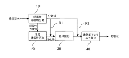
- FIG. 1 (a) is an explanatory view of the first embodiment of the treatment system according to the present invention
- FIG. 1 (b) is such that the ammonia nitrogen concentration and nitrite nitrogen concentration of the anaerobic digestion liquid are 1: 1.32. It is explanatory drawing of the free nitrous acid density
- FIG. 2 is an explanatory diagram of a second embodiment of the processing system according to the present invention.
- FIG. 3 is an explanatory diagram of a third aspect of the processing system according to the present invention.
- FIG. 4 is an explanatory diagram of a fourth aspect of the processing system according to the present invention.
- FIG. 5 is an explanatory diagram of a fifth aspect of the processing system according to the present invention.
- FIG. 6 is an explanatory diagram of a sixth aspect of the processing system according to the present invention.
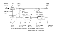
- FIG. 7 is an explanatory diagram of a numerical simulation of the processing system according to the present invention.
- FIG. 8 is an explanatory diagram of a numerical simulation of the processing system according to the present invention.
- FIG. 1 (a) shows a treatment system for waste water containing suspended organic substances according to the first embodiment.
- the said processing system is a system which purifies the to-be-processed water containing suspended organic substance, suspended organic substance separation apparatus 10, sludge anaerobic digester 20, nitritation apparatus 30, and autotrophic desorption.
- a nitrogen device 40 and a first transfer path R1 are provided.
- the suspension organic matter separation device 10 In the suspension organic matter separation device 10, the suspension organic matter contained in the water to be treated is separated, and in the sludge anaerobic digestion device 20, the suspension organic matter separated in the suspension organic matter separation device 10 is anaerobic digestion. Is done.
- ammonia contained in the digestion liquid of the sludge anaerobic digestion apparatus 20 is oxidized to nitrous acid under aerobic conditions.
- the treatment liquid of the nitritation apparatus 30 is used.
- the contained ammonia and nitrous acid are converted to nitrogen gas by autotrophic denitrifying microorganisms under anaerobic conditions.
- the separated liquid from which the suspended organic matter has been removed by the suspended organic matter separation device 10 is supplied to the nitritation device 30 via the first transfer path R1.
- the suspending organic matter separation device 10 can be configured by any of a precipitation device, a coagulation precipitation device, a flotation separation device, a screen device, a membrane separation device, a cyclone device, and a mechanical separation device such as a screw press or a decanter. Further, these devices can be combined.
- the suspended organic matter separated from the water to be treated by the suspended organic matter separation device 10 is anaerobically digested by the sludge anaerobic digester 20 to become a digestive liquid containing ammonia nitrogen.
- the digested liquid containing ammonia nitrogen charged into the nitritation apparatus 30 is subjected to nitritation treatment by nitrite bacteria under aerobic conditions, and a part of the ammonia nitrogen is oxidized to nitrite nitrogen. .
- the treatment liquid of the nitritation apparatus 30 charged into the autotrophic denitrification apparatus 40 is converted to ammonia nitrogen by the autotrophic denitrification microorganisms under anaerobic conditions. It is denitrified by an anaerobic ammonia oxidation treatment using an electron donor and nitrite nitrogen as an electron acceptor. That is, the autotrophic denitrification device 40 is an anaerobic ammonia oxidation device.
- the autotrophic denitrifying microorganisms are held in the autotrophic denitrification apparatus 40 in the form of airborne bacteria and fixed by immobilizing the biofilm adhered to the filler or the autotrophic denitrifying microorganisms on the immobilizing material. It can also be held in the autotrophic denitrification apparatus 40 as a nitrifying carrier.
- the biofilm filling amount into autotrophic denitrification apparatus 40 is preferably 20 to 80% by volume in the case of a fixed bed type.
- a material such as a nonwoven fabric, a plastic material, a sponge material, or porous ceramics can be used, and various shapes such as a plate shape, a granular shape, and a cylindrical shape can be adopted.
- a carrier such as a sphere or cylinder
- a string material, a gel material, or a nonwoven material can be adopted, and a material with many irregularities that easily attach microorganisms is used as a carrier. It is preferable to adopt.
- microorganisms to be immobilized and monomers or prepolymers as carriers are mixed and then polymerized to entrapped and immobilize microorganisms.
- the monomer material acrylamide, methylenebisacrylamide, triacryl formal and the like can be preferably used, and as the prepolymer material, polyethylene glycol diacrylate and polyethylene glycol methacrylate can be preferably used. If an immobilizing material with many irregularities is employed in the same manner as the above-described adhesion fixing, the contact efficiency with the water to be treated is good and the denitrification ability is improved.
- the anaerobic ammonia oxidation process performed in the autotrophic denitrification apparatus 40 is a process of converting 1 equivalent of ammonia nitrogen and 1.32 equivalents of nitrite nitrogen into nitrogen molecules by a denitrification reaction. It is. Therefore, in order to efficiently perform the anaerobic ammonia oxidation treatment, ideally, the nitritation treatment is preferably performed in the nitritation apparatus 30 so that the molar ratio of ammonia to nitrous acid is 1: 1.32. .
- the digested liquid obtained by digesting the high-concentration suspended organic substance contains high-concentration ammonia nitrogen, the nitrite concentration (free nitrous acid concentration) in the nitritation apparatus 30 tends to increase. is there.
- the free nitrous acid concentration (FNA) is expressed by the following formula. That is, the free nitrous acid concentration (FNA) is determined by the nitrous acid concentration, temperature, and pH.
- FIG. 1 (b) shows the calculation of the free nitrous acid concentration based on the above equation when the nitrous acid concentration of the anaerobic digestion solution is 1: 1.32. The value is shown.
- nitritation is performed so that the concentration of nitrite nitrogen is 570 ppm.
- the pH is 7.4 and the water temperature is 30 ° C.
- the concentration of free nitrous acid becomes 0.151 ppm, and nitritation is not hindered.
- the pH is lowered to 7.2, the concentration of free nitrous acid becomes 0.239 ppm, resulting in a concentration that hinders nitritation.
- the separation liquid is supplied to the nitritation apparatus 30 via the first transfer path R1.
- the nitrite nitrogen concentration is about 470 ppm
- the free nitrite concentration can be brought to a level that does not hinder nitritation.
- the free nitrous acid concentration becomes 0.224 ppm, but maintaining a good state for nitritation by diluting the nitrite nitrogen concentration to about 500 ppm without increasing the water temperature. Can do.
- the free nitrous acid concentration becomes 0.302 ppm at a pH of 7.4 and a water temperature of 30 ° C.
- the concentration of free nitrous acid can be controlled to be less than 0.2 ppm.
- a large amount of alkaline agent and enormous energy for heating are required.
- the free nitrite concentration can be brought to a level that does not hinder nitritation.
- the separation liquid is supplied to the nitritation apparatus 30 via the first transfer path R1 to dilute the digestion liquid in the nitritation apparatus 30 so that the digestion liquid in the nitritation apparatus 30 is diluted.
- the nitrous acid concentration (free nitrous acid concentration) can be adjusted to a concentration suitable for ammonia nitritation.
- FIG. 1A an example in which the diluent supplied to the nitritation device 30 via the first transfer path R ⁇ b> 1 is a separation solution from which the suspended organic matter has been removed by the suspended organic matter separation device 10.
- a biological treatment apparatus for biologically treating the separation liquid using aerobic microorganisms is provided, nitrous acid is used as a dilution liquid instead of the separation liquid. It may be supplied to the conversion apparatus 30. This aspect will be described in detail later.
- the nitrifying apparatus 30 can efficiently nitrify ammonia without being inhibited by the ammonia oxidizing bacteria, and the nitrifying apparatus 30 can sufficiently nitrify ammonia.
- the treatment liquid of the nitrite treatment device 30 is efficiently anaerobic ammonia oxidation treatment and denitrification treatment by the autotrophic denitrification device 40. Since the separation liquid or a treatment liquid obtained by biological treatment of the separation liquid is used to adjust the nitrous acid concentration (free nitrous acid concentration) of the digestion liquid, a separate dilution water supply device such as tap water is prepared. There is no need to do. Electricity costs and chemical costs for temperature control and pH control for efficient nitritation reaction can be saved.
- the suspension organic matter separation treatment for separating the suspension organic matter from the water to be treated containing the suspension organic matter and the suspension organic matter separated by the suspension organic matter separation treatment are anaerobically digested.
- autotrophic denitrification treatment that oxidizes to nitrogen gas by autotrophic denitrification microorganisms was performed, and the separated organic solution from which suspended organic matter was removed by the suspension organic matter separation treatment or the separated solution was biologically treated
- the treatment liquid is transferred to nitritation treatment, and a method for treating suspended organic matter-containing wastewater that adjusts the free nitrous acid concentration in the nitritation treatment step is executed.
- FIG. 2 shows the processing system of the second aspect.
- the processing system includes a second transfer path R2 that supplies the separation liquid to the autotrophic denitrification apparatus 40.
- the autotrophic denitrification apparatus 40 As described above, in the autotrophic denitrification apparatus 40, ammonia nitrogen is used as an electron donor by the autotrophic denitrification microorganisms under anaerobic conditions with respect to the treatment liquid of the nitritation apparatus 30, and nitrite nitrogen is converted. Denitrification is performed by anaerobic ammonia oxidation treatment as an electron acceptor. At this time, if the concentration of nitrous acid (free nitrous acid concentration) in the autotrophic denitrification apparatus 40 is high, the efficiency of the anaerobic ammonia oxidation treatment is lowered.
- the processing liquid in the autotrophic denitrification apparatus 40 is diluted, and the nitrous acid concentration (free nitrous acid concentration) of the processing liquid is It is adjusted to a concentration suitable for anaerobic ammonia oxidation treatment. Accordingly, the autotrophic denitrification apparatus 40 can efficiently perform anaerobic ammonia oxidation treatment. Since it is the structure which adjusts nitrous acid concentration (free nitrous acid concentration) using a separated liquid, it is not necessary to prepare separate dilution water supply facilities, such as tap water.
- suspended organic matter separation treatment that separates suspended organic matter from water to be treated containing suspended organic matter, and sludge anaerobic that digests suspended organic matter separated by suspended organic matter separation treatment
- Nitrite treatment that oxidizes ammonia contained in digestion solution by digestion treatment and sludge anaerobic digestion to nitrous acid under aerobic conditions, and anaerobic condition of ammonia and nitrite contained in treatment solution by nitrite treatment
- the autotrophic denitrification process that converts it to nitrogen gas was performed, and the suspended organic matter was removed by the suspension organic matter separation treatment or the separated solution was biologically treated.
- a treatment method for wastewater containing suspended organic substances is performed, wherein the treatment liquid is transferred to nitritation treatment and autotrophic denitrification treatment, and the concentration of free nitrous acid in each treatment step is adjusted. .
- the free nitrous acid concentration is preferably adjusted to less than 0.2 ppm, and the autotrophic denitrification process is preferably adjusted to a free nitrous acid concentration of less than 0.08 ppm. Less than is more preferable.
- ammonia is efficiently nitrified by adjusting the free nitrous acid concentration to less than 0.2 ppm.
- the autotrophic denitrification process the anaerobic ammonia oxidation process can be efficiently performed by adjusting the free nitrous acid concentration to less than 0.08 ppm. That is, nitrogen can be removed efficiently even with wastewater containing a high concentration of suspended organic matter.
- FIG. 3 shows the processing system of the third aspect.
- the processing system includes a third transfer path R3 that returns the denitrification liquid processed by the autotrophic denitrification device 40 to the autotrophic denitrification device 40. It is characterized by that. Note that the second transfer path R2 is not necessarily provided.
- the dilution of the processing liquid in the autotrophic denitrification apparatus 40 may not be sufficient only by supplying the separation liquid via the first transfer path R1 and the second transfer path R2. Even in such a case, the denitrification liquid treated by the autotrophic denitrification apparatus 40 is returned to the autotrophic denitrification apparatus 40 through the third transfer route R3, so that the inside of the autotrophic denitrification apparatus 40 The treatment liquid can be further diluted. Therefore, the nitrite concentration (free nitrous acid concentration) of the treatment liquid in the autotrophic denitrification device 40 can be reliably adjusted without supplying dilution water to the autotrophic denitrification device 40 from outside the system. Can be done.
- nitrous acid and ammonia remain in addition to nitric acid in the denitrification liquid treated by the autotrophic denitrification apparatus 40.
- a sensor for measuring nitrite ions and ammonia ions is provided in the autotrophic denitrification device 40, and the denitrification liquid discharged from the autotrophic denitrification device 40 to the outside of the system according to the remaining nitrous acid and ammonia. It is preferable to adjust the return amount so as to satisfy the discharge standard.
- suspended organic matter separation treatment that separates suspended organic matter from water to be treated containing suspended organic matter, and sludge anaerobic that digests suspended organic matter separated by suspended organic matter separation treatment
- Nitrite treatment that oxidizes ammonia contained in digestion solution by digestion treatment and sludge anaerobic digestion to nitrous acid under aerobic conditions, and anaerobic condition of ammonia and nitrite contained in treatment solution by nitrite treatment
- autotrophic denitrification treatment that converts to nitrogen gas is performed, and the separated liquid from which suspended organic substances have been removed by the suspension organic matter separation treatment is transferred to nitritation treatment,
- the treatment liquid or both of the separation liquid and the treatment liquid are transferred to an autotrophic denitrification treatment, and a method for treating suspending organic substance-containing wastewater that adjusts the concentration of free nitrous acid in each treatment step is executed.
- FIG. 4 shows a processing system according to the fourth aspect.
- the treatment system reduces nitric acid contained in the denitrification liquid of the autotrophic denitrification apparatus 40 to nitrogen gas by heterotrophic denitrification microorganisms under anaerobic conditions.
- a heterotrophic denitrification apparatus 50 is provided, and a fourth transfer path R4 for returning the denitrification liquid processed by the heterotrophic denitrification apparatus 50 to the autotrophic denitrification apparatus 40 is provided.
- route R5 which supplies the separation liquid of the suspension organic substance separation apparatus 10 to the heterotrophic denitrification apparatus 50.
- the second transfer path R2 is not necessarily provided.
- heterotrophic denitrification apparatus 50 a denitrification reaction by a heterotrophic denitrification microorganism using nitrate nitrogen generated by anaerobic ammonia oxidation treatment as an electron acceptor and organic matter dissolved in the separation liquid as an electron donor.
- the amount of nitric acid and organic matter discharged from the autotrophic denitrification apparatus 40 to the outside of the system can be reduced by advancing the process.
- the nitritation apparatus 30 may be adjusted so that the nitrous acid is larger than the molar ratio of 1.32 with ammonia. In some cases, nitrification may proceed to nitric acid. However, in order to increase the efficiency of denitrification and reduce the amount of oxygen required for nitrification, it is desirable that ammonia: nitrous acid is adjusted to about 1: 1.32 to 1.5 in the nitritation apparatus 30.
- the treatment liquid in the autotrophic denitrification apparatus 40 is further diluted. can do. Therefore, the nitrite concentration (free nitrous acid concentration) of the treatment liquid in the autotrophic denitrification apparatus 40 can be adjusted reliably.
- the heterotrophic denitrification apparatus 50 is charged with heterotrophic denitrification microorganisms and is maintained in an anaerobic atmosphere.
- the retention form of the heterotrophic denitrification microorganisms in the heterotrophic denitrification apparatus 50 is the same retention form as the autotrophic denitrification microorganisms in the autotrophic denitrification apparatus 40 described in the processing system of the first aspect. Can be adopted.
- the heterotrophic denitrification apparatus 50 is separated into the suspended organic substance separation apparatus 10 via the fifth transfer path R5. By supplying, the lack of organic matter can be compensated.
- the separation liquid from which the suspended organic matter has been removed by the suspended organic matter separation device 10 is supplied to the nitritation device 30 via the first transfer path R1.
- the configuration for supplying the anaerobic ammonia oxidation apparatus 40 via the second transfer path R2 has been described, but the diluent supplied via the transfer paths R1, R2 is not limited to the separation liquid, and the separation liquid A treatment solution in which the organic matter concentration is reduced by biological treatment may be used as a diluent.
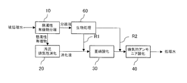
- FIG. 5 shows the processing system of the fifth aspect.
- the treatment system includes a biological treatment device 60 that biologically treats the separated liquid of the suspending organic matter separation device 10, and nitrites the biologically treated treatment solution. It is configured to supply to the device 30. It should be noted that the same configuration can be adopted in the processing system of any of the first, third, and fourth modes.
- the biological treatment apparatus 60 can illustrate an aeration tank.
- FIG. 6 shows the processing system of the sixth aspect.
- liquid organic waste is supplied to the sludge anaerobic digester 20 of the treatment system according to the first aspect described above from a route different from the suspended organic matter supplied from the suspended organic matter separation device 10. It is configured to flow in.
- the liquid organic waste is preferably food waste, sludge generated by wastewater treatment, livestock manure, and the like.
- the processing system of the second to fifth aspects can have the same configuration.
- the liquid organic waste is introduced into the sludge anaerobic digester from outside the system, and ammonia Even if the amount generated is increased, the nitrous acid concentration (free nitrous acid concentration) in the nitrifying device can be adjusted by the separated liquid from which the suspending organic matter has been removed by the suspending organic matter separating device. Efficient nitrogen removal becomes possible by the ammonia oxidation treatment.
- FIG. 7 shows the result of a numerical simulation performed on the processing system of the second mode described in FIG. 200 m 3 / d treated water flows into the treatment system.
- the suspending organic matter separation device 10 separates 10 m 3 / d suspending organic matter contained in the water to be treated.
- the concentration of ammonia nitrogen and nitrite nitrogen in the 190 m 3 / d separation liquid of the suspending organic matter separation apparatus 10 is 0 ppm for convenience.
- the suspended organic matter separated by the suspended organic matter separation device 10 is anaerobically digested by the sludge anaerobic digester 20.
- the digestive fluid contains 5000 ppm of ammonia nitrogen.
- the nitritation apparatus 30 is kept aerobic at a temperature of 30 ° C. and pH 7.4, and ammonia contained in the anaerobic digestion liquid of the sludge anaerobic digestion apparatus 20 has a molar ratio of ammonia to nitrous acid of about 1: 1. Nitrite to 3. Therefore, when nitrifying 5000 ppm of ammonia nitrogen as it is, it becomes 2160 ppm of ammonia nitrogen and 2840 ppm of nitrite nitrogen. At this time, the free ammonia concentration is 53.8 ppm and the free nitrous acid concentration is 0.75 ppm.
- the concentration of free ammonia is determined by the formula of Anthonisen et al., which is obtained by measuring the ammonium ion concentration of water to be treated by a diaphragm type ion electrode method or the like and calculating from the relationship between temperature and pH as shown in the following formula 2. The method can be adopted.
- the concentration of free nitrous acid can be reduced to a level of 0.2 ppm or less that does not interfere with nitritation. it can.
- the ammonia nitrogen contained in the digested liquid after dilution will be 1250 ppm.
- the digested liquid after this dilution is nitritized by the nitritation apparatus 30, it becomes 543 ppm of ammonia nitrogen and 707 ppm of nitrite nitrogen.
- the free nitrous acid concentration is 0.19 ppm. That is, it is possible to achieve a free nitrous acid concentration of less than 0.2 ppm by diluting the digestive fluid four times.
- the digestive fluid of the sludge anaerobic digester 20 is 10 m. 3 / d was diluted 5.5 times with 45 m 3 / d separation.
- the digestive juice is diluted so that the concentration of free nitrous acid is less than 0.2 ppm, but it is more preferable to dilute so that the concentration of free ammonia is in the range of 0.1 to 10 ppm.
- the autotrophic denitrification apparatus 40 is kept anaerobic at a temperature of 30 ° C. and pH 7.4, and denitrifies the treatment liquid of the nitritation apparatus 30 by anaerobic ammonia oxidation treatment.
- the concentration of free nitrous acid in the treatment liquid of the nitritation treatment apparatus 30 is 0.13 ppm. This free nitrous acid concentration of 0.13 ppm exceeds the free nitrous acid concentration, which is a condition for efficient anaerobic ammonia oxidation treatment, by 0.08 ppm. Therefore, the efficiency of the anaerobic ammonia oxidation treatment is lowered as it is.
- the concentration of free nitrous acid is 0.053 ppm, which is less than 0.08 ppm, which is a condition for efficient anaerobic ammonia oxidation treatment.
- nitrous acid nitrogen becomes 300 ppm by 1.7 times dilution,
- free nitrous acid concentration will be 0.079 ppm and will be less than 0.08 ppm, but it will be less than 0.06 ppm which can be processed more efficiently. Diluted.
- FIG. 8 shows the result of a numerical simulation performed on the processing system of the third aspect described in FIG.
- the processing system is the processing system of the third aspect described in FIG. 200 m 3 / d treated water flows into the treatment system.
- the suspending organic matter separation device 10 separates the suspending organic matter 20 m 3 / d contained in the water to be treated.
- the concentration of ammonia nitrogen and nitrite nitrogen in the 180 m 3 / d separation liquid of the suspending organic matter separation apparatus 10 is 0 ppm for convenience.
- the suspended organic matter separated by the suspended organic matter separation device 10 is anaerobically digested by the sludge anaerobic digester 20.
- the digestive fluid contains 5000 ppm of ammonia nitrogen.
- the nitritation apparatus 30 is kept aerobic at a temperature of 30 ° C. and pH 7.4, and ammonia contained in the anaerobic digestion liquid of the sludge anaerobic digestion apparatus 20 has a molar ratio of ammonia to nitrous acid of about 1: 1. Nitrite to 3. Therefore, when nitrifying 5000 ppm of ammonia nitrogen as it is, it becomes 2160 ppm of ammonia nitrogen and 2840 ppm of nitrite nitrogen. At this time, the free ammonia concentration is 53.8 ppm and the free nitrous acid concentration is 0.75 ppm.
- the free ammonia concentration is 9.7 ppm
- the free nitrous acid concentration is 0.13 ppm. In this way, by supplying the separation liquid to the nitritation device 30 via the first transfer path R1, the free nitrous acid concentration can be reduced to less than 0.2 ppm that does not interfere with nitritation.
- the autotrophic denitrification apparatus 40 is kept anaerobic at a temperature of 30 ° C. and pH 7.4, and denitrifies the treatment liquid of the nitritation apparatus 30 by anaerobic ammonia oxidation treatment.
- the concentration of free nitrous acid in the treatment liquid of the nitritation treatment apparatus 30 is 0.13 ppm. This free nitrous acid concentration of 0.13 ppm exceeds the free nitrous acid concentration, which is a condition for efficient anaerobic ammonia oxidation treatment, by more than 0.06 ppm, so that the efficiency of the anaerobic ammonia oxidation treatment is lowered as it is.
- the free nitrous acid concentration at this time becomes 0.053 ppm, which is a condition for efficient anaerobic ammonia oxidation treatment. Less than 0.06 ppm can be achieved.
- the separation liquid separated by the suspending organic matter separation device 10 is only 90 m 3 / d.
- the remaining 90 m 3 / d of the separation liquid separated by the suspending organic matter separation device 10 is supplied to the autotrophic denitrification device 40 via the second transfer path R2, and the autotrophic denitrification is also performed.
- 80 m 3 / d is returned to the autotrophic denitrification apparatus 40 via the third transfer path R3.
- the 110 m 3 / d treatment liquid of the nitritation apparatus 30 is supplied via the 90 m 3 / d separation liquid supplied via the first transfer path R 1 and the third transfer path R 3. Furthermore, it can be diluted about 2.55 times with a denitrification solution of 80 m 3 / d. Then, the nitrite nitrogen in the treatment liquid of the nitritation treatment apparatus 30 is diluted from 510 ppm to 200 ppm. At this time, the concentration of free nitrous acid is 0.053 ppm, and can be made less than 0.06 ppm, which is a condition for efficient anaerobic ammonia oxidation treatment.
- the 110 m 3 / d digested liquid of the nitritation apparatus 30 is passed through the 90 m 3 / d separation liquid supplied via the first transfer path R 1 and the third transfer path R 3.
- the case of diluting about 2.55 times with the supplied 90 m 3 / d denitrification liquid has been described, but the distribution of the separation liquid and denitrification liquid used for dilution of the treatment liquid of the nitritation apparatus 30 is as follows.
- only 110 m 3 / d denitrification liquid supplied through the third transfer path R 3 without using a separation liquid is used as the 110 m 3 / d treatment liquid of the nitritation apparatus 30. You may comprise so that it may be diluted with.
- the denitrification liquid of the heterotrophic denitrification device 50 is sublimated. You may use for the dilution of the process liquid of the nitrification apparatus 30.
- Suspended organic matter separation device 20 Sludge anaerobic digester 30: Nitrite device 40: Autotrophic denitrification device 50: Heterotrophic denitrification device 60: Biological treatment device
Landscapes
- Life Sciences & Earth Sciences (AREA)
- Biodiversity & Conservation Biology (AREA)
- Microbiology (AREA)
- Hydrology & Water Resources (AREA)
- Engineering & Computer Science (AREA)
- Environmental & Geological Engineering (AREA)
- Water Supply & Treatment (AREA)
- Chemical & Material Sciences (AREA)
- Organic Chemistry (AREA)
- Purification Treatments By Anaerobic Or Anaerobic And Aerobic Bacteria Or Animals (AREA)
- Treatment Of Sludge (AREA)
Description
本発明は、懸濁性有機物含有廃水の処理システム及び処理方法に関し、特に高濃度の懸濁性有機物を含有する廃水に好適な処理システム及び処理方法に関する。
従来、高濃度の懸濁性有機物を含有する廃水を処理する際には、先ず廃水から懸濁性有機物を分離除去し、その後に分離液を硝化脱窒法等の生物学的処理工程で処理する方法が採用されてきた。廃水から分離除去された懸濁性有機物は、そのまま脱水処理され、或いは減量化やメタンガス回収を目的とした嫌気性消化処理された後に処分される。そして、これらの処理の際に発生する脱水ろ液や消化液は、生物学的処理工程に返流されて、分離液とともに処理される。
硝化脱窒法は、廃水中のアンモニア態窒素をアンモニア酸化細菌により亜硝酸態窒素に酸化し、更に亜硝酸態窒素を亜硝酸酸化細菌により硝酸態窒素に酸化する硝化工程と、亜硝酸態窒素及び硝酸態窒素を従属栄養性の脱窒菌により窒素分子にまで分解する脱窒工程を経て、廃水中のアンモニア態窒素を窒素分子にまで分解する方法である。
しかし、このような従来の生物学的硝化脱窒法では、硝化工程で大量の酸素が必要となり、曝気のためのブロワファン等に要する電力コストが高騰するという問題、脱窒工程で有機炭素源として大量のメタノール等を添加する必要があり、そのための薬品コストが高騰するという問題、さらに従属栄養性脱窒微生物を用いるために汚泥発生量が多く、余剰汚泥の処理コストが嵩むという問題等、ランニングコストが嵩むという問題があった。
そこで、特許文献1では、SS性有機物及びアンモニア態窒素を含有する対象処理液を固液分離する固液分離手段と、前記固液分離手段で分離された分離汚泥を嫌気性消化処理する嫌気性消化槽と、前記嫌気性消化槽の処理液を亜硝酸化処理する亜硝酸化槽と、前記亜硝酸化槽の硝化液と前記固液分離手段の分離液を混合して脱窒処理する脱窒槽を備えた生物学的窒素除去システムが提案されている。
当該生物学的窒素除去システムは、SS性有機物及びアンモニア態窒素を含有する対象処理液を固液分離して得られた分離汚泥を嫌気性消化した後、嫌気性消化により得られた処理液を亜硝酸化処理した硝化液と、前記対象処理液を固液分離して得られた分離液とを、嫌気的アンモニア酸化処理により脱窒するシステムである。
嫌気的アンモニア酸化処理とは、嫌気条件下で独立栄養性脱窒微生物(独立栄養性脱窒菌)によるアンモニア態窒素を電子供与体とし、亜硝酸態窒素を電子受容体として、以下の式で表されるように、1当量のアンモニア態窒素と1.32当量の亜硝酸態窒素とを脱窒反応によって窒素分子に変換する処理である。この際、0.26当量の硝酸が生成される。
NH4 ++1.32NO2 -+0.066HCO3 -+0.13H+→
1.02N2+0.26NO3 -+0.066CH2O0.5N0.15+2.03H2O
NH4 ++1.32NO2 -+0.066HCO3 -+0.13H+→
1.02N2+0.26NO3 -+0.066CH2O0.5N0.15+2.03H2O
高濃度の懸濁性有機物を含有する廃水を、特許文献1に記載された生物学的窒素除去システムで処理すると、沈殿槽で分離された多量の分離汚泥が嫌気性消化処理されて高濃度のアンモニアが発生する。発生したアンモニアは硝化槽で亜硝酸化され、沈殿槽の分離液とともに脱窒槽で嫌気的アンモニア酸化処理されて脱窒される。
しかし、当該生物学的窒素除去システムでは、硝化槽内の亜硝酸濃度(遊離亜硝酸濃度)が高くなると、アンモニア酸化細菌の活性が阻害されて亜硝酸化反応の効率が低下する。そして、硝化槽で亜硝酸化されなかった多量のアンモニア態窒素が脱窒槽に流入する結果、脱窒槽では亜硝酸態窒素に対してアンモニア態窒素が過多となり、処理しきれないアンモニアがリークするという問題があった。
本発明の目的は、上述した問題点に鑑み、従来技術より効率的な処理が可能となり、さらには、高濃度の懸濁性有機物を含有する廃水であっても、より効率的な懸濁性有機物含有廃水の処理システム及び処理方法を提供する点にある。
上述の目的を達成するため、本発明による懸濁性有機物含有廃水の処理システムの第一の特徴構成は、特許請求の範囲の書類の請求項1に記載した通り、懸濁性有機物を含有する被処理水から懸濁性有機物を分離する懸濁性有機物分離装置と、前記懸濁性有機物分離装置により分離された懸濁性有機物を嫌気性消化する汚泥嫌気性消化装置と、前記汚泥嫌気性消化装置の消化液に含まれるアンモニアを好気条件下で亜硝酸に酸化する亜硝酸化装置と、前記亜硝酸化装置の処理液に含まれるアンモニアを嫌気条件下で独立栄養性脱窒微生物によって窒素ガスに酸化する独立栄養性脱窒装置と、を有する懸濁性有機物含有廃水の処理システムであって、前記懸濁性有機物分離装置で懸濁性有機物が除去された分離液または当該分離液を生物処理した処理液を前記亜硝酸化装置に供給する第1移送経路を備えている点にある。
懸濁性有機物分離装置により被処理水から分離された懸濁性有機物が汚泥嫌気性消化装置で嫌気性消化される。嫌気性消化によりアンモニアを含有した消化液は亜硝酸化装置に導入されて好気条件下で亜硝酸に酸化され、アンモニアと亜硝酸を含む処理液が独立栄養性脱窒装置に導入される。独立栄養性脱窒装置では、嫌気条件下で、独立栄養性脱窒微生物によって処理液に含まれるアンモニア態窒素を電子供与体とし亜硝酸態窒素を電子受容体とする嫌気的アンモニア酸化処理により脱窒処理される。亜硝酸化装置でアンモニアが亜硝酸に酸化される際に、亜硝酸濃度(遊離亜硝酸濃度)が所定濃度よりも高くなると、アンモニア酸化細菌の活性が阻害されて亜硝酸化反応の効率が低下し、後段の独立栄養性脱窒装置で脱窒処理の効率が低下する。
しかし、そのような状況であっても、第1移送経路を経由して、懸濁性有機物分離装置で懸濁性有機物が除去された分離液または当該分離液を生物処理した処理液が亜硝酸化装置に供給されるので、亜硝酸化装置内の硝化液の亜硝酸濃度(遊離亜硝酸濃度)がアンモニアの亜硝酸化処理に適した濃度に調整され、亜硝酸化反応が促進されるようになる。尚、このような構成によれば、水道水等を用いた別途の希釈水供給設備を準備する必要がなく、特段の温度制御やpH制御をすることなく、亜硝酸化反応を促進することができる。水道水や電力等のエネルギーコストや薬品コストを節約できるようになる。
同第二の特徴構成は、同請求項2に記載した通り、上述した第一の特徴構成に加えて、前記懸濁性有機物分離装置の分離液または当該分離液を生物処理した処理液を前記独立栄養性脱窒装置に供給する第2移送経路を備えている点にある。
独立栄養性脱窒装置では、亜硝酸化装置の処理液に含まれるアンモニアが嫌気条件下で独立栄養性脱窒微生物によって窒素ガスに酸化される。しかし、独立栄養性脱窒装置に導入される処理液の亜硝酸濃度(遊離亜硝酸濃度)が高くなると嫌気的アンモニア酸化処理の処理効率が低下する。
しかし、そのような状況であっても、第2移送経路を経由して、懸濁性有機物分離装置で懸濁性有機物が除去された分離液または当該分離液を生物処理した処理液が独立栄養性脱窒装置に供給されるので、独立栄養性脱窒装置内の処理液の亜硝酸濃度(遊離亜硝酸濃度)が嫌気的アンモニア酸化処理に適した濃度になるように独立栄養性脱窒装置内の処理液が希釈され、効率的な嫌気的アンモニア酸化処理が促進されるようになる。同様に、このような構成によれば、水道水等を用いた別途の希釈水供給設備を準備する必要がない。
同第三の特徴構成は、同請求項3に記載した通り、上述した第一または第二の特徴構成に加えて、前記独立栄養性脱窒装置で処理した脱窒液を前記独立栄養性脱窒装置に返送する第3移送経路を備えている点にある。
上述の分離液または当該分離液を生物処理した処理液の投入により独立栄養性脱窒装置内の処理液の亜硝酸濃度(遊離亜硝酸濃度)を適正な値に希釈できない場合であっても、第3移送経路を経由して、独立栄養性脱窒装置で処理され、亜硝酸濃度が低下した脱窒液が独立栄養性脱窒装置に返送されるので、独立栄養性脱窒装置内の処理液の亜硝酸濃度(遊離亜硝酸濃度)が適正な値になるように、さらに希釈できるようになる。同様に、このような構成によれば、水道水等を用いた別途の希釈水供給設備を準備する必要がない。
同第四の特徴構成は、同請求項4に記載した通り、上述した第一または第二特徴構成に加えて、前記独立栄養性脱窒処理装置の脱窒液に含有する硝酸を嫌気条件下で従属栄養性脱窒微生物によって窒素ガスに還元する従属栄養性脱窒装置を備え、前記従属栄養性脱窒装置で処理した脱窒液を前記独立栄養性脱窒装置に返送する第4移送経路を備えている点にある。
独立栄養性脱窒処理装置で嫌気的アンモニア酸化処理された脱窒液には硝酸が含まれる。そのような脱窒液が従属栄養性脱窒装置に導入されることにより、脱窒液に含まれる硝酸が嫌気条件下で従属栄養性脱窒微生物によって窒素ガスに還元されるようになる。第4移送経路を経由して、従属栄養性脱窒装置で処理された脱窒液が独立栄養性脱窒装置に返送されるので、独立栄養性脱窒装置内の処理液の亜硝酸濃度(遊離亜硝酸濃度)が適正な値になるように、さらに希釈できるようになる。
本発明による懸濁性有機物含有廃水の処理方法の第一の特徴構成は、同請求項5に記載した通り、懸濁性有機物を含有する被処理水から懸濁性有機物を分離する懸濁性有機物分離処理と、前記懸濁性有機物分離処理により分離された懸濁性有機物を嫌気性消化する汚泥嫌気性消化処理と、前記汚泥嫌気性消化処理による消化液に含まれるアンモニアを好気条件下で亜硝酸に酸化する亜硝酸化処理と、前記亜硝酸化処理による処理液に含まれるアンモニアを嫌気条件下で独立栄養性脱窒微生物によって窒素ガスに酸化する独立栄養性脱窒処理と、を行なう懸濁性有機物含有廃水の処理方法であって、前記懸濁性有機物分離処理で懸濁性有機物が除去された分離液または当該分離液が生物処理された処理液を、前記亜硝酸化処理と前記独立栄養性脱窒処理に移送し、それぞれの処理工程での遊離亜硝酸濃度を調節する点にある。
同第二の特徴構成は、同請求項6に記載した通り、懸濁性有機物を含有する被処理水から懸濁性有機物を分離する懸濁性有機物分離処理と、前記懸濁性有機物分離処理により分離された懸濁性有機物を嫌気性消化する汚泥嫌気性消化処理と、前記汚泥嫌気性消化処理による消化液に含まれるアンモニアを好気条件下で亜硝酸に酸化する亜硝酸化処理と、前記亜硝酸化処理による処理液に含まれるアンモニアを嫌気条件下で独立栄養性脱窒微生物によって窒素ガスに酸化する独立栄養性脱窒処理と、を行なう懸濁性有機物含有廃水の処理方法であって、前記懸濁性有機物分離処理で懸濁性有機物が除去された分離液または当該分離液が生物処理された処理液を前記亜硝酸化処理に移送し、前記処理液または前記分離液と前記処理液の双方を、前記独立栄養性脱窒処理に移送し、それぞれの処理工程での遊離亜硝酸濃度を調節する点にある。
同第三の特徴構成は、同請求項7に記載した通り、上述した第一または第二の特徴構成に加えて、前記亜硝酸化処理の工程は遊離亜硝酸濃度を0.2ppm未満に調整し、前記独立栄養性脱窒処理の工程は遊離亜硝酸濃度を0.08ppm未満に調節する点にある。
亜硝酸化処理の工程では、遊離亜硝酸濃度を0.2ppm未満に調整して実行することで、アンモニアは効率的に亜硝酸化される。前記独立栄養性脱窒処理の工程では、遊離亜硝酸濃度を0.08ppm未満に調節して実行することで、嫌気的アンモニア酸化処理を効率的に行うことができる。つまり、高濃度の懸濁性有機物を含有する廃水であっても効率的に窒素除去できる。
以上説明した通り、本発明によれば、従来技術より効率的な処理が可能となり、さらには、高濃度の懸濁性有機物を含有する廃水であっても、より効率的な懸濁性有機物含有廃水の処理システム及び処理方法を提供することができるようになった。
以下、本発明による懸濁性有機物含有廃水の処理システム及び処理方法の実施形態を説明する。
図1(a)には、第一の態様の懸濁性有機物含有廃水の処理システムが示されている。当該処理システムは、懸濁性有機物を含有する被処理水を浄化するシステムであり、懸濁性有機物分離装置10と、汚泥嫌気性消化装置20と、亜硝酸化装置30と、独立栄養性脱窒装置40と、第1移送経路R1とを備えている。
懸濁性有機物分離装置10では、被処理水に含まれる懸濁性有機物が分離され、汚泥嫌気性消化装置20では、懸濁性有機物分離装置10で分離された懸濁性有機物が嫌気性消化される。
亜硝酸化装置30では、汚泥嫌気性消化装置20の消化液に含まれるアンモニアが好気条件下で亜硝酸に酸化され、独立栄養性脱窒装置40では、亜硝酸化装置30の処理液に含まれるアンモニア及び亜硝酸が嫌気条件下で独立栄養性脱窒微生物によって窒素ガスに変換される。そして、懸濁性有機物分離装置10で懸濁性有機物が除去された分離液が、第1移送経路R1を経由して亜硝酸化装置30に供給される。
懸濁性有機物分離装置10は、沈殿装置、凝集沈殿装置、浮上分離装置、スクリーン装置、膜分離装置、サイクロン装置、スクリュープレスやデカンタ等の機械的分離装置の何れかで構成することができる。また、これらの装置を組み合わせて構成することも可能である。
懸濁性有機物分離装置10で被処理水から分離された懸濁性有機物は、汚泥嫌気性消化装置20で嫌気性消化されて、アンモニア態窒素を含有する消化液となる。
亜硝酸化装置30に投入されたアンモニア態窒素を含有する消化液は、好気条件下で亜硝酸化菌によって亜硝酸化処理され、アンモニア態窒素の一部が亜硝酸態窒素に酸化される。
独立栄養性脱窒装置40に投入された亜硝酸化装置30の処理液、つまりアンモニア態窒素と亜硝酸態窒素を含む処理液は、嫌気条件下で独立栄養性脱窒微生物によってアンモニア態窒素を電子供与体とし、亜硝酸態窒素を電子受容体とする嫌気的アンモニア酸化処理によって脱窒される。つまり、独立栄養性脱窒装置40は嫌気的アンモニア酸化装置である。
独立栄養性脱窒微生物は、浮遊菌の形で独立栄養性脱窒装置40内に保持され、充填材に付着させた生物膜、或いは独立栄養性脱窒微生物を固定化材に固定化した固定化担体として独立栄養性脱窒装置40内に保持することもできる。
独立栄養性脱窒微生物を充填材に付着させた生物膜を採用する場合、独立栄養性脱窒装置40への生物膜の充填量は、固定床式の場合に20~80容積%が好ましい。充填材として、不織布、プラスチック材料、スポンジ材料または多孔質セラミックス等の材質を使用することができ、板状、粒状または筒状等の各種の形状を採用することができる。
独立栄養性脱窒微生物を固定化材に固定化した固定化担体を採用する場合、固定化材への独立栄養性脱窒微生物固定化には、付着固定化及び包括固定化の2つの方法を採用することができる。
付着固定化を採用する場合は、球状や筒状などの担体の他、ひも状材料、ゲル状材料または不織布状材料等を採用することができ、微生物を付着させ易い凹凸の多い材料を担体として採用することが好ましい。
包括固定化を採用する場合は、固定化の対象となる微生物と担体であるモノマやプレポリマを混合した後に重合させて、微生物を包括固定化させる方法を採用するのが一般的である。
モノマ材料として、アクリルアミド、メチレンビスアクリルアミド、トリアクリルフォルマール等が好ましく利用でき、プレポリマ材料として、ポリエチレングリコールジアクリレートやポリエチレングリコールメタアクリレートが好ましく利用できる。上述した付着固定と同様に凹凸の多い形状の固定化材を採用すれば、被処理水との接触効率がよく、脱窒能が向上する。
上述したように、独立栄養性脱窒装置40で行なわれる嫌気的アンモニア酸化処理は、1当量のアンモニア態窒素と1.32当量の亜硝酸態窒素とを脱窒反応によって窒素分子に変換する処理である。従って、効率的に嫌気的アンモニア酸化処理するために、理想的には亜硝酸化装置30でアンモニアと亜硝酸のモル比が1:1.32になるように亜硝酸化処理されることが好ましい。
つまり、高濃度の懸濁性有機物が消化処理された消化液には高濃度のアンモニア態窒素が含まれるため、亜硝酸化装置30内の亜硝酸濃度(遊離亜硝酸濃度)も高くなる傾向にある。
硝化においては、遊離亜硝酸濃度(FNA)が0.2ppm以上になると全ての硝化細菌が阻害を受けると言われている。Anthonisenらの計算式によると、遊離亜硝酸濃度(FNA)は次式で表される。つまり、遊離亜硝酸濃度(FNA)は亜硝酸濃度、温度、pHで決まるのである。

図1(b)は、嫌気性消化液のアンモニア態窒素濃度と亜硝酸態窒素濃度が1:1.32になるように亜硝酸化したときの遊離亜硝酸濃度を、上式に基づいて算出した値が示されている。
嫌気性消化液のアンモニア態窒素濃度が1000ppmのとき、亜硝酸態窒素濃度が570ppmになるように亜硝酸化される。このときにpH7.4、水温30℃であるならば、遊離亜硝酸濃度が0.151ppmとなり、亜硝酸化に支障は生じない。しかし、pHが7.2まで下がると遊離亜硝酸濃度は0.239ppmとなり亜硝酸化に支障が生じる濃度となってしまう。
従来は、pHを上げるためにアルカリ剤を添加していたが、第一の態様の処理システムによれば、第1移送経路R1を経由して、分離液を亜硝酸化装置30に供給して、亜硝酸態窒素濃度が470ppm程度になるように希釈することで、遊離亜硝酸濃度を亜硝酸化に支障のないレベルにすることができる。
水温が15℃になると遊離亜硝酸濃度は0.224ppmになるが、水温を上げずに亜硝酸態窒素濃度500ppm程度になるように希釈することで、亜硝酸化に良好な状態を維持することができる。
嫌気性消化液のアンモニア態窒素濃度が2000ppmになるとpH7.4、水温30℃の状態で遊離亜硝酸濃度が0.302ppmになる。このとき、pHを7.6、或いは水温を48℃に調節すると遊離亜硝酸濃度は0.2ppm未満に制御できるが、そのために大量のアルカリ剤や加温のための莫大なエネルギーが必要となる。しかし、第一の態様の処理システムによれば、亜硝酸態窒素濃度を740ppm程度に希釈することで、遊離亜硝酸濃度を亜硝酸化に支障のないレベルにすることができる。
このように、第1移送経路R1を介して分離液を亜硝酸化装置30に供給して、亜硝酸化装置30内の消化液を希釈することで、亜硝酸化装置30内の消化液の亜硝酸濃度(遊離亜硝酸濃度)を、アンモニアの亜硝酸化に適した濃度に調整することができる。
図1(a)では、第1移送経路R1を介して亜硝酸化装置30に供給される希釈液が、懸濁性有機物分離装置10で懸濁性有機物が除去された分離液である例を説明したが、好気性微生物を用いて当該分離液を生物処理する生物処理装置を備えている場合には、当該分離液に替えて、当該分離液を生物処理した処理液を希釈液として亜硝酸化装置30に供給してもよい。この態様については、後に詳述する。
亜硝酸化装置30でアンモニア酸化細菌は阻害を受けることなくアンモニアの亜硝酸化を効率的に行なうことができ、亜硝酸化装置30でアンモニアが十分に亜硝酸化することができる。
亜硝酸化処装置30の処理液は独立栄養性脱窒装置40で効率的に嫌気的アンモニア酸化処理され脱窒処理される。前記消化液の亜硝酸濃度(遊離亜硝酸濃度)の調整に、前記分離液または前記分離液を生物処理した処理液を用いる構成であるので、水道水等の別途の希釈水の供給装置を準備する必要がない。効率的な亜硝酸化反応のための温度制御やpH制御のための電力コストや薬品コストを節約できるようになる。
上述の構成により、懸濁性有機物を含有する被処理水から懸濁性有機物を分離する懸濁性有機物分離処理と、懸濁性有機物分離処理により分離された懸濁性有機物を嫌気性消化する汚泥嫌気性消化処理と、汚泥嫌気性消化処理による消化液に含まれるアンモニアを好気条件下で亜硝酸に酸化する亜硝酸化処理と、亜硝酸化処理による処理液に含まれるアンモニアを嫌気条件下で独立栄養性脱窒微生物によって窒素ガスに酸化する独立栄養性脱窒処理とを行ない、懸濁性有機物分離処理で懸濁性有機物が除去された分離液または当該分離液が生物処理された処理液を、亜硝酸化処理に移送し、亜硝酸化処理工程での遊離亜硝酸濃度を調節する懸濁性有機物含有廃水の処理方法が実行される。
図2には、第二の態様の処理システムが示されている。当該処理システムは、上述した第一の態様の処理システムに加え、前記分離液を独立栄養性脱窒装置40に供給する第2移送経路R2を備えていることを特徴とする。
上述したように、独立栄養性脱窒装置40では、亜硝酸化装置30の処理液に対し、嫌気条件下で独立栄養性脱窒微生物によってアンモニア態窒素を電子供与体とし、亜硝酸態窒素を電子受容体とする嫌気的アンモニア酸化処理による脱窒が行なわれる。このとき、独立栄養性脱窒装置40内の亜硝酸濃度(遊離亜硝酸濃度)が高いと、嫌気的アンモニア酸化処理の効率が低下してしまう。
第2移送経路R2により分離液を独立栄養性脱窒装置40に供給することで、独立栄養性脱窒装置40内の処理液は希釈され、処理液の亜硝酸濃度(遊離亜硝酸濃度)は、嫌気的アンモニア酸化処理に適した濃度に調整される。従って、独立栄養性脱窒装置40では効率的な嫌気的アンモニア酸化処理が可能となる。分離液を用いて、亜硝酸濃度(遊離亜硝酸濃度)の調整を行う構成であるため、水道水等の別途の希釈水供給設備を準備する必要がない。
つまり、懸濁性有機物を含有する被処理水から懸濁性有機物を分離する懸濁性有機物分離処理と、懸濁性有機物分離処理により分離された懸濁性有機物を嫌気性消化する汚泥嫌気性消化処理と、汚泥嫌気性消化処理による消化液に含まれるアンモニアを好気条件下で亜硝酸に酸化する亜硝酸化処理と、亜硝酸化処理による処理液に含まれるアンモニア及び亜硝酸を嫌気条件下で独立栄養性脱窒微生物によって窒素ガスに変換する独立栄養性脱窒処理とを行ない、懸濁性有機物分離処理で懸濁性有機物が除去された分離液または当該分離液が生物処理された処理液を、亜硝酸化処理と独立栄養性脱窒処理に移送し、それぞれの処理工程での遊離亜硝酸濃度を調節することを特徴とする懸濁性有機物含有廃水の処理方法が実行される。
尚、亜硝酸化処理の工程は遊離亜硝酸濃度を0.2ppm未満に調整し、独立栄養性脱窒処理の工程は遊離亜硝酸濃度を0.08ppm未満に調節することが好ましく、0.06ppm未満がより好ましい。亜硝酸化処理の工程では、遊離亜硝酸濃度を0.2ppm未満に調整して実行することで、アンモニアは効率的に亜硝酸化される。独立栄養性脱窒処理の工程では、遊離亜硝酸濃度を0.08ppm未満に調節して実行することで、嫌気的アンモニア酸化処理を効率的に行うことができる。つまり、高濃度の懸濁性有機物を含有する廃水であっても効率的に窒素除去できる。
図3には、第三の態様の処理システムが示されている。当該処理システムは、上述の第二の態様の処理システムに加え、独立栄養性脱窒装置40で処理した脱窒液を独立栄養性脱窒装置40に返送する第3移送経路R3を備えていることを特徴とする。尚、第2移送経路R2は必ずしも備える必要はない。
第1移送経路R1及び第2移送経路R2を介した前記分離液の供給だけでは、独立栄養性脱窒装置40内の処理液の希釈が十分でない場合がある。このような場合であっても、第3移送経路R3により独立栄養性脱窒装置40で処理した脱窒液を独立栄養性脱窒装置40に返送することで、独立栄養性脱窒装置40内の処理液をさらに希釈することができる。従って、希釈のための水を系外から独立栄養性脱窒装置40に供給しなくても、独立栄養性脱窒装置40内の処理液の亜硝酸濃度(遊離亜硝酸濃度)の調整を確実に行うことができる。
尚、独立栄養性脱窒装置40で処理した脱窒液には、硝酸に加えて、未処理の亜硝酸やアンモニアが残留している。独立栄養性脱窒装置40に亜硝酸イオンやアンモニアイオンを測定するセンサを備えて、残留する亜硝酸やアンモニアに応じて、独立栄養性脱窒装置40から系外に放流される脱窒液の放流基準を満たすように、返送量を調整することが好ましい。
つまり、懸濁性有機物を含有する被処理水から懸濁性有機物を分離する懸濁性有機物分離処理と、懸濁性有機物分離処理により分離された懸濁性有機物を嫌気性消化する汚泥嫌気性消化処理と、汚泥嫌気性消化処理による消化液に含まれるアンモニアを好気条件下で亜硝酸に酸化する亜硝酸化処理と、亜硝酸化処理による処理液に含まれるアンモニア及び亜硝酸を嫌気条件下で独立栄養性脱窒微生物によって窒素ガスに変換する独立栄養性脱窒処理とを行ない、懸濁性有機物分離処理で懸濁性有機物が除去された分離液を亜硝酸化処理に移送し、前記処理液または前記分離液と前記処理液の双方を、独立栄養性脱窒処理に移送し、それぞれの処理工程での遊離亜硝酸濃度を調節する懸濁性有機物含有廃水の処理方法が実行される。
図4には、第四の態様の処理システムが示されている。当該処理システムは、上述した第二の態様の処理システムに加え、独立栄養性脱窒処理装置40の脱窒液に含有する硝酸を嫌気条件下で従属栄養性脱窒微生物によって窒素ガスに還元する従属栄養性脱窒装置50を備え、従属栄養性脱窒装置50で処理した脱窒液を独立栄養性脱窒装置40に返送する第4移送経路R4を備えている。尚、懸濁性有機物分離装置10の分離液を従属栄養性脱窒装置50に供給する第5移送経路R5を備えてもよい。また、第2移送経路R2は必ずしも備える必要はない。
従属栄養性脱窒装置50では、嫌気的アンモニア酸化処理にて発生した硝酸態窒素を電子受容体とし、分離液に溶解する有機物等を電子供与体とした従属栄養性脱窒微生物による脱窒反応を進行させることで、独立栄養性脱窒装置40から系外に排出される硝酸量や有機物量を低減できるようになる。
ここで、亜硝酸化装置30ではアンモニアと亜硝酸のモル比が1:1.32になるように調節されることが理想であるが、後段の従属栄養性脱窒装置50で嫌気的アンモニア酸化反応で余った亜硝酸を従属栄養性脱窒微生物で脱窒処理することができるので、亜硝酸化装置30では亜硝酸がアンモニアとのモル比1.32より大きくなるように調節すればよい。場合によっては硝酸まで硝化が進行してもよい。ただし、脱窒の効率化や硝化に要する酸素量を低減するために、亜硝酸化装置30ではアンモニア:亜硝酸が1:1.32~1.5程度に調節するのが望ましい。
第4移送経路R4により従属栄養性脱窒装置50で脱窒処理された脱窒液を独立栄養性脱窒装置40に返送することで、独立栄養性脱窒装置40内の処理液をさらに希釈することができる。従って、独立栄養性脱窒装置40内の処理液の亜硝酸濃度(遊離亜硝酸濃度)の調整を確実に行うことができる。
尚、従属栄養性脱窒装置50には、従属栄養性脱窒微生物が投入されており、嫌気性雰囲気に保持される。従属栄養性脱窒装置50内における従属栄養性脱窒微生物の保持形態は、第一の態様の処理システムにおいて説明した独立栄養性脱窒装置40内における独立栄養性脱窒微生物と同様の保持形態を採用することができる。独立栄養性脱窒装置40で処理した脱窒液に含まれる有機物が不足する場合は、従属栄養性脱窒装置50に、第5移送経路R5を介して懸濁性有機物分離装置10の分離液を供給することで、不足する有機物を補うことができる。
上述した第一から第四の態様の処理システムでは、懸濁性有機物分離装置10で懸濁性有機物が除去された分離液を、第1移送経路R1を介して亜硝酸化装置30に供給し、または第2移送経路R2を介して嫌気的アンモニア酸化装置40に供給する構成を説明したが、各移送経路R1,R2を介して供給される希釈液は当該分離液に限られず、当該分離液を生物処理して有機物濃度を低減した処理液を希釈液としてもよい。
図5には、第五の態様の処理システムが示されている。当該処理システムは、上述した第二の態様の処理システムに加え、懸濁性有機物分離装置10の分離液を生物処理する生物処理装置60を備えて、当該生物処理された処理液を亜硝酸化装置30に供給する構成となっている。尚、第一、第三または第四の何れの態様の処理システムでも同様の構成を採用することができる。
懸濁性有機物分離装置10の分離液に含まれるBOD成分が多いと、亜硝酸化装置30や独立栄養性脱窒装置40内で従属栄養性細菌が優勢となってしまい、亜硝酸化や嫌気的アンモニア酸化処理の効率が低下する虞がある。生物処理装置60で分離液に含まれるBODを適当に除去することで、この問題を解決することができる。尚、生物処理装置60は曝気槽が例示できる。
図6には、第六の態様の処理システムが示されている。当該処理システムは、上述した第一の態様の処理システムの汚泥嫌気性消化装置20に、さらに懸濁性有機物分離装置10から供給される懸濁性有機物とは異なるルートから液状有機性廃棄物が流入するように構成されている。当該液状有機性廃棄物は、食品廃棄物、排水処理で生じる汚泥、家畜糞尿等が好適である。第二から第五の態様の処理システムでも同様の構成とすることができる。
上述の第一から第五の態様として示すような本発明による懸濁性有機物含有廃水の処理システム及び処理方法によると、系外から液状有機性廃棄物を汚泥嫌気消化装置に投入して、アンモニア発生量が増加しても、懸濁性有機物分離装置で懸濁性有機物が除去された分離液により亜硝酸化装置内の亜硝酸濃度(遊離亜硝酸濃度)が調整できるので、後段の嫌気性アンモニア酸化処理により効率的な窒素除去が可能となる。
以下に、本発明による処理システムに対して数値シミュレーションを行った結果を説明する。
図7には、図2で説明した第二の態様の処理システムに対して数値シミュレーションを行った結果が示されている。当該処理システムには、200m3/dの被処理水が流入する。懸濁性有機物分離装置10は、被処理水に含まれる10m3/dの懸濁性有機物を分離する。尚、懸濁性有機物分離装置10の190m3/dの分離液のアンモニア態窒素及び亜硝酸態窒素の濃度は便宜上夫々0ppmとする。
懸濁性有機物分離装置10で分離された懸濁性有機物は、汚泥嫌気性消化装置20で嫌気性消化される。その消化液には、5000ppmのアンモニア態窒素が含まれる。
亜硝酸化装置30は、温度30℃、pH7.4で好気性に保たれ、汚泥嫌気性消化装置20の嫌気性消化液に含まれるアンモニアを、アンモニアと亜硝酸のモル比が約1:1.3になるように亜硝酸化する。従って、5000ppmのアンモニア態窒素をそのまま亜硝酸化すると、2160ppmのアンモニア態窒素と、2840ppmの亜硝酸態窒素となる。このとき、遊離アンモニア濃度は、53.8ppmであり、遊離亜硝酸濃度は0.75ppmとなる。
尚、遊離アンモニア濃度は、被処理水のアンモニウムイオン濃度を隔膜式イオン電極法等によって測定し、下記の数式2に示すように、温度、pHとの関係から算出するAnthonisenらの計算式で求める方法を採用することができる。

この遊離亜硝酸濃度の0.75ppmという値は、上述したように全ての硝化細菌が阻害を受けると言われている遊離亜硝酸濃度の0.2ppmを上回り、アンモニアの亜硝酸化に支障のある濃度となってしまう。
そこで、懸濁性有機物分離装置10で分離された190m3/dの分離液のうち45m3/dを第1移送経路R1を経由して、亜硝酸化装置30に供給する。つまり、汚泥嫌気性消化装置20の消化液10m3/dを、45m3/dの分離液で5.5倍に希釈する。すると、アンモニア態窒素が5000ppmもあった汚泥嫌気性消化装置20の消化液は、そのアンモニア態窒素が900ppmまで希釈される。
希釈後消化液に含まれる900ppmのアンモニア態窒素は、亜硝酸化装置30で亜硝酸化され、390ppmのアンモニア態窒素と、510ppmの亜硝酸態窒素となる。このとき、遊離アンモニア濃度は、9.7ppmであり、遊離亜硝酸濃度は0.13ppmとなる。このように、第1移送経路R1を経由して、分離液を亜硝酸化装置30に供給することで、遊離亜硝酸濃度を亜硝酸化に支障のない0.2ppm以下のレベルにすることができる。
尚、汚泥嫌気性消化装置20の消化液10m3/dを、30m3/dの分離液で4倍に希釈すると、希釈後消化液に含まれるアンモニア態窒素は1250ppmとなる。この希釈後消化液を亜硝酸化装置30で亜硝酸化すると、543ppmのアンモニア態窒素と、707ppmの亜硝酸態窒素となる。このとき、遊離亜硝酸濃度は0.19ppmとなる。つまり、消化液を4倍希釈で遊離亜硝酸濃度の0.2ppm未満を達成できる。
しかし、遊離アンモニア濃度が13.5ppmであるので、硝酸菌が選択的に阻害を受けるといわれている遊離アンモニア濃度0.1~10ppmを達成するために、汚泥嫌気性消化装置20の消化液10m3/dを、45m3/dの分離液で5.5倍に希釈した。このように、消化液の希釈は、遊離亜硝酸濃度が0.2ppm未満となるように行うが、さらに遊離アンモニア濃度が0.1~10ppmの範囲になるように希釈するのが、より好ましい。
独立栄養性脱窒装置40は、温度30℃、pH7.4で嫌気性に保たれ、亜硝酸化装置30の処理液を嫌気的アンモニア酸化処理によって脱窒する。上述したように、亜硝酸化処理装置30の処理液の遊離亜硝酸濃度は0.13ppmである。この0.13ppmという遊離亜硝酸濃度は、効率的な嫌気的アンモニア酸化処理の条件である遊離亜硝酸濃度を0.08ppmを上回るため、このままでは嫌気的アンモニア酸化処理の効率が低下してしまう。
そこで、懸濁性有機物分離装置10で分離された分離液の残りの135m3/dうち85m3/dを第2移送経路R2を経由して、独立栄養性脱窒装置40に供給する。つまり、亜硝酸化装置30の55m3/dの消化液を、85m3/dの分離液で約2.55倍に希釈する。すると、亜硝酸態窒素が510ppmもあった亜硝酸化処理装置30の処理液は、その亜硝酸態窒素が200ppmまで希釈される。このとき遊離亜硝酸濃度は、0.053ppmとなり、効率的な嫌気的アンモニア酸化処理の条件である0.08ppm未満となる。尚、1.7倍希釈で亜硝酸態窒素が300ppmとなって、このとき遊離亜硝酸濃度は0.079ppmとなり、0.08ppm未満となるが、より効率的に処理できる0.06ppm未満となるように希釈した。
図8には、図3で説明した第三の態様の処理システムに対して数値シミュレーションを行った結果が示されている。当該処理システムは、図3で説明した第三の態様の処理システムである。当該処理システムには、200m3/dの被処理水が流入する。懸濁性有機物分離装置10は、被処理水に含まれる懸濁性有機物20m3/dを分離する。尚、懸濁性有機物分離装置10の180m3/dの分離液のアンモニア態窒素及び亜硝酸態窒素の濃度は便宜上夫々0ppmとする。
懸濁性有機物分離装置10で分離された懸濁性有機物は、汚泥嫌気性消化装置20で嫌気性消化される。その消化液には、5000ppmのアンモニア態窒素が含まれる。
亜硝酸化装置30は、温度30℃、pH7.4で好気性に保たれ、汚泥嫌気性消化装置20の嫌気性消化液に含まれるアンモニアを、アンモニアと亜硝酸のモル比が約1:1.3になるように亜硝酸化する。従って、5000ppmのアンモニア態窒素をそのまま亜硝酸化すると、2160ppmのアンモニア態窒素と、2840ppmの亜硝酸態窒素となる。このとき、遊離アンモニア濃度は、53.8ppmであり、遊離亜硝酸濃度は0.75ppmとなる。
この遊離亜硝酸濃度の0.75ppmという値は、上述したように全ての硝化細菌が阻害を受けると言われている遊離亜硝酸濃度の0.2ppmを上回り、アンモニアの亜硝酸化に支障のある濃度となってしまう。
そこで、懸濁性有機物分離装置10で分離された180m3/dの分離液のうち90m3/dを第1移送経路R1を経由して、亜硝酸化装置30に供給する。つまり、汚泥嫌気性消化装置20の消化液20m3/dを、90m3/dの分離液で5.5倍に希釈する。すると、汚泥嫌気性消化装置20の消化液のアンモニア態窒素は5000ppmから900ppmまで希釈される。
希釈後消化液に含まれる900ppmのアンモニア態窒素は、亜硝酸化装置30で亜硝酸化され、390ppmのアンモニア態窒素と、510ppmの亜硝酸態窒素となる。このとき、遊離アンモニア濃度は、9.7ppmであり、遊離亜硝酸濃度は0.13ppmとなる。このように、第1移送経路R1を経由して、分離液を亜硝酸化装置30に供給することで、遊離亜硝酸濃度を亜硝酸化に支障のない0.2ppm未満にすることができる。
独立栄養性脱窒装置40は、温度30℃、pH7.4で嫌気性に保たれ、亜硝酸化装置30の処理液を嫌気的アンモニア酸化処理によって脱窒する。上述したように、亜硝酸化処理装置30の処理液の遊離亜硝酸濃度は0.13ppmである。この0.13ppmという遊離亜硝酸濃度は、効率的な嫌気的アンモニア酸化処理の条件である遊離亜硝酸濃度を0.06ppmを上回るため、このままでは嫌気的アンモニア酸化処理の効率が低下してしまう。
亜硝酸化処理装置30の処理液は、亜硝酸態窒素が510ppmから200ppmとなるまで希釈すると、このとき遊離亜硝酸濃度は、0.053ppmとなり、効率的な嫌気的アンモニア酸化処理の条件である0.06ppm未満を達成できる。そのためには、亜硝酸化装置30の処理液110m3/dを、約2.55倍に希釈する必要がある。従って、処理液の希釈のために170m3/dの分離液が必要である。しかし、懸濁性有機物分離装置10で分離された分離液は90m3/dしかない。
そこで、懸濁性有機物分離装置10で分離された分離液の残りの90m3/dを第2移送経路R2を経由して、独立栄養性脱窒装置40に供給するとともに、独立栄養性脱窒装置40の脱窒液のうち80m3/dを第3移送経路R3を経由して、独立栄養性脱窒処理装置40に返送する。
これによって、亜硝酸化装置30の110m3/dの処理液を、第1移送経路R1を経由して供給された90m3/dの分離液と、第3移送経路R3を経由して供給された80m3/dの脱窒液とで、約2.55倍に希釈することができる。すると、亜硝酸化処理装置30の処理液の亜硝酸態窒素は510ppmから200ppmまで希釈される。このとき遊離亜硝酸濃度は、0.053ppmとなり、効率的な嫌気的アンモニア酸化処理の条件である0.06ppm未満にすることができる。
尚、ここでは、亜硝酸化装置30の110m3/dの消化液を、第1移送経路R1を経由して供給された90m3/dの分離液と、第3移送経路R3を経由して供給された90m3/dの脱窒液とで、約2.55倍に希釈する場合について説明したが、亜硝酸化装置30の処理液の希釈に使用する分離液及び脱窒液の配分は、任意であり、例えば、亜硝酸化装置30の110m3/dの処理液を、分離液を用いずに、第3移送経路R3を経由して供給された170m3/dの脱窒液のみで希釈するように構成してもよい。また、第四の態様の処理システムのように、独立栄養性脱窒装置40の後段に従属栄養性脱窒装置50を備える処理システムでは、従属栄養性脱窒装置50の脱窒液を、亜硝酸化装置30の処理液の希釈に用いてもよい。
上述した実施形態は、何れも本発明の一例であり、該記載により本発明が限定されるものではなく、各部の具体的構成は本発明の作用効果が奏される範囲で適宜設計可能であることはいうまでもない。
10:懸濁性有機物分離装置
20:汚泥嫌気性消化装置
30:亜硝酸化装置
40:独立栄養性脱窒装置
50:従属栄養性脱窒装置
60:生物処理装置
R1:第1移送経路
R2:第2移送経路
R3:第3移送経路
R4:第4移送経路
R5:第5移送経路
20:汚泥嫌気性消化装置
30:亜硝酸化装置
40:独立栄養性脱窒装置
50:従属栄養性脱窒装置
60:生物処理装置
R1:第1移送経路
R2:第2移送経路
R3:第3移送経路
R4:第4移送経路
R5:第5移送経路
Claims (7)
- 懸濁性有機物を含有する被処理水から懸濁性有機物を分離する懸濁性有機物分離装置と、前記懸濁性有機物分離装置により分離された懸濁性有機物を嫌気性消化する汚泥嫌気性消化装置と、前記汚泥嫌気性消化装置の消化液に含まれるアンモニアを好気条件下で亜硝酸に酸化する亜硝酸化装置と、前記亜硝酸化装置の処理液に含まれるアンモニアを嫌気条件下で独立栄養性脱窒微生物によって窒素ガスに酸化する独立栄養性脱窒装置と、を有する懸濁性有機物含有廃水の処理システムであって、
前記懸濁性有機物分離装置で懸濁性有機物が除去された分離液または当該分離液を生物処理した処理液を前記亜硝酸化装置に供給する第1移送経路を備えていることを特徴とする懸濁性有機物含有廃水の処理システム。 - 前記懸濁性有機物分離装置の分離液または当該分離液を生物処理した処理液を前記独立栄養性脱窒装置に供給する第2移送経路を備えていることを特徴とする請求項1記載の懸濁性有機物含有廃水の処理システム。
- 前記独立栄養性脱窒装置で処理した脱窒液を前記独立栄養性脱窒装置に返送する第3移送経路を備えていることを特徴とする請求項1または2記載の懸濁性有機物含有廃水の処理システム。
- 前記独立栄養性脱窒処理装置の脱窒液に含有する硝酸を嫌気条件下で従属栄養性脱窒微生物によって窒素ガスに還元する従属栄養性脱窒装置を備え、前記従属栄養性脱窒装置で処理した脱窒液を前記独立栄養性脱窒装置に返送する第4移送経路を備えていることを特徴とする請求項1または2記載の懸濁性有機物含有廃水の処理システム。
- 懸濁性有機物を含有する被処理水から懸濁性有機物を分離する懸濁性有機物分離処理と、前記懸濁性有機物分離処理により分離された懸濁性有機物を嫌気性消化する汚泥嫌気性消化処理と、前記汚泥嫌気性消化処理による消化液に含まれるアンモニアを好気条件下で亜硝酸に酸化する亜硝酸化処理と、前記亜硝酸化処理による処理液に含まれるアンモニアを嫌気条件下で独立栄養性脱窒微生物によって窒素ガスに酸化する独立栄養性脱窒処理と、を行なう懸濁性有機物含有廃水の処理方法であって、
前記懸濁性有機物分離処理で懸濁性有機物が除去された分離液または当該分離液が生物処理された処理液を、前記亜硝酸化処理と前記独立栄養性脱窒処理に移送し、それぞれの処理工程での遊離亜硝酸濃度を調節することを特徴とする懸濁性有機物含有廃水の処理方法。 - 懸濁性有機物を含有する被処理水から懸濁性有機物を分離する懸濁性有機物分離処理と、前記懸濁性有機物分離処理により分離された懸濁性有機物を嫌気性消化する汚泥嫌気性消化処理と、前記汚泥嫌気性消化処理による消化液に含まれるアンモニアを好気条件下で亜硝酸に酸化する亜硝酸化処理と、前記亜硝酸化処理による処理液に含まれるアンモニアを嫌気条件下で独立栄養性脱窒微生物によって窒素ガスに酸化する独立栄養性脱窒処理と、を行なう懸濁性有機物含有廃水の処理方法であって、
前記懸濁性有機物分離処理で懸濁性有機物が除去された分離液または当該分離液が生物処理された処理液を前記亜硝酸化処理に移送し、前記処理液または前記分離液と前記処理液の双方を、前記独立栄養性脱窒処理に移送し、それぞれの処理工程での遊離亜硝酸濃度を調節することを特徴とする懸濁性有機物含有廃水の処理方法。 - 前記亜硝酸化処理の工程は遊離亜硝酸濃度を0.2ppm未満に調整し、前記独立栄養性脱窒処理の工程は遊離亜硝酸濃度を0.08ppm未満に調節することを特徴とする請求項5または6記載の懸濁性有機物含有廃水の処理方法。
Priority Applications (3)
| Application Number | Priority Date | Filing Date | Title |
|---|---|---|---|
| CN201380024713.5A CN104271516A (zh) | 2012-08-24 | 2013-08-14 | 含有悬浮性有机物的废水的处理系统及处理方法 |
| IN10992DEN2014 IN2014DN10992A (ja) | 2012-08-24 | 2014-12-23 | |
| PH12014502879A PH12014502879A1 (en) | 2012-08-24 | 2014-12-23 | System and method for treating wastewater containing suspended organic substances |
Applications Claiming Priority (2)
| Application Number | Priority Date | Filing Date | Title |
|---|---|---|---|
| JP2012184808A JP5968723B2 (ja) | 2012-08-24 | 2012-08-24 | 懸濁性有機物含有廃水の処理システム及び処理方法 |
| JP2012-184808 | 2012-08-24 |
Publications (1)
| Publication Number | Publication Date |
|---|---|
| WO2014030583A1 true WO2014030583A1 (ja) | 2014-02-27 |
Family
ID=50149892
Family Applications (1)
| Application Number | Title | Priority Date | Filing Date |
|---|---|---|---|
| PCT/JP2013/071906 Ceased WO2014030583A1 (ja) | 2012-08-24 | 2013-08-14 | 懸濁性有機物含有廃水の処理システム及び処理方法 |
Country Status (5)
| Country | Link |
|---|---|
| JP (1) | JP5968723B2 (ja) |
| CN (1) | CN104271516A (ja) |
| IN (1) | IN2014DN10992A (ja) |
| PH (1) | PH12014502879A1 (ja) |
| WO (1) | WO2014030583A1 (ja) |
Cited By (2)
| Publication number | Priority date | Publication date | Assignee | Title |
|---|---|---|---|---|
| JP2016077954A (ja) * | 2014-10-15 | 2016-05-16 | 新日鐵住金株式会社 | 生物学的窒素除去方法 |
| CN109628309A (zh) * | 2018-12-28 | 2019-04-16 | 江苏大学 | 一种耐盐碱反硝化微生物菌株的分离方法 |
Families Citing this family (2)
| Publication number | Priority date | Publication date | Assignee | Title |
|---|---|---|---|---|
| CN105366889B (zh) * | 2015-11-26 | 2018-02-06 | 中国市政工程华北设计研究总院有限公司 | 一种无需外加碳源的城镇污水高标准脱氮除磷系统 |
| JP6872743B2 (ja) * | 2016-07-13 | 2021-05-19 | 西松建設株式会社 | メタンガスの製造方法およびシステム |
Citations (4)
| Publication number | Priority date | Publication date | Assignee | Title |
|---|---|---|---|---|
| JP2003117594A (ja) * | 2001-10-12 | 2003-04-22 | Ebara Corp | 有機性汚水の処理方法及び装置 |
| JP2003245689A (ja) * | 2002-02-21 | 2003-09-02 | Kurita Water Ind Ltd | 排水の処理方法及び処理装置 |
| JP2010005554A (ja) * | 2008-06-27 | 2010-01-14 | Ebara Corp | アンモニア性窒素の除去装置 |
| JP2012024707A (ja) * | 2010-07-23 | 2012-02-09 | Swing Corp | アンモニア性窒素廃液の脱窒処理方法及び処理装置 |
Family Cites Families (2)
| Publication number | Priority date | Publication date | Assignee | Title |
|---|---|---|---|---|
| CN101244883B (zh) * | 2008-03-21 | 2011-01-12 | 北京工业大学 | 一种城市污水高效低耗再生处理方法 |
| CN101967030B (zh) * | 2010-09-26 | 2012-01-04 | 山东大学 | 一种一体化填料氨氧化内循环短程反硝化工艺 |
-
2012
- 2012-08-24 JP JP2012184808A patent/JP5968723B2/ja active Active
-
2013
- 2013-08-14 CN CN201380024713.5A patent/CN104271516A/zh active Pending
- 2013-08-14 WO PCT/JP2013/071906 patent/WO2014030583A1/ja not_active Ceased
-
2014
- 2014-12-23 PH PH12014502879A patent/PH12014502879A1/en unknown
- 2014-12-23 IN IN10992DEN2014 patent/IN2014DN10992A/en unknown
Patent Citations (4)
| Publication number | Priority date | Publication date | Assignee | Title |
|---|---|---|---|---|
| JP2003117594A (ja) * | 2001-10-12 | 2003-04-22 | Ebara Corp | 有機性汚水の処理方法及び装置 |
| JP2003245689A (ja) * | 2002-02-21 | 2003-09-02 | Kurita Water Ind Ltd | 排水の処理方法及び処理装置 |
| JP2010005554A (ja) * | 2008-06-27 | 2010-01-14 | Ebara Corp | アンモニア性窒素の除去装置 |
| JP2012024707A (ja) * | 2010-07-23 | 2012-02-09 | Swing Corp | アンモニア性窒素廃液の脱窒処理方法及び処理装置 |
Cited By (2)
| Publication number | Priority date | Publication date | Assignee | Title |
|---|---|---|---|---|
| JP2016077954A (ja) * | 2014-10-15 | 2016-05-16 | 新日鐵住金株式会社 | 生物学的窒素除去方法 |
| CN109628309A (zh) * | 2018-12-28 | 2019-04-16 | 江苏大学 | 一种耐盐碱反硝化微生物菌株的分离方法 |
Also Published As
| Publication number | Publication date |
|---|---|
| PH12014502879A1 (en) | 2015-02-23 |
| CN104271516A (zh) | 2015-01-07 |
| JP5968723B2 (ja) | 2016-08-10 |
| IN2014DN10992A (ja) | 2015-09-25 |
| JP2014042857A (ja) | 2014-03-13 |
Similar Documents
| Publication | Publication Date | Title |
|---|---|---|
| CN107108293B (zh) | 含氮废水的脱氮方法以及脱氮装置 | |
| US20140374344A1 (en) | Method for treating wastewater containing ammonia nitrogen | |
| CN103827046B (zh) | 含氮有机废水的处理系统及处理方法 | |
| JP2014097478A (ja) | 廃水処理方法及び廃水処理装置 | |
| JP4872171B2 (ja) | 生物脱窒装置 | |
| JP4915036B2 (ja) | 脱窒方法及び脱窒装置 | |
| JP6445855B2 (ja) | 窒素処理方法及び窒素処理装置 | |
| JP5968723B2 (ja) | 懸濁性有機物含有廃水の処理システム及び処理方法 | |
| JP5858769B2 (ja) | 懸濁性有機物含有廃水の処理システム及び処理方法 | |
| CN207330490U (zh) | 氮处理装置 | |
| JP5858763B2 (ja) | 窒素含有有機性廃水の処理システム及び処理方法 | |
| JP4632135B2 (ja) | アンモニア含有液の処理方法及び装置 | |
| CN105016467B (zh) | 一种用于垃圾渗滤液处理的装置 | |
| JP6651298B2 (ja) | 高塩類濃度含有廃水の廃水処理方法および廃水処理装置 | |
| JP4835906B2 (ja) | アンモニア含有液の処理装置 | |
| KR101236693B1 (ko) | 폐ㆍ하수 처리장치 | |
| JP4618419B2 (ja) | 亜硝酸含有液の酸化処理方法 | |
| JP3858271B2 (ja) | 廃水処理方法及び装置 | |
| KR102225883B1 (ko) | 독립영양 미생물이 고정화된 담체를 이용한 부분 아질산화 방법 | |
| JP4618420B2 (ja) | 亜硝酸含有液の酸化処理方法 | |
| KR20160024011A (ko) | 유동상 담체 반송장치를 이용한 하폐수 처리장치 | |
| JP2026002687A (ja) | 水処理方法及び水処理装置 | |
| JP2005329399A (ja) | 窒素除去方法及び装置 | |
| JP2026002689A (ja) | 水処理方法、水処理装置及び水処理装置の立ち上げ方法 | |
| Mazlum et al. | Nutrient removal by chemical post treatment with lime following the biological stage |
Legal Events
| Date | Code | Title | Description |
|---|---|---|---|
| 121 | Ep: the epo has been informed by wipo that ep was designated in this application |
Ref document number: 13831629 Country of ref document: EP Kind code of ref document: A1 |
|
| WWE | Wipo information: entry into national phase |
Ref document number: IDP00201408070 Country of ref document: ID |
|
| NENP | Non-entry into the national phase |
Ref country code: DE |
|
| 122 | Ep: pct application non-entry in european phase |
Ref document number: 13831629 Country of ref document: EP Kind code of ref document: A1 |