WO2014030502A1 - 照明モジュール、及びそれを備えた照明装置 - Google Patents
照明モジュール、及びそれを備えた照明装置 Download PDFInfo
- Publication number
- WO2014030502A1 WO2014030502A1 PCT/JP2013/070499 JP2013070499W WO2014030502A1 WO 2014030502 A1 WO2014030502 A1 WO 2014030502A1 JP 2013070499 W JP2013070499 W JP 2013070499W WO 2014030502 A1 WO2014030502 A1 WO 2014030502A1
- Authority
- WO
- WIPO (PCT)
- Prior art keywords
- light
- light source
- peripheral surface
- light guide
- inner peripheral
- Prior art date
- Legal status (The legal status is an assumption and is not a legal conclusion. Google has not performed a legal analysis and makes no representation as to the accuracy of the status listed.)
- Ceased
Links
Images


Classifications
-
- G—PHYSICS
- G02—OPTICS
- G02B—OPTICAL ELEMENTS, SYSTEMS OR APPARATUS
- G02B6/00—Light guides; Structural details of arrangements comprising light guides and other optical elements, e.g. couplings
- G02B6/0001—Light guides; Structural details of arrangements comprising light guides and other optical elements, e.g. couplings specially adapted for lighting devices or systems
- G02B6/0011—Light guides; Structural details of arrangements comprising light guides and other optical elements, e.g. couplings specially adapted for lighting devices or systems the light guides being planar or of plate-like form
- G02B6/0013—Means for improving the coupling-in of light from the light source into the light guide
- G02B6/0023—Means for improving the coupling-in of light from the light source into the light guide provided by one optical element, or plurality thereof, placed between the light guide and the light source, or around the light source
- G02B6/0031—Reflecting element, sheet or layer
-
- F—MECHANICAL ENGINEERING; LIGHTING; HEATING; WEAPONS; BLASTING
- F21—LIGHTING
- F21S—NON-PORTABLE LIGHTING DEVICES; SYSTEMS THEREOF; VEHICLE LIGHTING DEVICES SPECIALLY ADAPTED FOR VEHICLE EXTERIORS
- F21S8/00—Lighting devices intended for fixed installation
- F21S8/04—Lighting devices intended for fixed installation intended only for mounting on a ceiling or the like overhead structures
- F21S8/06—Lighting devices intended for fixed installation intended only for mounting on a ceiling or the like overhead structures by suspension
-
- G—PHYSICS
- G02—OPTICS
- G02B—OPTICAL ELEMENTS, SYSTEMS OR APPARATUS
- G02B6/00—Light guides; Structural details of arrangements comprising light guides and other optical elements, e.g. couplings
- G02B6/0001—Light guides; Structural details of arrangements comprising light guides and other optical elements, e.g. couplings specially adapted for lighting devices or systems
- G02B6/0011—Light guides; Structural details of arrangements comprising light guides and other optical elements, e.g. couplings specially adapted for lighting devices or systems the light guides being planar or of plate-like form
- G02B6/0081—Mechanical or electrical aspects of the light guide and light source in the lighting device peculiar to the adaptation to planar light guides, e.g. concerning packaging
- G02B6/0086—Positioning aspects
- G02B6/0091—Positioning aspects of the light source relative to the light guide
-
- F—MECHANICAL ENGINEERING; LIGHTING; HEATING; WEAPONS; BLASTING
- F21—LIGHTING
- F21Y—INDEXING SCHEME ASSOCIATED WITH SUBCLASSES F21K, F21L, F21S and F21V, RELATING TO THE FORM OR THE KIND OF THE LIGHT SOURCES OR OF THE COLOUR OF THE LIGHT EMITTED
- F21Y2103/00—Elongate light sources, e.g. fluorescent tubes
- F21Y2103/30—Elongate light sources, e.g. fluorescent tubes curved
- F21Y2103/33—Elongate light sources, e.g. fluorescent tubes curved annular
-
- G—PHYSICS
- G02—OPTICS
- G02B—OPTICAL ELEMENTS, SYSTEMS OR APPARATUS
- G02B6/00—Light guides; Structural details of arrangements comprising light guides and other optical elements, e.g. couplings
- G02B6/0001—Light guides; Structural details of arrangements comprising light guides and other optical elements, e.g. couplings specially adapted for lighting devices or systems
- G02B6/0011—Light guides; Structural details of arrangements comprising light guides and other optical elements, e.g. couplings specially adapted for lighting devices or systems the light guides being planar or of plate-like form
- G02B6/0066—Light guides; Structural details of arrangements comprising light guides and other optical elements, e.g. couplings specially adapted for lighting devices or systems the light guides being planar or of plate-like form characterised by the light source being coupled to the light guide
- G02B6/0068—Arrangements of plural sources, e.g. multi-colour light sources
-
- G—PHYSICS
- G02—OPTICS
- G02B—OPTICAL ELEMENTS, SYSTEMS OR APPARATUS
- G02B6/00—Light guides; Structural details of arrangements comprising light guides and other optical elements, e.g. couplings
- G02B6/0001—Light guides; Structural details of arrangements comprising light guides and other optical elements, e.g. couplings specially adapted for lighting devices or systems
- G02B6/0011—Light guides; Structural details of arrangements comprising light guides and other optical elements, e.g. couplings specially adapted for lighting devices or systems the light guides being planar or of plate-like form
- G02B6/0066—Light guides; Structural details of arrangements comprising light guides and other optical elements, e.g. couplings specially adapted for lighting devices or systems the light guides being planar or of plate-like form characterised by the light source being coupled to the light guide
- G02B6/0073—Light emitting diode [LED]
Definitions
- the present invention relates to an illumination module used as indoor illumination, and more particularly to an illumination module that includes a light source and a light guide plate, and that emits light from the light source through a light guide plate from a light emitting surface, and an illumination device using the same. .
- Patent Document 1 As a technology of an illumination device using a light guide plate, for example, the technology disclosed in Patent Document 1 can be cited.
- the illumination device of Patent Document 1 in order to efficiently enter the light emitted from the light source into the incident surface of the light guide plate, the light is reflected so as to surround the space between the light emitting portion of the light source and the incident surface of the light guide plate.
- a reflection member such as a sheet is provided. Accordingly, it is possible to prevent the light emitted from the light source from leaking to a portion other than the incident surface of the light guide plate. As a result, the light emitted from the light source can be used effectively.
- a blind hole (dent) having a substantially square side wall surface forming an opening and an arcuate (cylindrical) corner at the bottom is formed on the incident side surface facing the light emitting light source.
- One or more light guide plates are disclosed.
- Japanese Patent Publication Japanese Patent Laid-Open No. 2007-23412 (published on September 13, 2007)”
- Japanese Patent Gazette Japanese Patent Gazette “JP 2003-215346 A (published July 30, 2003)”
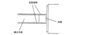
- a sheet-like reflecting member is sandwiched from above and below the light guide plate as shown in FIG. And by making this reflective member approach the board
- the light source when a substrate on which a plurality of LED elements are arranged is used as a light source, the light source is fixed by screwing to a metal member. Thereby, the heat generated when the light source emits light can be efficiently transferred to the outside or radiated.
- the reflective member When installing a reflective member with respect to a light source fixed with screws, the reflective member is slid toward the light source and brought close to the substrate. Thereby, the space between the incident surface of the light guide plate and the light source can be surrounded by the reflecting member without any gap.
- the reflecting member when the reflecting member is installed in the lighting device as shown in FIG. 9, it is difficult to surround the space between the incident surface of the light guide plate and the light source without any gap.
- the light source is arranged so that the substrate stands in a polygonal shape, and the LED element emits light to the outside of the polygonal shape.
- the light-guide plate is cyclic
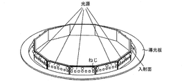
- the reflection member when the reflection member is installed in a configuration in which the light sources are arranged in a polygonal shape and the incident surface (light incident portion) of the light guide plate is provided on the inner periphery of the ring-shaped light guide plate, The reflection member interferes with a screw for fixing the light source. For this reason, it is impossible to install the reflecting member in a state in which it is close to the substrate.
- the present invention has been made in view of the above problems, and includes an illumination module capable of installing a reflecting member without causing light leakage even when a light source is fixed with screws.
- the purpose is to realize a lighting device.
- An illumination module communicates with an annular light guide member having a first opening, a light source having a light emitting element that emits light to an inner peripheral surface of the light guide member, and the first opening.
- An annular reflecting member that is stacked on the light guide member and covers a space between the light emitting element and the inner peripheral surface, and includes at least a stacking direction of the reflecting member.
- a fixing member for fixing the light source is provided so as to protrude from the light source so that the light emitting element faces the inner peripheral surface, and the inner surface of the reflecting member is provided.
- a slit is formed so as to extend in the outer circumferential direction and sandwich the fixing member when viewed from the stacking direction.
- the reflecting member can be installed without causing light leakage.
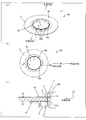
- FIG. 1 The structure of the illumination module of one Embodiment of this invention is shown, (a) is a perspective view, (b) is a front view, (c) shows the internal structure of an illumination module, X of (b) FIG. It is a top view which shows the structure of the light source shown in FIG. (A)-(c) is a perspective view which shows an example of the procedure in the assembly method of an illumination module. It is sectional drawing which shows typically operation
- the structure of the illumination module of other embodiment of this invention is shown, (a) is a perspective view, (b) is a front view. It is sectional drawing which shows the outer periphery shape of the light guide means with which the illumination module of FIG. 6 was equipped. It is sectional drawing which shows the example of 1 structure of the conventional illumination module which uses the member by which the several LED element was linearly arranged on one board
- FIG. 1 shows a configuration of an illumination module 100 according to the present embodiment, where FIG. 1A is a perspective view, FIG. 1B is a front view, and FIG. 1C is an illumination module.
- FIG. 2 is a cross-sectional view taken along the line XX of FIG.
- the same reference numerals represent the same or corresponding parts.
- the illumination module 100 includes a light source 1, a light guide unit 2 (light guide member) that guides light emitted from the light source 1, and the light source 1 and the light guide unit 2.
- a light guide unit 2 light guide member
- the reflection members 41 and 42 are disposed so as to cover the space (light coupling portion) between the light source 1 and the light guide means 2.
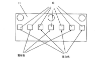
- FIG. 2 is a top view showing the configuration of the light source 1.
- the light source 1 includes at least one light emitting element 12 and a substrate 11 on which the light emitting element 12 is mounted.
- the light source 1 is controlled by a light source control means (lighting means) (not shown), and output adjustment of the emitted light from the light source 1 is possible.
- the “illumination device” in the present invention means an apparatus including the illumination module 100 shown in FIG. 1 and the like and light source control means for controlling lighting of the light source 1 in the illumination module 100.
- the light emitting element 12 when the light emitting element 12 is composed of a plurality of light emitting elements having different light emission colors such as daylight white and light bulb color, the light output of each light emitting element is controlled by the light source control means. This makes it possible to adjust the color of the light emitted from the light source 1.
- the light emitted from the light source 1 is daylight white.
- the emitted light from the light source 1 will become a light bulb color.
- the color tone of the light emitted from the light source 1 can be changed by simultaneously turning on the daylight white light emitting element and the light emitting element of the light bulb color and adjusting the ratio of the amount of light of each color.
- the plurality of light sources 1 are arranged so that the substrate 11 is erected in a dodecagonal shape, and the light emitting element 12 emits light toward the outside of the dodecagonal shape.
- the light source 1 is disposed so as to face the incident surface 21 of the light guide means 2. Light emitted from the light source 1 enters the incident surface 21 of the light guide unit 2 and is guided through the light guide unit 2 by repeating total reflection.
- the light guide means 2 is a plate-like member made of a material having translucency.
- the material of the light guide means 2 is an acrylic resin.
- the light guide means 2 has an incident surface 21 on which the outgoing light from the light source 1 is incident, and outgoing surfaces 22 and 23 that emit the light guided inside to the outside.
- a diffusion portion (not shown) is formed on at least one of the emission surfaces 22 and 23.
- This diffusing unit has a function of diffusing light guided inside the light guide means 2 and is configured by diffusing dots, prisms, microlenses, and the like. Further, the diffusing portion can be formed into a pattern of diffusing dots by printing the light diffusing material such as screen printing.
- the outgoing light from the light source 1 is diffused when it is guided through the light guide means 2 and incident on the diffusion portion.
- the light diffused by the diffusing unit is incident on the exit surface 22 or 23.
- the component that has entered the exit surface 22 or 23 at an angle that does not satisfy the total reflection condition (the total reflection condition is broken) is emitted from the exit surface 22 or 23 to the outside. Will do.
- a component incident on the emission surface 22 or 23 at an angle satisfying the total reflection condition is guided by the light guide means 2 while being totally reflected by the emission surface 22 or 23.
- the illumination module 100 can realize surface-emitting illumination and functions as an illumination device.
- the material of the light guide means 2 is not limited to acrylic resin, and may be any material as long as it has translucency and can extract light that guides the inside from the exit surface.
- PC polycarbonate
- PS polystyrene
- the light guide means 2 may be constituted by a member in which a diffusing agent that diffuses light is added to a light-transmitting material.
- a diffusing agent that diffuses light is added to a light-transmitting material.
- each light source 1 is fixed to the base 3 by a fixing component 5 (fixing member) such as a screw.
- the material of the base 3 is preferably a metal such as aluminum.
- the light guide means 2 has an opening (not shown; a first opening), and a plurality of light sources 1 fixed in a dodecagonal shape enter the opening.
- the side wall surface constituting the opening is an incident surface 21 (first inner peripheral surface) on which light emitted from the light source 1 is incident. Therefore, the side wall constituting the opening of the light guide means 2 has a dodecagonal shape.
- the side wall surface (incident surface 21) corresponding to each side of the dodecagonal shape faces each side of the dodecagonal shape (that is, each light source 1) formed by the plurality of light sources 1.
- the light guide means 2 has an annular shape having an opening in the center, and the inner peripheral surface thereof is opposed to the light emitting element 12 and becomes an incident surface 21 on which light emitted from the light source 1 is incident. Yes.
- the light emitted from the light source 1 is emitted at a spread angle. Therefore, light having a relatively small exit angle is incident on the incident surface 21 of the light guide unit 2, while light having a relatively large exit angle is not incident on the incident surface 21 of the light guide unit 2 and is removed. . For this reason, a loss related to optical coupling occurs.
- the reflection members 41 and 42 are members for reducing this loss, and are disposed so as to cover the space A (light coupling portion) between the light source 1 and the incident surface 21 of the light guide means 2.
- the arrangement of the reflecting members 41 and 42 is preferably such that the end surfaces of the reflecting members 41 and 42 are brought close to the substrate 11 to completely cover the periphery of the light emitting element 12.
- the reflecting members 41 and 42 have an opening (not shown; second opening) communicating with the opening of the light guide means 2.
- the inner periphery that forms the opening of the reflecting members 41 and 42 has a dodecagonal shape so as to correspond to the opening of the light guide means 2.
- the reflecting member 41, the light guide means 2, and the reflecting member 42 are laminated in this order.
- the stacking direction of the reflecting member 41, the light guide unit 2, and the reflecting member 42 is defined as the Z direction.
- “upper side” means the reflection member 42 side when the light guide means 2 is used as a reference
- “lower side” means the reflection member 41 side. In the lighting device shown in FIG. 5 described later, “lower side” refers to the floor surface side, and “upper side” refers to the ceiling side.
- the inner peripheral surfaces 41a and 42a of the reflecting members 41 and 42 are close to the substrate 11 of the light source 1, respectively.
- the reflecting members 41 and 42 cover the light emitting element 12 from both the upper and lower sides in the Z direction.
- the light source 1 and the illumination module 100 include the annular light guide means 2 having an opening, and the annular reflecting members 41 and 42 having openings that communicate with the opening of the light guide 2. ing.
- the light source 1 includes a light emitting element 12 that emits light to an incident surface 21 that is an inner peripheral surface of the light guide unit 2.
- the reflecting members 41 and 42 are stacked on the light guide unit 2 to cover the space A between the light emitting element 12 and the incident surface 21.
- the fixed component 5 protrudes from the light source 1 in the outer circumferential direction on the upper side (the reflective member 42 side) in the stacking direction (Z direction) of the reflective members 41 and 42. Is provided.
- the fixing component 5 fixes the light source 1 to the base 3 as a base material so that the light emitting element 12 faces the incident surface 21.
- the slit 42 b extends from the inner peripheral surface 42 a (second inner peripheral surface) of the reflecting member 42 in the outer peripheral direction. And it sees from a Z direction (refer (b) of FIG. 1), and it forms so that the fixing component 5 may be pinched
- the inner peripheral portion 42c of the reflecting member 42 adjacent to the light source 1 is flexible in the Z direction. Therefore, even when the light source 1 is fixed by the fixing component 5, it is possible to install the reflecting member 42 on the light guide unit 2 from the upper side in the Z direction without causing light leakage.
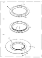
- FIGS. 3A to 3C are perspective views showing an example of a procedure in the method for assembling the illumination module 100.
- FIG. 3A to 3C are perspective views showing an example of a procedure in the method for assembling the illumination module 100.
- a reflecting member 41 is installed on the base 3.
- the base 3 has a cylindrical portion 3A having a dodecagonal prism.
- the light source 1 is fixed to the outer periphery of the cylindrical portion 3A.
- the reflective member 41 is installed on the base 3 by inserting the cylindrical portion 3 ⁇ / b> A into the opening of the reflective member 41. At this time, the inner peripheral surface 41a of the reflecting member 41 is in a state close to the outer periphery of the cylindrical portion 3A.
- the light source 1 is fixed to the outer periphery of the cylindrical portion 3 ⁇ / b> A in the base 3 by the fixing component 5.
- the light guiding means 2 is installed from the upper side in the Z direction in the configuration shown in FIG.
- the light guide unit 2 is installed so that the incident surface 21 (inner peripheral surface) faces the light emitting element 12 of the light source 1.
- the light guide means 2 is installed so that each corner of the dodecagon formed by the light source 1 corresponds to each corner of the dodecagon formed by the incident surface 21 when viewed from above in the Z direction.
- the reflecting member 42 is laminated on the light guide means 2 from the upper side in the Z direction.
- the reflection member 42 is installed so that each corner portion of the inner peripheral surface 42 a having a dodecagon shape matches with each corner portion of the dodecagon shape formed by the light source 1 when viewed from the upper side in the Z direction.
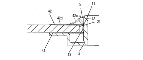
- FIG. 4 is a cross-sectional view schematically showing the operation of the inner peripheral portion 42c adjacent to the light source 1 when the reflecting member 42 is installed on the light guide means 2 from the upper side in the Z direction. Since the slits 42b are formed at the respective corners of the dodecagonal inner peripheral surface 42a, the inner peripheral part 42c of the reflecting member 42 adjacent to the light source 1 is flexible in the Z direction.
- the reflecting member 42 When the reflecting member 42 is installed on the light guide unit 2 from the upper side in the Z direction, the reflecting member 42 and the fixed component 5 interfere with each other.
- the inner peripheral portion 42 c of the reflecting member 42 When interfering with the fixed component 5, the inner peripheral portion 42 c of the reflecting member 42 is in contact with the fixed component 5 in a bent state and is not in contact with the light guide means 2.
- the outer peripheral portion 42 d of the reflecting member 42 is in contact with the light guide means 2.
- a restoring force directed downward in the Z direction acts on the inner peripheral portion 42c of the reflecting member 42 so as to be at the same level as the outer peripheral portion 42d.
- the inner peripheral part 42c slides the fixed component 5, and is arrange
- the reflecting member 42 avoids the fixed component 5 and covers the light emitting element 12 from the upper side in the Z direction.
- the configuration of the finally assembled lighting module 100 is shown in FIG. As shown in (c) of FIG. 3, the reflecting member 42 is disposed below the fixed component 5 in the Z direction. The light emitting element 12 of the light source 1 is covered by the reflecting member 42, while the fixing component 5 that fixes the light source 1 is exposed to the outside of the reflecting member 42 without being covered by the reflecting member 42.
- the reflection member 42 when the reflection member 42 is provided with a relief portion for the fixed component 5, the reflection member 42 can be installed from the upper side in the Z direction without interfering with the fixed component 5. .
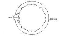
- the light emitting element 12 is not covered (exposed) by the reflecting member 42 at the place where the relief portion is provided. For this reason, all the components emitted in the direction of the escape portion in the emitted light of the light emitting element 12 are lost. As a result, light utilization efficiency is reduced.
- the reflecting member 42 extends from the inner peripheral surface 42a to the outer peripheral direction and is viewed from the Z direction ((b) in FIG. 1). And the fixing part 5 is sandwiched between them. For this reason, even if the reflecting member 42 is installed from the upper side in the Z direction, the fixed component 5 can be avoided and the light emitting element 12 can be covered from the upper side in the Z direction. As a result, even when the light source 1 is fixed by the fixing component 5, it is possible to cover the light emitting element 12 from both the upper side in the Z direction and the lower side in the Z direction, so that the light use efficiency is not reduced. .
- the lighting device of the present embodiment includes a lighting module 100 and a light source control unit that controls lighting of the light source 1 in the lighting module 100.
- FIG. 5 is a perspective view showing an example of such an illumination device.
- the illuminating device of this embodiment is not limited to the structure shown by FIG.
- the lighting device shown in FIG. 5 includes a lighting module 100 and an upper housing 101.
- the upper housing part 101 is installed on the ceiling.
- Housed in the upper housing 101 is a light source control means for controlling lighting of the light source 1 in the illumination module 100, and a power supply unit. Further, the light source control means and the power supply unit housed in the upper housing unit 101 are connected to the illumination module 100 via the wiring 103.
- a wire 102 is interposed between the illumination module 100 and the upper housing part 101. An end on the ceiling side (upper side) of the wire 102 is fixed to the upper housing part 101, and an end on the floor side (lower side) of the wire 102 is fixed to the lighting module 100.
- the illumination module 100 is in a state of being hung by a wire 102 from an upper housing part 101 fixed to the ceiling.
- FIG. 6A and 6B show a configuration of the illumination module 200 of the present embodiment, in which FIG. 6A is a perspective view and FIG. 6B is a front view.
- FIG. 6A is a perspective view
- FIG. 6B is a front view.
- members having the same functions as those in the drawings explained in the first embodiment are given the same reference numerals and explanations thereof are omitted.
- the outer peripheral surface of the light guide means 2 is inclined, and a reflective layer is provided on the outer peripheral surface. Different from the illumination module 100 of the first embodiment.
- the outer peripheral shape of the light guide means 2 will be described in detail.
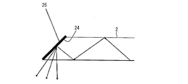
- FIG. 7 is a cross-sectional view showing the outer peripheral shape of the light guide means 2.
- FIG. 7 also shows an optical path of light guided through the light guide unit 2.
- the outer peripheral surface 24 of the light guide means 2 is inclined so as to become wider from the upper side to the lower side in the Z direction.
- a reflective layer 25 is provided on the outer peripheral surface 24 of the light guide means 2.
- the light emitted from the light emitting element 12 travels while totally reflecting the inside of the light guide means 2, and is emitted by the above-described diffusion part (for example, a diffusion pattern) or the added diffusion agent.
- the light exits from the surfaces 22 and 23.
- the component that does not enter the diffusing portion or the diffusing agent repeats total reflection and finally reaches the outer peripheral surface 24 of the light guide means 2.
- the outer peripheral surface 24 of the light guide means 2 is inclined so as to become wider from the upper side to the lower side in the Z direction, and the outer peripheral surface 24 is reflected by Since the layer 25 is provided, the light that has reached the outer peripheral surface 24 is reflected by the reflective layer 25 and is emitted from the emission surface 22 to the outside.
- the illumination module 200 uses the light emitted from the emission surfaces 22 and 23 as illumination light.
- the outer peripheral surface 24 an inclined surface and providing the reflective layer 25 on the outer peripheral surface 24, it is possible to extract light reflected from the reflective layer 25 from the emission surface 22. As a result, the illumination intensity of the lighting module can be increased.
- the reflecting member 42 extends from the inner peripheral surface 42a to the outer peripheral direction and is seen from the Z direction (see FIG. 1B), and the fixed component 5 It is formed so as to sandwich. For this reason, even if the reflecting member 42 is installed from the upper side in the Z direction, the fixed component 5 can be avoided and the light emitting element 12 can be covered from the upper side in the Z direction. As a result, even when the light source 1 is fixed by the fixing component 5, it is possible to cover the light emitting element 12 from both the upper side in the Z direction and the lower side in the Z direction, so that the light use efficiency is not reduced. . Therefore, an illumination module with high light utilization efficiency can be realized.
- the lighting module of the present invention on an electronic device such as a lighting device, a lighting device with high light utilization efficiency can be realized.
- the light emitting element 12 may be any light source that can couple light to the light guide means 2, and examples thereof include an LED and an organic EL.
- the arrangement of the light source 1, the shape of the inner peripheral surface (incident surface 21) that forms the opening of the light guiding means 2, and the inner peripheral surface 42 a that forms the opening of the reflecting member 42 is a dodecagon.
- these shapes are not limited to a dodecagon, and may be a polygon that is a triangle or more.
- a light source composed of at least one light emitting element, a base that holds the light source in a polygonal shape, a fixing component that fixes the light source to the base, and guides light from the light source.
- An illumination device having a light guide means and a reflective member that covers a coupling portion between the light source and the light guide means, wherein the reflective member has a polygonal opening having the same number of angles as the light source held by the base And a slit is provided at a corner of the polygonal opening.
- An illumination device including the illumination module according to any one of [1] and [2] and a lighting unit that turns on the light source.
- an illumination module of the present invention includes an annular light guide member having a first opening, and a light source having a light emitting element that emits light to the inner peripheral surface of the light guide member.
- An annular reflecting member having a second opening communicating with the first opening and covering the space between the light emitting element and the inner peripheral surface by being stacked on the light guide member.
- a fixing member for fixing the light source is provided on at least one side in the stacking direction of the reflecting member so as to protrude from the light source in the outer peripheral direction so that the light emitting element faces the inner peripheral surface.
- the reflective member is characterized in that a slit is formed so as to extend from the inner peripheral surface to the outer peripheral direction and sandwich the fixing member when viewed from the stacking direction.
- a light guide member is an annular member which has a 1st opening part
- a reflection member is an annular member which has a 2nd opening part connected with the said 1st opening part.
- the reflection member is disposed so as to be stacked on the light guide member and cover a space between the light emitting element and the inner peripheral surface of the light guide member.
- a fixing member for fixing the light source is provided on at least one side in the stacking direction of the reflecting member so as to protrude from the light source in the outer peripheral direction so that the light emitting element faces the inner peripheral surface.
- the fixing member protrudes from the light source in the outer circumferential direction. Therefore, when the reflecting member is installed on the light guide member from the upper side in the stacking direction, the fixing member and the reflecting member interfere with each other. End up.
- the slit is formed in the reflecting member so as to extend from the inner circumferential surface to the outer circumferential direction and sandwich the fixing member when viewed from the stacking direction, the reflecting member is close to the light source in the reflecting member.
- the inner peripheral portion is flexible in the stacking direction.
- the reflecting member avoids the fixing member and covers the light emitting element from the upper side in the stacking direction.
- a member can be installed.
- the illumination module which can install a reflection member, without producing light leakage is realizable.
- the shape of the first inner peripheral surface constituting the first opening, the shape of the second inner peripheral surface constituting the second opening, and the first inner periphery It is preferable that the shapes formed by the light sources facing the surface are both polygonal, and the slits are provided to extend from each corner of the polygon formed by the second inner peripheral surface.
- the light from the light source can be uniformly guided in the outer circumferential direction of the light guide member, and the reflecting member can be installed without causing light leakage even when the light source is screwed and fixed. it can.
- the outer peripheral surface of the light guide member is an inclined surface that is inclined so as to become wider from the upper side to the lower side in the stacking direction, and a reflective layer is formed on the outer peripheral surface. It is preferable to be provided.
- the outer peripheral surface of the said light guide member becomes an inclined surface inclined so that it may become wide toward the lower side from the upper side in the said lamination direction, and a reflection layer is in the said outer peripheral surface. Since it is provided, the component which reaches
- the light source includes a substrate on which the light emitting element is mounted, and a base material for holding the light source is made of metal.
- an illumination device includes the above-described illumination module and lighting means for lighting the light source.
- the illumination module of the present invention includes an annular light guide member having a first opening, a light source having a light emitting element that emits light to the inner peripheral surface of the light guide member, and the first light source.
- An annular reflection member that has a second opening that communicates with the opening, and is laminated on the light guide member to cover a space between the light emitting element and the inner peripheral surface, and the reflection member
- a fixing member for fixing the light source is provided so as to protrude from the light source in the outer peripheral direction so that the light emitting element faces the inner peripheral surface on at least one side in the stacking direction. Is a configuration in which a slit is formed so as to extend from the inner peripheral surface in the outer peripheral direction and sandwich the fixing member when viewed from the stacking direction.
- the illumination device of the present invention has the configuration including the illumination module and the lighting means for lighting the light source.
- the lighting module of the present invention and the lighting device including the lighting module can be applied to lighting devices in general such as a lighting device that is suspended from a ceiling and a lighting device that is placed on a desk. And as an application field, it can apply to various lighting fixtures, such as facilities, such as a store and an office, and business.
Landscapes
- Physics & Mathematics (AREA)
- General Physics & Mathematics (AREA)
- Optics & Photonics (AREA)
- Engineering & Computer Science (AREA)
- General Engineering & Computer Science (AREA)
- Non-Portable Lighting Devices Or Systems Thereof (AREA)
- Planar Illumination Modules (AREA)
Abstract
照明モジュールの組立てに際し、光源がねじ止め固定されている場合でも、光漏れを発生させることが無い反射部材の設置を実現することを目的とし、本発明の照明モジュールにおける反射部材(42)には、内周面(42a)から外周方向へ延び、Z方向から見て固定部品(5)を挟むようにスリット(42b)が形成されている。
Description
本発明は、室内照明として使用される照明モジュールに関し、更に詳しくは、光源と導光板からなり、前記光源からの光が導光板を通して発光面から出射する照明モジュール、及びこれを用いた照明装置に関する。
近年、導光板を利用した薄型の照明装置が種々提案されている。導光板を利用した照明装置では、導光板の入射面から入射した光を、導光板の対向面間の全反射により伝播させ、上記伝播光を拡散反射層や凹凸パターンにより導光板外部に出射させている。これによって、照明装置として機能する。
導光板を利用した照明装置の技術としては、例えば特許文献1に開示された技術が挙げられる。特許文献1の照明装置では、光源から出射される光を効率よく導光板の入射面に入射させるために、光源の光出射部と導光板の入射面との間の空間を囲むように、反射シート等の反射部材が設けられている。これによって、導光板の入射面以外の部分に光源からの出射光が漏れることを防止することができる。その結果、光源からの出射光を有効利用することができる。
また、特許文献2には、発光光源と対向する入射側面に、開口部を構成する側壁面が略四角形であり、かつ底部に円弧状(円筒状)の角部を有する盲孔(窪み)が1個または複数設けられた導光板が開示されている。
導光板の入射面以外の部分に光が漏れることを防止し、効率的に入射面に入光させるためには、光源及び導光板の入光部の両方と反射部材との隙間を無くして、光源と入射面との間の空間を全体的に反射部材で囲むことが望ましい。
例えば、複数のLED素子が1つの基板上に直線状に配列された部材を光源として使用する場合、図8に示されるように、シート状の反射部材を導光板の上下方向から挟む。そして、この反射部材を、複数のLED素子が配列された基板に接近させることによって、導光板の入射面と光源との間の空間を隙間なく反射部材で囲むことができる。
また、一般的に、複数のLED素子が配列された基板を光源として使用する場合、光源は、金属部材に対してねじ止め固定されている。これによって、光源が発光する際に発生する熱を効率よく外部へ伝熱する、あるいは放熱することができる。
ねじ固定された光源に対して反射部材を設置する場合、反射部材を光源側にスライドさせ、基板に対して接近させる。これによって、導光板の入射面と光源との間の空間を隙間なく反射部材で囲むことができる。
しかし、図9に示されるような照明装置に反射部材を設置する場合、導光板の入射面と光源との間の空間を隙間なく反射部材で囲むことが困難である。図9に示される照明装置において、光源は、基板が多角形形状を成して立設するように配置され、LED素子は、該多角形形状の外側へ光を出射する。そして、導光板は、環状になっており、この環形状の内周面が、光源からの光の入射面(入光部)となっている。
図9に示されるように、光源が多角形形状に配置され、導光板の入射面(入光部)がリング状の導光板の内周に設けられている構成に反射部材を設置する場合、反射部材が、光源を固定するねじと干渉してしまう。このため、反射部材を基板と接近させた状態で設置することができない。
また、図10に示されるように、反射部材におけるねじとの干渉部分に逃げを設けることによって、反射部材とねじとの干渉を回避することは可能である。しかし、この場合、逃げの部分が隙間となり、そこから光漏れが生じ、光利用効率が悪化する。
本発明は、上記の課題を鑑みてなされたものであり、光源がねじ止め固定されている場合でも、光漏れを発生させること無く反射部材を設置することが可能な照明モジュール、及びそれを備えた照明装置を実現することを目的とする。
本発明の照明モジュールは、第1の開口部を有する環状の導光部材と、上記導光部材の内周面に対し光を出射する発光素子を有する光源と、上記第1の開口部と連通する第2の開口部を有し、上記導光部材に積層して上記発光素子と上記内周面との間の空間を覆う環状の反射部材と、を備え、上記反射部材における積層方向の少なくとも一方の側には、上記発光素子が上記内周面と対向するように上記光源を固定する固定部材が、上記光源から外周方向へ突出して設けられており、上記反射部材には、内周面から外周方向へ延び、上記積層方向から見て上記固定部材を挟むようにスリットが形成されていることを特徴としている。
本発明によれば、光源がねじ止め固定されている場合でも、光漏れを発生させること無く反射部材を設置することができるという効果を奏する。
〔実施の形態1〕
本発明の一実施形態について図1~図4に基づいて説明すれば、以下のとおりである。図1は、本実施形態の照明モジュール100の構成を示し、図1の(a)は斜視図であり、図1の(b)は正面図であり、図1の(c)は、照明モジュール100の内部構造を示し、図1(b)のX-X断面図である。なお、本発明の図面において、同一の参照符号は、同一部分または相当部分を表すものとする。
本発明の一実施形態について図1~図4に基づいて説明すれば、以下のとおりである。図1は、本実施形態の照明モジュール100の構成を示し、図1の(a)は斜視図であり、図1の(b)は正面図であり、図1の(c)は、照明モジュール100の内部構造を示し、図1(b)のX-X断面図である。なお、本発明の図面において、同一の参照符号は、同一部分または相当部分を表すものとする。
(照明モジュールの構成)
本実施形態の照明モジュール100は、図1に示されるように、光源1と、光源1から出射された光を導光する導光手段2(導光部材)と、光源1及び導光手段2を保持するベース3(基材)と、反射部材41・42とを備えている。反射部材41・42は、光源1と導光手段2との間の空間(光結合部)を覆うように配置されている。
本実施形態の照明モジュール100は、図1に示されるように、光源1と、光源1から出射された光を導光する導光手段2(導光部材)と、光源1及び導光手段2を保持するベース3(基材)と、反射部材41・42とを備えている。反射部材41・42は、光源1と導光手段2との間の空間(光結合部)を覆うように配置されている。
(光源1及び導光手段2)
図2は、光源1の構成を示す上面図である。図2に示されるように、光源1は、少なくとも1つの発光素子12と、発光素子12を実装するための基板11とを備えている。なお、光源1は、図示しない光源制御手段(点灯手段)によって制御されており、光源1からの出射光の出力調整が可能になっている。なお、本発明でいう「照明装置」とは、図1等に示す照明モジュール100と、照明モジュール100における光源1の点灯を制御する光源制御手段とを備えた装置を意味する。
図2は、光源1の構成を示す上面図である。図2に示されるように、光源1は、少なくとも1つの発光素子12と、発光素子12を実装するための基板11とを備えている。なお、光源1は、図示しない光源制御手段(点灯手段)によって制御されており、光源1からの出射光の出力調整が可能になっている。なお、本発明でいう「照明装置」とは、図1等に示す照明モジュール100と、照明モジュール100における光源1の点灯を制御する光源制御手段とを備えた装置を意味する。
また、図2に示されるように、発光素子12を、例えば昼白色、電球色等といった発光色が異なる複数の発光素子で構成した場合、個々の発光素子の光出力を光源制御手段によって制御することにより、光源1からの出射光の色調整を行うことが可能になる。
例えば、昼白色の発光素子のみが点灯するように制御すれば、光源1からの出射光は昼白色となる。また、電球色の発光素子のみが点灯するように制御すれば、光源1からの出射光は電球色となる。また、昼白色の発光素子と電球色の発光素子とを同時に点灯し、各色の光量の割合を調整することによって、光源1からの出射光の色調を変化させることが可能になる。
複数の光源1は、基板11が12角形形状を成して立設するように配置され、発光素子12は、12角形形状の外側へ向かって光を出射するようになっている。
光源1は、導光手段2の入射面21に対して対向するように配置されている。光源1からの出射光は、導光手段2の入射面21に入光し、全反射を繰り返して導光手段2内部を導光する。
(導光手段2について)
導光手段2は、透光性を有する材料からなる板状の部材である。導光手段2の材料は、アクリル樹脂である。導光手段2は、光源1からの出射光を入射する入射面21と、内部で導光している光を外部へ出射する出射面22・23を有している。出射面22・23の少なくとも一方の面には、図示しない拡散部が形成されている。この拡散部は、導光手段2内部を導光する光を拡散する機能を有し、拡散ドット、プリズム、マイクロレンズ等で構成されている。また、拡散部は、光拡散材料をスクリーン印刷等の印刷することによって、拡散ドットのパターンとすることができる。
導光手段2は、透光性を有する材料からなる板状の部材である。導光手段2の材料は、アクリル樹脂である。導光手段2は、光源1からの出射光を入射する入射面21と、内部で導光している光を外部へ出射する出射面22・23を有している。出射面22・23の少なくとも一方の面には、図示しない拡散部が形成されている。この拡散部は、導光手段2内部を導光する光を拡散する機能を有し、拡散ドット、プリズム、マイクロレンズ等で構成されている。また、拡散部は、光拡散材料をスクリーン印刷等の印刷することによって、拡散ドットのパターンとすることができる。
光源1からの出射光は、導光手段2の内部を導光し拡散部に入射すると、拡散する。拡散部にて拡散した光は、出射面22または23に入射する。このとき、拡散部にて拡散した光のうち、出射面22または23に対し全反射条件を満たさない角度で入射した(全反射条件が崩れた)成分は、出射面22または23から外部へ出射することになる。また、出射面22または23に対し全反射条件を満たす角度で入射した成分は、出射面22または23で全反射しつつ、導光手段2内部を導光する。このように、導光手段2の内部を導光する光は、拡散部の作用によって、全反射して伝搬しつつ、出射面22または23から外部へ出射する。その結果、照明モジュール100は、面発光照明を実現することができ、照明装置としての機能を果たす。
なお、導光手段2の材料は、アクリル樹脂に限定されず、透光性を有し内部を導光する光を出射面から取り出すことが可能な材料であればよく、例えば、PC(ポリカーボネート)、PS(ポリスチレン)等が挙げられる。
また、導光手段2は、透光性を有する材料に、光を拡散する拡散剤が添加された部材で構成されていてもよい。導光手段2内部を導光する光は、添加された拡散剤に入射すると、上述の拡散部に入射した場合と同様に、出射面22または23から外部へ出射する成分と、出射面22または23で全反射する成分とに分かれる。その結果、照明モジュール100は、面発光照明を実現することができ、照明装置としての機能を果たす。
(光源1の配置及び光源1をベース3に固定する部材について)
複数の光源1は、図1の(a)及び(b)に示されるように、12角形形状を成すように立設して配置されている。個々の光源1は、ベース3に対して、例えばネジ等の固定部品5(固定部材)により固定されている。
複数の光源1は、図1の(a)及び(b)に示されるように、12角形形状を成すように立設して配置されている。個々の光源1は、ベース3に対して、例えばネジ等の固定部品5(固定部材)により固定されている。
光源1点灯時には、発光素子12(図2参照)が発熱する。それゆえ、発光素子12から発生する熱を効率よく伝熱する、あるいは放熱するために、ベース3の材料は、例えばアルミニウム等の金属であることが好ましい。
(導光手段2の入射面21)
導光手段2は、開口部(不図示;第1の開口部)を有し、該開口部に、12角形形状を成して固定された複数の光源1が入るようになっている。導光手段2においては、開口部を構成する側壁面が、光源1からの出射光を入射する入射面21(第1の内周面)となっている。それゆえ、導光手段2の開口部を構成する側壁は、12角形形状になっている。そして、12角形形状の各辺にあたる側壁面(入射面21)は、複数の光源1が構成する12角形形状の各辺(すなわち、個々の光源1)に対向する。換言すれば、導光手段2は、中央に開口部を有する環状になっており、その内周面は、発光素子12と対向し、光源1からの出射光を入射する入射面21となっている。
導光手段2は、開口部(不図示;第1の開口部)を有し、該開口部に、12角形形状を成して固定された複数の光源1が入るようになっている。導光手段2においては、開口部を構成する側壁面が、光源1からの出射光を入射する入射面21(第1の内周面)となっている。それゆえ、導光手段2の開口部を構成する側壁は、12角形形状になっている。そして、12角形形状の各辺にあたる側壁面(入射面21)は、複数の光源1が構成する12角形形状の各辺(すなわち、個々の光源1)に対向する。換言すれば、導光手段2は、中央に開口部を有する環状になっており、その内周面は、発光素子12と対向し、光源1からの出射光を入射する入射面21となっている。
光源1の出射光は、入射面21に入射し、入射面21から外周方向に導光し、上述した拡散部または拡散剤の作用によって、出射面22・23から出射する。
(光源1と導光手段2との間の空間A(光結合部)について)
光源1からの出射光は、広がり角で出射する。そのため、出射角度が相対的に小さい光は、導光手段2の入射面21に入射する一方、出射角度が相対的に大きい光は、導光手段2の入射面21に入射せず外れてしまう。このため、光結合に関する損失が発生する。
光源1からの出射光は、広がり角で出射する。そのため、出射角度が相対的に小さい光は、導光手段2の入射面21に入射する一方、出射角度が相対的に大きい光は、導光手段2の入射面21に入射せず外れてしまう。このため、光結合に関する損失が発生する。
反射部材41・42は、この損失を低減するための部材であり、光源1と導光手段2の入射面21との間の空間A(光結合部)を覆うように配置されている。これによって、光源1からの出射光のうち、出射角度が相対的に大きく導光手段2の入射面21から外れてしまう光は、反射部材41・42により反射する。そして、この反射光の一部は、入射面21に入射するため、光結合に関する損失を低減することが可能になる。
反射部材41・42の配置は、反射部材41・42の端面を基板11に接近させ、発光素子12の周囲を完全に覆う形とすることが好ましい。
(反射部材41・42の構造)
また、反射部材41・42は、導光手段2の開口部と連通する開口部(不図示;第2の開口部)を有する。反射部材41・42の開口部を形成する内周は、導光手段2の開口部に対応するように、12角形形状になっている。また、図1の(c)に示されるように、反射部材41、導光手段2、及び反射部材42は、この順に積層されている。以下の説明では、反射部材41、導光手段2、及び反射部材42の積層方向をZ方向とする。また、「上側」とは、導光手段2を基準とした場合、反射部材42側と意味し、「下側」とは、反射部材41側を意味する。また、後述する図5に示された照明装置においては、「下側」とは、床面側をいい、「上側」とは、天井側をいう。
また、反射部材41・42は、導光手段2の開口部と連通する開口部(不図示;第2の開口部)を有する。反射部材41・42の開口部を形成する内周は、導光手段2の開口部に対応するように、12角形形状になっている。また、図1の(c)に示されるように、反射部材41、導光手段2、及び反射部材42は、この順に積層されている。以下の説明では、反射部材41、導光手段2、及び反射部材42の積層方向をZ方向とする。また、「上側」とは、導光手段2を基準とした場合、反射部材42側と意味し、「下側」とは、反射部材41側を意味する。また、後述する図5に示された照明装置においては、「下側」とは、床面側をいい、「上側」とは、天井側をいう。
反射部材41・42の内周面41a・42aはそれぞれ、光源1の基板11に近接している。そして、反射部材41・42は、発光素子12をZ方向の上側及び下側の両側から覆うようになっている。
以上のように、光源1と、照明モジュール100は、開口部を有する環状の導光手段2と、導光手段2の開口部と連通する開口部を有する環状の反射部材41・42とを備えている。光源1は、導光手段2の内周面である入射面21に対し光を出射する発光素子12を有している。また、反射部材41・42はそれぞれ、導光手段2に積層して、発光素子12と入射面21との間の空間Aを覆っている。
また、図1の(c)に示されるように、反射部材41・42における積層方向(Z方向)の上側(反射部材42側)には、固定部品5が、光源1から外周方向に突出して設けられている。この固定部品5は、発光素子12が入射面21と対向するように、光源1を基材としてのベース3に固定する。
(照明モジュール100の特徴的構成)
照明モジュール100は、発光素子12における固定部品5側から覆う反射部材42に少なくとも2つのスリット42bが形成されている。このスリット42bは、図1の(b)及び(c)を見てわかるように、反射部材42の内周面42a(第2の内周面)から外周方向へ延びている。そして、Z方向から見て(図1の(b)参照)、固定部品5を挟むように形成されている。より具体的には、スリット42bは、反射部材42の開口部を形成する12角形形状の内周面42aの各角部から外周方向に延びるように形成されている。そして、Z方向から見て、光源1を固定する固定部品5が、2つのスリット42bの間に配されるようになっている。
照明モジュール100は、発光素子12における固定部品5側から覆う反射部材42に少なくとも2つのスリット42bが形成されている。このスリット42bは、図1の(b)及び(c)を見てわかるように、反射部材42の内周面42a(第2の内周面)から外周方向へ延びている。そして、Z方向から見て(図1の(b)参照)、固定部品5を挟むように形成されている。より具体的には、スリット42bは、反射部材42の開口部を形成する12角形形状の内周面42aの各角部から外周方向に延びるように形成されている。そして、Z方向から見て、光源1を固定する固定部品5が、2つのスリット42bの間に配されるようになっている。
このようにスリット42bが形成されているので、反射部材42における光源1に近接する内周部42cは、Z方向に可撓する。よって、光源1が固定部品5によって固定されている場合でも、光漏れを発生させること無く、Z方向上側から反射部材42を導光手段2に設置することが可能になる。
ここで、照明モジュール100の組立方法の手順の一例について、説明する。図3の(a)~(c)は、照明モジュール100の組立方法における手順の一例を示す斜視図である。
まず、図3の(a)に示されるように、ベース3に反射部材41を設置する。ベース3は、12角柱の筒状部3Aを有している。光源1は、筒状部3Aの外周に固定される。反射部材41の開口部に筒状部3Aを挿入することによって、ベース3に反射部材41を設置する。このとき、反射部材41の内周面41aは、筒状部3Aの外周に近接した状態になっている。
次に、図3の(b)に示されるように、ベース3における筒状部3Aの外周に光源1を固定部品5によって固定する。
そして、次に、図3の(b)に示された構成にZ方向上側から導光手段2を設置する。このとき、入射面21(内周面)が光源1の発光素子12と対向するように、導光手段2を設置する。換言すれば、Z方向上側から見て、光源1が成す12角形形状の各角部が、入射面21が構成する12角形形状の各角部に対応するように、導光手段2を設置する。次いで、Z方向上側から反射部材42を導光手段2に積層して配置する。このとき、Z方向上側から見て、12角形形状の内周面42aの各角部が、光源1が構成する12角形形状の各角部に適合するように、反射部材42を設置する。
図4は、Z方向上側から反射部材42を導光手段2に設置するときの、光源1に近接する内周部42cの動作を模式的に示す断面図である。12角形形状の内周面42aの各角部にはスリット42bが形成されているので、反射部材42における光源1に近接する内周部42cは、Z方向に可撓する。
Z方向上側から反射部材42を導光手段2に設置するに際し、反射部材42と固定部品5とは互いに干渉する。固定部品5と干渉したとき、反射部材42の内周部42cは、撓んだ状態で固定部品5と接触しており、導光手段2に接触していない。そして、さらに反射部材42をZ方向下側に押し込むと、反射部材42の外周部42dが、導光手段2に接触した状態になっている。このとき、反射部材42の内周部42cには、外周部42dと同じレベルになるように、Z方向下側へ向かう復元力が働く。そして、この復元力によって、内周部42cは、固定部品5をスライドし、固定部品5のZ方向下側に配置される。その結果、反射部材42は、固定部品5を避けて、かつ、発光素子12をZ方向上側から覆うようになる。
最終的に組み立てられた照明モジュール100の構成を、図3の(c)に示す。図3の(c)に示されるように、反射部材42は、固定部品5よりもZ方向下側に配置されている。光源1の発光素子12は、反射部材42によって覆われる一方、光源1を固定する固定部品5は、反射部材42によって覆われることなく、反射部材42外部に露出している。
例えば、上述した図10の技術のように、反射部材42に固定部品5に対する逃げ部を設けた場合、Z方向上側から反射部材42を固定部品5に干渉することなく設置することが可能である。しかし、この場合、逃げ部が設けられた箇所では、発光素子12は反射部材42によって覆われていない(露出している)。このため、発光素子12の出射光のうち、逃げ部の方向に出射した成分は、全て損失となる。その結果、光利用効率は低減する。
一方、本実施形態の照明モジュール100の構成によれば、上述のように、反射部材42には、内周面42aから外周方向へ延び、かつ、Z方向から見て(図1の(b)参照)、固定部品5を挟むように形成されている。このため、Z方向上側から反射部材42を設置しても、固定部品5を避けて、かつ、発光素子12をZ方向上側から覆うことができる。その結果、光源1が固定部品5により固定されている場合においても、Z方向上側及びZ方向下側の両側から発光素子12を覆うことが可能となるため、光利用効率を低減することはない。
〔実施の形態2〕
(照明装置の構成について)
本発明の他の実施形態について図5に基づいて説明すれば、以下のとおりである。ここでは、上述の実施形態の照明モジュール100を備えた照明装置について、説明する。
(照明装置の構成について)
本発明の他の実施形態について図5に基づいて説明すれば、以下のとおりである。ここでは、上述の実施形態の照明モジュール100を備えた照明装置について、説明する。
本実施形態の照明装置は、照明モジュール100と、照明モジュール100における光源1の点灯を制御する光源制御手段とを備えた構成となっている。図5は、このような照明装置の一例を示す斜視図である。なお、本実施形態の照明装置は、図5に示された構成に限定されない。
図5に示された照明装置は、照明モジュール100と、上部筐体部101とを備えている。上部筐体部101は、天井に設置されている。上部筐体部101の内部には、照明モジュール100における光源1の点灯を制御する光源制御手段、及び電源部が収納されている。また、上部筐体部101内に収納されている光源制御手段及び電源部は、配線103を介して、照明モジュール100と接続している。また、照明モジュール100と上部筐体部101との間には、ワイヤ102が介在している。ワイヤ102の天井側(上側)の端部は上部筐体部101に固定され、ワイヤ102の床面側(下側)の端部は照明モジュール100に固定されている。照明モジュール100は、天井に固定された上部筐体部101からワイヤ102によって吊るされた状態になっている。
〔実施の形態3〕
本発明のさらに他の実施形態について図6に基づいて説明すれば、以下のとおりである。図6は、本実施形態の照明モジュール200の構成を示し、図6の(a)は斜視図であり、図6の(b)は正面図である。なお、説明の便宜上、上記実施の形態1にて説明した図面と同じ機能を有する部材については、同じ符号を付記し、その説明を省略する。
本発明のさらに他の実施形態について図6に基づいて説明すれば、以下のとおりである。図6は、本実施形態の照明モジュール200の構成を示し、図6の(a)は斜視図であり、図6の(b)は正面図である。なお、説明の便宜上、上記実施の形態1にて説明した図面と同じ機能を有する部材については、同じ符号を付記し、その説明を省略する。
本実施形態の照明モジュール200は、図6の(a)及び(b)に示されるように、導光手段2の外周面が傾斜し、該外周面に反射層が設けられている点で、上記実施の形態1の照明モジュール100と異なる。以下、導光手段2の外周形状について、詳述する。
(導光手段2の外周形状)
図7は、導光手段2の外周形状を示す断面図である。なお、図7には、導光手段2を導光する光の光路も示している。
図7は、導光手段2の外周形状を示す断面図である。なお、図7には、導光手段2を導光する光の光路も示している。
図6及び図7に示されるように、導光手段2の外周面24は、Z方向における上側から下側へ向かって幅広になるように傾斜している。そして、導光手段2の外周面24には、反射層25が設けられている。
(外周形状および反射層の効果)
図7に基づいて、導光手段2の外周形状および反射層25の効果について、以下に説明する。
図7に基づいて、導光手段2の外周形状および反射層25の効果について、以下に説明する。
図7に示されるように、発光素子12から出射した光は、導光手段2の内部を全反射しながら進行しつつ、上述した拡散部(例えば拡散パターン)や添加された拡散剤によって、出射面22・23から出射する。
導光手段2内を導光する光のうち、拡散部や拡散剤に入射しない成分は、全反射を繰り返し、最終的に導光手段2の外周面24に到達する。ここで、本実施形態の照明モジュール200によれば、導光手段2の外周面24は、Z方向における上側から下側へ向かって幅広になるように傾斜し、かつ外周面24には、反射層25が設けられているので、外周面24に到達した光は、反射層25で反射し、出射面22から外部へ出射する。
外周面24が傾斜しておらず、外周面24に反射層25が設けられていない場合、外周面24に到達した光は、外周面24から出射してしまう。それゆえ、出射面22・23から出射した光を照明光として利用する照明モジュール200においては、損失となる。
このように、外周面24を傾斜面とし、かつ外周面24に反射層25を設けることによって、反射層25から反射する光を出射面22から取り出すことが可能になる。その結果、照明モジュールの照度を上げることが可能になる。
以上のように、本発明の照明モジュールによれば、反射部材42には、内周面42aから外周方向へ延び、かつ、Z方向から見て(図1の(b)参照)、固定部品5を挟むように形成されている。このため、Z方向上側から反射部材42を設置しても、固定部品5を避けて、かつ、発光素子12をZ方向上側から覆うことができる。その結果、光源1が固定部品5により固定されている場合においても、Z方向上側及びZ方向下側の両側から発光素子12を覆うことが可能となるため、光利用効率を低減することはない。よって、光利用効率が高い照明モジュールを実現することができる。
また、本発明の照明モジュールを、照明装置をはじめとする電子機器に搭載することによって、光利用効率の高い照明装置を実現することができる。
なお、発光素子12としては、導光手段2に光を結合可能な光源であればよく、例えばLED、有機EL等が挙げられる。
また、本発明の照明モジュールでは、光源1の配置、導光手段2の開口部を形成する内周面(入射面21)の形状、及び反射部材42の開口部を形成する内周面42aの形状を12角形としている。しかし、これら形状は、12角形に限らず、3角形以上の多角形であればよい。
〔補足〕
なお、本発明は、以下のように表現することもできる。
なお、本発明は、以下のように表現することもできる。
〔1〕少なくとも1つ以上の発光素子により構成される光源と、上記光源を多角形状に保持するベースと、上記光源をベースに対して固定する固定部品と、上記光源からの光を導光する導光手段と、上記光源と上記導光手段との結合部を覆う反射部材とを有する照明装置であって、上記反射部材は、上記ベースに保持された光源と同じ角数の多角形状開口部を有しており、かつ、上記多角形状開口部の角にはスリットが設けられていることを特長とする照明モジュール。
〔2〕記導光手段の外周は傾斜形状であり、上記傾斜形状には反射層が設けられていることを特徴とする〔1〕に記載の照明モジュール。
〔3〕〔1〕、〔2〕のいずれかに記載の照明モジュールと、光源を点灯させる点灯手段とを備えた照明装置。
本発明は上述した各実施形態に限定されるものではなく、請求項に示した範囲で種々の変更が可能であり、異なる実施形態にそれぞれ開示された技術的手段を適宜組み合わせて得られる実施形態についても本発明の技術的範囲に含まれる。さらに、各実施形態にそれぞれ開示された技術的手段を組み合わせることにより、新しい技術的特徴を形成することができる。
本発明の照明モジュールは、上記の課題を解決するために、第1の開口部を有する環状の導光部材と、上記導光部材の内周面に対し光を出射する発光素子を有する光源と、上記第1の開口部と連通する第2の開口部を有し、上記導光部材に積層して上記発光素子と上記内周面との間の空間を覆う環状の反射部材と、を備え、上記反射部材における積層方向の少なくとも一方の側には、上記発光素子が上記内周面と対向するように上記光源を固定する固定部材が、上記光源から外周方向へ突出して設けられており、上記反射部材には、内周面から外周方向へ延び、上記積層方向から見て上記固定部材を挟むようにスリットが形成されていることを特徴としている。
上記の構成によれば、導光部材は、第1の開口部を有する環状の部材であり、反射部材は、上記第1の開口部と連通する第2の開口部を有する環状の部材である。さらに、反射部材は、上記導光部材に積層して発光素子と導光部材の内周面との間の空間を覆うように配置されている。さらに、上記反射部材における積層方向の少なくとも一方の側には、上記発光素子が上記内周面と対向するように上記光源を固定する固定部材が、上記光源から外周方向へ突出して設けられている。
このような構成を有する照明モジュールを組立てるに際し、固定部材は上記光源から外周方向へ突出してので、上記積層方向の上側から反射部材を導光部材に設置するとき、固定部材と反射部材とか干渉してしまう。
上記の構成によれば、上記反射部材には、内周面から外周方向へ延び、上記積層方向から見て上記固定部材を挟むようにスリットが形成されているので、反射部材における光源に近接する内周部は、積層方向に可撓する。
それゆえ、反射部材が固定部材に接触・干渉しても、反射部材の内周部が撓むので、結果として、固定部材を避けて、かつ、発光素子を積層方向上側から覆うように、反射部材を設置することができる。その結果、光源が固定部材により固定されている場合においても、積層方向の上側及び下側の両側から発光素子を覆うことが可能となるため、光利用効率を低減することはない。よって、上記の構成によれば、光源がねじ止め固定されている場合でも、光漏れを発生させること無く反射部材を設置することが可能な照明モジュールを実現することができる。
本発明の照明モジュールでは、上記第1の開口部を構成する第1の内周面の形状、上記第2の開口部を構成する第2の内周面の形状、及び上記第1の内周面と対向する上記光源が成す形状は、共に多角形であり、上記スリットは、上記第2の内周面が構成する多角形の各角部から延びて設けられていることが好ましい。
これによって、光源からの光を導光部材の外周方向へ均一に導光することができるとともに、光源がねじ止め固定されている場合でも、光漏れを発生させること無く反射部材を設置することができる。
本発明の照明モジュールでは、上記導光部材の外周面は、上記積層方向における上側から下側へ向かって幅広になるように傾斜した傾斜面となっており、上記外周面には、反射層が設けられていることが好ましい。
上記の構成によれば、上記導光部材の外周面は、上記積層方向における上側から下側へ向かって幅広になるように傾斜した傾斜面となっており、上記外周面には、反射層が設けられているので、導光部材を導光する光のうち、導光部材の外周側面に到達する成分は反射層から反射する。この反射光は、導光部材の出射面から外部へ出射する。よって、上記の構成によれば、導光部材の外周側面に到達する光を反射層によって反射させることによって、導光部材の出射面から取り出すことが可能になる。その結果、照明モジュールの照度を上げることが可能になる。
本発明の照明モジュールでは、上記光源は、上記発光素子を実装する基板を備え、上記光源を保持するための基材は、金属で構成されていることが好ましい。
これによって、光源から発生する熱を効率的に、放熱する、あるいは伝熱することができる。
本発明の照明装置は、上記の課題を解決するために、上述の照明モジュールと、上記光源を点灯する点灯手段と、を備えたことを特徴としている。
よって、上記の構成によれば、光源がねじ止め固定されている場合でも、光漏れを発生させること無く反射部材を設置することが可能な照明装置を実現することができる。
本発明の照明モジュールは、以上のように、第1の開口部を有する環状の導光部材と、上記導光部材の内周面に対し光を出射する発光素子を有する光源と、上記第1の開口部と連通する第2の開口部を有し、上記導光部材に積層して上記発光素子と上記内周面との間の空間を覆う環状の反射部材と、を備え、上記反射部材における積層方向の少なくとも一方の側には、上記発光素子が上記内周面と対向するように上記光源を固定する固定部材が、上記光源から外周方向へ突出して設けられており、上記反射部材には、内周面から外周方向へ延び、上記積層方向から見て上記固定部材を挟むようにスリットが形成されている構成である。
本発明の照明装置は、以上のように、上記照明モジュールと、上記光源を点灯する点灯手段と、を備えた構成である。
それゆえ、光源がねじ止め固定されている場合でも、光漏れを発生させること無く反射部材を設置することができるという効果を奏する。
本発明の照明モジュール、及びそれを備えた照明装置は、天井へ吊るすタイプの照明機器、机上に置くタイプの照明機器等の照明機器全般に適用できる。そして、適用分野として、店舗、オフィス等施設、業務用などの各種の照明器具に適用できる。
1 光源
11 基板
12 発光素子
2 導光手段
21 入射面(第1の内周面)
22 出射面
23 出射面
24 外周面
25 反射層
3 ベース(基材)
41 反射部材
41a 内周面
42 反射部材
42a 内周面(第2の内周面)
42b スリット
42c 内周部
5 固定部品(固定部材)
100 照明モジュール
200 照明モジュール
11 基板
12 発光素子
2 導光手段
21 入射面(第1の内周面)
22 出射面
23 出射面
24 外周面
25 反射層
3 ベース(基材)
41 反射部材
41a 内周面
42 反射部材
42a 内周面(第2の内周面)
42b スリット
42c 内周部
5 固定部品(固定部材)
100 照明モジュール
200 照明モジュール
Claims (5)
- 第1の開口部を有する環状の導光部材と、
上記導光部材の第1の内周面に対し光を出射する発光素子を有する光源と、
上記第1の開口部と連通する第2の開口部を有し、上記導光部材に積層して上記発光素子と上記第1の内周面との間の空間を覆う環状の反射部材と、を備え、
上記反射部材における積層方向の少なくとも一方の側には、上記発光素子が上記第1の内周面と対向するように上記光源を固定する固定部材が、上記光源から外周方向へ突出して設けられており、
上記反射部材には、その第2の内周面から外周方向へ延び、上記積層方向から見て上記固定部材を挟むようにスリットが形成されていることを特徴とする照明モジュール。 - 上記第1の開口部を構成する第1の内周面の形状、上記第2の開口部を構成する第2の内周面の形状、及び上記第1の内周面と対向する上記光源が成す形状は、共に多角形であり、
上記スリットは、上記第2の内周面が構成する多角形の各角部から延びて設けられていることを特徴とする請求項1に記載の照明モジュール。 - 上記導光部材の外周面は、上記積層方向における上側から下側へ向かって幅広になるように傾斜した傾斜面となっており、上記外周面には、反射層が設けられていることを特徴とする請求項1または2に記載の照明モジュール。
- 上記光源は、上記発光素子を実装する基板を備え、
上記光源を保持するための基材は、金属で構成されていることを特徴とする請求項1~3の何れか1項に記載の照明モジュール。 - 請求項1~4の何れか1項に記載の照明モジュールと、
上記光源を点灯する点灯手段と、を備えたことを特徴とする照明装置。
Applications Claiming Priority (2)
| Application Number | Priority Date | Filing Date | Title |
|---|---|---|---|
| JP2012184546A JP5964178B2 (ja) | 2012-08-23 | 2012-08-23 | 照明モジュール、及びそれを備えた照明装置 |
| JP2012-184546 | 2012-08-23 |
Publications (1)
| Publication Number | Publication Date |
|---|---|
| WO2014030502A1 true WO2014030502A1 (ja) | 2014-02-27 |
Family
ID=50149812
Family Applications (1)
| Application Number | Title | Priority Date | Filing Date |
|---|---|---|---|
| PCT/JP2013/070499 Ceased WO2014030502A1 (ja) | 2012-08-23 | 2013-07-29 | 照明モジュール、及びそれを備えた照明装置 |
Country Status (2)
| Country | Link |
|---|---|
| JP (1) | JP5964178B2 (ja) |
| WO (1) | WO2014030502A1 (ja) |
Cited By (3)
| Publication number | Priority date | Publication date | Assignee | Title |
|---|---|---|---|---|
| EP3026326A1 (en) * | 2014-11-28 | 2016-06-01 | Eral S.R.L. | Led lamp |
| DE202016103838U1 (de) * | 2016-07-15 | 2017-10-18 | Zumtobel Lighting Gmbh | Leuchte |
| CN107390431A (zh) * | 2017-08-17 | 2017-11-24 | 信利半导体有限公司 | 一种背光模组及液晶显示模组 |
Citations (4)
| Publication number | Priority date | Publication date | Assignee | Title |
|---|---|---|---|---|
| JP3161425U (ja) * | 2010-05-19 | 2010-07-29 | 株式会社ドウシシャ | シーリングライト |
| WO2011129170A1 (ja) * | 2010-04-13 | 2011-10-20 | シャープ株式会社 | 照明装置 |
| JP2012129112A (ja) * | 2010-12-16 | 2012-07-05 | Minebea Co Ltd | 照明装置 |
| WO2012105713A1 (ja) * | 2011-02-04 | 2012-08-09 | シャープ株式会社 | 照明装置、及びこれを用いた電子機器 |
-
2012
- 2012-08-23 JP JP2012184546A patent/JP5964178B2/ja active Active
-
2013
- 2013-07-29 WO PCT/JP2013/070499 patent/WO2014030502A1/ja not_active Ceased
Patent Citations (4)
| Publication number | Priority date | Publication date | Assignee | Title |
|---|---|---|---|---|
| WO2011129170A1 (ja) * | 2010-04-13 | 2011-10-20 | シャープ株式会社 | 照明装置 |
| JP3161425U (ja) * | 2010-05-19 | 2010-07-29 | 株式会社ドウシシャ | シーリングライト |
| JP2012129112A (ja) * | 2010-12-16 | 2012-07-05 | Minebea Co Ltd | 照明装置 |
| WO2012105713A1 (ja) * | 2011-02-04 | 2012-08-09 | シャープ株式会社 | 照明装置、及びこれを用いた電子機器 |
Cited By (4)
| Publication number | Priority date | Publication date | Assignee | Title |
|---|---|---|---|---|
| EP3026326A1 (en) * | 2014-11-28 | 2016-06-01 | Eral S.R.L. | Led lamp |
| DE202016103838U1 (de) * | 2016-07-15 | 2017-10-18 | Zumtobel Lighting Gmbh | Leuchte |
| CN107390431A (zh) * | 2017-08-17 | 2017-11-24 | 信利半导体有限公司 | 一种背光模组及液晶显示模组 |
| CN107390431B (zh) * | 2017-08-17 | 2024-02-23 | 信利半导体有限公司 | 一种背光模组及液晶显示模组 |
Also Published As
| Publication number | Publication date |
|---|---|
| JP2014041801A (ja) | 2014-03-06 |
| JP5964178B2 (ja) | 2016-08-03 |
Similar Documents
| Publication | Publication Date | Title |
|---|---|---|
| KR101203133B1 (ko) | 엘이디 조명 장치 | |
| JP5059202B2 (ja) | 照明装置、及びこれを用いた電子機器 | |
| CN102498336B (zh) | 光源装置和使用了该光源装置的面照明装置 | |
| JP2008218238A (ja) | 照明器具 | |
| JP2010147012A (ja) | 面光源装置および表示用照明器具 | |
| JP2021158008A (ja) | 照明器具 | |
| JP5957765B2 (ja) | 照明器具および補助光源ユニット | |
| JP5964178B2 (ja) | 照明モジュール、及びそれを備えた照明装置 | |
| WO2014068932A1 (ja) | 照明装置 | |
| JP6198120B2 (ja) | 発光モジュール及びそれを用いた照明装置 | |
| JP2006156231A (ja) | バックライト | |
| JP2017004823A (ja) | 照明器具 | |
| JP2016015306A (ja) | 照明装置 | |
| JP6114575B2 (ja) | 照明器具 | |
| US20140022815A1 (en) | Led lighting apparatus | |
| JP2016213055A (ja) | 照明装置 | |
| JP2023018711A (ja) | 照明器具 | |
| JP2013098083A (ja) | 照明器具 | |
| KR101397987B1 (ko) | 면조명 장치 | |
| JP2016213068A (ja) | 照明装置 | |
| JP6048935B2 (ja) | 照明装置 | |
| JP2021170438A (ja) | 照明器具 | |
| JP3205851U (ja) | 照明灯具 | |
| JP2025176493A (ja) | 面発光ユニット及び面発光装置 | |
| JP2016054119A (ja) | 発光モジュール及びそれを用いた照明装置 |
Legal Events
| Date | Code | Title | Description |
|---|---|---|---|
| 121 | Ep: the epo has been informed by wipo that ep was designated in this application |
Ref document number: 13831786 Country of ref document: EP Kind code of ref document: A1 |
|
| NENP | Non-entry into the national phase |
Ref country code: DE |
|
| 122 | Ep: pct application non-entry in european phase |
Ref document number: 13831786 Country of ref document: EP Kind code of ref document: A1 |