WO2014030462A1 - アニール方法、アニール治具およびアニール装置 - Google Patents
アニール方法、アニール治具およびアニール装置 Download PDFInfo
- Publication number
- WO2014030462A1 WO2014030462A1 PCT/JP2013/069148 JP2013069148W WO2014030462A1 WO 2014030462 A1 WO2014030462 A1 WO 2014030462A1 JP 2013069148 W JP2013069148 W JP 2013069148W WO 2014030462 A1 WO2014030462 A1 WO 2014030462A1
- Authority
- WO
- WIPO (PCT)
- Prior art keywords
- annealing
- molded body
- jig
- temperature
- surface side
- Prior art date
- Legal status (The legal status is an assumption and is not a legal conclusion. Google has not performed a legal analysis and makes no representation as to the accuracy of the status listed.)
- Ceased
Links
Images






Classifications
-
- B—PERFORMING OPERATIONS; TRANSPORTING
- B29—WORKING OF PLASTICS; WORKING OF SUBSTANCES IN A PLASTIC STATE IN GENERAL
- B29C—SHAPING OR JOINING OF PLASTICS; SHAPING OF MATERIAL IN A PLASTIC STATE, NOT OTHERWISE PROVIDED FOR; AFTER-TREATMENT OF THE SHAPED PRODUCTS, e.g. REPAIRING
- B29C71/00—After-treatment of articles without altering their shape; Apparatus therefor
- B29C71/02—Thermal after-treatment
-
- B—PERFORMING OPERATIONS; TRANSPORTING
- B29—WORKING OF PLASTICS; WORKING OF SUBSTANCES IN A PLASTIC STATE IN GENERAL
- B29C—SHAPING OR JOINING OF PLASTICS; SHAPING OF MATERIAL IN A PLASTIC STATE, NOT OTHERWISE PROVIDED FOR; AFTER-TREATMENT OF THE SHAPED PRODUCTS, e.g. REPAIRING
- B29C71/00—After-treatment of articles without altering their shape; Apparatus therefor
- B29C71/0063—After-treatment of articles without altering their shape; Apparatus therefor for changing crystallisation
-
- B—PERFORMING OPERATIONS; TRANSPORTING
- B29—WORKING OF PLASTICS; WORKING OF SUBSTANCES IN A PLASTIC STATE IN GENERAL
- B29C—SHAPING OR JOINING OF PLASTICS; SHAPING OF MATERIAL IN A PLASTIC STATE, NOT OTHERWISE PROVIDED FOR; AFTER-TREATMENT OF THE SHAPED PRODUCTS, e.g. REPAIRING
- B29C71/00—After-treatment of articles without altering their shape; Apparatus therefor
- B29C71/02—Thermal after-treatment
- B29C2071/022—Annealing
-
- B—PERFORMING OPERATIONS; TRANSPORTING
- B29—WORKING OF PLASTICS; WORKING OF SUBSTANCES IN A PLASTIC STATE IN GENERAL
- B29K—INDEXING SCHEME ASSOCIATED WITH SUBCLASSES B29B, B29C OR B29D, RELATING TO MOULDING MATERIALS OR TO MATERIALS FOR MOULDS, REINFORCEMENTS, FILLERS OR PREFORMED PARTS, e.g. INSERTS
- B29K2063/00—Use of EP, i.e. epoxy resins or derivatives thereof, as moulding material
Definitions
- the present invention relates to an annealing method, an annealing jig and an annealing apparatus for annealing a molded body molded from a molding material.
- a molded product obtained by molding a molding material by a method such as injection molding or compression molding has residual stress / strain due to thermal expansion / contraction or curing shrinkage (when the molding material is a curable material).
- an annealing process for reheating the molded body is introduced after the molding process (for example, Patent Documents 1 to 3).
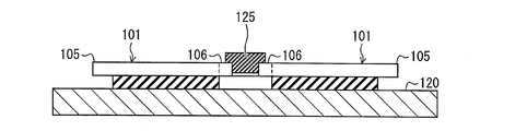
- Patent Document 1 when annealing is performed on a disk substrate 101 of a molded body, an outer peripheral end portion 105 of one main surface of the disk substrate 101 is avoided in order to avoid burrs of the disk substrate 101.
- a configuration is disclosed in which the disk substrate 101 is supported using a substrate support member 120 that supports the entire surface excluding the inner peripheral end 106.
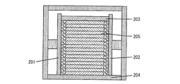
- Patent Document 2 in order to prevent warping of the molded body 205 during annealing of the molded body 205 of the plate-like thermoplastic resin, the front and back directions of the molded body 205 and a pair of both side surface directions are disclosed.
- a configuration in which fixing plates 201 to 204 such as aluminum are installed from a total of four directions is disclosed.
- Patent Document 3 in the annealing apparatus for a wafer-shaped molded body, a heating unit having a heating plate and a cooling unit having a cooling plate are individually provided, and by enabling continuous processing of heating and cooling of the molded body, A configuration for removing distortion of a molded product is disclosed.
- Japanese Patent Publication Japanese Patent Laid-Open No. 2001-38816 (published on February 13, 2001)” Japanese Patent Publication “Japanese Patent Laid-Open No. 2005-47126 (published on Feb. 24, 2005)” Japanese Patent Publication “Japanese Patent Laid-Open No. 11-123770 (published May 11, 1999)”
- Patent Document 3 the molded body is rapidly cooled during conveyance to the cooling unit and in the cooling unit, and there is a risk of warping due to uneven cooling.
- the present invention has been made to solve the above-described problems, and an object thereof is to realize an annealing method, an annealing jig, and an annealing apparatus capable of obtaining a molded body free from residual stress and distortion. is there.
- an annealing method for annealing a molded body molded from a molding material in a molding step, and heating the molded body, It has the 1st process of releasing the stress of a molded object, and the 2nd process of correcting the curvature of the said molded object by heating, applying a load to the said molded object, It is characterized by the above-mentioned.
- An annealing jig is used to apply a load to a molded body that is molded from a molding material and is reheated after being heated to relieve stress. It is characterized by comprising a set of two annealing jigs sandwiching the upper and lower surfaces of the molded body.
- the annealing method according to one aspect of the present invention is an annealing method for annealing a molded body molded from a molding material in a molding process, and the stress of the molded body is obtained by heating the molded body. And a second step of correcting warping of the molded body by heating while applying a load to the molded body, so that the stress is sufficiently released, and residual stress and strain are reduced. There exists an effect that a molded object without can be obtained.
- FIG. 6 is a cross-sectional view illustrating a state in which the molded body illustrated in FIG. 4 is sandwiched by the annealing jig illustrated in FIG. 5. It is a figure for demonstrating a lens position error.
- FIG. 1 is a top view which shows the lens position error of the molded object obtained by the annealing method which concerns on the Example of this invention
- (b) is the lens position error of the molded object obtained by the conventional annealing method.
- FIG. It is a figure for demonstrating the relationship between the temperature difference of the upper and lower surfaces of a molded object, and the curvature of a molded object. It is a figure which shows the equivalent thermal circuit at the time of cooling with an air convection oven. It is sectional drawing which shows the annealing apparatus which concerns on Example 2 of this invention, and has shown the state before throwing a molded object.
- the annealing process of the molded body performed after the molded body is molded from the molding material is divided into two processes, a stress release process (first process) and a warp correction process (second process).
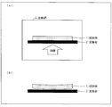
- FIG. 1 is a schematic diagram for explaining the stress release process.
- the molded object 1 is mounted in the support stand 2, and the stress of the molded object 1 is released by heating in the heating furnace (oven) 3.
- the heating furnace oxygen
- the molded body 1 may be placed on the floor surface of the heating furnace 3. At this time, the molded body 1 is not fixed in order not to inhibit the movement of the molding material molecules accompanying the stress release. Therefore, as shown in FIG. 1B, the molded body 1 taken out from the heating furnace 3 is warped.
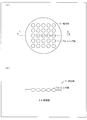
- FIG. 2 is a schematic diagram for explaining a warp correction process.
- FIG. 2 (a) in order to correct the warp remaining in the molded body 1, both surfaces of the molded body 1 are sandwiched between two annealing jigs 4 and the molded body 1 is heated. Thereby, the molded object 1 softens at high temperature, and the curvature of the molded object 1 is corrected by the load of the annealing jig 4 as shown in FIG.
- Patent Document 2 has a problem in that the stress is not sufficiently released because the movement of the material molecules of the molded body is restricted.
- the movement of the material molecules of the molded body 1 is mostly completed in the stress release process.
- the warp correction process in which the molded body 1 is fixed by the annealing jig 4, the amount of movement of the material molecules is small. For this reason, in the warp correction step, the stress is sufficiently released, and the molded body 1 free from distortion and warpage can be obtained.
- a heat insulating member 5 is inserted between the lower annealing jig 4 and the support base 2, and between the lower annealing jig 4 and the surface of the support base 2. It is preferable to form an air flow path.
- the lower annealing jig 4 is placed on the floor surface of the heating furnace 3, it is preferable to form an air flow path between the lower annealing jig 4 and the floor surface of the heating furnace 3. .
- the molded object 1 can be cooled by air convection in addition to radiation and conduction.
- the heat capacity of the upper annealing jig 4 and the heat capacity of the lower annealing jig 4 coincide, and the thermal resistance of the upper annealing jig 4 and the thermal resistance of the lower annealing jig 4 are the same. The difference can be reduced.
- FIG. 4A is a plan view of the molded body 11 according to the present embodiment
- FIG. 4B is a cross-sectional view of the molded body 11 along AA ′.
- the molded body 11 is a disk-shaped wafer level lens, and uses a silicone thermosetting resin having a glass transition point Tg after curing of about 140 ° C. and a molding temperature of 150 ° C. as a molding material.
- the size of the molded body 11 is a diameter ⁇ : 100 mm and a thickness: 0.74 mm.
- a plurality of lens portions (projecting element portions) 11 a are regularly formed on both surfaces of the molded body 11.
- FIG. 5A is a plan view of the annealing jig 14 according to this embodiment
- FIG. 5B is a cross-sectional view of the annealing jig 14 taken along the line B-B ′.
- the annealing jig 14 is a square aluminum flat plate having a side length of 100 mm and a thickness of 10 mm.
- the mass of the annealing jig 14 is 270 g.
- the annealing jig 14 is composed of a set of two sheets, and the molded body 11 is sandwiched between the two annealing jigs 14 in the warp correction process.
- a digging 14 a having a depth of 3 mm is formed at a position corresponding to the lens portion 11 a of the molded body 11.
- 5 ⁇ 25 ⁇ 25 digs 14a are arranged at a pitch of 3.44 mm.
- an air convection oven is used as an annealing apparatus.
- the stress release step is intended to complete the curing reaction of the molded body 11 (stabilize the refractive index of the molding material) and release the residual stress accompanying the molding.
- Target temperature 180 ° C.
- heating time The molded body 11 is heated in 30 minutes. Specifically, the following steps (1) to (3) are performed.
- the stress is released in a short time by heating the molded body 11 at a temperature higher than the glass transition point (140 ° C.).
- the heating temperature is lower than the glass transition point, the time required for stress release becomes very long (on the order of several hours or several days).
- the heating temperature is too high, the shape of the molded body may be collapsed. If the heating time is too long, the shape of the molded body may be collapsed, or deterioration such as yellowing may occur. If the heating time is too short, the refractive index may not be stable.
- the warp correction process aims to correct the warp of the molded body 11 generated in the stress release process.
- the molded body 11 is heated again at a target temperature of 180 ° C. and a heating time of 60 minutes. Specifically, the following steps (4) to (10) are performed.
- E Young's modulus of molding material at annealing temperature
- h Thickness of molded body
- the mass of the annealing jig 14 according to the present embodiment is 270 g, a sufficient load can be applied.
- the lens position error which is the distance from the ideal lattice point corresponding to the single lens position, and the lens position variation of the single lens position (the coordinates of each lens unit) are obtained. It was.
- the ideal lattice point means a lattice point of an orthogonal lattice (ideal lattice) in which the pitch, shift amount, and rotation amount are determined so that the sum of squares of the lens position error is minimized.
- the lens position variation is a mean square of the lens position error.
- the lens position error and the lens position variation were also measured for the molded body obtained by the conventional annealing method.
- 10 molded bodies were annealed by the annealing method according to this example and the conventional annealing method, respectively.
- FIG. 8A is a plan view showing a lens position error of the sample A which is a molded body obtained by the annealing method according to the present embodiment
- FIG. 8B is obtained by the conventional annealing method. It is a top view which shows the lens position error of the sample B which is the obtained molded object. The lens position error is enlarged and displayed 200 times the distance between the lattice points.
- Table 1 shows the average shrinkage rate and position variation of Sample A and Sample B.
- the average shrinkage rate means the shrinkage rate of the ideal lattice pitch with respect to the dug pitch (3.44 mm) of the annealing jig.
- the warpage of the molded body 11 can be suppressed, and therefore there is no direct restriction on the temperature drop rate.
- the thermal resistance between the air and the annealing jig is different between the upper surface side and the lower surface side of the molded body, it is desirable to provide a restriction on the temperature drop rate.
- warpage occurs due to the difference in thermal expansion between the upper and lower surfaces of the molded body.
- the warping is leveled by the annealing jig.
- the internal stress is accumulated correspondingly, so that the warping occurs later.
- Temperature T L -temperature T U of lower surface side annealing jig) is estimated.
- the molding is performed.
- Body thermal resistance R W 0.32 K / W
- thermal resistance R I 0.57 K / W between upper surface side annealing jig and lower surface side annealing jig, temperature difference ⁇ T I ⁇ 0. 36K.
- the average heat transfer coefficients of the upper surface side annealing jig and the lower surface side annealing jig are respectively 20 W / K ⁇ m 2 and 15 W / K ⁇ m 2 ( ⁇ measured value in air convection oven ⁇ wind speed 2 m / s) Calculated value), the thermal resistance R U between the upper surface side annealing jig and the atmosphere is 3.6 K / W, and the thermal resistance R L between the lower surface side annealing jig and the atmosphere is 4.8 K / W. . Therefore, a ⁇ 1.2 K / min may be set.
- the temperature difference between the annealing jig on the upper surface side and the annealing jig on the lower surface side is 0.3K or less and the average temperature cooling rate is 1K / min or less.
- the temperature difference between the atmosphere and the compact is 10 to 30 K. Therefore, while the atmosphere temperature in the air convection oven is within the range of glass point transfer Tg + 10 to Tg-50K after the stress release process of the molding material, the upper surface side annealing jig and the lower surface side annealing jig It is desirable to set the temperature difference of 0.3K or less and the average temperature drop rate of the ambient temperature to 1K / min or less.
- Thermal resistance R L between the lower surface annealing fixture and the atmosphere is greater than the thermal resistance R U between the upper surface annealing jig and atmosphere, the lower surface annealing jig thinner than the upper surface annealing jig formed
- the heat capacity C L of the lower surface side annealing jig can be reduced, and C L R L -C U R U can be brought close to zero.
- the heat transfer coefficient of the lower-side annealing jig is the upper-side annealing. This is about 3/4 of the jig (R L ⁇ 4R U / 3). Therefore, the thickness of the lower surface side annealing jig may be about 3 ⁇ 4 of that of the upper surface side annealing jig.
- the optimum thickness of the annealing jig varies depending on the ratio of the thermal emissivity of the upper surface side annealing jig and the lower surface side annealing jig. Therefore, for example, by setting the thickness of the lower surface side annealing jig to 1/2 to 1 times, more preferably 5/8 to 7/8 times the thickness of the upper surface side annealing jig, the temperature difference [Delta] T I can be easily reduced.
- R U and R L can be lowered by applying a treatment for improving the thermal emissivity to the annealing jig.
- a treatment for improving the thermal emissivity of the annealing jig ⁇ Black body coating ⁇ Black body tape application ⁇ Black alumite treatment ⁇ Annealing jig is covered with an insulator with high thermal emissivity.
- the average convection heat transfer coefficient of each surface of the upper surface side annealing jig and the lower surface side annealing jig is 20 W / K ⁇ m 2 and 15 W / K ⁇ m 2 , and the radiant heat transfer coefficient is 0 W / K ⁇ m 2 to 9 W. If it is improved to / K ⁇ m 2 , ⁇ T I is reduced to approximately 2/3. Thereby, curvature can be reduced to 2/3, or the upper limit of the temperature drop rate can be expanded 1.5 times.
- the molded body 11 to be annealed is the same as the molded body 11 according to the first embodiment except that it is an epoxy thermosetting resin and has a thickness of 0.5 mm.
- the contents of the process are also the same as in the first embodiment.
- FIG. 11 is a cross-sectional view showing the annealing apparatus 10 according to the present embodiment.
- the annealing apparatus 10 has an internal space surrounded by a heat insulating wall, and two annealing jigs 14 and two heating / cooling devices (temperature control plates, temperature control members) 15 are provided in the internal space. Yes.
- the heating / cooling machine 15 may not be plate-shaped.
- the heating / cooling machine 15 has a heating wire and a cooling water tank in an aluminum base material.
- the other surface of the annealing jig 14 where the digging 14 a is not formed is attached to the heating / cooling machine 15.
- One heating / cooling machine 15 is placed on the inner bottom surface of the annealing apparatus 10, and the other heating / cooling machine 15 is supported by a support rod 16. Thereby, the surface in which the dug 14a of the two annealing jigs 14 is formed is opposed to each other.
- the support rod 16 can be moved downward (press direction) by a servo motor 17. Thereby, the annealing jig 14 on the upper surface side is movable relative to the annealing jig 14 on the lower surface side.
- a load cell 18 is provided at a connection point between the annealing jig 14 on the upper surface side and the support rod 16.
- the load cell 18 detects a press load on the molded body 11 and feeds back the detection result to the servo motor 17.
- the position where the load cell 18 is provided is not particularly limited as long as the load can be detected, such as the lower side of the annealing jig 14 on the lower surface side.
- a heat insulating plate may be interposed between the heating / cooling device 15 and the load cell 18.
- the stress release process in this embodiment is the same as that in the first embodiment.
- the molded body 11 whose stress is released is heated again at a target temperature of 180 ° C. and a heating time of 5 minutes. That is, the warp correction process according to the present embodiment is different from the warp correction process according to the first embodiment.
- the heating time and the cooling time are different from those in the first embodiment. Note that the relationship between the temperature difference between the upper and lower surfaces of the molded body and the warpage of the molded body described with reference to FIG.
- the annealing method according to one aspect of the present invention is an annealing method for annealing a molded body molded from a molding material in a molding process, and the stress of the molded body is obtained by heating the molded body. And a second step of correcting warpage of the molded body by heating while applying a load to the molded body.
- the molded body in the first step, by heating the molded body without fixing, the stress of the molded body is released and the molded body is warped. Therefore, in the second step, the molded body is heated while applying a load. Thereby, a molded object softens at high temperature, and the curvature of a molded object is corrected with a load.
- the material molecules of the molded body since the movement of the material molecules of the molded body is mostly completed in the first step, in the second step, the material molecules can be heated with very little movement. For this reason, in a 2nd process, stress is fully released and the molded object without a residual stress and distortion can be obtained.
- the temperature of the molded body is 20 K lower than the glass transition point after the first step of the molding material from the glass transition point. While the temperature is higher than 20K, the temperature difference between the upper surface of the molded body and the lower surface of the molded body is preferably suppressed to 0.2K or less.
- the load is P
- the maximum warpage amount of the molded body is ⁇
- the Young's modulus at the annealing temperature of the molding material of the molded body is E
- the thickness of the molded body is h
- the gravitational acceleration is g
- a load sufficient for warping correction can be applied to the molded body.
- the molded body in the first step, is preferably heated to a temperature higher than the maximum temperature in the molding step.
- the curing reaction of the unreacted portion of the molded body after the molding process can be completed.
- the molded body in the first step, is preferably heated to a temperature higher than a glass transition point after molding of the molding material.
- the molded body in the second step, is preferably heated to a temperature higher than the glass transition point after the first step of the molding material.
- the residual stress of the molded body after the molding process can be released in a short time.
- the second step includes a loading step of applying a load to the molded body by sandwiching the upper and lower surfaces of the molded body with a set of two annealing jigs, It is preferable to have a heating step of heating the molded body subjected to the heating by an air convection oven and a cooling step of cooling the heated molded body.
- the atmospheric temperature in the air convection oven is lower than the glass transition point from a temperature that is 50K lower than the glass transition point after the first step of the molding material. While the temperature is in the range of 10K higher, it is preferable to suppress the temperature difference between the annealing jig on the upper surface side of the molded body and the annealing jig on the lower surface side of the molded body to 0.3K or less.
- the atmospheric temperature in the air convection oven is lower than the glass transition point from a temperature that is 50K lower than the glass transition point after the first step of the molding material. While the temperature is in the range of 10K higher, it is preferable that the average temperature decreasing rate of the ambient temperature is 1K / min or less.
- the warpage of the molded body can be made extremely small.
- an air flow path is formed between the annealing jig on the lower surface side of the molded body and the surface supporting the annealing jig on the lower surface side. Is preferred.
- the molded body can be cooled by air convection in addition to radiation and conduction. For this reason, the heat capacity of the annealing jig on the upper surface side and the heat capacity of the annealing jig on the lower surface side coincide with each other, and the difference between the thermal resistance of the annealing jig on the upper surface side and the thermal resistance of the annealing jig on the lower surface side is reduced. be able to.
- the process time can be shortened.
- An annealing jig is used to apply a load to a molded body that is molded from a molding material and is reheated after being heated to relieve stress. It is characterized by comprising a set of two annealing jigs sandwiching the upper and lower surfaces of the molded body.
- a load can be applied to the molded body by sandwiching the upper and lower surfaces of the molded body between the two annealing jigs. By heating the molded body in this state, the warpage of the molded body can be corrected.
- the annealing jig on the lower surface side of the molded body is thinner than the annealing jig on the upper surface side of the molded body.
- the thickness of the annealing jig on the lower surface side is preferably 1/2 to 1 times the thickness of the annealing jig on the upper surface side.
- the thickness of the annealing jig on the lower surface side is preferably 5/8 to 7/8 times the thickness of the annealing jig on the upper surface side.
- the annealing jig is subjected to a treatment for improving thermal emissivity.
- the surface of the annealing jig is a heat radiation surface, the temperature difference between the two annealing jigs can be easily reduced.
- the mass of the annealing jig on the upper surface side of the molded body is m
- the maximum warpage amount of the molded body is ⁇
- the Young's modulus at the annealing temperature of the molding material of the molded body Is E
- the thickness of the molded body is h
- the diameter of the molded body the length of one side or the length in the short direction is L
- the gravitational acceleration is g.
- a load sufficient for warping correction can be applied to the molded body.
- a digging is formed on the contact surface with the molded body.
- a through hole is formed on a contact surface with the molded body.
- a plurality of the digs are regularly formed.
- a plurality of the through holes are regularly formed.
- An annealing apparatus includes any one of the annealing jigs described above and a temperature control member that controls the temperature of the annealing jig.
- the process time can be shortened.
- the temperature control member is configured to cause the annealing jig on the upper surface side of the molded body and the annealing treatment on the lower surface side of the molded body to cool the annealing jig. It is preferable to suppress the temperature difference from the tool to 0.3K or less.
- the maximum load that the temperature control member can apply to the molded body is P
- the maximum warpage amount of the molded body is ⁇
- the Young's modulus at the annealing temperature of the molding material of the molded body is E, where the thickness of the molded body is h, the diameter of the molded body, the length of one side or the length in the lateral direction is L, and the gravitational acceleration is g.
- a load sufficient for warping correction can be applied to the molded body.
- the present invention is suitable for annealing a molded body molded from a molding material.
Landscapes
- Physics & Mathematics (AREA)
- Thermal Sciences (AREA)
- Chemical & Material Sciences (AREA)
- Crystallography & Structural Chemistry (AREA)
- Processing And Handling Of Plastics And Other Materials For Molding In General (AREA)
- Re-Forming, After-Treatment, Cutting And Transporting Of Glass Products (AREA)
- Injection Moulding Of Plastics Or The Like (AREA)
Abstract
Description
本発明では、成形材料から成形体を成形した後に行なわれる成形体のアニール工程を応力解放工程(第1の工程)および反り矯正工程(第2の工程)の2工程に分割して行う。
以下、第1の実施例について、図4~図6を参照して説明する。
図4の(a)は、本実施例に係る成形体11の平面図であり、図4の(b)は、成形体11のA-A’断面図である。成形体11は、円盤状のウェハレベルレンズであり、硬化後のガラス転移点Tg:約140℃、成形温度:150℃のシリコーン系熱硬化樹脂を成形材料としている。成形体11のサイズは、直径φ:100mm、厚み:0.74mmである。図4の(b)に示すように、成形体11の両面には、レンズ部(突出素子部)11aが規則的に複数形成されている。
以上の構成において、本実施例に係る応力解放工程について説明する。応力解放工程は、成形体11の硬化反応を完結(成形材料の屈折率を安定)させること、および、成形に伴う残留応力を解放することを目的としており、目標温度:180℃、加熱時間:30分で成形体11を加熱する。具体的には、以下の(1)~(3)の工程を行う。
成形材料から成形された成形体11の靭性がある程度残存している間に、成形体11の周囲のバリを切り取っておく。まず、バリをハサミで切り取る、このとき、成形体11を形成するウェハ内部に割れが入らないよう注意する。続いて、成形体11に除電ブローを当てて帯電を除去した後、ブロアで吹いてゴミを飛ばす。残ったゴミは、ピンセット等で除去する。その後、成形体11の表裏面とも、目視できるゴミが無いことを確認する。
アニール装置の温度表示が180℃になっていることを確認後、アルミホイル上に成形体11を平置きにして、アニール装置に投入する。投入の際にアニール装置の庫内温度が下がるので、目標温度-10K(170℃)まで復帰してから加熱時間をカウントする。なお、成形体11同士を重ねると融着する恐れがある。
アニール装置の庫内温度が170℃以上になってから30分後に、アルミホイルごと成形体11を取り出す。この加熱時間は、成形体11の昇温時定数の実測値200秒より十分大きく、成形体11の温度はほぼ目標温度に到達している。取り出し後、成形体11を自然空冷する。
続いて、本実施例に係る反り矯正工程について説明する。反り矯正工程は、応力解放工程で生じた成形体11の反りを矯正することを目的とする。目標温度:180℃、加熱時間:60分で成形体11を再度加熱する。具体的には、以下の(4)~(10)の工程を行う。
成形体11をアニール治具14で完全に平坦に押さえられるように、成形体11に付着したゴミを除去する。まず、成形体11に除電ブローを当てて帯電を除去した後、ブロアで吹いてゴミを飛ばす。残ったゴミは、ピンセット等で除去する。その後、成形体11の表裏面とも、目視できるゴミが無いことを確認する。
アニール治具14の成形体11と当接する面に汚れが付着している場合、イソプロピルアルコールを染み込ませたベンコットで拭き取る。続いて、ブロアで吹いてゴミを飛ばす。
成形体11のレンズ部11aが平面部より突出している場合、レンズ部11aをアニール治具14に当てないように注意しながら、図6に示すように、成形体11をアニール治具14に挟み込む。その状態で、2箇所をカプトンテープで固定する。なお、熱膨張等で成形体11が厚くなる場合があるので、カプトンテープは僅かにたわませて貼りつける。また、カプトンテープの張力で成形体11に荷重をかけるのでなく、アニール治具14の重さで成形体11に荷重をかける。

h:成形体の厚み
R:成形体の半径
成形体11について、δ=10mm、E=200MPa、h=1mm、R=50mmとすると、P=1.6Nとなる。これに対し、本実施例に係るアニール治具14の質量は270gであるため、十分な荷重をかけることができる。
アニール装置の温度表示が180℃になっていることを確認後、アニール治具14と成形体11との位置関係がずれないよう注意しながら、アニール治具14と成形体11とからなる治具セットをアニール装置に投入する。このとき、アニール装置の庫内の棚板に対し、コルク等の断熱部材で治具セットを浮かせて置いても良い。投入の際に庫内温度が下がるので、目標温度-10K(170℃)まで復帰してから加熱時間をカウントする。
庫内温度が170℃以上になってから60分後に、加熱を止める。この加熱時間は、アニール治具14の昇温時定数の実測値900秒の4倍であり、成形体11の温度は177℃に到達していると見積もられる。続いて、冷却中の成形体11の上下面の温度差により生じる反りを抑えるため、徐冷する。庫内温度がガラス点移転Tg+10~Tg-50K(150~90℃)の範囲で冷却レートを1K/分以下とすることにより、反りが10μm程度のオーダーとなる。
アニール装置の庫内温度が、Tg-50K(90℃)になってから5分以上経過後、治具セットを取り出し、自然空冷する。
5分以上自然空冷した後、治具セットを開いて成形体を回収する。
検証実験では、上記の応力解放工程および反り矯正工程を経て、成形体を回収後、各レンズ部の成形体面内の位置(XY)座標を、Nikon社製の画像測定システムNexiv(登録商標)によって測定した。
測定結果を図8に示す。図8の(a)は、本実施例に係るアニール方法によって得られた成形体であるサンプルAのレンズ位置誤差を示す平面図であり、図8の(b)は、従来のアニール方法によって得られた成形体であるサンプルBのレンズ位置誤差を示す平面図である。なお、レンズ位置誤差は、格子点間の距離に対し200倍に拡大表示している。
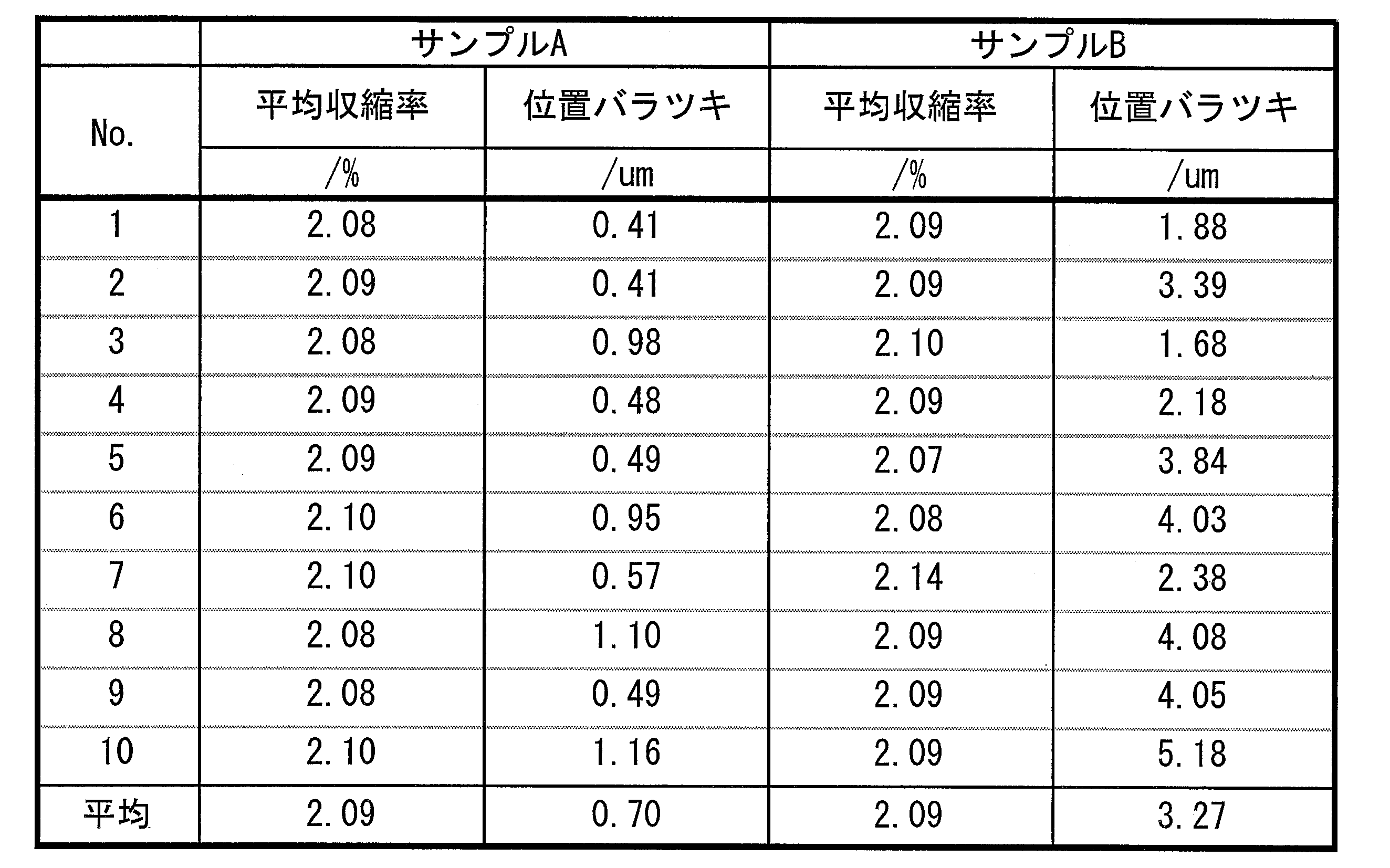
図9に示すように、成形体の上下面でΔTWの温度差があるとき、熱膨張差により、以下の関係が成り立つ。

α: 成形材料の熱膨張係数
ΔTW: 成形体の上下面の温度差
r: 成形体に生じる反りの曲率半径
ここで、成形体のサイズ(成形体が円形の場合、直径)をXとすると、成形体の反り量ΔZは、以下の式により求まる。

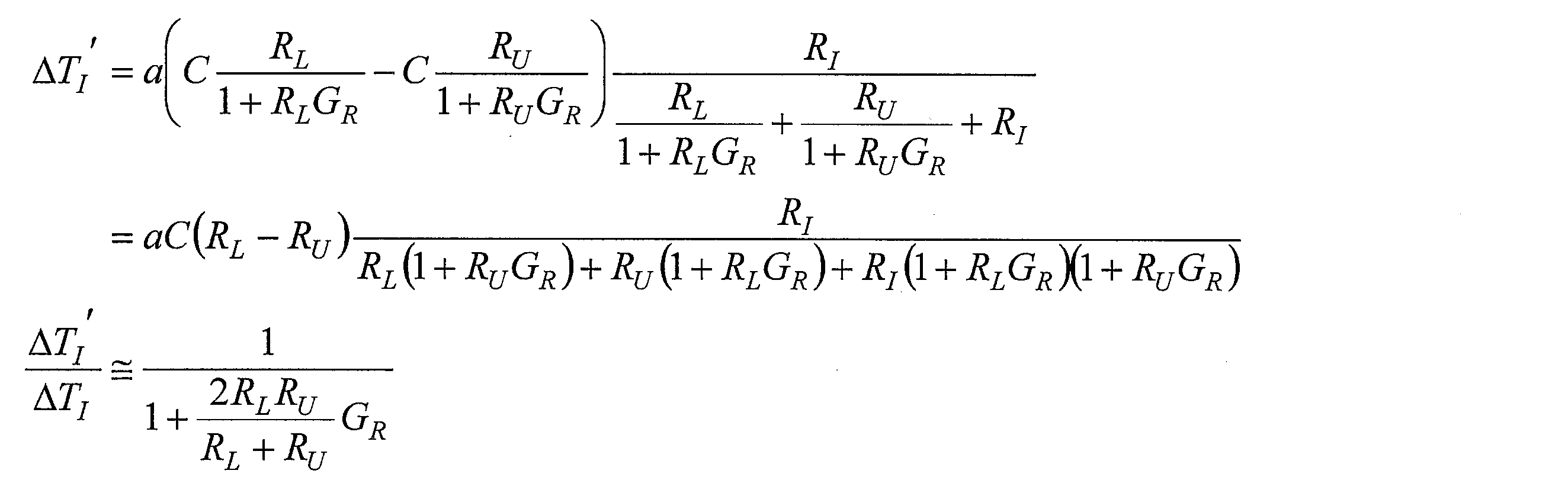
雰囲気温度が降温レートaで冷却され、上面側アニール治具および下面側アニール治具も共に同じ降温レートで冷却されている場合の、上下アニール治具の温度差ΔTI(=上面側アニール治具の温度TL-下面側アニール治具の温度TU)を見積もる。アニール治具内部の熱抵抗、および成形体の熱容量を無視して、オーブンでの冷却時の等価熱回路を、図10に示すように近似する。上面側アニール治具と雰囲気の間の熱抵抗・熱流をRU・qU、上面側アニール治具と下面側アニール治具の間の熱抵抗・熱流をRI・qI、下面側アニール治具と雰囲気の間の熱抵抗・熱流をRL・qLとすると、温度差と熱流の関係から、
TU-TA=qURU
TL-TA=qLRL
TL-TU=qIRI
となる。また、上面側アニール治具の熱容量をCU、下面側アニール治具の熱容量をCLとすると、降温レートと熱流の関係から、
qU-qI=aCU
qL+qI=aCL
これらの式から、qU、qI、qLおよびTAを消去してΔTIを求めると、

RI=2RC+RW
であるため、成形体の上下面の温度差ΔTWは、

望ましい温度差ΔTWおよび降温レートaの範囲を、厳しめの条件で見積もると、以下のようになる。成形体の厚みd=0.5mm、成形材料の熱膨張係数α=1×10⁻⁴/K、成形体のサイズX=100mm、成形体の反り量ΔZ<50μmのとき、
ΔTW<0.2K
となる。
なお、上下のアニール治具の温度差を低減する方法として、下面側アニール治具を上面側アニール治具よりも薄く形成する方法、および、アニール治具を黒塗りする方法がある。
・黒体塗装
・黒体テープの貼付
・ブラックアルマイト処理
・熱放射率の高い絶縁体でアニール治具を覆う
といった処理が挙げられる。

以下、第2の実施例について、図11および図12を参照して説明する。本実施例では、アニールされる成形体11は、エポキシ系熱硬化樹脂である点、および、厚みが0.5mmである点以外は、実施例1に係る成形体11と同一であり、応力解放工程の内容も、実施例1と同一である。
図11は、本実施例に係るアニール装置10を示す断面図である。アニール装置10は、断熱壁で囲まれた内部空間を有しており、当該内部空間に、アニール治具14および加熱冷却機(温度制御板、温度制御部材)15がそれぞれ2つずつ設けられている。加熱冷却機15は、板状でなくてもよい。
前述のように、本実施例における応力解放工程は、実施例1と同様である。本実施例に係る反り矯正工程では、目標温度:180℃、加熱時間:5分で、応力が解放された成形体11を再度加熱する。すなわち、本実施例に係る反り矯正工程は、加熱時間が実施例1における反り矯正工程と異なる。
成形体11のレンズ部11aが平面部より突出している場合、レンズ部11aをアニール治具14に当てないように注意しながら、図12に示すように、成形体11をアニール治具14に挟み込む。
続いて、成形体11への荷重値を、実施例1において説明した式(A)により求められる荷重P以上に設定する。荷重値が設定値で一定となるよう、ロードセル18の検出値をサーボモータ17にフィードバックする。
続いて、加熱冷却機15の温度を以下のように制御する。
待機温度:80℃
加熱(加熱工程):20K/分→180℃、5分保持
冷却(冷却工程):5K/分→80℃
すなわち、5分かけて180℃に加熱し、5分経過後、20分かけて80℃に冷却する。
冷却を完了して5分以上経過後、治具セットを取り出し、自然空冷する。
本発明は上述した各実施例に限定されるものではなく、請求項に示した範囲で種々の変更が可能であり、異なる実施例にそれぞれ開示された技術的手段を適宜組み合わせて得られる形態についても本発明の技術的範囲に含まれる。
〔まとめ〕
以上のように、本発明の一態様に係るアニール方法は、成形工程において成形材料から成形された成形体をアニールするアニール方法であって、前記成形体を加熱することにより、前記成形体の応力を解放する第1の工程と、前記成形体に荷重をかけながら加熱することにより、前記成形体の反りを矯正する第2の工程とを有することを特徴としている。



2 支持台
3 加熱炉
4 アニール治具
5 断熱部材
10 アニール装置
11 成形体
11a レンズ部
14 アニール治具
15 加熱冷却機(温度制御部材)
16 支持ロッド
17 サーボモータ
18 ロードセル
Claims (24)
- 成形工程において成形材料から成形された成形体をアニールするアニール方法であって、
前記成形体を加熱することにより、前記成形体の応力を解放する第1の工程と、
前記成形体に荷重をかけながら加熱することにより、前記成形体の反りを矯正する第2の工程とを有すること
を特徴とするアニール方法。 - 請求項1に記載のアニール方法であって、
前記第2の工程において、
前記成形体の温度が、前記成形材料の前記第1の工程の後におけるガラス転移点よりも20K低い温度から当該ガラス転移点よりも20K高い温度である間、
前記成形体の上面と前記成形体の下面との温度差を0.2K以下に抑制すること
を特徴とするアニール方法。 - 請求項1または2に記載のアニール方法であって、
前記荷重をP、前記成形体の最大反り量をδ、前記成形体の成形材料のアニール温度におけるヤング率をE、前記成形体の厚みをh、前記成形体の直径、一辺の長さ又は短手方向の長さをL、重力加速度をgとすると、

を特徴とするアニール方法。 - 請求項1~3のいずれか1項に記載のアニール方法であって、
前記第1の工程において、
前記成形体を、前記成形工程における最高温度よりも高い温度に加熱すること
を特徴とするアニール方法。 - 請求項1~3のいずれか1項に記載のアニール方法であって、
前記第1の工程において、
前記成形体を、前記成形材料の成形後におけるガラス転移点よりも高い温度に加熱すること
を特徴とするアニール方法。 - 請求項1~5のいずれか1項に記載のアニール方法であって、
前記第2の工程において、
前記成形体を、前記成形材料の前記第1の工程の後におけるガラス転移点よりも高い温度に加熱すること
を特徴とするアニール方法。 - 請求項1~6のいずれか1項に記載のアニール方法であって、
前記第2の工程は、
前記成形体の上下面を2枚1組のアニール治具で挟むことにより、前記成形体に荷重をかける荷重工程と、
荷重をかけられた前記成形体を空気対流オーブンにより加熱する加熱工程と、
加熱された前記成形体を冷却する冷却工程とを有すること
を特徴とするアニール方法。 - 請求項7に記載のアニール方法であって、
前記冷却工程において、
前記空気対流オーブン内の雰囲気温度が、前記成形材料の前記第1の工程の後におけるガラス転移点より50K低い温度からガラス転移点より10K高い温度の範囲内である間、
前記成形体の上面側の前記アニール治具と前記成形体の下面側の前記アニール治具との温度差を0.3K以下に抑制すること
を特徴とするアニール方法。 - 請求項7または8に記載のアニール方法であって、
前記冷却工程において、
前記空気対流オーブン内の雰囲気温度が、前記成形材料の前記第1の工程の後におけるガラス転移点より50K低い温度からガラス転移点より10K高い温度の範囲内である間、
前記雰囲気温度の平均降温レートを1K/分以下とすること
を特徴とするアニール方法。 - 請求項7~9のいずれか1項に記載のアニール方法であって、
前記成形体の下面側の前記アニール治具と当該下面側の前記アニール治具を支持する面との間に、空気の流路が形成されていること
を特徴とするアニール方法。 - 請求項1~6のいずれか1項に記載のアニール方法であって、
前記成形体の上下面を温度制御部材によって温度制御可能な2枚1組のアニール治具で挟むことにより、前記成形体に荷重をかける荷重工程と、
荷重をかけられた前記成形体を前記温度制御部材によって加熱する加熱工程と、
加熱された前記成形体を前記温度制御部材によって冷却する冷却工程とを有すること
を特徴とするアニール方法。 - 成形材料から成形され、加熱されることにより応力が解放された平板状の成形体を再度加熱する際に、前記成形体に荷重をかけるために用いられるアニール治具であって、
前記成形体の上下面を挟む2枚1組のアニール治具で構成されること
を特徴とするアニール治具。 - 請求項12に記載のアニール治具であって、
前記成形体の下面側の前記アニール治具が前記成形体の上面側の前記アニール治具よりも薄いこと
を特徴とするアニール治具。 - 請求項13に記載のアニール治具であって、
前記下面側の前記アニール治具の厚みは、前記上面側の前記アニール治具の厚みの1/2~1倍であることを特徴とするアニール治具。 - 請求項13に記載のアニール治具であって、
前記下面側の前記アニール治具の厚みは、前記上面側の前記アニール治具の厚みの5/8~7/8倍であることを特徴とするアニール治具。 - 請求項12~15のいずれか1項に記載のアニール治具であって、
前記アニール治具に、熱放射率を向上させる処理が施されていること
を特徴とするアニール治具。 - 請求項12~16のいずれか1項に記載のアニール治具であって、
前記成形体の上面側の前記アニール治具の質量をm、前記成形体の最大反り量をδ、前記成形体の成形材料のアニール温度におけるヤング率をE、成形体の厚みをh、成形体の直径、一辺の長さ又は短手方向の長さをL、重力加速度をgとすると、

を特徴とするアニール治具。 - 請求項12~17のいずれか1項に記載のアニール治具であって、
前記成形体との当接面に掘り込みが形成されていること
を特徴とするアニール治具。 - 請求項12~17のいずれか1項に記載のアニール治具であって、
前記成形体との当接面に貫通穴が形成されていること
を特徴とするアニール治具。 - 請求項18に記載のアニール治具であって、
前記掘り込みが規則的に複数形成されていること
を特徴とするアニール治具。 - 請求項19に記載のアニール治具であって、
前記貫通穴が規則的に複数形成されていること
を特徴とするアニール治具。 - 請求項12~21のいずれか1項に記載のアニール治具と、
前記アニール治具の温度を制御する温度制御部材とを有すること
を特徴とするアニール装置。 - 請求項22に記載のアニール装置であって、
前記温度制御部材は、前記アニール治具を冷却している間、前記成形体の上面側の前記アニール治具と前記成形体の下面側の前記アニール治具との温度差を0.3K以下に抑制すること
を特徴とするアニール装置。 - 請求項22または23に記載のアニール装置であって、
前記温度制御部材が前記成形体に印加できる最大荷重をP、前記成形体の最大反り量をδ、前記成形体の成形材料のアニール温度におけるヤング率をE、前記成形体の厚みをh、前記成形体の直径、一辺の長さ又は短手方向の長さをL、重力加速度をgとすると、

を特徴とするアニール装置。
Priority Applications (3)
| Application Number | Priority Date | Filing Date | Title |
|---|---|---|---|
| JP2014531546A JP5972979B2 (ja) | 2012-08-22 | 2013-07-12 | アニール方法、アニール治具およびアニール装置 |
| US14/422,934 US9849639B2 (en) | 2012-08-22 | 2013-07-12 | Annealing method, annealing jig and annealing apparatus |
| CN201380043846.7A CN104582940B (zh) | 2012-08-22 | 2013-07-12 | 退火方法、退火夹具和退火装置 |
Applications Claiming Priority (2)
| Application Number | Priority Date | Filing Date | Title |
|---|---|---|---|
| JP2012183635 | 2012-08-22 | ||
| JP2012-183635 | 2012-08-22 |
Publications (1)
| Publication Number | Publication Date |
|---|---|
| WO2014030462A1 true WO2014030462A1 (ja) | 2014-02-27 |
Family
ID=50149775
Family Applications (1)
| Application Number | Title | Priority Date | Filing Date |
|---|---|---|---|
| PCT/JP2013/069148 Ceased WO2014030462A1 (ja) | 2012-08-22 | 2013-07-12 | アニール方法、アニール治具およびアニール装置 |
Country Status (5)
| Country | Link |
|---|---|
| US (1) | US9849639B2 (ja) |
| JP (1) | JP5972979B2 (ja) |
| CN (1) | CN104582940B (ja) |
| TW (1) | TWI543858B (ja) |
| WO (1) | WO2014030462A1 (ja) |
Cited By (5)
| Publication number | Priority date | Publication date | Assignee | Title |
|---|---|---|---|---|
| JP2017007219A (ja) * | 2015-06-23 | 2017-01-12 | 株式会社ホプニック研究所 | プラスチックレンズの製造方法およびプラスチックレンズの再生方法 |
| JPWO2018008358A1 (ja) * | 2016-07-04 | 2019-04-18 | 日本電気硝子株式会社 | 円盤状ガラス及びその製造方法 |
| JP2021072144A (ja) * | 2019-10-29 | 2021-05-06 | 舒泳軍 | Lpレコード盤の反り修正機 |
| JP2021154366A (ja) * | 2020-03-27 | 2021-10-07 | Jfeスチール株式会社 | H形鋼の製造方法 |
| JP2021154365A (ja) * | 2020-03-27 | 2021-10-07 | Jfeスチール株式会社 | H形鋼の製造方法 |
Families Citing this family (6)
| Publication number | Priority date | Publication date | Assignee | Title |
|---|---|---|---|---|
| CN107053577A (zh) * | 2017-06-05 | 2017-08-18 | 岳西县同兴尼龙橡胶制品有限公司 | 一种精密注塑方法 |
| FR3106296B1 (fr) * | 2020-01-16 | 2022-01-28 | Faurecia Interieur Ind | Procédé de fabrication d’une pièce moulée comprenant une étape de recuit et outil pour la mise en œuvre d’un tel procédé |
| CN111254275B (zh) * | 2020-03-09 | 2021-10-01 | 胡超云 | 一种异型铜带退火用防护设备 |
| MX2022013826A (es) * | 2020-05-08 | 2023-02-09 | Autotech Eng Sl | Sistemas y metodos para la compensacion de deformaciones. |
| CN111958955A (zh) * | 2020-06-30 | 2020-11-20 | 北京航天控制仪器研究所 | 一种尼龙sls制件平面翘曲矫正方法 |
| CN117415242A (zh) * | 2023-11-03 | 2024-01-19 | 智沪铁路设备有限公司 | 一种高速动车组轮装制动盘热矫形修复方法 |
Citations (6)
| Publication number | Priority date | Publication date | Assignee | Title |
|---|---|---|---|---|
| JPS5036581B1 (ja) * | 1970-05-04 | 1975-11-26 | ||
| JPH07188436A (ja) * | 1993-12-25 | 1995-07-25 | Nippo Kk | ポリエステル成形品およびその製造方法 |
| JPH11123770A (ja) * | 1997-10-24 | 1999-05-11 | Dick Seimitsu Buhin Kk | アニーリング装置 |
| JPH11147250A (ja) * | 1997-11-19 | 1999-06-02 | Dainippon Screen Mfg Co Ltd | 樹脂部品の製造方法 |
| JP2005153503A (ja) * | 2003-10-29 | 2005-06-16 | Mitsuboshi Belting Ltd | 板状成形体のソリ矯正方法 |
| JP2008195044A (ja) * | 2007-02-16 | 2008-08-28 | Sekisui Chem Co Ltd | 異型長尺成形体の熱処理方法 |
Family Cites Families (4)
| Publication number | Priority date | Publication date | Assignee | Title |
|---|---|---|---|---|
| US5489404A (en) * | 1994-08-08 | 1996-02-06 | General Electric Company | Process for annealing thermoplastics |
| JP2001038816A (ja) | 1999-08-02 | 2001-02-13 | Sony Corp | 樹脂製ディスク基板の製造方法及び製造用治具 |
| JP4239740B2 (ja) | 2003-07-28 | 2009-03-18 | 凸版印刷株式会社 | 板状熱可塑性樹脂成形体のアニーリング方法 |
| KR20070021452A (ko) * | 2005-08-18 | 2007-02-23 | 삼성전자주식회사 | 보호시트의 어닐링 장치 및 이의 어닐링 방법 |
-
2013
- 2013-07-12 WO PCT/JP2013/069148 patent/WO2014030462A1/ja not_active Ceased
- 2013-07-12 US US14/422,934 patent/US9849639B2/en not_active Expired - Fee Related
- 2013-07-12 CN CN201380043846.7A patent/CN104582940B/zh active Active
- 2013-07-12 JP JP2014531546A patent/JP5972979B2/ja not_active Expired - Fee Related
- 2013-07-30 TW TW102127287A patent/TWI543858B/zh active
Patent Citations (6)
| Publication number | Priority date | Publication date | Assignee | Title |
|---|---|---|---|---|
| JPS5036581B1 (ja) * | 1970-05-04 | 1975-11-26 | ||
| JPH07188436A (ja) * | 1993-12-25 | 1995-07-25 | Nippo Kk | ポリエステル成形品およびその製造方法 |
| JPH11123770A (ja) * | 1997-10-24 | 1999-05-11 | Dick Seimitsu Buhin Kk | アニーリング装置 |
| JPH11147250A (ja) * | 1997-11-19 | 1999-06-02 | Dainippon Screen Mfg Co Ltd | 樹脂部品の製造方法 |
| JP2005153503A (ja) * | 2003-10-29 | 2005-06-16 | Mitsuboshi Belting Ltd | 板状成形体のソリ矯正方法 |
| JP2008195044A (ja) * | 2007-02-16 | 2008-08-28 | Sekisui Chem Co Ltd | 異型長尺成形体の熱処理方法 |
Cited By (7)
| Publication number | Priority date | Publication date | Assignee | Title |
|---|---|---|---|---|
| JP2017007219A (ja) * | 2015-06-23 | 2017-01-12 | 株式会社ホプニック研究所 | プラスチックレンズの製造方法およびプラスチックレンズの再生方法 |
| JPWO2018008358A1 (ja) * | 2016-07-04 | 2019-04-18 | 日本電気硝子株式会社 | 円盤状ガラス及びその製造方法 |
| JP2021072144A (ja) * | 2019-10-29 | 2021-05-06 | 舒泳軍 | Lpレコード盤の反り修正機 |
| JP2021154366A (ja) * | 2020-03-27 | 2021-10-07 | Jfeスチール株式会社 | H形鋼の製造方法 |
| JP2021154365A (ja) * | 2020-03-27 | 2021-10-07 | Jfeスチール株式会社 | H形鋼の製造方法 |
| JP7298529B2 (ja) | 2020-03-27 | 2023-06-27 | Jfeスチール株式会社 | H形鋼の製造方法 |
| JP7500244B2 (ja) | 2020-03-27 | 2024-06-17 | Jfeスチール株式会社 | H形鋼の製造方法 |
Also Published As
| Publication number | Publication date |
|---|---|
| US9849639B2 (en) | 2017-12-26 |
| CN104582940A (zh) | 2015-04-29 |
| JPWO2014030462A1 (ja) | 2016-07-28 |
| US20150224722A1 (en) | 2015-08-13 |
| TWI543858B (zh) | 2016-08-01 |
| JP5972979B2 (ja) | 2016-08-17 |
| CN104582940B (zh) | 2016-08-24 |
| TW201412507A (zh) | 2014-04-01 |
Similar Documents
| Publication | Publication Date | Title |
|---|---|---|
| JP5972979B2 (ja) | アニール方法、アニール治具およびアニール装置 | |
| JP6042945B2 (ja) | ガラス基板を熱処理する装置 | |
| JP2011023438A (ja) | 基板接合体の製造方法 | |
| KR102262440B1 (ko) | 비등온 온도 프로파일을 사용한 유리 물품을 제조하는 방법 | |
| JP6742593B2 (ja) | 支持ガラス基板の製造方法及び積層体の製造方法 | |
| US9576830B2 (en) | Method and apparatus for adjusting wafer warpage | |
| Li et al. | Localized rapid heating process for precision chalcogenide glass molding | |
| CN107592856B (zh) | 玻璃成型设备和方法 | |
| CN103474345A (zh) | 用于对层叠衬底进行成形的方法 | |
| US5827342A (en) | Treatment of glass substrates to compensate for warpage and distortion | |
| TW201636308A (zh) | 玻璃板的彎曲成形裝置及彎曲成形方法 | |
| CN108666230A (zh) | 用于电子产品的整平设备 | |
| JP2016169121A (ja) | 板ガラスの曲げ成形装置及び曲げ成形方法 | |
| JP5375213B2 (ja) | ディスプレイ用のガラス基板の製造方法およびフラットパネルディスプレイの製造方法 | |
| TW202326875A (zh) | 透過誘導曲率之低翹曲固化方法 | |
| KR102509117B1 (ko) | 칩 전사 방법 및 칩 전사 장치 | |
| JP5434977B2 (ja) | ディスプレイ用のガラス基板の製造方法およびフラットパネルディスプレイの製造方法 | |
| JP2009179552A5 (ja) | ||
| KR101769670B1 (ko) | 유리 기판의 제조 방법 및 유리 기판 | |
| JP6598071B2 (ja) | ガラス基板の熱処理方法 | |
| CN105217942B (zh) | 玻璃基板的制造方法及玻璃基板 | |
| US20180370839A1 (en) | Method and system for making articles from preformed materials | |
| JP2017048065A (ja) | ガラス基板の熱処理方法およびガラス基板の製造方法 | |
| JP2005248224A (ja) | 薄膜形成方法、電気光学装置、電子機器 | |
| JP2007169125A (ja) | プレス成型装置、プレス成型方法及びガラス基板の製造方法 |
Legal Events
| Date | Code | Title | Description |
|---|---|---|---|
| 121 | Ep: the epo has been informed by wipo that ep was designated in this application |
Ref document number: 13831447 Country of ref document: EP Kind code of ref document: A1 |
|
| ENP | Entry into the national phase |
Ref document number: 2014531546 Country of ref document: JP Kind code of ref document: A |
|
| WWE | Wipo information: entry into national phase |
Ref document number: 14422934 Country of ref document: US |
|
| NENP | Non-entry into the national phase |
Ref country code: DE |
|
| 122 | Ep: pct application non-entry in european phase |
Ref document number: 13831447 Country of ref document: EP Kind code of ref document: A1 |