WO2014030290A1 - 電子機器、機器操作方法およびプログラム - Google Patents
電子機器、機器操作方法およびプログラム Download PDFInfo
- Publication number
- WO2014030290A1 WO2014030290A1 PCT/JP2013/004395 JP2013004395W WO2014030290A1 WO 2014030290 A1 WO2014030290 A1 WO 2014030290A1 JP 2013004395 W JP2013004395 W JP 2013004395W WO 2014030290 A1 WO2014030290 A1 WO 2014030290A1
- Authority
- WO
- WIPO (PCT)
- Prior art keywords
- knob
- slider
- display
- adjustment
- control unit
- Prior art date
- Legal status (The legal status is an assumption and is not a legal conclusion. Google has not performed a legal analysis and makes no representation as to the accuracy of the status listed.)
- Ceased
Links
Images

Classifications
-
- G—PHYSICS
- G06—COMPUTING OR CALCULATING; COUNTING
- G06F—ELECTRIC DIGITAL DATA PROCESSING
- G06F3/00—Input arrangements for transferring data to be processed into a form capable of being handled by the computer; Output arrangements for transferring data from processing unit to output unit, e.g. interface arrangements
- G06F3/01—Input arrangements or combined input and output arrangements for interaction between user and computer
- G06F3/048—Interaction techniques based on graphical user interfaces [GUI]
- G06F3/0484—Interaction techniques based on graphical user interfaces [GUI] for the control of specific functions or operations, e.g. selecting or manipulating an object, an image or a displayed text element, setting a parameter value or selecting a range
- G06F3/04847—Interaction techniques to control parameter settings, e.g. interaction with sliders or dials
-
- G—PHYSICS
- G06—COMPUTING OR CALCULATING; COUNTING
- G06F—ELECTRIC DIGITAL DATA PROCESSING
- G06F3/00—Input arrangements for transferring data to be processed into a form capable of being handled by the computer; Output arrangements for transferring data from processing unit to output unit, e.g. interface arrangements
- G06F3/01—Input arrangements or combined input and output arrangements for interaction between user and computer
- G06F3/048—Interaction techniques based on graphical user interfaces [GUI]
- G06F3/0487—Interaction techniques based on graphical user interfaces [GUI] using specific features provided by the input device, e.g. functions controlled by the rotation of a mouse with dual sensing arrangements, or of the nature of the input device, e.g. tap gestures based on pressure sensed by a digitiser
- G06F3/0488—Interaction techniques based on graphical user interfaces [GUI] using specific features provided by the input device, e.g. functions controlled by the rotation of a mouse with dual sensing arrangements, or of the nature of the input device, e.g. tap gestures based on pressure sensed by a digitiser using a touch-screen or digitiser, e.g. input of commands through traced gestures
-
- H—ELECTRICITY
- H04—ELECTRIC COMMUNICATION TECHNIQUE
- H04N—PICTORIAL COMMUNICATION, e.g. TELEVISION
- H04N23/00—Cameras or camera modules comprising electronic image sensors; Control thereof
- H04N23/60—Control of cameras or camera modules
- H04N23/62—Control of parameters via user interfaces
-
- H—ELECTRICITY
- H04—ELECTRIC COMMUNICATION TECHNIQUE
- H04N—PICTORIAL COMMUNICATION, e.g. TELEVISION
- H04N23/00—Cameras or camera modules comprising electronic image sensors; Control thereof
- H04N23/60—Control of cameras or camera modules
- H04N23/63—Control of cameras or camera modules by using electronic viewfinders
- H04N23/631—Graphical user interfaces [GUI] specially adapted for controlling image capture or setting capture parameters
-
- H—ELECTRICITY
- H04—ELECTRIC COMMUNICATION TECHNIQUE
- H04N—PICTORIAL COMMUNICATION, e.g. TELEVISION
- H04N23/00—Cameras or camera modules comprising electronic image sensors; Control thereof
- H04N23/60—Control of cameras or camera modules
- H04N23/63—Control of cameras or camera modules by using electronic viewfinders
- H04N23/633—Control of cameras or camera modules by using electronic viewfinders for displaying additional information relating to control or operation of the camera
-
- H—ELECTRICITY
- H04—ELECTRIC COMMUNICATION TECHNIQUE
- H04N—PICTORIAL COMMUNICATION, e.g. TELEVISION
- H04N23/00—Cameras or camera modules comprising electronic image sensors; Control thereof
- H04N23/60—Control of cameras or camera modules
- H04N23/66—Remote control of cameras or camera parts, e.g. by remote control devices
- H04N23/661—Transmitting camera control signals through networks, e.g. control via the Internet
-
- H—ELECTRICITY
- H04—ELECTRIC COMMUNICATION TECHNIQUE
- H04N—PICTORIAL COMMUNICATION, e.g. TELEVISION
- H04N5/00—Details of television systems
- H04N5/222—Studio circuitry; Studio devices; Studio equipment
- H04N5/262—Studio circuits, e.g. for mixing, switching-over, change of character of image, other special effects ; Cameras specially adapted for the electronic generation of special effects
- H04N5/2628—Alteration of picture size, shape, position or orientation, e.g. zooming, rotation, rolling, perspective, translation
-
- G—PHYSICS
- G06—COMPUTING OR CALCULATING; COUNTING
- G06F—ELECTRIC DIGITAL DATA PROCESSING
- G06F2203/00—Indexing scheme relating to G06F3/00 - G06F3/048
- G06F2203/048—Indexing scheme relating to G06F3/048
- G06F2203/04806—Zoom, i.e. interaction techniques or interactors for controlling the zooming operation
-
- H—ELECTRICITY
- H04—ELECTRIC COMMUNICATION TECHNIQUE
- H04N—PICTORIAL COMMUNICATION, e.g. TELEVISION
- H04N23/00—Cameras or camera modules comprising electronic image sensors; Control thereof
- H04N23/60—Control of cameras or camera modules
- H04N23/67—Focus control based on electronic image sensor signals
-
- H—ELECTRICITY
- H04—ELECTRIC COMMUNICATION TECHNIQUE
- H04N—PICTORIAL COMMUNICATION, e.g. TELEVISION
- H04N23/00—Cameras or camera modules comprising electronic image sensors; Control thereof
- H04N23/60—Control of cameras or camera modules
- H04N23/69—Control of means for changing angle of the field of view, e.g. optical zoom objectives or electronic zooming
Definitions
- the present disclosure relates to an electronic device such as a video camera, a device operation method for operating the electronic device, and a program for executing the operation of the electronic device.
- some video cameras are provided with a zoom adjustment lever and a focus adjustment lever, and the zoom adjustment and focus adjustment of a lens are performed by the operation of each lever by a user.
- the zoom adjustment lever and the focus adjustment lever are located at the midpoint when the user is not touching them.
- the zoom lens and the focus lens move to one side at a speed corresponding to the pressing strength.
- the zoom lens and the focus lens move in the reverse direction (the other direction) at a speed corresponding to the pressing strength.
- the user can easily adjust the zoom lens and the focus lens by operating the respective levers.
- Patent Document 1 describes that a zoom lever is provided in a video camera, and variable speed zoom is performed by operating the lever.
- the zoom adjustment lever and the focus adjustment lever described above are operation members of a relatively complicated mechanism that needs to detect the operation amount when the user presses the lever and adjust the driving speed of the adjustment mechanism.
- a button can be used instead of a lever by arranging two buttons, a button for instructing + direction operation and a button for instructing ⁇ direction operation, but in the case of these two buttons, the + direction It is only possible to give an instruction to turn on / off the movement of the lens and to turn on / off the movement in the negative direction, and not to instruct the speed for driving the zoom lens or the focus lens.
- the video camera may be operated from the outside using a remote controller in addition to the case where the user operates with a key or the like arranged on the camera body.
- a remote controller When a remote controller is used, the speed adjustment when driving the zoom lens or the focus lens cannot be performed unless a lever corresponding to the zoom adjustment lever or the focus adjustment lever is arranged on the remote controller.
- An object of the present disclosure is to provide an electronic device, a device operation method, and a program that can perform a good operation with a simple configuration that does not require an operation member having a complicated mechanism.
- the electronic device of the present disclosure is an electronic device including a processing unit in which an adjustment position or a numerical value can be set. And the display control part which displays the adjustment position or numerical value setting screen of the electronic device, and the operation control part which changes an adjustment position or numerical value are provided.
- the display control unit displays a knob that is moved on the slider by a user operation as an adjustment position or numerical value setting screen, and sets the position of the knob as a default position on the slider when there is no user operation.
- the operation control unit changes the adjustment position or the numerical value in response to the change in the position of the knob by the user operation on the setting screen displayed by the control of the display control unit.
- the device operation method of the present disclosure corresponds to a setting screen display process for setting an adjustment position or a numerical value based on a user operation, and a change in position of a knob by a user operation on the setting screen displayed in the display process. And a control process for changing the adjustment position or numerical value.
- a knob that is moved by a user operation on the slider is displayed, and when there is no user operation, the position of the knob is set as a default position on the slider.
- the program of the present disclosure is a program for executing a display procedure and a control procedure.
- the display procedure is a setting screen for setting the adjustment position or numerical value based on the user operation.
- the position of the knob is displayed on the slider when there is no user operation. Default position.
- the control procedure changes the adjustment position or parameter in accordance with the change in the knob position by the user operation on the setting screen displayed by the display procedure.
- the position of the knob that moves on the slider becomes a default position such as the center when there is no operation, and moves according to the user operation state from the center position when the user operates, and the adjustment position or numerical value changes. It becomes like this. For this reason, the adjustment position or parameter changes only while the user is operating the knob, and when the user stops the operation, the adjustment position or numerical value change stops.
- the adjustment position or numerical value to be adjusted is changed only while the user is operating the knob, and when the user stops the operation, the change of the adjustment position or the numerical value is stopped. For this reason, it is possible to set a favorable operation speed, an operation direction and the like that faithfully reflect the user's will, and good operability can be obtained.
- FIG. 6 is a flowchart illustrating a control processing example (example 2) according to an embodiment of the present disclosure. It is explanatory drawing which shows the example of the operation screen by the example of FIG.
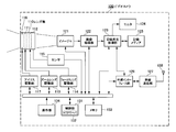
- FIG. 1 is a diagram illustrating a configuration example of an electronic device according to an example of an embodiment of the present disclosure.
- the video camera 100 includes an imager 121, and image light obtained by the attached lens unit 110 enters the imager 121.
- the imager 121 for example, a complementary metal oxide semiconductor (CMOS) image sensor or a charge coupled device (CCD) image sensor is used.
- CMOS complementary metal oxide semiconductor
- CCD charge coupled device
- the lens unit 110 includes a zoom lens 111 and a focus lens 112, and is a lens capable of zoom adjustment and focus adjustment.
- the zoom lens 111 is driven by a zoom lens driving unit 113.
- the focus lens 112 is driven by the focus lens driving unit 114.
- the video camera 100 also includes a sensor 115 that detects the positions of the zoom lens 111 and the focus lens 112.
- the lens unit 110 includes an iris 116.
- the iris 116 is driven by the iris driving unit 117.
- the driving of each lens by the zoom lens driving unit 113 and the focus lens driving unit 114 is performed according to a command from the control unit 131.
- the speed at which the driving units 113 and 114 move the positions of the zoom lens 111 and the focus lens 112 is set by a command from the control unit 131.
- the driving of the iris by the iris driving unit 117 is also performed by a command from the control unit 131. Further, the position data of the zoom lens 111 and the focus lens 112 detected by the sensor 115 is transmitted to the control unit 131.
- the imaging signal obtained by imaging by the imager 121 is supplied to the imaging processing unit 122.
- the imaging processing unit 122 performs various processes on the imaging signal and converts the imaging signal into an image signal having a predetermined format.
- the imaging processing unit 122 also executes white balance adjustment described later.
- the image signal output from the imaging processing unit 122 is supplied to the recording / reproducing unit 123, and the monitor 124 connected to the recording / reproducing unit 123 displays an image, and the recording medium 125 records the image signal.
- the recording medium 125 for example, a memory card incorporating a semiconductor memory, a hard disk drive device, or the like is used.
- the video camera 100 can output an image signal from an output terminal (not shown).
- a wireless communication unit 127 is connected to the recording / playback unit 123 via an external interface unit 126.
- the wireless communication unit 127 includes an antenna 128 and performs wireless communication with a partner within a short range of several meters to several tens of meters.
- the wireless communication unit 127 performs wireless communication based on, for example, a wireless LAN (Local Area Network) standard.
- the video camera 100 performs wireless communication by the wireless communication unit 127 and receives a command or the like for instructing an operation of a processing block in the video camera 100. In the video camera 100, the wireless communication unit 127 wirelessly transmits an image signal obtained by imaging.
- the partner with which the wireless communication unit 127 performs wireless communication may be an access point for wireless LAN in addition to the terminal device 200 described later.
- the control unit 131 that is an operation control unit that controls the operation of each unit of the video camera 100 communicates with each unit in the video camera 100 via an internal bus line.
- the memory 133 stores a program necessary for the control unit 131 to perform control processing.
- programs necessary for the video camera to function as a server are also stored in the memory 133.
- the control unit 131 forms a HTTP server 132 by executing a program necessary to function as this server.
- the HTTP server 132 communicates with a terminal device using an HTTP (HyperText Transfer Protocol) protocol.
- the external terminal device becomes a remote controller of the video camera 100 by the HTTP server 132 communicating with the external terminal device.
- the HTTP server 132 functions as a display control unit that controls the display of the operation screen, and the HTTP server 132 sends data necessary for generating the operation screen to be displayed to an external terminal device.
- the video camera 100 includes an operation unit 134.
- the operation unit 134 includes operation keys, a touch panel, and the like.
- an operation command arrives at the control unit 131, and the control unit 131 controls each unit to the operation state instructed.
- the control unit 131 similarly controls each unit to the instructed operation state. To do.
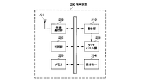
- FIG. 2 is a diagram illustrating a configuration example of the terminal device 200 with which the video camera 100 is a partner with which wireless communication is performed.
- the terminal device 200 may be a relatively small terminal device called a smartphone or a terminal device equipped with a relatively large display panel called a tablet terminal.
- the basic internal configuration of the terminal device 200 is the same, and the main difference is the size of the display panel.
- the terminal device 200 includes a wireless communication unit 202 to which an antenna 201 is connected.
- the wireless communication unit 202 performs wireless communication conforming to the wireless LAN standard. Wireless communication in the wireless communication unit 202 is executed under the control of the control unit 205.
- the control unit 205 controls display on the display unit 210.
- the terminal device 200 includes a touch panel unit 203, and the touch panel unit 203 detects that the surface of the display panel 211 (FIG. 4) included in the display unit 210 is touched with a finger or a pen.
- the touch panel unit 203 uses, for example, a capacitive type. A detection signal detected by the touch panel unit 203 is supplied to the control unit 205.
- the display unit 210 and the touch panel unit 203 may be configured integrally.
- the terminal device 200 includes an operation unit 204 on which operation keys and the like are arranged.
- the operation unit 204 may include a touch panel.
- the terminal device 200 performs wireless communication with the video camera 100, for example, and accesses the HTTP server 132 in the video camera 100, whereby the terminal device 200 becomes a remote controller of the video camera 100. That is, the control unit 205 of the terminal device 200 accesses the HTTP server 132 of the video camera 100, and the control unit 205 acquires data necessary for the display unit 210 to display the operation screen. At this time, for example, the control unit 205 accesses the HTTP server 132 using software (program) of a web browser. Then, an operation screen based on the acquired data is displayed on the display unit 210. The display data of the operation screen is generated by executing the web browser. This operation screen reflects the state of the video camera 100 in real time, and the operation screen displays values such as an adjustment state.
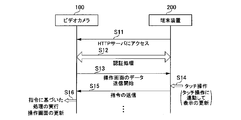
- FIG. 3 is a diagram illustrating a procedure when the wireless communication unit 127 of the video camera 100 and the wireless communication unit 202 of the terminal device 200 perform wireless communication.
- the control unit 205 of the terminal device 200 accesses the HTTP server 132 of the video camera 100 (step S11).
- the HTTP server 132 and the control unit 205 mutually perform a partner authentication process (step S12).
- the HTTP server 132 recognizes details about the terminal device 200 that has been accessed.
- the HTTP server 132 is an access from a terminal device having a relatively small display panel called a smartphone, or has a relatively large display panel called a tablet terminal. It is determined whether the access is from a terminal device. Based on this determination, the HTTP server 132 sets the operation screen to be transmitted to the terminal device 200 to the one corresponding to the screen specifications of the terminal device 200. Specific examples of each operation screen will be described later.
- the HTTP server 132 starts transmitting operation screen data to the terminal device 200 (step S13).
- the operation screen is displayed on the display unit 210.
- the control unit 205 detects a touch operation on the button or knob displayed on the operation screen (step S14)
- the control unit 205 generates an operation command based on the detected touch operation, and the operation command is HTTP. It is transmitted to the server 132 (step S15). Note that when the touch panel unit 203 detects a continuous user operation, an operation command is transmitted to the HTTP server 132 at regular intervals of, for example, about 100 milliseconds.
- the HTTP server 132 that has received the operation command transmits the operation command to the control unit 131, and the control unit 131 transmits a command corresponding to the operation command to each processing unit in the video camera 100 (step S16). Receiving this command, each processing unit in the video camera 100 executes processing based on the command. For example, when the HTTP server 132 receives a command related to a zoom operation, the control unit 131 transmits a zoom lens drive command based on the zoom operation command to the zoom lens drive unit 113. When the HTTP server 132 receives a command related to the focus operation, the control unit 131 transmits a focus lens drive command based on the focus operation command to the focus lens drive unit 114. In addition, the HTTP server 132 updates operation screen data transmitted to the terminal device 200 based on the received operation command.
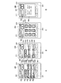
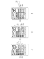
- FIG. 4 is a diagram illustrating an operation screen displayed on the display panel 211 of the terminal device 200.
- the example of FIG. 4 is a case of the terminal device 200 including a relatively small display panel 211 called a smartphone. In the case of this smartphone, four types of operation screens are displayed depending on the display mode. 4A to 4D show these four types of operation screens.
- the display panel 211 displays a status bar 310 indicating the state of the terminal device 200 itself at the upper end of the screen.
- the status bar 310 indicates the remaining battery level, the current time, the wireless communication state, and the like with graphics and numbers.
- the status bar 310 is updated by the control unit 205 of the terminal device 200. Display contents other than the status bar 310 are updated with data transmitted from the video camera 100 side.
- FIG. 4A is a lens operation screen. This lens operation screen is displayed when the lens tab 331 on the lower side of the screen is touched by the user. On the upper side of the lens operation screen, a recording key 321 and a lock key 322 are displayed.
- the recording key 321 is a key for instructing start and stop of recording.
- the lock key 322 is a key for instructing to lock and release the recording key 321.
- the lock key 322 is instructed to be locked or released when the user slides the touch position to the right.
- the recording key 321 and the lock key 322 are displayed in any of the four types of operation screen display modes.
- the lens operation screen displays an auto iris key 323, an auto focus key 324, an iris adjustment slider 340, a focus adjustment slider 350, and a zoom adjustment slider 360.
- the lens operation screen also displays an iris adjustment value display unit 342, a focus adjustment value display unit 352, and a zoom adjustment value display unit 362.
- These adjustment value display portions 342, 352, and 362 are disposed on the left side of the sliders 340, 350, and 360.
- the iris adjustment value display unit 342 displays the F value.
- the focus adjustment value display unit 352 and the zoom adjustment value display unit 362 display values corresponding to the lens positions detected by the sensor 115.
- Each value of the lens position is, for example, a value in the range of 0 to 99 so that a guideline for the focus adjustment state and the zoom adjustment state can be obtained.
- the adjustment value display units 352 and 362 may display those values.
- the video camera 100 automatically sets the adjustment value of the iris 116 of the lens unit 110.
- the video camera 100 automatically sets an adjustment value of the focus lens 112 of the lens unit 110.
- a knob 341 is displayed on the iris adjustment slider 340.
- the display position of the knob 341 on the iris adjustment slider 340 corresponds to the adjustment state of the iris 116.
- the iris adjustment slider 340 has a scale with a constant interval.
- the knob 341 shows a state of being arranged at substantially the center on the iris adjustment slider 340, but the position of the knob 341 on the iris adjustment slider 340 changes depending on the adjustment state of the iris 116. Therefore, the knob 341 is arranged at the center as shown in FIG. 4A, and the position of the knob 341 changes at any time depending on the adjustment state of the iris 116.
- the knob 341 on the iris adjustment slider 340 is displayed with a luminance lower than the original luminance. By displaying the knob 341 with such a low luminance, it is notified that the mode is incapable of user operation of the iris.
- the focus adjustment slider 350 displays a knob 351.
- the knob 351 is disposed at a default position serving as a central reference on the focus adjustment slider 350 when no user operation is performed.
- the focus lens 112 is driven in accordance with the direction and amount of movement of the knob 351.
- the display position of the knob 351 returns to the default position, and the drive of the focus lens 112 is stopped.
- the knob 351 on the focus adjustment slider 350 is displayed with a lower brightness than the original brightness. By displaying the knob 351 with low luminance in this way, it is notified that it is a mode in which a focus user operation cannot be performed.
- the zoom adjustment slider 360 displays a knob 361.
- This knob 361 is arranged at a specific position (default position) at the center on the zoom adjustment slider 360 when no user operation is performed.
- the zoom lens 111 is driven in accordance with the direction and amount of movement of the knob 361.
- the display position of the knob 361 returns to the default position, the drive of the zoom lens 111 is stopped, and the zoom lens 111 stops at the position when the touch operation is stopped.
- the focus adjustment slider 350 and the zoom adjustment slider 360 have only a mark indicating the default position without any regular scale. The operation when the knobs 351 and 361 are touched will be described in detail with reference to the flowchart of FIG.
- FIG. 4B is a white balance operation screen.
- This white balance operation screen is displayed when the white balance tab 332 on the lower side of the screen is touched by the user.
- the white balance operation screen displays an auto tracking white balance (ATW) key 325, an auto white balance (ATW) key 325, an R gain adjustment slider 370, and a B gain adjustment slider 380. Further, the white balance operation screen displays an R gain adjustment value display unit 372 and a B gain adjustment value display unit 382. These adjustment value display portions 372 and 382 are arranged on the left side of the B gain adjustment slider 380.
- the R gain adjustment slider 370 displays a knob 371, and the display position of the knob 371 on the R gain adjustment slider 370 corresponds to the R gain adjustment state.
- the B gain adjustment slider 380 displays a knob 381, and the display position of the knob 381 on the B gain adjustment slider 380 corresponds to the gain adjustment state.
- the R gain adjustment slider 370 and the B gain adjustment slider 380 have graduations at regular intervals.
- FIG. 4C is a playback operation screen. This playback operation screen is displayed when the playback tab 333 at the bottom of the screen is touched by the user. On the playback operation screen, a plurality of playback operation keys 391 for instructing various playback states and playback stop of the image signal recorded by the recording medium 125 of the video camera 100 are displayed.
- FIG. 4D is an information screen. This information screen is displayed when the information tab 334 at the bottom of the screen is touched by the user.
- the information screen includes an information section 392 that displays the model name and serial number of the video camera 100 of the communication partner.
- the information unit 392 also displays information about whether or not the video camera 100 can be remotely controlled.
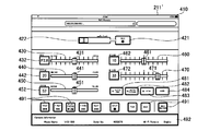
- FIG. 5 is an example of an operation screen when the terminal device 200 that performs wireless communication with the video camera 100 is a tablet terminal.
- this tablet terminal since a relatively large display panel 211 'is provided, all displays are performed on one operation screen. That is, in the case of a tablet terminal, a display in which the four operation screens for smartphones shown in FIGS. 4A to 4D are integrated into one is performed.
- a status bar 410 indicating the state of the terminal device 200 itself is displayed on the display panel 211 ′ at the upper end of the screen.
- a recording key 421 and a lock key 422 are displayed.
- an iris adjustment slider 430, a focus adjustment slider 440, a zoom adjustment slider 450, an R gain adjustment slider 460, and a B gain adjustment slider 470 are displayed on the display panel 211 ′.
- Each adjustment slider 430, 440, 450, 460, 470 displays knobs 431, 441, 451, 461, 471.
- knob 441 of the focus adjustment slider 440 and the knob 451 of the zoom adjustment slider 450 have the center on the slider set as a default position, and move from the default position only when the user performs a drag operation.
- adjustment value display sections 342, 442, 452, 462, 472 are displayed on the left side of each adjustment slider 430, 440, 450, 460, 470.
- an auto iris key 481, an auto focus key 482, an auto tracking white balance key 483, and an auto white balance key 484 are displayed on the display panel 211 ′. Further, a plurality of playback operation keys 491 and an information section 492 are displayed on the display panel 211 ′.
- Example 1 Example of processing during user operation: Example 1
- Example 1 a processing example (example 1) when the user operates by touching the operation screen will be described based on the flowchart of FIG.
- the same processing operation is performed when the user touches the knob 361 on the zoom adjustment slider 360 in the lens operation screen shown in FIG. 4A.
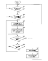
- the control unit 205 of the terminal device 200 determines whether or not there is a touch of a user's finger or the like on the knob 351 at the center default position of the focus adjustment slider 350 (step S21). If it is determined in this determination that the knob 351 is not touched, the control waits without performing focus adjustment. When it is determined in step S21 that there is a touch, the control unit 205 determines whether or not there is a drag operation for sliding the touch position along the focus adjustment slider 350 from the default position (center position) ( Step S22). If there is no drag operation, the control unit 205 returns to the determination in step S21.
- step S22 If it is determined in step S22 that there is a drag operation, the control unit 205 changes the display position on the focus adjustment slider 350 of the knob 351 following the change in the touch position where the drag operation is performed. (Step S23). Further, the control unit 205 generates a command for instructing the direction and speed based on the direction in which the drag operation has been performed from the center and the amount of sliding by the drag operation, and transmits the command to the video camera 100 side (step S24). ). The command is transmitted at a constant cycle (for example, 100 milliseconds) while the touch operation is continued.
- a constant cycle for example, 100 milliseconds
- the control unit 205 determines whether or not the user continues to touch the knob 351 (step S25).
- the control unit 205 determines whether or not there is a change in the touch position (step S26), and when there is no change in the touch position, the determination in step S25.
- the control unit 205 returns to the determination in step S23.
- the transmission of the command from the control unit 205 to the video camera 100 is stopped (step S27). Further, based on an instruction from the HTTP server 132 on the video camera 100 side, the display position of the knob 351 returns to the center fault position (step S28). Thereafter, the control unit 205 returns to the determination in step S21.
- FIG. 7A shows a state where the user's finger f1 has touched the knob 351 at the default position of the center of the focus adjustment slider 350.
- FIG. When the finger f1 touches the display position of the knob 351, the control unit 205 shifts from step S21 to step S22.
- the display example of FIG. 7B shows a state when the touch position of the finger f2 slides to the right along the focus adjustment slider 350 with the default position as a base point.
- the focus adjustment position of the focus lens 112 is in the + direction (far here), and a focus adjustment command with a speed corresponding to the slide amount is transmitted from the terminal device 200 to the video camera 100.
- the focus adjustment position of the focus lens 112 is a focus adjustment command in the negative direction (here, near).
- the touch position of the user's finger changes, the speed and direction of the focus adjustment command change according to the touch position.
- FIG. 7C shows a state in which the user's finger f3 is away from the screen. As soon as the user's finger f3 leaves the screen, transmission of the focus adjustment command stops. Then, as shown in FIG. 7C, the position of the knob 351 automatically returns to the default position. At this time, the knob 351 is gradually moved from the slide position shown in FIG. 7B to the default position over a period of time (for example, about 0.5 seconds). As described above, when the knob 351 returns to the original default position after taking some time, the movement of the knob 351 is notified to the user in an easy-to-understand manner, and a good display form is obtained.
- a period of time for example, about 0.5 seconds
- the video camera 100 can obtain the same operability as when the mechanical adjustment lever is provided using the touch panel.
- the knob 351 may immediately return to the original default position. Further, the speed at which the knob 351 returns to the original default position by mode switching by a user operation may be freely adjusted.
- 7C illustrates the state where the knob 351 returns to the default position when the user's finger f3 is separated from the screen. However, the position on the screen touched by the user's finger f3 is other than the display position of the knob 351. The knob 351 also returns to the original default position when.
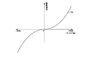
- FIG. 8 shows the amount of movement on the screen when the knob 351 is moved by a touch operation from the default position (center position) on the focus adjustment slider 350, and the driving speed of the focus lens 112 by the focus lens driving unit 114.
- the horizontal axis of FIG. 8 shows the shift amount (shift distance) of the knob 351 from the center position (position shown as 0).
- the vertical axis in FIG. 8 indicates the driving speed of the focus lens 112 set by a command at each shift amount.
- the driving direction of the focus lens 112 is reversed with respect to the center position.
- the characteristic Va in FIG. 8 the driving speed is gradually increased as the distance from the center position becomes longer.
- the speed change characteristic Va of the curve shown in FIG. 8 is one example, and may be a characteristic in which the shift amount and the drive speed change linearly, for example.
- the operation when the user operates the focus adjustment slider 350 on the operation screen has been described.
- the knob 361 on the zoom adjustment slider 360 is also displayed at the center position when there is no user operation.
- the terminal device 200 transmits a zoom adjustment command for instructing the driving speed and driving direction of the zoom lens 111.
- the terminal device 200 performs a process of stopping outputting the zoom adjustment command and returning the display position of the knob 361 to the center position.
- the knobs 341, 371, and 381 are at positions indicating the adjustment state at that time. In the case of the example of FIG. 4, it can be distinguished from the presence or absence of a scale on the slider that the knob returns to the default position.
- the same processing is applied to the operation on the operation screen for the tablet terminal shown in FIG. That is, the processing shown in the flowchart of FIG. 6 is performed on the focus adjustment slider 440 and the zoom adjustment slider 450 in the operation screen for the tablet terminal shown in FIG.
- the knobs 431, 461, and 471 are positions indicating the adjustment state at that time.
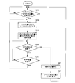
- Example 2 Next, based on the flowchart in FIG. 9 and the display example in FIG. 10, a processing example (example 2) when the user touches the operation screen and operates is described.
- the same step number is assigned to the same process as that of the flowchart of FIG.
- Example 1 first, the user touches the knob 351 at the default position on the focus adjustment slider 350 so that the knob 351 can be moved.
- Example 2 when the user touches an arbitrary position on the focus adjustment slider 350 in a state where the knob 351 is disposed at the default position on the focus adjustment slider 350, the touch is performed. The knob 351 is moved to the position.
- the control unit 205 of the terminal device 200 determines whether or not there is a touch of a user's finger or the like at any position of the focus adjustment slider 350 (step S31). If it is determined in this determination that there is no touch at any position of the focus adjustment slider 350, the process waits without performing focus adjustment. If it is determined in step S31 that there is a touch, the control unit 205 changes the display position of the knob 351 on the focus adjustment slider 350 to touch (step S23). At this time, the knob 351 is moved immediately from the default position to the touch position, for example. Alternatively, the knob 351 may move from the default position to the touch position over a certain period of time.
- the processing after step S23 is the same as the flowchart of FIG.
- FIG. 10A shows a state where the user's finger f11 touches a specific position other than the center on the focus adjustment slider 350.
- the control unit 205 performs touch detection in step S31.
- the operation screen changes to the state shown in FIG. 10B. That is, the display position of the knob 351 changes to the touch position t on the focus adjustment slider 350. Then, a direction and speed focus adjustment command corresponding to the position of the knob 351 at this time is transmitted from the terminal device 200 to the video camera 100.
- the processing when the user's finger leaves the operation screen is the same as in Example 1 shown in FIG. That is, as shown in FIG. 10C, at the same time as the user's finger f12 leaves the screen, transmission of the focus adjustment command is stopped. Then, as shown in FIG. 10C, the position of the knob 351 automatically returns to the default position. At this time, the knob 351 gradually moves from the slide position shown in FIG. 10B to the default position over a predetermined time. Alternatively, the knob 351 immediately returns to the original default position when the user's finger f12 leaves the screen.
- Example 2 In the case of Example 2 described with reference to FIGS. 9 and 10, there is no need to slide the knob 351 at the beginning of the operation. For this reason, in the case of Example 2, operation quicker than Example 1 is attained. However, since the operation is performed immediately when a finger touches the position on the focus adjustment slider 350, an erroneous operation may be performed. For this reason, it is preferable that the processing in Example 1 and the processing in Example 2 can be selected by a user operation. That is, when the first mode is selected so that the operation mode can be selected, the control unit 205 executes the process of the flowchart of FIG. 6, and when the second mode is selected, the control unit 205 The process of the flowchart of FIG. 9 is executed. By being able to select in this way, the terminal device 200 can obtain the operability that the user likes.
- the technique of the present disclosure is applied to the processing when the display panel 211 of the terminal device 200 that remotely controls the video camera 100 displays the operation screen.
- the operation unit 134 of the video camera 100 may include a display panel with a touch panel, and a similar operation screen may be displayed on the display panel of the video camera body. In this case, for example, the operation screen is displayed under the control of the control unit 131 of the video camera 100.
- the video camera 100 includes the control unit 131 that functions as the HTTP server 132, and the terminal device 200 is connected to the HTTP server 132 by using a web browser program that the terminal device 200 has. I tried to access it.
- the terminal device or the computer device may have a dedicated program for remote control, and the device in which the program is installed may operate as a remote controller. In this case, the program may execute the procedure shown in FIGS.
- the HTTP server 132 provided in the control unit 131 is also an example, and may be a server that performs communication using other protocols. For example, a server that can be accessed by executing a dedicated program for remote control may be prepared.
- the technique of the present disclosure is applied to the display of the operation screen when the zoom lens 111 and the focus lens 112 of the lens unit 110 of the video camera 100 are adjusted.
- the operation screen may be touched using a dedicated touch pen or the like.
- a knob or the like on the operation screen may be selected by a method other than the touch operation.
- a pointing device such as a mouse is connected to the terminal device 200. Then, when the knob 351 or the like of the focus adjustment slider 350 is selected by the setting of the cursor position on the screen by the pointing device and the drag operation after the click operation, the processing shown in the flowchart of FIG. 6 is performed. By doing in this way, the process of this indication is applicable also to the terminal device and computer apparatus in which a display part is not provided with a touch panel.
- this indication can also take the following structures.
- a processing unit in which the adjustment position or numerical value can be set A display control unit that displays a knob that moves on the slider in response to a user operation as an adjustment position or numerical value setting screen, and sets the position of the knob to a default position on the slider when there is no user operation.
- An electronic apparatus comprising: an operation control unit that changes the adjustment position or a numerical value in response to a change in the position of the knob by a user operation on a setting screen displayed by the control of the display control unit.
- the processing unit is a lens driving unit that sets a zoom position of a zoom lens or a focus position of a focus lens.
- the setting screen displayed by the control of the display control unit is a drag operation on the slider based on the position where the touch detection or click operation is performed after the touch detection or click operation of the knob at the default position.
- the operation control unit immediately stops changing the adjustment position or numerical value,
- the display control unit returns a display position of the knob to a default position on the slider over a predetermined time.
- the setting screen displayed by the control of the display control unit changes the position of the knob to the detected position by detecting a touch on the slider or detecting a click operation.
- any one of (1) to (4) The electronic device as described in the paragraph.
- (6) The electronic device according to any one of (1) to (5), wherein the operation control unit changes the adjustment position or a parameter change speed according to an amount of movement of the knob from the default position.
- the display control unit is a server function unit that displays the setting screen on a display unit included in an external terminal device that is performing communication.
- (8) As a setting screen for setting an adjustment position or a numerical value based on a user operation, a knob that is moved on the slider by a user operation is displayed, and when there is no user operation, the position of the knob is displayed on the slider.
- DESCRIPTION OF SYMBOLS 100 Video camera, 110 ... Lens part, 111 ... Zoom lens, 112 ... Focus lens, 113 ... Zoom lens drive part, 114 ... Focus lens drive part, 115 ... Sensor, 121 ... Imager, 122 ... Imaging process part, 123 ... Recording / playback unit 124 ... monitor 125 recording medium 126 external interface unit 128 wireless communication unit 128 antenna 131 control unit 132 HTTP server 133 memory 134 operation unit 200 Terminal device 201 ... Antenna 202 ... Wireless communication unit 203 ... Touch panel unit 204 ... Operation key 205 ... Control unit 206 ... Memory 210 ... Display unit 211, 211 '... Display panel 340 ...
- Iris adjustment Slider 341, knob, 342, iris adjustment value display section, 350 Focus adjustment slider, 351 ... knob, 352 ... Focus adjustment value display section, 360 ... Zoom adjustment slider, 361 ... Knob, 362 ... Zoom adjustment value display section, 430 ... Iris adjustment slider, 431 ... Knob, 432 ... Iris Adjustment value display unit, 440... Focus adjustment slider, 441... Knob, 442... Focus adjustment value display unit, 450... Zoom adjustment slider, 451.
Landscapes
- Engineering & Computer Science (AREA)
- Multimedia (AREA)
- Signal Processing (AREA)
- General Engineering & Computer Science (AREA)
- Theoretical Computer Science (AREA)
- Human Computer Interaction (AREA)
- General Physics & Mathematics (AREA)
- Physics & Mathematics (AREA)
- Studio Devices (AREA)
- Camera Bodies And Camera Details Or Accessories (AREA)
- Indication In Cameras, And Counting Of Exposures (AREA)
- User Interface Of Digital Computer (AREA)
- Lens Barrels (AREA)
Priority Applications (5)
| Application Number | Priority Date | Filing Date | Title |
|---|---|---|---|
| JP2014531486A JP6070708B2 (ja) | 2012-08-20 | 2013-07-18 | 電子機器、機器操作方法およびプログラム |
| ES13830845T ES2702356T3 (es) | 2012-08-20 | 2013-07-18 | Equipo electrónico, método de operación del equipo, y programa |
| US14/421,572 US10331320B2 (en) | 2012-08-20 | 2013-07-18 | Electronic apparatus, apparatus operation method, and program |
| EP13830845.7A EP2887200B1 (en) | 2012-08-20 | 2013-07-18 | Electronic device, device operation method and program |
| EP18206821.3A EP3480684B1 (en) | 2012-08-20 | 2013-07-18 | Electronic apparatus, apparatus operation method, and program |
Applications Claiming Priority (2)
| Application Number | Priority Date | Filing Date | Title |
|---|---|---|---|
| JP2012-181543 | 2012-08-20 | ||
| JP2012181543 | 2012-08-20 |
Related Child Applications (1)
| Application Number | Title | Priority Date | Filing Date |
|---|---|---|---|
| US14/421,572 Continuation US10331320B2 (en) | 2012-08-20 | 2013-07-18 | Electronic apparatus, apparatus operation method, and program |
Publications (1)
| Publication Number | Publication Date |
|---|---|
| WO2014030290A1 true WO2014030290A1 (ja) | 2014-02-27 |
Family
ID=50149622
Family Applications (1)
| Application Number | Title | Priority Date | Filing Date |
|---|---|---|---|
| PCT/JP2013/004395 Ceased WO2014030290A1 (ja) | 2012-08-20 | 2013-07-18 | 電子機器、機器操作方法およびプログラム |
Country Status (5)
| Country | Link |
|---|---|
| US (1) | US10331320B2 (enExample) |
| EP (2) | EP2887200B1 (enExample) |
| JP (2) | JP6070708B2 (enExample) |
| ES (2) | ES2702356T3 (enExample) |
| WO (1) | WO2014030290A1 (enExample) |
Cited By (2)
| Publication number | Priority date | Publication date | Assignee | Title |
|---|---|---|---|---|
| JP2018133673A (ja) * | 2017-02-14 | 2018-08-23 | キヤノン株式会社 | 撮像装置、その制御方法、プログラム |
| JP2018156353A (ja) * | 2017-03-17 | 2018-10-04 | キヤノン株式会社 | 情報処理装置、情報処理方法およびプログラム |
Families Citing this family (8)
| Publication number | Priority date | Publication date | Assignee | Title |
|---|---|---|---|---|
| KR20160063812A (ko) * | 2014-11-27 | 2016-06-07 | 삼성전자주식회사 | 화면 구성 방법, 전자 장치 및 저장 매체 |
| JP2016162132A (ja) * | 2015-02-27 | 2016-09-05 | ソニー株式会社 | 情報処理装置、情報処理方法、およびプログラム |
| USD784394S1 (en) * | 2015-09-11 | 2017-04-18 | Under Armour, Inc. | Display screen with graphical user interface |
| SG10201507782WA (en) * | 2015-09-18 | 2017-04-27 | Paul Michael Whiten | User interface for searching a large data set |
| AT517687B1 (de) * | 2015-09-23 | 2017-04-15 | Omicron Electronics Gmbh | Prüfvorrichtung und Verfahren zum Steuern einer Prüfvorrichtung |
| US10863267B2 (en) * | 2015-11-10 | 2020-12-08 | Savant Systems, Inc. | Volume control for audio/video devices |
| EP3970603A4 (en) | 2019-05-16 | 2023-07-12 | Hoya Corporation | Endoscope processor, program, and information processing method |
| JP2023044327A (ja) | 2021-09-17 | 2023-03-30 | パナソニックIpマネジメント株式会社 | 撮像装置 |
Citations (4)
| Publication number | Priority date | Publication date | Assignee | Title |
|---|---|---|---|---|
| JPH06273658A (ja) | 1993-01-21 | 1994-09-30 | Sony Corp | ビデオカメラ |
| JP2011232684A (ja) * | 2010-04-30 | 2011-11-17 | Canon Inc | レンズ装置 |
| JP2012090157A (ja) * | 2010-10-21 | 2012-05-10 | Canon Inc | 表示制御装置、表示制御方法 |
| JP2013037556A (ja) * | 2011-08-09 | 2013-02-21 | Casio Comput Co Ltd | 電子機器、及びプログラム |
Family Cites Families (17)
| Publication number | Priority date | Publication date | Assignee | Title |
|---|---|---|---|---|
| JPH07234981A (ja) | 1994-02-24 | 1995-09-05 | Mitsubishi Electric Corp | プラント操作情報処理装置 |
| JPH11212726A (ja) * | 1998-01-29 | 1999-08-06 | Omron Corp | 入力装置 |
| JP2001075712A (ja) | 1999-08-31 | 2001-03-23 | Sony Corp | 情報処理装置及び情報処理方法並びにプログラム格納媒体 |
| JP2001350579A (ja) | 2000-06-07 | 2001-12-21 | Seiko Epson Corp | 携帯情報機器 |
| JP2005321896A (ja) * | 2004-05-06 | 2005-11-17 | Canon Inc | 表示制御方法及び表示制御装置 |
| JP4546202B2 (ja) * | 2004-09-28 | 2010-09-15 | キヤノン株式会社 | 映像受信装置とその制御方法とプログラム及び記憶媒体 |
| JP2006338406A (ja) | 2005-06-02 | 2006-12-14 | Sharp Corp | 通信端末装置、情報処理装置、通信システム、映像表示システム、通信端末制御方法、情報処理方法、通信端末制御プログラム、情報処理プログラムおよび記録媒体 |
| JP2007065385A (ja) | 2005-08-31 | 2007-03-15 | Canon Inc | 光学機器 |
| JP4612886B2 (ja) | 2005-10-26 | 2011-01-12 | キヤノン株式会社 | レンズ装置および撮像システム |
| JP4652248B2 (ja) | 2006-02-22 | 2011-03-16 | 富士フイルム株式会社 | 撮影システム、撮影制御方法、及び撮影装置 |
| JP5339114B2 (ja) * | 2007-10-12 | 2013-11-13 | 株式会社ニコン | 顕微鏡 |
| US20110027687A1 (en) * | 2009-07-31 | 2011-02-03 | Asahi Glass Company, Limited | Electrolyte material, liquid composition and membrane/electrode assembly for polymer electrolyte fuel cell |
| JP5237325B2 (ja) * | 2010-04-28 | 2013-07-17 | 株式会社スクウェア・エニックス | ビデオゲーム処理装置、ビデオゲーム処理方法、およびビデオゲーム処理プログラム |
| JP5622447B2 (ja) | 2010-06-11 | 2014-11-12 | 任天堂株式会社 | 情報処理プログラム、情報処理装置、情報処理システム及び情報処理方法 |
| JP5464083B2 (ja) * | 2010-07-07 | 2014-04-09 | ソニー株式会社 | 情報処理装置、情報処理方法およびプログラム |
| JP2012113110A (ja) | 2010-11-24 | 2012-06-14 | Canon Inc | 電子機器 |
| US20130014057A1 (en) * | 2011-07-07 | 2013-01-10 | Thermal Matrix USA, Inc. | Composite control for a graphical user interface |
-
2013
- 2013-07-18 ES ES13830845T patent/ES2702356T3/es active Active
- 2013-07-18 ES ES18206821T patent/ES2903554T3/es active Active
- 2013-07-18 JP JP2014531486A patent/JP6070708B2/ja active Active
- 2013-07-18 EP EP13830845.7A patent/EP2887200B1/en not_active Not-in-force
- 2013-07-18 EP EP18206821.3A patent/EP3480684B1/en active Active
- 2013-07-18 US US14/421,572 patent/US10331320B2/en active Active
- 2013-07-18 WO PCT/JP2013/004395 patent/WO2014030290A1/ja not_active Ceased
-
2016
- 2016-12-28 JP JP2016255254A patent/JP6384541B2/ja not_active Expired - Fee Related
Patent Citations (4)
| Publication number | Priority date | Publication date | Assignee | Title |
|---|---|---|---|---|
| JPH06273658A (ja) | 1993-01-21 | 1994-09-30 | Sony Corp | ビデオカメラ |
| JP2011232684A (ja) * | 2010-04-30 | 2011-11-17 | Canon Inc | レンズ装置 |
| JP2012090157A (ja) * | 2010-10-21 | 2012-05-10 | Canon Inc | 表示制御装置、表示制御方法 |
| JP2013037556A (ja) * | 2011-08-09 | 2013-02-21 | Casio Comput Co Ltd | 電子機器、及びプログラム |
Non-Patent Citations (1)
| Title |
|---|
| See also references of EP2887200A4 |
Cited By (2)
| Publication number | Priority date | Publication date | Assignee | Title |
|---|---|---|---|---|
| JP2018133673A (ja) * | 2017-02-14 | 2018-08-23 | キヤノン株式会社 | 撮像装置、その制御方法、プログラム |
| JP2018156353A (ja) * | 2017-03-17 | 2018-10-04 | キヤノン株式会社 | 情報処理装置、情報処理方法およびプログラム |
Also Published As
| Publication number | Publication date |
|---|---|
| JP6070708B2 (ja) | 2017-02-01 |
| EP2887200A4 (en) | 2016-05-11 |
| EP3480684A1 (en) | 2019-05-08 |
| JP2017076433A (ja) | 2017-04-20 |
| ES2903554T3 (es) | 2022-04-04 |
| US20150227303A1 (en) | 2015-08-13 |
| ES2702356T3 (es) | 2019-02-28 |
| EP2887200A1 (en) | 2015-06-24 |
| JPWO2014030290A1 (ja) | 2016-07-28 |
| JP6384541B2 (ja) | 2018-09-05 |
| US10331320B2 (en) | 2019-06-25 |
| EP3480684B1 (en) | 2021-12-15 |
| EP2887200B1 (en) | 2018-11-28 |
Similar Documents
| Publication | Publication Date | Title |
|---|---|---|
| JP6384541B2 (ja) | 電子機器、機器操作方法およびプログラム | |
| JP6103807B2 (ja) | 表示制御装置、その制御方法及びプログラム | |
| CN109479096B (zh) | 电子设备及其控制方法和记录介质 | |
| US9979881B2 (en) | Imaging control apparatus and method for controlling the same | |
| JP6590666B2 (ja) | 電子機器およびその制御方法 | |
| KR20130092196A (ko) | 카메라 셔터키 표시 장치 및 방법 | |
| CN110661946B (zh) | 电子设备、电子设备的控制方法和计算机可读介质 | |
| CN104111720A (zh) | 电子设备控制方法、装置及电子设备 | |
| JP2017123515A (ja) | 電子機器およびその制御方法 | |
| JP2018036802A (ja) | 電子機器およびその制御方法 | |
| US10904442B2 (en) | Image sensing apparatus with improved user operability when performing an enlarged display of a live view image and control method of image sensing apparatus | |
| JP6112985B2 (ja) | 表示制御装置、方法及びプログラム並びに記憶媒体 | |
| US12273615B2 (en) | Lens system for reducing a shake induced by a touch-down operation | |
| EP3413183B1 (en) | Electronic apparatus and method for controlling the same | |
| JP6012351B2 (ja) | 画像処理装置、その制御方法及びプログラム | |
| JP2020197976A (ja) | 電子機器、電子機器の制御方法、プログラム、記憶媒体 | |
| JP2021028785A (ja) | 電子機器および電子機器の制御方法 | |
| CN121325358A (zh) | 镜头系统及程序 | |
| JP2015012595A (ja) | コンテンツ管理装置、コンテンツ閲覧装置及びそれらの制御方法、並びに、プログラム | |
| CN116782027A (zh) | 电子装置、控制方法和存储介质 | |
| JP2021068155A (ja) | 電子機器及びその制御方法 |
Legal Events
| Date | Code | Title | Description |
|---|---|---|---|
| 121 | Ep: the epo has been informed by wipo that ep was designated in this application |
Ref document number: 13830845 Country of ref document: EP Kind code of ref document: A1 |
|
| ENP | Entry into the national phase |
Ref document number: 2014531486 Country of ref document: JP Kind code of ref document: A |
|
| WWE | Wipo information: entry into national phase |
Ref document number: 2013830845 Country of ref document: EP |
|
| WWE | Wipo information: entry into national phase |
Ref document number: 14421572 Country of ref document: US |
|
| NENP | Non-entry into the national phase |
Ref country code: DE |