WO2014027554A1 - 液面表示装置、ターボ圧縮機及びターボ冷凍機 - Google Patents
液面表示装置、ターボ圧縮機及びターボ冷凍機 Download PDFInfo
- Publication number
- WO2014027554A1 WO2014027554A1 PCT/JP2013/070184 JP2013070184W WO2014027554A1 WO 2014027554 A1 WO2014027554 A1 WO 2014027554A1 JP 2013070184 W JP2013070184 W JP 2013070184W WO 2014027554 A1 WO2014027554 A1 WO 2014027554A1
- Authority
- WO
- WIPO (PCT)
- Prior art keywords
- liquid level
- liquid
- display device
- level display
- turbo compressor
- Prior art date
- Legal status (The legal status is an assumption and is not a legal conclusion. Google has not performed a legal analysis and makes no representation as to the accuracy of the status listed.)
- Ceased
Links
Images


Classifications
-
- G—PHYSICS
- G01—MEASURING; TESTING
- G01F—MEASURING VOLUME, VOLUME FLOW, MASS FLOW OR LIQUID LEVEL; METERING BY VOLUME
- G01F23/00—Indicating or measuring liquid level or level of fluent solid material, e.g. indicating in terms of volume or indicating by means of an alarm
- G01F23/02—Indicating or measuring liquid level or level of fluent solid material, e.g. indicating in terms of volume or indicating by means of an alarm by gauge glasses or other apparatus involving a window or transparent tube for directly observing the level to be measured or the level of a liquid column in free communication with the main body of the liquid
-
- F—MECHANICAL ENGINEERING; LIGHTING; HEATING; WEAPONS; BLASTING
- F04—POSITIVE - DISPLACEMENT MACHINES FOR LIQUIDS; PUMPS FOR LIQUIDS OR ELASTIC FLUIDS
- F04D—NON-POSITIVE-DISPLACEMENT PUMPS
- F04D29/00—Details, component parts, or accessories
- F04D29/06—Lubrication
- F04D29/063—Lubrication specially adapted for elastic fluid pumps
-
- F—MECHANICAL ENGINEERING; LIGHTING; HEATING; WEAPONS; BLASTING
- F04—POSITIVE - DISPLACEMENT MACHINES FOR LIQUIDS; PUMPS FOR LIQUIDS OR ELASTIC FLUIDS
- F04D—NON-POSITIVE-DISPLACEMENT PUMPS
- F04D17/00—Radial-flow pumps, e.g. centrifugal pumps; Helico-centrifugal pumps
- F04D17/08—Centrifugal pumps
- F04D17/10—Centrifugal pumps for compressing or evacuating
- F04D17/12—Multi-stage pumps
- F04D17/122—Multi-stage pumps the individual rotor discs being, one for each stage, on a common shaft and axially spaced, e.g. conventional centrifugal multi- stage compressors
-
- F—MECHANICAL ENGINEERING; LIGHTING; HEATING; WEAPONS; BLASTING
- F04—POSITIVE - DISPLACEMENT MACHINES FOR LIQUIDS; PUMPS FOR LIQUIDS OR ELASTIC FLUIDS
- F04D—NON-POSITIVE-DISPLACEMENT PUMPS
- F04D25/00—Pumping installations or systems
- F04D25/02—Units comprising pumps and their driving means
- F04D25/06—Units comprising pumps and their driving means the pump being electrically driven
- F04D25/0606—Units comprising pumps and their driving means the pump being electrically driven the electric motor being specially adapted for integration in the pump
-
- F—MECHANICAL ENGINEERING; LIGHTING; HEATING; WEAPONS; BLASTING
- F25—REFRIGERATION OR COOLING; COMBINED HEATING AND REFRIGERATION SYSTEMS; HEAT PUMP SYSTEMS; MANUFACTURE OR STORAGE OF ICE; LIQUEFACTION SOLIDIFICATION OF GASES
- F25B—REFRIGERATION MACHINES, PLANTS OR SYSTEMS; COMBINED HEATING AND REFRIGERATION SYSTEMS; HEAT PUMP SYSTEMS
- F25B1/00—Compression machines, plants or systems with non-reversible cycle
- F25B1/005—Compression machines, plants or systems with non-reversible cycle of the single unit type
-
- F—MECHANICAL ENGINEERING; LIGHTING; HEATING; WEAPONS; BLASTING
- F25—REFRIGERATION OR COOLING; COMBINED HEATING AND REFRIGERATION SYSTEMS; HEAT PUMP SYSTEMS; MANUFACTURE OR STORAGE OF ICE; LIQUEFACTION SOLIDIFICATION OF GASES
- F25B—REFRIGERATION MACHINES, PLANTS OR SYSTEMS; COMBINED HEATING AND REFRIGERATION SYSTEMS; HEAT PUMP SYSTEMS
- F25B1/00—Compression machines, plants or systems with non-reversible cycle
- F25B1/04—Compression machines, plants or systems with non-reversible cycle with compressor of rotary type
- F25B1/053—Compression machines, plants or systems with non-reversible cycle with compressor of rotary type of turbine type
-
- F—MECHANICAL ENGINEERING; LIGHTING; HEATING; WEAPONS; BLASTING
- F25—REFRIGERATION OR COOLING; COMBINED HEATING AND REFRIGERATION SYSTEMS; HEAT PUMP SYSTEMS; MANUFACTURE OR STORAGE OF ICE; LIQUEFACTION SOLIDIFICATION OF GASES
- F25B—REFRIGERATION MACHINES, PLANTS OR SYSTEMS; COMBINED HEATING AND REFRIGERATION SYSTEMS; HEAT PUMP SYSTEMS
- F25B9/00—Compression machines, plants or systems, in which the refrigerant is air or other gas of low boiling point
- F25B9/002—Compression machines, plants or systems, in which the refrigerant is air or other gas of low boiling point characterised by the refrigerant
-
- F—MECHANICAL ENGINEERING; LIGHTING; HEATING; WEAPONS; BLASTING
- F25—REFRIGERATION OR COOLING; COMBINED HEATING AND REFRIGERATION SYSTEMS; HEAT PUMP SYSTEMS; MANUFACTURE OR STORAGE OF ICE; LIQUEFACTION SOLIDIFICATION OF GASES
- F25B—REFRIGERATION MACHINES, PLANTS OR SYSTEMS; COMBINED HEATING AND REFRIGERATION SYSTEMS; HEAT PUMP SYSTEMS
- F25B2339/00—Details of evaporators; Details of condensers
- F25B2339/02—Details of evaporators
- F25B2339/024—Evaporators with refrigerant in a vessel in which is situated a heat exchanger
-
- F—MECHANICAL ENGINEERING; LIGHTING; HEATING; WEAPONS; BLASTING
- F25—REFRIGERATION OR COOLING; COMBINED HEATING AND REFRIGERATION SYSTEMS; HEAT PUMP SYSTEMS; MANUFACTURE OR STORAGE OF ICE; LIQUEFACTION SOLIDIFICATION OF GASES
- F25B—REFRIGERATION MACHINES, PLANTS OR SYSTEMS; COMBINED HEATING AND REFRIGERATION SYSTEMS; HEAT PUMP SYSTEMS
- F25B2339/00—Details of evaporators; Details of condensers
- F25B2339/04—Details of condensers
- F25B2339/047—Water-cooled condensers
-
- F—MECHANICAL ENGINEERING; LIGHTING; HEATING; WEAPONS; BLASTING
- F25—REFRIGERATION OR COOLING; COMBINED HEATING AND REFRIGERATION SYSTEMS; HEAT PUMP SYSTEMS; MANUFACTURE OR STORAGE OF ICE; LIQUEFACTION SOLIDIFICATION OF GASES
- F25B—REFRIGERATION MACHINES, PLANTS OR SYSTEMS; COMBINED HEATING AND REFRIGERATION SYSTEMS; HEAT PUMP SYSTEMS
- F25B2400/00—Component parts or details not otherwise provided for in this subclass
- F25B2400/13—Economisers
-
- F—MECHANICAL ENGINEERING; LIGHTING; HEATING; WEAPONS; BLASTING
- F25—REFRIGERATION OR COOLING; COMBINED HEATING AND REFRIGERATION SYSTEMS; HEAT PUMP SYSTEMS; MANUFACTURE OR STORAGE OF ICE; LIQUEFACTION SOLIDIFICATION OF GASES
- F25B—REFRIGERATION MACHINES, PLANTS OR SYSTEMS; COMBINED HEATING AND REFRIGERATION SYSTEMS; HEAT PUMP SYSTEMS
- F25B2500/00—Problems to be solved
- F25B2500/16—Lubrication
-
- F—MECHANICAL ENGINEERING; LIGHTING; HEATING; WEAPONS; BLASTING
- F25—REFRIGERATION OR COOLING; COMBINED HEATING AND REFRIGERATION SYSTEMS; HEAT PUMP SYSTEMS; MANUFACTURE OR STORAGE OF ICE; LIQUEFACTION SOLIDIFICATION OF GASES
- F25B—REFRIGERATION MACHINES, PLANTS OR SYSTEMS; COMBINED HEATING AND REFRIGERATION SYSTEMS; HEAT PUMP SYSTEMS
- F25B2700/00—Sensing or detecting of parameters; Sensors therefor
- F25B2700/03—Oil level
-
- F—MECHANICAL ENGINEERING; LIGHTING; HEATING; WEAPONS; BLASTING
- F25—REFRIGERATION OR COOLING; COMBINED HEATING AND REFRIGERATION SYSTEMS; HEAT PUMP SYSTEMS; MANUFACTURE OR STORAGE OF ICE; LIQUEFACTION SOLIDIFICATION OF GASES
- F25B—REFRIGERATION MACHINES, PLANTS OR SYSTEMS; COMBINED HEATING AND REFRIGERATION SYSTEMS; HEAT PUMP SYSTEMS
- F25B31/00—Compressor arrangements
- F25B31/002—Lubrication
-
- G—PHYSICS
- G01—MEASURING; TESTING
- G01F—MEASURING VOLUME, VOLUME FLOW, MASS FLOW OR LIQUID LEVEL; METERING BY VOLUME
- G01F23/00—Indicating or measuring liquid level or level of fluent solid material, e.g. indicating in terms of volume or indicating by means of an alarm
Definitions
- the present invention relates to a liquid level display device, a turbo compressor, and a turbo refrigerator.
- This application claims priority based on Japanese Patent Application No. 2012-179541 for which it applied to Japan on August 13, 2012, and uses the content here.
- a turbo refrigerator having a turbo compressor that compresses and discharges a refrigerant by rotating an impeller with an electric motor
- a turbo compressor lubricating oil is supplied from an oil tank to sliding parts such as a bearing of a rotating shaft of an electric motor and a bearing of a rotating shaft of an impeller.
- a liquid level display device having a site glass for observing the liquid level is provided in the oil tank.
- a differential pressure type liquid level gauge is described as one of devices for observing the liquid level.
- This differential pressure type liquid level gauge has a configuration suitable for a liquefied gas tank, and the tip portion including the open end of the high pressure side pressure guiding tube is horizontal or substantially inside the vicinity of the bottom of the liquefied gas tank. It is inserted horizontally.
- the oil tank of the turbo compressor has a small amount of liquid storage compared to the liquefied gas tank, and it is difficult to observe minute changes in the liquid level due to oil leakage with the differential pressure type level gauge. For example, when the oil tank is placed below the gear unit and oil pours down from the gear unit to the liquid level, the liquid level is disturbed in a short cycle. It becomes over and observation becomes difficult. In addition, when the turbo compressor is started, the oil tank is foamed, so bubbles with high viscosity that are difficult to break may enter the introduction pipe, and the liquid level may not be accurately displayed on the liquid level gauge.
- the present invention has been made in view of the above circumstances, and an object thereof is to provide a liquid level display device, a turbo compressor, and a turbo refrigerator that can accurately display the liquid level of a liquid reservoir.
- a liquid level quiet part having a liquid introduction port communicating below the liquid level in the liquid reservoir and a gas vent port communicating above the liquid level, and a liquid level in the liquid level quiet part.
- a liquid level display device having a sight glass for observing, wherein the liquid communicates with the liquid inlet and extends toward the bottom of the liquid reservoir and communicates with the extended portion. It has a liquid introduction pipe provided with a tip portion that opens in a direction excluding the downward direction below the surface.
- the liquid level seen from the sight glass is insensitive to short-term periodic disturbance, and the time-average liquid level can be displayed.
- the tip portion of the liquid introduction tube is opened in the direction other than the downward direction below the liquid level, it is possible to prevent bubbles in the liquid from entering the inside of the tube.
- downward includes straight down and diagonally downward
- direction excluding downward includes straight side, straight up, and diagonally upward.
- the liquid introduction tube may include the tip portion that opens upward below the liquid level.
- the tip of the liquid introduction tube opens upward below the liquid level, it is possible to reliably prevent bubbles in the liquid from entering the inside of the tube.
- “upward” includes straight upward and diagonally upward.
- the liquid introduction tube has an inclined portion for guiding bubbles introduced into the tube to the liquid level quiet portion by buoyancy. May be.
- the third aspect of the present invention even if bubbles enter the inside of the liquid introduction tube, it is possible to prevent bubbles from being clogged in the tube by inclining and inducing the bubbles in the liquid surface quiet portion. it can.
- the tip portion is provided to be bent toward the inner wall side of the liquid storage portion with respect to the extension portion. Also good.
- the generation of bubbles is less on the inner wall side than the central portion of the liquid reservoir, so that the bubbles in the liquid are piped by bending the tip of the liquid introduction tube to the inner wall side. It is possible to prevent entry into the inside.
- the second extending portion that communicates with the gas vent and extends toward the top of the liquid reservoir may be provided a gas vent pipe provided with a second tip portion that communicates with the extending portion and opens in the direction excluding the upward direction on the liquid surface.
- the gas vent pipe extends toward the top of the liquid reservoir, so that even if the liquid level in the liquid reservoir is largely disturbed, The liquid surface to be observed can be kept calm by preventing introduction.
- the tip of the gas vent pipe is open in the direction excluding the upward direction on the liquid level, the liquid can be prevented from entering the pipe even when the liquid is pouring from above. it can.
- “upward” includes straight upward and diagonally upward
- “excluding upward” includes straight side, straight downward, and diagonally downward.
- the gas vent pipe may include the second tip portion that opens downward on the liquid surface.
- the tip of the gas vent pipe since the tip of the gas vent pipe opens downward on the liquid level, the liquid enters the inside of the pipe even when the liquid is pouring from above. It can be surely prevented.
- “downward” includes directly downward and obliquely downward.
- the second tip is bent toward the inner wall side of the liquid reservoir with respect to the second extension. It may be provided.
- the amount of liquid that pours from above is less on the inner wall side than the central portion of the liquid reservoir, by bending the second tip of the vent pipe on the inner wall side, It is possible to prevent the falling liquid from entering the inside of the pipe.
- a turbo compressor that compresses gas by rotating an impeller by an electric motor, wherein the gear unit transmits a rotational force of the electric motor to the impeller, and the gear below the gear unit.
- a liquid level display device according to any one of the first to seventh aspects as a liquid level display device for displaying the liquid level of the oil tank. You may do it.
- a condenser for liquefying the compressed refrigerant, an evaporator for evaporating the liquefied refrigerant by the condenser to cool an object to be cooled, and the evaporation by the evaporator.
- a turbo compressor that compresses the refrigerant and supplies the compressed refrigerant to the condenser.
- the turbo compressor may include the turbo compressor according to an eighth aspect.
- a liquid level display device a turbo compressor, and a turbo refrigerator that can accurately display the liquid level of the liquid reservoir.
- FIG. 1 is a system diagram of a turbo chiller 1 according to a first embodiment of the present invention.
- the turbo refrigerator 1 according to the present embodiment uses, for example, chlorofluorocarbon as a refrigerant and air-conditioning cold water as a cooling object.
- the turbo refrigerator 1 includes a condenser 2, an economizer 3, an evaporator 4, and a turbo compressor 5.
- the condenser 2 is connected to the gas discharge pipe 5a of the turbo compressor 5 through the flow path R1.
- the refrigerant (compressed refrigerant gas X1) compressed by the turbo compressor 5 is supplied to the condenser 2 through the flow path R1.
- the condenser 2 liquefies this compressed refrigerant gas X1.
- the condenser 2 includes a heat transfer tube 2a through which cooling water flows, and cools the compressed refrigerant gas X1 by heat exchange between the compressed refrigerant gas X1 and the cooling water.
- Compressed refrigerant gas X1 is cooled by heat exchange with cooling water, liquefied, becomes refrigerant liquid X2, and accumulates at the bottom of condenser 2.
- the bottom of the condenser 2 is connected to the economizer 3 via the flow path R2.
- An expansion valve 6 for reducing the pressure of the refrigerant liquid X2 is provided in the flow path R2.
- the economizer 3 is supplied with the refrigerant liquid X2 decompressed by the expansion valve 6 through the flow path R2.
- the economizer 3 temporarily stores the decompressed refrigerant liquid X2, and separates the refrigerant into a liquid phase and a gas phase.
- the top of the economizer 3 is connected to the economizer connecting pipe 5b of the turbo compressor 5 through the flow path R3.
- the gas phase component X3 of the refrigerant separated by the economizer 3 is supplied to the turbo compressor 5 through the flow path R3 to the second compression stage 12 without passing through the evaporator 4 and the first compression stage 11, and the efficiency To increase.
- the bottom of the economizer 3 is connected to the evaporator 4 via a flow path R4.
- the flow path R4 is provided with an expansion valve 7 for further reducing the pressure of the refrigerant liquid X2.
- the refrigerant liquid X2 further reduced in pressure by the expansion valve 7 is supplied to the evaporator 4 through the flow path R4.
- the evaporator 4 evaporates the refrigerant liquid X2 and cools the cold water with the heat of vaporization.
- the evaporator 4 includes a heat transfer tube 4a through which cold water flows, and cools the cold water and evaporates the refrigerant liquid X2 by heat exchange between the refrigerant liquid X2 and the cold water.
- Refrigerant liquid X2 takes heat by heat exchange with cold water and evaporates to become refrigerant gas X4.
- the top of the evaporator 4 is connected to a gas suction pipe 5c of the turbo compressor 5 through a flow path R5.
- the refrigerant gas X4 evaporated in the evaporator 4 is supplied to the turbo compressor 5 through the flow path R5.
- the turbo compressor 5 compresses the evaporated refrigerant gas X4 and supplies it to the condenser 2 as the compressed refrigerant gas X1.
- the turbo compressor 5 is a two-stage compressor that includes a first compression stage 11 that compresses the refrigerant gas X4 and a second compression stage 12 that further compresses the refrigerant compressed in one stage.
- the first compression stage 11 is provided with an impeller 13, and the second compression stage 12 is provided with an impeller 14, which are connected by a rotating shaft 15.
- the turbo compressor 5 rotates the impellers 13 and 14 by the electric motor 10 to compress the refrigerant.
- the impellers 13 and 14 are radial impellers and have blades including a three-dimensional twist (not shown) that discharges the refrigerant sucked in the axial direction in the radial direction.
- the gas intake pipe 5c is provided with an inlet guide vane 16 for adjusting the intake amount of the first compression stage 11.
- the inlet guide vane 16 is rotatable so that the apparent area from the flow direction of the refrigerant gas X4 can be changed.
- Diffuser flow paths are provided around the impellers 13 and 14, respectively, and the refrigerant discharged in the radial direction is compressed and boosted in the flow paths. Furthermore, it can be supplied to the next compression stage by means of a scroll flow path provided around the impellers 13 and 14.
- An outlet throttle valve 17 is provided around the impeller 14, and the discharge amount from the gas discharge pipe 5a can be controlled.
- the turbo compressor 5 includes a sealed casing 20.
- the housing 20 is partitioned into a compression flow path space S1, a first bearing housing space S2, a motor housing space S3, a gear unit housing space S4, and a second bearing housing space S5.
- Impellers 13 and 14 are provided in the compression flow path space S1.
- the rotating shaft 15 that connects the impellers 13 and 14 is provided so as to be inserted into the compression flow path space S1, the first bearing housing space S2, and the gear unit housing space S4.
- a bearing 21 that supports the rotary shaft 15 is provided in the first bearing housing space S2.
- a stator 22, a rotor 23, and a rotating shaft 24 connected to the rotor 23 are provided.
- the rotating shaft 24 is provided so as to be inserted into the motor housing space S3, the gear unit housing space S4, and the second bearing housing space S5.
- a bearing 31 that supports the non-load side of the rotating shaft 24 is provided.
- the gear unit accommodation space S4 is provided with a gear unit 25, bearings 26 and 27, and an oil tank (liquid reservoir) 28.
- the gear unit 25 includes a large-diameter gear 29 fixed to the rotary shaft 24 and a small-diameter gear 30 fixed to the rotary shaft 15 and meshed with the large-diameter gear 29.
- the gear unit 25 transmits the rotational force so that the rotational speed of the rotary shaft 15 increases (accelerates) with respect to the rotational speed of the rotary shaft 24.
- the bearing 26 supports the rotating shaft 24.
- the bearing 27 supports the rotating shaft 15.
- the oil tank 28 is provided below the gear unit 25 and stores lubricating oil supplied to each sliding portion such as the bearings 21, 26, 27, and 31.
- symbol 37 is an oil supply pump which supplies lubricating oil to each sliding site
- the casing 20 is provided with seal portions 32 and 33 for sealing the periphery of the rotary shaft 15 between the compression flow path space S1 and the first bearing housing space S2. Further, the casing 20 is provided with a seal portion 34 that seals the periphery of the rotary shaft 15 between the compression flow path space S1 and the gear unit accommodation space S4. The casing 20 is provided with a seal portion 35 that seals the periphery of the rotary shaft 24 between the gear unit accommodation space S4 and the motor accommodation space S3. Further, the casing 20 is provided with a seal portion 36 that seals the periphery of the rotary shaft 24 between the motor housing space S3 and the second bearing housing space S5.
- the lubricating oil is scooped up by the large-diameter gear 29 that transmits the rotational force to the impellers 13 and 14 of the gear unit 25, and mist-like oil droplets and smoke are generated.
- the seals at the sliding portions of the rotary shafts 15 and 24 are not perfect, when the lubricating oil leaks into another space due to a space pressure difference or the like, the so-called oil rise in which the liquid level of the oil tank 28 is lowered. May occur. For this reason, the oil tank 28 is provided with a liquid level display device 40 for observing the liquid level height.
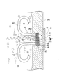
- FIG. 2 is a configuration diagram of the liquid level display device 40 in the first embodiment of the present invention.
- FIG. 3 is a perspective view showing a main part of the liquid level display device 40 in the first embodiment of the present invention.
- the liquid level display device 40 has a sight glass 41 provided on the wall portion 28 a of the oil tank 28.
- the wall portion 28a of the oil tank 28 is formed with a through hole 28a1 penetrating horizontally in the thickness direction.
- the sight glass 41 is attached to the outer wall side of the wall portion 28a with a screw (not shown), and closes the through hole 28a1.
- the sight glass 41 is provided with a predetermined liquid level range with a scale (not shown).
- the liquid level display device 40 has a liquid level quiet part 42.
- the liquid level quiet part 42 has a liquid introduction port 43 that communicates below the liquid level 100A in the oil tank 28 and a gas vent port 44 that communicates above the liquid level 100A.
- the liquid level quiet part 42 eliminates the influence of the liquid level 100A in the oil tank 28 and forms a quiet liquid level 100B for observation, thereby facilitating observation of the liquid level through the sight glass 41.
- the liquid level quiet part 42 of the present embodiment is formed by fitting the plug member 45 into the through hole 28a1.
- the plug member 45 has a disk-like flange portion 46 as shown in FIG.
- a plurality of seal fins 47 are provided on the outer periphery of the flange portion 46. As shown in FIG. 2, the seal fin 47 presses against the inner surface of the through hole 28a1, and seals the gap between the flange portion 46 and the through hole 28a1.
- a protrusion 49 having a screw 48 cut is provided at the center of the flange portion 46. By attaching a bolt or the like corresponding to the screw 48, the plug member 45 can be attached / removed easily.
- the flange portion 46 is provided with a liquid inlet 43 and a gas vent 44 arranged symmetrically with the protrusion 49 interposed therebetween.
- the liquid introduction port 43 is disposed vertically downward with respect to the protrusion 49, and is provided through the flange portion 46 horizontally in the thickness direction.
- the gas vent 44 is disposed vertically above the protrusion 49 and is provided through the flange 46 horizontally in the thickness direction.
- the liquid level display device 40 has a liquid introduction tube 50.
- the liquid introduction pipe 50 communicates with the liquid introduction port 43.
- One end of the liquid introduction tube 50 of the present embodiment is fitted into the liquid introduction port 43, and the one end fitted is caulked to be integrally attached to the plug member 45.
- the liquid introduction tube 50 includes an inclined portion 51, an extending portion 52, and a tip portion 53.
- the inclined portion 51 is a portion that extends substantially horizontally from the liquid inlet 43 toward the center of the oil tank 28.
- the inclined portion 51 is inclined downward by several degrees with respect to a horizontal plane (indicated by a dotted line in FIG. 2) extending from the liquid introduction port 43. Even if bubbles are introduced into the liquid introduction tube 50, the inclined portion 51 guides the bubbles to the liquid level quiet portion 42 by the buoyancy, so that the bubbles are clogged in the liquid introduction tube 50 and the liquid is introduced. Prevents the flow from being obstructed.
- the extending portion 52 is a portion that communicates with the inclined portion 51 and extends toward the bottom of the oil tank 28.
- the extending part 52 extends vertically downward from the lower end of the inclined part 51 by a predetermined distance.
- the extending portion 52 extends vertically downward to a depth at which the liquid flow due to the influence of the turbulence of the liquid surface 100A in the oil tank 28 in a short period is reduced.
- the extending part 52 forms a calm liquid level 100B in the liquid level calming part 42 by introducing the liquid toward the bottom of the oil tank 28 that is insensitive to the disturbance of the short period of the liquid level 100A.
- the front end portion 53 is a portion that communicates with the extending portion 52 and opens upward in the present embodiment, except for the downward direction below the liquid surface 100A.
- the tip 53 is open vertically upward below the liquid level 100A.
- the tip portion 53 opens upward under the liquid surface 100A, thereby preventing bubbles in the liquid from entering the inside of the tube.
- the distal end portion 53 is provided to be bent toward the inner wall side of the oil tank 28 with respect to the extending portion 52 from the lower end of the extending portion 52. As described above, the front end portion 53 is disposed on the side opposite to the center where foaming occurs in the oil tank 28.
- the turbo compressor 5 when the turbo compressor 5 is driven, the refrigerant gas X4 of the evaporator 4 is sucked by the impellers 13 and 14 and compressed to be compressed refrigerant gas X1 and led to the condenser 2. And this refrigerant
- coolant circulates through the condenser 2, the evaporator 4, and the turbo compressor 5 in order, and a refrigerating cycle is repeated.
- the turbo compressor 5 has a gear unit 25 for transmitting the rotational force of the electric motor 10 to the impellers 13 and 14. Below the gear unit 25, an oil tank 28 for storing lubricating oil supplied to the gear unit 25 is provided.
- the oil tank 28 is provided with a liquid level display device 40 for confirming at which timing oil leakage has occurred when the turbo compressor 5 is driven.
- This liquid level display device 40 communicates with the liquid inlet 43 and extends to the bottom of the oil tank 28 and extends to the bottom of the oil tank 28 and opens upwardly below the liquid level 100A.
- a liquid introduction pipe 50 having 53 is provided.
- the liquid introduction pipe 50 since it extends toward the bottom of the oil tank 28, a liquid that is less affected by the short-term periodic disturbance on the liquid level 100 ⁇ / b> A is introduced from the tip 53, and the liquid level calms down. It can be led to the part 42. For this reason, even if the liquid level 100A is violently disturbed in a short period, it is possible to prevent the range from being over in the observation through the sight glass 41. In addition, since there is a pressure loss due to piping in the liquid introduction pipe 50, the liquid level 100B seen from the sight glass 41 is insensitive to short-term periodic disturbances, and a time-average liquid level can be displayed.
- the tip 53 of the liquid introduction tube 50 opens upward under the liquid level 100A.
- the turbo compressor 5 is foamed in the oil tank 28 at the time of start-up, and bubbles that are relatively high in viscosity and difficult to break are generated. When this bubble enters the liquid introduction tube 50 and stays inside the tube, the flow of the liquid inside the tube is inhibited.
- the tip 53 of the liquid introduction tube 50 faces upward below the liquid surface 100A. By opening, it is possible to prevent bubbles in the liquid from entering the inside of the tube.
- the tip 53 of the liquid introduction pipe 50 is bent on the inner wall side of the oil tank 28. It is possible to more reliably prevent bubbles in the liquid from entering the inside of the tube.
- the liquid introduction tube 50 has an inclined portion 51 for guiding the bubbles introduced into the tube to the liquid level quiet portion 42 by its buoyancy. Therefore, even if air bubbles enter the inside of the liquid introduction pipe 50, it is possible to prevent the air bubbles from being clogged by inducing the air bubbles to the liquid level quiet portion 42 with an inclination.
- the above-described embodiment includes the liquid level quiet part 42 including the liquid inlet 43 communicating below the liquid level 100A in the oil tank 28 and the gas vent 44 communicating above the liquid level 100A, and the liquid level quiet part.
- the liquid level display apparatus 40 which has the sight glass 41 for observing the liquid level 100B in 42 is disclosed.
- the liquid level display device 40 communicates with the liquid introduction port 43 and extends toward the bottom of the oil tank 28, and communicates with the extended portion 52 and opens below the liquid level 100A except for the downward direction.
- the liquid introduction pipe 50 provided with the distal end portion 53, it is possible to accurately display the liquid level height of the oil tank 28 and observe oil leakage or the like of the oil tank 28.
- FIG. 4 is a configuration diagram of the liquid level display device 40 according to the second embodiment of the present invention. As shown in FIG. 4, the second embodiment differs from the above embodiment in that the liquid level display device 40 includes a gas vent pipe 60.
- the gas vent pipe 60 is integrally attached to the plug member 45 by fitting one end portion thereof into the gas vent port 44 and caulking the fitted one end portion.
- the gas vent pipe 60 includes an inclined portion 61, an extending portion (second extending portion) 62, and a tip portion (second tip portion) 63.
- the inclined portion 61 is a portion that extends substantially horizontally from the gas vent 44 toward the center of the oil tank 28.
- the inclined portion 61 is inclined upward by several degrees with respect to a horizontal plane (indicated by a dotted line in FIG. 4) extending from the gas vent 44.
- the extending part 62 is a part that communicates with the inclined part 61 and extends toward the top of the oil tank 28.
- the extending part 62 extends vertically upward from the upper end of the inclined part 61 by a predetermined distance.
- the distal end portion 63 is a portion that communicates with the extending portion 62 and opens upward in the liquid surface 100 ⁇ / b> A except for the upward direction, in this embodiment.
- the tip 63 is open vertically downward on the liquid level 100A. Further, the distal end portion 63 is provided to be bent from the upper end of the extending portion 62 toward the inner wall side of the oil tank 28 with respect to the extending portion 62.
- the gas vent pipe 60 since the gas vent pipe 60 extends toward the top of the oil tank 28, the gas vent pipe 60 can be vented even when the liquid level 100A in the oil tank 28 is largely disturbed.
- the liquid surface 100B to be observed can be kept calm by preventing introduction of the liquid from the mouth 44.
- tube 60 is opened downward on the liquid level 100A, even if it is a case where the liquid is pouring down from the upper direction, it can prevent that a liquid enters the inside of a pipe
- the second tip 63 of the gas vent pipe 60 is bent on the inner wall side of the oil tank 28.
- the gas vent pipe 60 has an inclined portion 61, and even if a liquid is introduced into the gas vent pipe 60, the liquid can be guided to the liquid level quiet portion 42 by its own weight. it can. Therefore, it is possible to prevent the gas vent pipe 60 from being clogged with liquid and hindering the gas flow.
- the second embodiment having the above-described configuration, even when the liquid level 100A is extremely turbulent in a short period, the liquid level of the oil tank 28 can be accurately displayed.
- the liquid introduction pipe is a pipe member that is not disposed inside, but the bubbles are cut (divided) into small portions so that the liquid introduction pipe is not clogged even if bubbles enter the inside.
- the cutter may be arranged in a cross shape at the tip.
- the form in which the tip portion of the liquid introduction tube opens upward is illustrated, but the present invention is not limited to this form, and the tip portion of the liquid introduction tube is inclined upward.
- the opening may be directed to the side.
- tip part of a degassing pipe opened directly downward was illustrated, this invention is not limited to this form,
- the 2nd degassing pipe is 2nd.
- the front end may be open obliquely downward or right side.
- the liquid level display device is applied to the oil tank.
- the present invention is not limited to this form, and can be applied to other liquid reservoirs.
- the present invention can be applied to a liquefied gas tank, and can be more suitably applied to a liquid circulation system tank in which liquid circulates and the total amount of liquid does not change much.
- the liquid level of the liquid reservoir can be accurately displayed.
Landscapes
- Engineering & Computer Science (AREA)
- Mechanical Engineering (AREA)
- General Engineering & Computer Science (AREA)
- Physics & Mathematics (AREA)
- Thermal Sciences (AREA)
- Fluid Mechanics (AREA)
- General Physics & Mathematics (AREA)
- Structures Of Non-Positive Displacement Pumps (AREA)
- Filling Or Discharging Of Gas Storage Vessels (AREA)
Description
本発明は、液面表示装置、ターボ圧縮機及びターボ冷凍機に関する。
本願は、2012年8月13日に日本国に出願された特願2012-179541号に基づき優先権を主張し、その内容をここに援用する。
本願は、2012年8月13日に日本国に出願された特願2012-179541号に基づき優先権を主張し、その内容をここに援用する。
冷凍機として、電動機によってインペラを回転させて冷媒を圧縮して排出するターボ圧縮機を備えるターボ冷凍機が知られている。ターボ圧縮機においては、油タンクから電動機の回転軸の軸受やインペラの回転軸の軸受等の摺動部位に潤滑油が供給される。このように潤滑油が供給される部位では、回転軸の周囲をシールするシール部から他の空間へ油漏れする可能性がある。
従来、この油漏れの発生を確認するために、油タンクに液面高さ観察用のサイトガラスを有する液面表示装置が設けられている。下記特許文献1には、液面高さ観察用の装置の一つとして差圧式液面計が記載されている。この差圧式液面計は、液化ガス用タンクに適した構成を有しており、高圧側の導圧管のうち開口端を含む先端部が、液化ガス用タンクの底部付近の内部に水平またはほぼ水平に差し入れられている。
ターボ圧縮機の油タンクは、液化ガス用タンクに比べて液体の貯溜量が少なく、上記差圧式液面計では、油漏れによる微小な液面の変化を観察することが困難である。例えば油タンクがギヤユニットの下方に配置され、ギヤユニットから液面に油が降り注ぐ場合には、液面が短時間周期で乱れるが、この液面の乱れが大きい場合には液面計がレンジオーバーとなって観察が困難となる。さらに、ターボ圧縮機の起動時等においては油タンク内が発泡するため、粘度が高く割れ難い気泡が導入管に入り込む場合があり、液面計において液面が正確に表示されない可能性がある。
本発明は、上記の事情に鑑みてなされたものであり、液体貯溜部の液面を正確に表示することができる液面表示装置、ターボ圧縮機及びターボ冷凍機の提供を目的とする。
本発明の第一の態様は、液体貯溜部における液面下に連通する液体導入口及び前記液面上に連通するガス抜き口を備える液面静穏部と、前記液面静穏部における液面を観察するためのサイトグラスと、を有する液面表示装置であって、前記液体導入口に連通し前記液体貯溜部の底部に向かって延在する延在部及び前記延在部に連通し前記液面下において下向きを除く向きに開口する先端部を備える液体導入管を有する。
本発明の第1の態様では、液面での短時間周期の乱れの影響が少なくなる液体貯溜部の底部に向かって液体導入管が延在しているため、サイトグラスを介した観察においてレンジオーバーになることを防止できる。また、配管による圧力損失により、サイトグラスから見える液面は短時間周期の乱れには鈍感になり、時間平均的な液面を表示することができる。また、液体導入管の先端部は、液面下において下向きを除く向きに開口しているため、液中の気泡が管内部に入り込むことを防止することができる。なお、ここで「下向き」とは真下及び斜め下向きを含み、「下向きを除く向き」とは、真横と、真上及び斜め上向きとを含む。
本発明の第1の態様では、液面での短時間周期の乱れの影響が少なくなる液体貯溜部の底部に向かって液体導入管が延在しているため、サイトグラスを介した観察においてレンジオーバーになることを防止できる。また、配管による圧力損失により、サイトグラスから見える液面は短時間周期の乱れには鈍感になり、時間平均的な液面を表示することができる。また、液体導入管の先端部は、液面下において下向きを除く向きに開口しているため、液中の気泡が管内部に入り込むことを防止することができる。なお、ここで「下向き」とは真下及び斜め下向きを含み、「下向きを除く向き」とは、真横と、真上及び斜め上向きとを含む。
本発明の第二の態様は、第一の態様において、前記液体導入管は、前記液面下において上向きに開口する前記先端部を備えても良い。
本発明の第二の態様では、液体導入管の先端部が、液面下において上向きに開口しているため、液中の気泡が管内部に入り込むことを確実に防止することができる。なお、ここで「上向き」とは、真上及び斜め上向きを含む。
本発明の第二の態様では、液体導入管の先端部が、液面下において上向きに開口しているため、液中の気泡が管内部に入り込むことを確実に防止することができる。なお、ここで「上向き」とは、真上及び斜め上向きを含む。
本発明の第三の態様は、第一、又は第二の態様において、前記液体導入管は、管内部に導入された気泡をその浮力により前記液面静穏部に導くための傾斜部を有しても良い。
本発明の第三の態様では、液体導入管の管内部に気泡が入り込んだとしても、傾斜を付けて液面静穏部に気泡を誘導することで、管内に気泡が詰まることを防止することができる。
本発明の第三の態様では、液体導入管の管内部に気泡が入り込んだとしても、傾斜を付けて液面静穏部に気泡を誘導することで、管内に気泡が詰まることを防止することができる。
本発明の第四の態様は、第一から第三のいずれかの態様において、前記先端部は、前記延在部に対して前記液体貯溜部の内壁側に向かって屈曲して設けられていても良い。
本発明の第四の態様では、気泡の発生は液体貯溜部の中央部よりも内壁側の方が少ないため、内壁側に液体導入管の先端部を屈曲させることで、液中の気泡が管内部に入り込むことを防止することができる。
本発明の第四の態様では、気泡の発生は液体貯溜部の中央部よりも内壁側の方が少ないため、内壁側に液体導入管の先端部を屈曲させることで、液中の気泡が管内部に入り込むことを防止することができる。
本発明の第五の態様は、第一から第四のいずれかの態様において、前記ガス抜き口に連通し前記液体貯溜部の頂部に向かって延在する第2の延在部及び前記第2の延在部に連通し前記液面上において上向きを除く向きに開口する第2の先端部を備えるガス抜き管を有しても良い。
本発明の第五の態様では、ガス抜き管が液体貯溜部の頂部に向かって延在しているため、液体貯溜部における液面の乱れが大きい場合であってもガス抜き口からの液体の導入を防止して、観察する液面を静穏に保つことができる。また、ガス抜き管の先端部は、液面上において上向きを除く向きに開口しているため、上方から液体が降り注いでいる場合であっても、液体が管内部に入り込むことを防止することができる。
なお、ここで「上向き」とは真上及び斜め上向きを含み、「上向きを除く向き」とは、真横と、真下及び斜め下向きとを含む。
本発明の第五の態様では、ガス抜き管が液体貯溜部の頂部に向かって延在しているため、液体貯溜部における液面の乱れが大きい場合であってもガス抜き口からの液体の導入を防止して、観察する液面を静穏に保つことができる。また、ガス抜き管の先端部は、液面上において上向きを除く向きに開口しているため、上方から液体が降り注いでいる場合であっても、液体が管内部に入り込むことを防止することができる。
なお、ここで「上向き」とは真上及び斜め上向きを含み、「上向きを除く向き」とは、真横と、真下及び斜め下向きとを含む。
本発明の第六の態様は、第五の態様において、前記ガス抜き管は、前記液面上において下向きに開口する前記第2の先端部を備えても良い。
本発明の第六の態様では、ガス抜き管の先端部が、液面上において下向きに開口しているため、上方から液体が降り注いでいる場合であっても、液体が管内部に入り込むことを確実に防止することができる。なお、ここで「下向き」とは、真下及び斜め下向きを含む。
本発明の第六の態様では、ガス抜き管の先端部が、液面上において下向きに開口しているため、上方から液体が降り注いでいる場合であっても、液体が管内部に入り込むことを確実に防止することができる。なお、ここで「下向き」とは、真下及び斜め下向きを含む。
本発明の第七の態様は、第五、又は第六の態様において、前記第2の先端部は、前記第2の延在部に対して前記液体貯溜部の内壁側に向かって屈曲して設けられていても良い。
本発明の第七の態様では、上方から降り注ぐ液体は液体貯溜部の中央部よりも内壁側の方が少ないため、内壁側にガス抜き管の第2の先端部を屈曲させることで、上方から降り注ぐ液体が管内部に入り込むことを防止することができる。
本発明の第七の態様では、上方から降り注ぐ液体は液体貯溜部の中央部よりも内壁側の方が少ないため、内壁側にガス抜き管の第2の先端部を屈曲させることで、上方から降り注ぐ液体が管内部に入り込むことを防止することができる。
本発明の第八の態様は、電動機によってインペラを回転させて気体を圧縮するターボ圧縮機であって、前記電動機の回転力を前記インペラに伝達するギヤユニットと、前記ギヤユニットの下方において前記ギヤユニットに供給される潤滑油を貯溜する油タンクと、を有し、前記油タンクの液面を表示する液面表示装置として、第一から第七のいずれかの態様の液面表示装置を有しても良い。
本発明の第九の態様は、圧縮された冷媒を液化する凝縮器と、前記凝縮器によって前記液化された冷媒を蒸発させて冷却対象物を冷却する蒸発器と、前記蒸発器によって前記蒸発された冷媒を圧縮して前記凝縮器に供給するターボ圧縮機と、を有するターボ冷凍機であって、前記ターボ圧縮機として、第八の態様のターボ圧縮機を有しても良い。
本発明によれば、液体貯溜部の液面を正確に表示することができる液面表示装置、ターボ圧縮機及びターボ冷凍機が得られる。
以下、本発明の実施形態について図面を参照して説明する。
(第1実施形態)
図1は、本発明の第1実施形態におけるターボ冷凍機1の系統図である。
本実施形態のターボ冷凍機1は、例えばフロンを冷媒として、空調用の冷水を冷却対象物とする。ターボ冷凍機1は、図1に示すように、凝縮器2と、エコノマイザ3と、蒸発器4と、ターボ圧縮機5と、を備えている。
図1は、本発明の第1実施形態におけるターボ冷凍機1の系統図である。
本実施形態のターボ冷凍機1は、例えばフロンを冷媒として、空調用の冷水を冷却対象物とする。ターボ冷凍機1は、図1に示すように、凝縮器2と、エコノマイザ3と、蒸発器4と、ターボ圧縮機5と、を備えている。
凝縮器2は、流路R1を介してターボ圧縮機5のガス吐出管5aと接続されている。凝縮器2には、ターボ圧縮機5によって圧縮された冷媒(圧縮冷媒ガスX1)が流路R1を通って供給される。凝縮器2は、この圧縮冷媒ガスX1を液化する。凝縮器2は、冷却水が流通する伝熱管2aを備え、圧縮冷媒ガスX1と冷却水との間の熱交換によって、圧縮冷媒ガスX1を冷却する。
圧縮冷媒ガスX1は、冷却水との間の熱交換によって冷却され、液化し、冷媒液X2となって凝縮器2の底部に溜まる。凝縮器2の底部は、流路R2を介してエコノマイザ3と接続されている。流路R2には、冷媒液X2を減圧するための膨張弁6が設けられている。エコノマイザ3には、膨張弁6によって減圧された冷媒液X2が流路R2を通って供給される。エコノマイザ3は、減圧された冷媒液X2を一時的に貯溜し、冷媒を液相と気相とに分離する。
エコノマイザ3の頂部は、流路R3を介してターボ圧縮機5のエコノマイザ連結管5bと接続されている。ターボ圧縮機5には、エコノマイザ3によって分離した冷媒の気相成分X3が、蒸発器4及び第1圧縮段11を経ることなく、流路R3を通って第2圧縮段12に供給され、効率を高める。一方、エコノマイザ3の底部は、流路R4を介して蒸発器4と接続されている。流路R4には、冷媒液X2をさらに減圧するための膨張弁7が設けられている。
蒸発器4には、膨張弁7によってさらに減圧された冷媒液X2が流路R4を通って供給される。蒸発器4は、冷媒液X2を蒸発させてその気化熱によって冷水を冷却する。蒸発器4は、冷水が流通する伝熱管4aを備え、冷媒液X2と冷水との間の熱交換によって、冷水を冷却すると共に冷媒液X2を蒸発させる。冷媒液X2は、冷水との間の熱交換によって熱を奪って蒸発し、冷媒ガスX4となる。
蒸発器4の頂部は、流路R5を介してターボ圧縮機5のガス吸入管5cと接続されている。ターボ圧縮機5には、蒸発器4において蒸発した冷媒ガスX4が流路R5を通って供給される。ターボ圧縮機5は、蒸発した冷媒ガスX4を圧縮し、圧縮冷媒ガスX1として凝縮器2に供給する。ターボ圧縮機5は、冷媒ガスX4を圧縮する第1圧縮段11と、一段階圧縮された冷媒をさらに圧縮する第2圧縮段12と、を備える2段圧縮機である。
第1圧縮段11にはインペラ13が設けられ、第2圧縮段12にはインペラ14が設けられており、それらが回転軸15で接続されている。ターボ圧縮機5は、電動機10によってインペラ13,14を回転させて冷媒を圧縮する。インペラ13,14は、ラジアルインペラであり、軸方向で吸気した冷媒を半径方向に排出する不図示の3次元的ねじれを含むブレードを有する。
ガス吸入管5cには、第1圧縮段11の吸入量を調節するためのインレットガイドベーン16が設けられている。インレットガイドベーン16は、冷媒ガスX4の流れ方向からの見かけ上の面積が変更可能なように回転可能とされている。インペラ13,14の周りには、それぞれディフューザ流路が設けられており、半径方向に排出した冷媒を、前記流路において圧縮・昇圧する。さらにインペラ13,14の周りに設けられたスクロール流路によって次の圧縮段に供給することができる。インペラ14の周りには、出口絞り弁17が設けられており、ガス吐出管5aからの吐出量を制御できる。
ターボ圧縮機5は、密閉型の筐体20を備える。筐体20は、圧縮流路空間S1と、第1の軸受収容空間S2と、モーター収容空間S3と、ギヤユニット収容空間S4と、第2の軸受収容空間S5と、に区画されている。圧縮流路空間S1には、インペラ13,14が設けられている。インペラ13,14を接続する回転軸15は、圧縮流路空間S1、第1の軸受収容空間S2、ギヤユニット収容空間S4に挿通して設けられている。第1の軸受収容空間S2には、回転軸15を支持する軸受21が設けられている。
モーター収容空間S3には、ステータ22と、ロータ23と、ロータ23に接続された回転軸24と、が設けられている。この回転軸24は、モーター収容空間S3、ギヤユニット収容空間S4、第2の軸受収容空間S5に挿通して設けられている。第2の軸受収容空間S5には、回転軸24の反負荷側を支持する軸受31が設けられている。ギヤユニット収容空間S4には、ギヤユニット25と、軸受26,27と、油タンク(液体貯溜部)28と、が設けられている。
ギヤユニット25は、回転軸24に固定される大径歯車29と、回転軸15に固定されると共に大径歯車29と噛み合う小径歯車30と、を有する。ギヤユニット25は、回転軸24の回転数に対して回転軸15の回転数が増加(増速)するように、回転力を伝達する。軸受26は、回転軸24を支持する。軸受27は、回転軸15を支持する。油タンク28は、ギヤユニット25の下方に設けられ、軸受21,26,27,31等の各摺動部位に供給される潤滑油を貯溜する。なお、符号37は、各摺動部位に潤滑油を供給する給油ポンプである。
このような筐体20には、圧縮流路空間S1と第1の軸受収容空間S2との間において、回転軸15の周囲をシールするシール部32,33が設けられている。また、筐体20には、圧縮流路空間S1とギヤユニット収容空間S4との間において、回転軸15の周囲をシールするシール部34が設けられている。また、筐体20には、ギヤユニット収容空間S4とモーター収容空間S3との間において、回転軸24の周囲をシールするシール部35が設けられている。また、筐体20には、モーター収容空間S3と第2の軸受収容空間S5との間において、回転軸24の周囲をシールするシール部36が設けられている。
ところで、ギヤユニット収容空間S4では、ギヤユニット25の特にインペラ13,14に回転力を伝達する大径歯車29によって、潤滑油が掻き上げられ、ミスト状の油滴や油煙が発生している。また、回転軸15,24の摺動部位におけるシールは完全ではないため、空間の圧力差等によって潤滑油が他の空間に漏れ出すと、油タンク28の液面が下がってしまう所謂油上がりが生じる場合がある。このため、油タンク28には、液面高さを観察するための液面表示装置40が設けられている。
以下、この液面表示装置40の構成について、図2及び図3を参照して説明する。
図2は、本発明の第1実施形態における液面表示装置40の構成図である。図3は、本発明の第1実施形態における液面表示装置40の主要部を示す斜視図である。
図2は、本発明の第1実施形態における液面表示装置40の構成図である。図3は、本発明の第1実施形態における液面表示装置40の主要部を示す斜視図である。
図2に示すように、液面表示装置40は、油タンク28の壁部28aに設けられたサイトグラス41を有する。油タンク28の壁部28aには、その厚み方向に水平に貫通する貫通口28a1が形成されている。サイトグラス41は、壁部28aの外壁側に不図示のネジによって取り付けられ、貫通口28a1を閉塞している。サイトグラス41には、不図示の目盛が付された所定の液面レンジが設けられている。
液面表示装置40は、液面静穏部42を有する。液面静穏部42は、油タンク28における液面100A下に連通する液体導入口43と、液面100A上に連通するガス抜き口44を有している。液面静穏部42は、油タンク28における液面100Aの影響を排除して観察用の静穏な液面100Bを形成することで、サイトグラス41を介した液面高さの観察をし易くする。本実施形態の液面静穏部42は、栓部材45を貫通口28a1に嵌め込むことで形成される。
栓部材45は、図3に示すように、円板状のフランジ部46を有する。フランジ部46の外周には、複数のシールフィン47が設けられている。シールフィン47は、図2に示すように、貫通口28a1の内面に押圧して、フランジ部46と貫通口28a1との隙間をシールする。フランジ部46の中央にはネジ48が切られた突部49が設けられている。このネジ48に対応するボルト等を螺合させることによって、栓部材45の取り付け/取り外しを容易に行うことができる。
フランジ部46には、突部49を挟んで対称配置された液体導入口43及びガス抜き口44が設けられている。液体導入口43は、突部49に対して鉛直下方に配置されており、フランジ部46を厚み方向に水平に貫通して設けられている。ガス抜き口44は、突部49に対して鉛直上方に配置されており、フランジ部46を厚み方向に水平に貫通して設けられている。
液面表示装置40は、液体導入管50を有する。液体導入管50は、液体導入口43に連通している。本実施形態の液体導入管50は、液体導入口43にその一端部が嵌め込まれ、その嵌め込んだ一端部をカシめることで、栓部材45に一体的に取り付けられている。この液体導入管50は、図2に示すように、傾斜部51と、延在部52と、先端部53と、を有している。
傾斜部51は、液体導入口43から油タンク28の中央に向かって略水平に延在する部分である。傾斜部51は、液体導入口43から延びる水平面(図2において点線で示す)に対し数度だけ下方に傾いている。この傾斜部51は、液体導入管50の内部に気泡が導入された場合であっても、気泡をその浮力によって液面静穏部42に導くことで、液体導入管50に気泡が詰まって液体の流動を阻害してしまうことを防止する。
延在部52は、傾斜部51に連通し、油タンク28の底部に向かって延在する部分である。延在部52は、傾斜部51の下端から鉛直下方に所定距離だけ延在している。延在部52は、油タンク28における液面100Aの短時間周期での乱れの影響による液体流動が少なくなる深さまで鉛直下方に延在している。この延在部52は、液面100Aの短時間周期の乱れには鈍感な油タンク28の底の方の液体を導入することで、液面静穏部42に静穏な液面100Bを形成する。
先端部53は、延在部52に連通し、液面100A下において下向きを除く向き、本実施形態では上向きに開口する部分である。この先端部53は、液面100A下において鉛直上方を向いて開口している。先端部53は、液面100A下において上向きに開口することで、液中の気泡が管内部に入り込むことを防止する。また、先端部53は、延在部52の下端から、延在部52に対して油タンク28の内壁側に向かって屈曲して設けられている。このように、先端部53は、油タンク28において発泡が生じる中央とは反対側に配置されている。
続いて、上記構成の液面表示装置40の作用について説明する。
図1に示すように、ターボ圧縮機5が駆動すると、蒸発器4の冷媒ガスX4がインペラ13,14によって吸い込まれ、圧縮されて圧縮冷媒ガスX1となって凝縮器2に導かれる。そして、この冷媒が、凝縮器2、蒸発器4、ターボ圧縮機5を順に循環することで、冷凍サイクルが繰り返される。ターボ圧縮機5は、電動機10の回転力をインペラ13,14に伝達するためのギヤユニット25を有する。ギヤユニット25の下方には、ギヤユニット25に供給される潤滑油を貯溜する油タンク28が設けられている。
ギヤユニット25は高温に発熱するため、大量の潤滑油が供給され、油タンク28には上方から潤滑油が降り注がれる。このため、油タンク28における液面100Aは、図2に示すように、短時間周期で激しく乱れる。この油タンク28には、ターボ圧縮機5の駆動時にどのタイミングで油漏れが発生したかを確認するための液面表示装置40が設けられている。この液面表示装置40は、液体導入口43に連通し油タンク28の底部に向かって延在する延在部52及び前記延在部52に連通し液面100A下において上向きに開口する先端部53を備える液体導入管50を有する。
この液体導入管50によれば、油タンク28の底部に向かって延在しているため、液面100Aでの短時間周期の乱れの影響が少ない液体を先端部53から導入し、液面静穏部42に導くことができる。このため、液面100Aが短時間周期で激しく乱れたとしても、サイトグラス41を介した観察においてレンジオーバーになることを防止できる。また、液体導入管50においては配管による圧力損失があるため、サイトグラス41から見える液面100Bは短時間周期の乱れには鈍感になり、時間平均的な液面を表示することができる。
また、この液体導入管50の先端部53は、液面100A下において上向きに開口している。ターボ圧縮機5は、起動時においては油タンク28内が発泡し、比較的粘度が高く割れ難い気泡が発生する。この気泡が、液体導入管50に入り込み、管内部に留まると、管内部における液体の流動を阻害するが、図2に示すように液体導入管50の先端部53が液面100A下において上向きに開口することによって、液中の気泡が管内部に入り込むことを防止することができる。
また、気泡の発生は油タンク28の中央部よりも油タンク28の内壁側の方が少ないため、本実施形態では油タンク28の内壁側に液体導入管50の先端部53を屈曲させることで、液中の気泡が管内部に入り込むことをより確実に防止することができる。
また、液体導入管50は、管内部に導入された気泡をその浮力により液面静穏部42に導くための傾斜部51を有している。そのため、万が一、液体導入管50の管内部に気泡が入り込んだとしても、傾斜を付けて液面静穏部42に気泡を誘導することで、管内に気泡が詰まることを防止することができる。
また、液体導入管50は、管内部に導入された気泡をその浮力により液面静穏部42に導くための傾斜部51を有している。そのため、万が一、液体導入管50の管内部に気泡が入り込んだとしても、傾斜を付けて液面静穏部42に気泡を誘導することで、管内に気泡が詰まることを防止することができる。
したがって、上述の本実施形態は、油タンク28における液面100A下に連通する液体導入口43及び前記液面100A上に連通するガス抜き口44を備える液面静穏部42と、液面静穏部42における液面100Bを観察するためのサイトグラス41と、を有する液面表示装置40を開示する。液面表示装置40は、液体導入口43に連通し油タンク28の底部に向かって延在する延在部52及び前記延在部52に連通し液面100A下において下向きを除く向きに開口する先端部53を備える液体導入管50を有することによって、油タンク28の液面高さを正確に表示して、油タンク28の油漏れ等を観察することができる。
(第2実施形態)
次に、本発明の第2実施形態について説明する。以下の説明において、第一実施形態と同一又は同等の構成を有する部分については同一の符号を付し、その説明を簡略若しくは省略する。
次に、本発明の第2実施形態について説明する。以下の説明において、第一実施形態と同一又は同等の構成を有する部分については同一の符号を付し、その説明を簡略若しくは省略する。
図4は、本発明の第2実施形態における液面表示装置40の構成図である。
図4に示すように、第2実施形態では、液面表示装置40がガス抜き管60を有する点で、上記実施形態と異なる。
図4に示すように、第2実施形態では、液面表示装置40がガス抜き管60を有する点で、上記実施形態と異なる。
ガス抜き管60は、ガス抜き口44にその一端部が嵌め込まれ、その嵌め込んだ一端部をカシめることで、栓部材45に一体的に取り付けられている。このガス抜き管60は、図4に示すように、傾斜部61と、延在部(第2の延在部)62と、先端部(第2の先端部)63と、を有している。傾斜部61は、ガス抜き口44から油タンク28の中央に向かって略水平に延在する部分である。傾斜部61は、ガス抜き口44から延びる水平面(図4において点線で示す)に対し数度だけ上方に傾いている。
延在部62は、傾斜部61に連通し、油タンク28の頂部に向かって延在する部分である。延在部62は、傾斜部61の上端から鉛直上方に所定距離だけ延在している。
先端部63は、延在部62に連通し、液面100A上において上向きを除く向き、本実施形態では下向きに開口する部分である。この先端部63は、液面100A上において鉛直下方を向いて開口している。また、先端部63は、延在部62の上端から、延在部62に対して油タンク28の内壁側に向かって屈曲して設けられている。
先端部63は、延在部62に連通し、液面100A上において上向きを除く向き、本実施形態では下向きに開口する部分である。この先端部63は、液面100A上において鉛直下方を向いて開口している。また、先端部63は、延在部62の上端から、延在部62に対して油タンク28の内壁側に向かって屈曲して設けられている。
上記構成の第2実施形態によれば、ガス抜き管60が、油タンク28の頂部に向かって延在しているため、油タンク28における液面100Aの乱れが大きい場合であってもガス抜き口44からの液体の導入を防止して、観察する液面100Bを静穏に保つことができる。また、ガス抜き管60の先端部63は、液面100A上において下向きに開口しているため、上方から液体が降り注いでいる場合であっても、液体が管内部に入り込むことを防止することができる。
また、上方からの液体の降り注ぎは油タンク28の中央部よりも油タンク28の内壁側の方が少ないため、油タンク28の内壁側にガス抜き管60の第2の先端部63を屈曲させることで、上方から降り注ぐ液体が管内部に入り込むことを防止することができる。また、ガス抜き管60は傾斜部61を有しており、万が一、ガス抜き管60の内部に液体が導入された場合であっても、液体をその自重によって液面静穏部42に導くことができる。そのため、ガス抜き管60に液体が詰まってガスの流動を阻害してしまうことを防止することができる。
このように、上記構成の第2実施形態によれば、液面100Aが短時間周期で非常に激しく乱れたとしても、正確に油タンク28の液面高さを表示することができる。
このように、上記構成の第2実施形態によれば、液面100Aが短時間周期で非常に激しく乱れたとしても、正確に油タンク28の液面高さを表示することができる。
以上、図面を参照しながら本発明の好適な実施形態について説明したが、本発明は上記実施形態に限定されるものではない。上述した実施形態において示した各構成部材の諸形状や組み合わせ等は一例であって、本発明の主旨から逸脱しない範囲において設計要求等に基づき種々変更可能である。
例えば、上記実施形態では、液体導入管は内部に何も配置されない管部材であるが、内部に気泡が入っても液体導入管を詰まらせないように、内部に気泡を小さく切断(分断)するためのカッターを、例えば先端部において十の字状に配置してもよい。
また、例えば、上記実施形態では、液体導入管の先端部が真上に向いて開口する形態を例示したが、本発明はこの形態に限定されることなく、液体導入管の先端部が斜め上や真横に向いて開口する形態であってもよい。
また、例えば、上記実施形態では、ガス抜き管の第2の先端部が真下に向いて開口する形態を例示したが、本発明はこの形態に限定されることなく、ガス抜き管の第2の先端部が斜め下や真横に向いて開口する形態であってもよい。
また、例えば、上記実施形態では、ガス抜き管の第2の先端部が真下に向いて開口する形態を例示したが、本発明はこの形態に限定されることなく、ガス抜き管の第2の先端部が斜め下や真横に向いて開口する形態であってもよい。
また、例えば、上記実施形態では、液面表示装置を油タンクに適用した形態を例示したが、本発明はこの形態に限定されることなく、他の液体貯溜部にも適用可能である。例えば、本発明は液化ガス用タンクにも適用でき、また、液体が循環し液量の総量があまり変化しない液体循環系のタンクにはより好適に適用することができる。
本発明の液面表示装置、及び、前記液面表示装置を備えるターボ圧縮機を備えるターボ冷凍機によれば、液体貯溜部の液面を正確に表示することができる。
1 ターボ冷凍機
2 凝縮器
4 蒸発器
5 ターボ圧縮機
10 電動機
13,14 インペラ
25 ギヤユニット
28 油タンク(液体貯溜部)
40 液面表示装置
41 サイトグラス
42 液面静穏部
43 液体導入口
44 ガス抜き口
50 液体導入管
51 傾斜部
52 延在部
53 先端部
60 ガス抜き管
62 延在部(第2の延在部)
63 先端部(第2の先端部)
100A 液面
100B 液面
2 凝縮器
4 蒸発器
5 ターボ圧縮機
10 電動機
13,14 インペラ
25 ギヤユニット
28 油タンク(液体貯溜部)
40 液面表示装置
41 サイトグラス
42 液面静穏部
43 液体導入口
44 ガス抜き口
50 液体導入管
51 傾斜部
52 延在部
53 先端部
60 ガス抜き管
62 延在部(第2の延在部)
63 先端部(第2の先端部)
100A 液面
100B 液面
Claims (9)
- 液体貯溜部における液面下に連通する液体導入口及び前記液面上に連通するガス抜き口を備える液面静穏部と、前記液面静穏部における液面を観察するためのサイトグラスと、を有する液面表示装置であって、
前記液体導入口に連通し前記液体貯溜部の底部に向かって延在する延在部及び前記延在部に連通し前記液面下において下向きを除く向きに開口する先端部を備える液体導入管を有する液面表示装置。 - 前記液体導入管は、前記液面下において上向きに開口する前記先端部を備える請求項1に記載の液面表示装置。
- 前記液体導入管は、管内部に導入された気泡をその浮力により前記液面静穏部に導くための傾斜部を有する請求項1または2に記載の液面表示装置。
- 前記先端部は、前記延在部に対して前記液体貯溜部の内壁側に向かって屈曲して設けられている請求項1~3のいずれか一項に記載の液面表示装置。
- 前記ガス抜き口に連通し前記液体貯溜部の頂部に向かって延在する第2の延在部及び前記第2の延在部に連通し前記液面上において上向きを除く向きに開口する第2の先端部を備えるガス抜き管を有する請求項1~4のいずれか一項に記載の液面表示装置。
- 前記ガス抜き管は、前記液面上において下向きに開口する前記第2の先端部を備える請求項5に記載の液面表示装置。
- 前記第2の先端部は、前記第2の延在部に対して前記液体貯溜部の内壁側に向かって屈曲して設けられている請求項5または6に記載の液面表示装置。
- 電動機によってインペラを回転させて気体を圧縮するターボ圧縮機であって、
前記電動機の回転力を前記インペラに伝達するギヤユニットと、
前記ギヤユニットの下方において前記ギヤユニットに供給される潤滑油を貯溜する油タンクと、を有し、
前記油タンクの液面を表示する液面表示装置として、請求項1~7のいずれか一項に記載の液面表示装置を備えるターボ圧縮機。 - 圧縮された冷媒を液化する凝縮器と、
前記凝縮器によって前記液化された冷媒を蒸発させて冷却対象物を冷却する蒸発器と、
前記蒸発器によって前記蒸発された冷媒を圧縮して前記凝縮器に供給するターボ圧縮機と、を有するターボ冷凍機であって、
前記ターボ圧縮機として、請求項8に記載のターボ圧縮機を備えるターボ冷凍機。
Priority Applications (2)
| Application Number | Priority Date | Filing Date | Title |
|---|---|---|---|
| CN201380039419.1A CN104508435B (zh) | 2012-08-13 | 2013-07-25 | 液面显示装置、涡轮压缩机以及涡轮冷冻机 |
| US14/599,720 US10030665B2 (en) | 2012-08-13 | 2015-01-19 | Liquid level indicator, turbo compressor, and turbo refrigerator |
Applications Claiming Priority (2)
| Application Number | Priority Date | Filing Date | Title |
|---|---|---|---|
| JP2012179541A JP5861592B2 (ja) | 2012-08-13 | 2012-08-13 | 液面表示装置、ターボ圧縮機及びターボ冷凍機 |
| JP2012-179541 | 2012-08-13 |
Related Child Applications (1)
| Application Number | Title | Priority Date | Filing Date |
|---|---|---|---|
| US14/599,720 Continuation US10030665B2 (en) | 2012-08-13 | 2015-01-19 | Liquid level indicator, turbo compressor, and turbo refrigerator |
Publications (1)
| Publication Number | Publication Date |
|---|---|
| WO2014027554A1 true WO2014027554A1 (ja) | 2014-02-20 |
Family
ID=50286257
Family Applications (1)
| Application Number | Title | Priority Date | Filing Date |
|---|---|---|---|
| PCT/JP2013/070184 Ceased WO2014027554A1 (ja) | 2012-08-13 | 2013-07-25 | 液面表示装置、ターボ圧縮機及びターボ冷凍機 |
Country Status (4)
| Country | Link |
|---|---|
| US (1) | US10030665B2 (ja) |
| JP (1) | JP5861592B2 (ja) |
| CN (1) | CN104508435B (ja) |
| WO (1) | WO2014027554A1 (ja) |
Families Citing this family (5)
| Publication number | Priority date | Publication date | Assignee | Title |
|---|---|---|---|---|
| JP6313090B2 (ja) * | 2014-03-28 | 2018-04-18 | 荏原冷熱システム株式会社 | ターボ冷凍機の蒸発器、および該蒸発器を備えたターボ冷凍機 |
| JP2019157708A (ja) * | 2018-03-09 | 2019-09-19 | 株式会社豊田自動織機 | 遠心圧縮機 |
| KR102027219B1 (ko) * | 2018-12-24 | 2019-10-01 | 주식회사 백콤 | 내부점검과 이물질 제거기능을 갖는 수봉식 진공펌프 |
| WO2020186096A1 (en) * | 2019-03-13 | 2020-09-17 | Johnson Controls Technology Company | Systems and methods for low-pressure refrigerant control |
| JP2023544331A (ja) * | 2020-09-30 | 2023-10-23 | ジョンソン・コントロールズ・タイコ・アイピー・ホールディングス・エルエルピー | バイパス導管を有するhvacシステム |
Citations (1)
| Publication number | Priority date | Publication date | Assignee | Title |
|---|---|---|---|---|
| JPH09126856A (ja) * | 1995-11-06 | 1997-05-16 | Miura Co Ltd | 液面計の取付構造 |
Family Cites Families (8)
| Publication number | Priority date | Publication date | Assignee | Title |
|---|---|---|---|---|
| JPS4833321Y1 (ja) * | 1970-10-31 | 1973-10-09 | ||
| JPS5654425U (ja) * | 1979-09-29 | 1981-05-13 | ||
| US5125541A (en) * | 1990-06-28 | 1992-06-30 | Dwight Angelhart | Viscous liquid dispensing apparatus |
| US5067327A (en) * | 1990-09-18 | 1991-11-26 | Enspeco Inc. | Refrigerant recovery and recharging device |
| JP3219519B2 (ja) * | 1993-02-12 | 2001-10-15 | 三洋電機株式会社 | 冷凍装置 |
| JP4863260B2 (ja) * | 2005-11-30 | 2012-01-25 | 東京エレクトロン株式会社 | 液面検出装置及びそれを備えた液処理装置 |
| CN201311312Y (zh) * | 2008-12-16 | 2009-09-16 | 上海宝钢设备检修有限公司 | 液位筒液位观察装置 |
| JP5356888B2 (ja) * | 2009-04-01 | 2013-12-04 | 川崎重工業株式会社 | 液化ガス用タンク |
-
2012
- 2012-08-13 JP JP2012179541A patent/JP5861592B2/ja not_active Expired - Fee Related
-
2013
- 2013-07-25 WO PCT/JP2013/070184 patent/WO2014027554A1/ja not_active Ceased
- 2013-07-25 CN CN201380039419.1A patent/CN104508435B/zh active Active
-
2015
- 2015-01-19 US US14/599,720 patent/US10030665B2/en active Active
Patent Citations (1)
| Publication number | Priority date | Publication date | Assignee | Title |
|---|---|---|---|---|
| JPH09126856A (ja) * | 1995-11-06 | 1997-05-16 | Miura Co Ltd | 液面計の取付構造 |
Also Published As
| Publication number | Publication date |
|---|---|
| JP5861592B2 (ja) | 2016-02-16 |
| CN104508435B (zh) | 2017-12-05 |
| CN104508435A (zh) | 2015-04-08 |
| JP2014038002A (ja) | 2014-02-27 |
| US10030665B2 (en) | 2018-07-24 |
| US20150128627A1 (en) | 2015-05-14 |
Similar Documents
| Publication | Publication Date | Title |
|---|---|---|
| CN101504004B (zh) | 涡轮压缩机和制冷机 | |
| JP6056270B2 (ja) | ターボ圧縮機及びターボ冷凍機 | |
| JP5861592B2 (ja) | 液面表示装置、ターボ圧縮機及びターボ冷凍機 | |
| CN101504002B (zh) | 涡轮压缩机以及制冷机 | |
| JP2011001937A (ja) | スクリュ圧縮機 | |
| JPWO2010137274A1 (ja) | 冷凍サイクル装置 | |
| CN102213232B (zh) | 驱动轴构造、涡轮压缩机及涡轮制冷机 | |
| JP6799792B2 (ja) | 流体機械及び冷凍サイクル装置 | |
| US20180252233A1 (en) | Turbo compressor and turbo chilling apparatus equipped with the turbo compressor | |
| JP2015021418A (ja) | ターボ圧縮機及びターボ冷凍機 | |
| JP5983188B2 (ja) | ターボ圧縮機及びターボ冷凍機 | |
| JP6064489B2 (ja) | ターボ冷凍機 | |
| CN108779946B (zh) | 制冷机 | |
| JP5334801B2 (ja) | 2段スクリュ圧縮機および冷凍装置 | |
| US8833102B2 (en) | Turbo compressor and refrigerator | |
| US20200080756A1 (en) | Refrigeration machine | |
| JP5545326B2 (ja) | ターボ圧縮機及び冷凍機 | |
| JP2018123759A (ja) | ターボ圧縮機 | |
| CN102207094A (zh) | 涡轮压缩机以及涡轮冷冻机 | |
| JP6079486B2 (ja) | 液位計測装置、ターボ圧縮機及びターボ冷凍機 | |
| JP6044156B2 (ja) | 油切り構造、ターボ圧縮機及びターボ冷凍機 | |
| JP2010019148A (ja) | タービン発電機 | |
| KR20160043405A (ko) | 압축기의 리어 헤드 |
Legal Events
| Date | Code | Title | Description |
|---|---|---|---|
| 121 | Ep: the epo has been informed by wipo that ep was designated in this application |
Ref document number: 13879258 Country of ref document: EP Kind code of ref document: A1 |
|
| NENP | Non-entry into the national phase |
Ref country code: DE |
|
| 122 | Ep: pct application non-entry in european phase |
Ref document number: 13879258 Country of ref document: EP Kind code of ref document: A1 |