WO2014024759A1 - 表示装置 - Google Patents
表示装置 Download PDFInfo
- Publication number
- WO2014024759A1 WO2014024759A1 PCT/JP2013/070835 JP2013070835W WO2014024759A1 WO 2014024759 A1 WO2014024759 A1 WO 2014024759A1 JP 2013070835 W JP2013070835 W JP 2013070835W WO 2014024759 A1 WO2014024759 A1 WO 2014024759A1
- Authority
- WO
- WIPO (PCT)
- Prior art keywords
- sealing material
- display surface
- seal
- display device
- display
- Prior art date
- Legal status (The legal status is an assumption and is not a legal conclusion. Google has not performed a legal analysis and makes no representation as to the accuracy of the status listed.)
- Ceased
Links
Images







Classifications
-
- G—PHYSICS
- G06—COMPUTING OR CALCULATING; COUNTING
- G06F—ELECTRIC DIGITAL DATA PROCESSING
- G06F1/00—Details not covered by groups G06F3/00 - G06F13/00 and G06F21/00
- G06F1/16—Constructional details or arrangements
- G06F1/1601—Constructional details related to the housing of computer displays, e.g. of CRT monitors, of flat displays
-
- G—PHYSICS
- G06—COMPUTING OR CALCULATING; COUNTING
- G06F—ELECTRIC DIGITAL DATA PROCESSING
- G06F3/00—Input arrangements for transferring data to be processed into a form capable of being handled by the computer; Output arrangements for transferring data from processing unit to output unit, e.g. interface arrangements
- G06F3/01—Input arrangements or combined input and output arrangements for interaction between user and computer
- G06F3/03—Arrangements for converting the position or the displacement of a member into a coded form
- G06F3/041—Digitisers, e.g. for touch screens or touch pads, characterised by the transducing means
-
- H—ELECTRICITY
- H05—ELECTRIC TECHNIQUES NOT OTHERWISE PROVIDED FOR
- H05K—PRINTED CIRCUITS; CASINGS OR CONSTRUCTIONAL DETAILS OF ELECTRIC APPARATUS; MANUFACTURE OF ASSEMBLAGES OF ELECTRICAL COMPONENTS
- H05K5/00—Casings, cabinets or drawers for electric apparatus
- H05K5/06—Hermetically-sealed casings
- H05K5/063—Hermetically-sealed casings sealed by a labyrinth structure provided at the joining parts
-
- G—PHYSICS
- G02—OPTICS
- G02F—OPTICAL DEVICES OR ARRANGEMENTS FOR THE CONTROL OF LIGHT BY MODIFICATION OF THE OPTICAL PROPERTIES OF THE MEDIA OF THE ELEMENTS INVOLVED THEREIN; NON-LINEAR OPTICS; FREQUENCY-CHANGING OF LIGHT; OPTICAL LOGIC ELEMENTS; OPTICAL ANALOGUE/DIGITAL CONVERTERS
- G02F1/00—Devices or arrangements for the control of the intensity, colour, phase, polarisation or direction of light arriving from an independent light source, e.g. switching, gating or modulating; Non-linear optics
- G02F1/01—Devices or arrangements for the control of the intensity, colour, phase, polarisation or direction of light arriving from an independent light source, e.g. switching, gating or modulating; Non-linear optics for the control of the intensity, phase, polarisation or colour
- G02F1/13—Devices or arrangements for the control of the intensity, colour, phase, polarisation or direction of light arriving from an independent light source, e.g. switching, gating or modulating; Non-linear optics for the control of the intensity, phase, polarisation or colour based on liquid crystals, e.g. single liquid crystal display cells
- G02F1/133—Constructional arrangements; Operation of liquid crystal cells; Circuit arrangements
- G02F1/1333—Constructional arrangements; Manufacturing methods
- G02F1/133308—Support structures for LCD panels, e.g. frames or bezels
-
- G—PHYSICS
- G02—OPTICS
- G02F—OPTICAL DEVICES OR ARRANGEMENTS FOR THE CONTROL OF LIGHT BY MODIFICATION OF THE OPTICAL PROPERTIES OF THE MEDIA OF THE ELEMENTS INVOLVED THEREIN; NON-LINEAR OPTICS; FREQUENCY-CHANGING OF LIGHT; OPTICAL LOGIC ELEMENTS; OPTICAL ANALOGUE/DIGITAL CONVERTERS
- G02F1/00—Devices or arrangements for the control of the intensity, colour, phase, polarisation or direction of light arriving from an independent light source, e.g. switching, gating or modulating; Non-linear optics
- G02F1/01—Devices or arrangements for the control of the intensity, colour, phase, polarisation or direction of light arriving from an independent light source, e.g. switching, gating or modulating; Non-linear optics for the control of the intensity, phase, polarisation or colour
- G02F1/13—Devices or arrangements for the control of the intensity, colour, phase, polarisation or direction of light arriving from an independent light source, e.g. switching, gating or modulating; Non-linear optics for the control of the intensity, phase, polarisation or colour based on liquid crystals, e.g. single liquid crystal display cells
- G02F1/133—Constructional arrangements; Operation of liquid crystal cells; Circuit arrangements
- G02F1/1333—Constructional arrangements; Manufacturing methods
- G02F1/133308—Support structures for LCD panels, e.g. frames or bezels
- G02F1/133311—Environmental protection, e.g. against dust or humidity
-
- G—PHYSICS
- G02—OPTICS
- G02F—OPTICAL DEVICES OR ARRANGEMENTS FOR THE CONTROL OF LIGHT BY MODIFICATION OF THE OPTICAL PROPERTIES OF THE MEDIA OF THE ELEMENTS INVOLVED THEREIN; NON-LINEAR OPTICS; FREQUENCY-CHANGING OF LIGHT; OPTICAL LOGIC ELEMENTS; OPTICAL ANALOGUE/DIGITAL CONVERTERS
- G02F1/00—Devices or arrangements for the control of the intensity, colour, phase, polarisation or direction of light arriving from an independent light source, e.g. switching, gating or modulating; Non-linear optics
- G02F1/01—Devices or arrangements for the control of the intensity, colour, phase, polarisation or direction of light arriving from an independent light source, e.g. switching, gating or modulating; Non-linear optics for the control of the intensity, phase, polarisation or colour
- G02F1/13—Devices or arrangements for the control of the intensity, colour, phase, polarisation or direction of light arriving from an independent light source, e.g. switching, gating or modulating; Non-linear optics for the control of the intensity, phase, polarisation or colour based on liquid crystals, e.g. single liquid crystal display cells
- G02F1/133—Constructional arrangements; Operation of liquid crystal cells; Circuit arrangements
- G02F1/1333—Constructional arrangements; Manufacturing methods
- G02F1/133308—Support structures for LCD panels, e.g. frames or bezels
- G02F1/133331—Cover glasses
-
- G—PHYSICS
- G02—OPTICS
- G02F—OPTICAL DEVICES OR ARRANGEMENTS FOR THE CONTROL OF LIGHT BY MODIFICATION OF THE OPTICAL PROPERTIES OF THE MEDIA OF THE ELEMENTS INVOLVED THEREIN; NON-LINEAR OPTICS; FREQUENCY-CHANGING OF LIGHT; OPTICAL LOGIC ELEMENTS; OPTICAL ANALOGUE/DIGITAL CONVERTERS
- G02F1/00—Devices or arrangements for the control of the intensity, colour, phase, polarisation or direction of light arriving from an independent light source, e.g. switching, gating or modulating; Non-linear optics
- G02F1/01—Devices or arrangements for the control of the intensity, colour, phase, polarisation or direction of light arriving from an independent light source, e.g. switching, gating or modulating; Non-linear optics for the control of the intensity, phase, polarisation or colour
- G02F1/13—Devices or arrangements for the control of the intensity, colour, phase, polarisation or direction of light arriving from an independent light source, e.g. switching, gating or modulating; Non-linear optics for the control of the intensity, phase, polarisation or colour based on liquid crystals, e.g. single liquid crystal display cells
- G02F1/133—Constructional arrangements; Operation of liquid crystal cells; Circuit arrangements
- G02F1/1333—Constructional arrangements; Manufacturing methods
- G02F1/13338—Input devices, e.g. touch panels
-
- G—PHYSICS
- G02—OPTICS
- G02F—OPTICAL DEVICES OR ARRANGEMENTS FOR THE CONTROL OF LIGHT BY MODIFICATION OF THE OPTICAL PROPERTIES OF THE MEDIA OF THE ELEMENTS INVOLVED THEREIN; NON-LINEAR OPTICS; FREQUENCY-CHANGING OF LIGHT; OPTICAL LOGIC ELEMENTS; OPTICAL ANALOGUE/DIGITAL CONVERTERS
- G02F2201/00—Constructional arrangements not provided for in groups G02F1/00 - G02F7/00
- G02F2201/36—Airflow channels, e.g. constructional arrangements facilitating the flow of air
-
- G—PHYSICS
- G06—COMPUTING OR CALCULATING; COUNTING
- G06F—ELECTRIC DIGITAL DATA PROCESSING
- G06F2203/00—Indexing scheme relating to G06F3/00 - G06F3/048
- G06F2203/041—Indexing scheme relating to G06F3/041 - G06F3/045
- G06F2203/04103—Manufacturing, i.e. details related to manufacturing processes specially suited for touch sensitive devices
-
- Y—GENERAL TAGGING OF NEW TECHNOLOGICAL DEVELOPMENTS; GENERAL TAGGING OF CROSS-SECTIONAL TECHNOLOGIES SPANNING OVER SEVERAL SECTIONS OF THE IPC; TECHNICAL SUBJECTS COVERED BY FORMER USPC CROSS-REFERENCE ART COLLECTIONS [XRACs] AND DIGESTS
- Y10—TECHNICAL SUBJECTS COVERED BY FORMER USPC
- Y10T—TECHNICAL SUBJECTS COVERED BY FORMER US CLASSIFICATION
- Y10T428/00—Stock material or miscellaneous articles
- Y10T428/24—Structurally defined web or sheet [e.g., overall dimension, etc.]
- Y10T428/24777—Edge feature
Definitions
- the present invention relates to a display device including a protective plate, a touch panel, and the like.
- a display device in which a protective plate using a transparent member or the like is installed on the display surface side of the display unit in order to protect the display surface of the display unit from impact or dirt.
- a touch panel is installed on the display surface side of the display unit.
- a protective plate and a touch panel are adhered and fixed to the display surface side of the display unit by a sealing material disposed around the display surface of the display unit.
- FIG. 14 is a diagram showing a schematic configuration of the display unit 91, the sealing material 92, and the protection plate 93 in the conventional display device 900.
- FIG. 15 is a plan view showing the positional relationship between the display unit 91 and the sealing material 92 of the display device 900.
- the sealing material 92 is disposed so as to surround the display surface 911 of the display unit 91, and the inside surrounded by the sealing material 92.
- the vents 941 and 942 are arranged so that the region and the external region are partially connected.
- the seal material 92 is arranged in this way, and the display unit 91 and the protective plate 93 are bonded and fixed, thereby preventing condensation and preventing foreign matters from being mixed in from the outside. That is, by arranging the sealing material 92 as described above, ventilation is ensured by the vents 941 and 942, so that water vapor hardly remains in the space between the display surface 911 and the protective plate 93, and the temperature rapidly increases. Even when the temperature rises, condensation is unlikely to occur between the display portion 91 and the protective plate 93. Further, by arranging the sealing material 92 as described above, the paths connecting the inner side and the outer side of the space between the display surface 911 surrounded by the sealing material 92 and the protective plate 93 are vent holes 941 and 942. Therefore, foreign matter can be prevented from entering the space between the display surface 911 and the protective plate 93 from the outside.
- the vents 941 and 942 are linear paths in a plan view, and the width of the vent (or outlet) (or the vent inlet (or outlet)). Foreign matter such as dust or dust may enter the space between the display unit 91 and the protective plate 93 from the outside.
- the present invention prevents condensation in the space between the protective plate, the touch panel, and the like and the display surface of the display unit, and the space between the protective plate, the touch panel, etc., and the display surface of the display unit.
- An object of the present invention is to realize a display device that effectively prevents foreign matter from entering from the outside.
- the display device having the first configuration includes a display unit, a protection unit, and a sealing material.
- the display unit has a display surface for displaying data.
- the protection unit is disposed so as to cover the display surface.
- the sealing material is provided between the display unit and the protection unit, and is provided so as to surround the display surface in a plan view viewed from above the display surface, and the inner region surrounded by the sealing material and the sealing material It is provided so as to form a path connecting the outer region with a shape other than a straight line.
- this display device it is possible to secure ventilation between the space between the protection unit and the display unit and the space outside the sealing material, thereby preventing condensation in the space between the protection unit and the display unit. can do. Further, in this display device, the inner region and the outer region surrounded by the sealing material are connected by a non-straight path by the sealing material, so that the space between the display unit and the protection unit is formed. It is possible to effectively prevent foreign matters from entering from the outside.
- the “protection unit” may be a touch panel (for example, a capacitive touch panel).
- the display surface in the first configuration, has a rectangular shape, and the sealing material is outside each of the four sides of the display surface in a plan view as viewed from above the display surface.
- the 1st sealing material, the 2nd sealing material, the 3rd sealing material, and the 4th sealing material which are arranged are included. Further, in a plan view as viewed from above the display surface, between the first seal material and the second seal material, between the second seal material and the third seal material, and between the third seal material and the fourth seal material.
- the inner region surrounded by the first seal material, the second seal material, the third seal material, and the fourth seal material and the outer A path is formed to connect the region in a shape that is bent twice at a right angle.
- the inner area and the outer area surrounded by the sealing material are more complicated paths, i.e., the inner area and the outer area surrounded by the sealing material are perpendicular to each other in plan view. Since the connection is made through a path that bends twice, it is possible to prevent condensation in the space between the protective portion and the display portion, and foreign matter enters the space between the display portion and the protective portion from the outside. This can be more effectively prevented.
- right angle is a concept that includes a substantially right angle, and is a concept that allows design errors and the like.
- the display device of the third configuration is the first configuration, wherein the display surface is rectangular, and the sealing material is on the outside of each of the four sides of the display surface in a plan view as viewed from above the display surface.
- the 1st sealing material, the 2nd sealing material, the 3rd sealing material, and the 4th sealing material which are arranged are included. Further, in a plan view as viewed from above the display surface, between the first seal material and the second seal material, between the second seal material and the third seal material, and between the third seal material and the fourth seal material.
- the inner region surrounded by the first seal material, the second seal material, the third seal material, and the fourth seal material and the outer A path is formed to connect the region with an acute angle and an odd number of turns.
- the inner region and the outer region surrounded by the sealing material have more complicated paths, that is, the inner region and the outer region surrounded by the sealing material at an acute angle in plan view. Since it is connected by a path having an odd number of turns, it is possible to prevent condensation in the space between the protection unit and the display unit, and foreign matter enters the space between the display unit and the protection unit from the outside. This can be more effectively prevented.
- the display device is the display device according to the first configuration, in which the display surface is rectangular, and the sealing material is outside each of the four sides of the display surface in a plan view as viewed from above the display surface.
- the 1st sealing material, the 2nd sealing material, the 3rd sealing material, and the 4th sealing material which are arranged are included.
- the first end of the first sealing material is disposed in the vicinity of the second end of the second sealing material.
- the first end of the second sealing material is disposed in the vicinity of the second end of the third sealing material.
- the first end of the third sealing material is disposed in the vicinity of the second end of the fourth sealing material.
- the first end of the fourth sealing material is disposed in the vicinity of the second end of the first sealing material.
- the first sealing material has a substantially trapezoidal notch in the end region of the first end, and the second sealing material is in a region facing the notch of the first sealing material. , Having a triangular cutout.
- the second sealing material has a substantially trapezoidal notch in the end region of the first end, and the third sealing material is in a region facing the notch of the second sealing material. , Having a triangular cutout.
- the third sealing material has a substantially trapezoidal notch in the end region of the first end, and the fourth sealing material is in a region facing the notch of the third sealing material. , Having a triangular cutout.
- the fourth sealing material has a substantially trapezoidal notch in the end region of the first end, and the first sealing material is in a region facing the notch of the fourth sealing material. , Having a triangular cutout.
- a display device of a fifth configuration is the first configuration, wherein the sealing material is provided so as to surround the display surface in a plan view viewed from above the display surface, and an inner region surrounded by the sealing material. It is provided so as to form a path connecting the outer region of the sealing material with a substantially arc shape.
- the sealing material in the first configuration, is provided so as to surround the display surface in a plan view as viewed from above the display surface, and an inner region surrounded by the sealing material It is provided so as to form a path connecting the outer region of the sealing material in a substantially S shape.
- the display surface in the first configuration, is rectangular, and the sealing material is on the outside of each of the four sides of the display surface in a plan view viewed from above the display surface.
- the 1st sealing material, the 2nd sealing material, the 3rd sealing material, and the 4th sealing material which are arranged are included.
- the first end of the first sealing material is disposed in the vicinity of the second end of the second sealing material.
- the first end of the second sealing material is disposed in the vicinity of the second end of the third sealing material.
- the first end of the third sealing material is disposed in the vicinity of the second end of the fourth sealing material.
- the first end of the fourth sealing material is disposed in the vicinity of the second end of the first sealing material.
- the first sealing material has a substantially rectangular cutout in the end region of the first end, and the second sealing material is in a region facing the cutout of the first sealing material. , Having a substantially semi-elliptical cutout.
- the second seal material has a substantially rectangular cutout portion in the end region of the first end, and the third seal material is in a region facing the cutout portion of the second seal material. , Having a substantially semi-elliptical cutout.
- the third sealing material has a substantially rectangular cutout in the end region of the first end, and the fourth sealing material is in a region facing the cutout of the third sealing material. , Having a substantially semi-elliptical cutout.
- the fourth seal material has a substantially rectangular cutout in the end region of the first end, and the first seal material is in a region facing the cutout of the fourth seal material. , Having a substantially semi-elliptical cutout.
- the display surface has a rectangular shape
- the sealing material has four sides of the display surface as viewed from above the display surface.
- a first seal material, a second seal material, a third seal material, and a fourth seal material are disposed outside each side. Further, in a plan view as viewed from above the display surface, between the first seal material and the second seal material, between the second seal material and the third seal material, and between the third seal material and the fourth seal material. And between at least one between the fourth seal material and the first seal material, the inner region surrounded by the first seal material, the second seal material, the third seal material, and the fourth seal material and the outer A path connecting the regions is formed.
- the first position is a position where the path is connected to the inner region surrounded by the first seal material, the second seal material, the third seal material, and the fourth seal material.
- the width is the first width
- the width at the second position which is the position where the path is connected to the outer region surrounded by the first seal material, the second seal material, the third seal material, and the fourth seal material, is the first width.
- the width is 2
- the path connecting the inner area and the outer area surrounded by the first seal material, the second seal material, the third seal material, and the fourth seal material is a plan view as viewed from above the display surface. In at least a portion between the first position and the second position, the width is larger than the larger one of the first width and the second width.
- this display device in a plan view, an area where foreign substances are likely to stay can be provided in the middle of the path connecting the inner area and the outer area surrounded by the sealing material. Therefore, in this display device, it is possible to prevent dew condensation in the space between the protection unit and the display unit, and in the middle part of the path connecting the inner region and the outer region surrounded by the sealing material. The foreign matter that enters from the outside can be retained, and the foreign matter can be effectively prevented from entering the space between the display portion and the protection portion.
- dew condensation is prevented in the space between the protective plate, the touch panel, etc. and the display surface of the display unit, and foreign matter is externally introduced into the space between the protective plate, the touch panel, etc., and the display surface of the display unit.
- a display device that effectively prevents intrusion can be realized.
- FIG. 1 is a schematic configuration diagram of a display device 1000 according to a first embodiment.
- the top view which shows schematic structure of the display apparatus 1000 which concerns on 1st Embodiment.
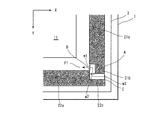
- region AR1 of the top view which shows schematic structure of the display apparatus 1000 which concerns on 1st Embodiment.
- the top view which shows schematic structure of the display apparatus which concerns on 2nd Embodiment.
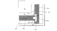
- region AR2 of the top view which shows schematic structure of the display apparatus which concerns on 2nd Embodiment.
- region of the top view which shows schematic structure of the display apparatus which concerns on the 1st modification of 2nd Embodiment.
- region of the top view which shows schematic structure of the display apparatus which concerns on the 2nd modification of 2nd Embodiment.
- region of the top view which shows schematic structure of the display apparatus which concerns on the 3rd modification of 2nd Embodiment.
- region of the top view which shows schematic structure of the display apparatus which concerns on the 4th modification of 2nd Embodiment.
- region of the top view which shows schematic structure of the display apparatus which concerns on the 5th modification of 2nd Embodiment.
- 1 is a schematic configuration diagram of a conventional display device.
- FIG. 1 is a schematic diagram showing a schematic configuration of a display device 1000 according to the first embodiment.
- FIG. 2 is a plan view (plan view seen from above the display surface 11 of the display device 1000) showing a schematic configuration of the display device 1000.
- FIG. 1 is a schematic diagram showing a schematic configuration of a display device 1000 according to the first embodiment.
- FIG. 2 is a plan view (plan view seen from above the display surface 11 of the display device 1000) showing a schematic configuration of the display device 1000.
- FIG. 1 is a schematic diagram showing a schematic configuration of a display device 1000 according to the first embodiment.
- FIG. 2 is a plan view (plan view seen from above the display surface 11 of the display device 1000) showing a schematic configuration of the display device 1000.
- FIG. 1 is a schematic diagram showing a schematic configuration of a display device 1000 according to the first embodiment.
- FIG. 2 is a plan view (plan view seen from above the display surface 11 of the display device 1000) showing a schematic configuration of the display device 1000.
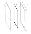
- the display device 1000 is a sealing material installed between the display unit 1 and the protection plate 3 in order to bond and fix the display unit 1 including the display surface 11 for displaying data and the display unit 1 and the protection plate 3. 2 and a protective plate 3 arranged to cover the display surface of the display unit 1 in order to protect the display surface 11 of the display unit 1.
- the display unit 1 is formed by fitting and fixing a liquid crystal panel, an organic EL panel, or the like to the display unit frame 12. As shown in FIG. 1, the liquid crystal panel, the organic EL panel, etc. are fitted into the display unit frame 12 so that the display surface 11 such as a liquid crystal panel, an organic EL panel, etc. is arranged in the opening portion of the display frame 12. Secure with.
- the sealing material 2 is installed between the display unit 1 and the protective plate 3 in order to bond and fix the display unit 1 and the protective plate 3.
- the sealing material 2 includes a first sealing material 21, a second sealing material 22, a third sealing material 23, and a fourth sealing material 24. As shown in FIGS. 1 and 2, the first sealing material 21, the second sealing material 22, the third sealing material 23, and the fourth sealing material 24 surround the display surface 11 of the display unit 1. Be placed.
- a double-sided tape or an adhesive substance (adhesive urethane, rubber, sponge, etc.) is used as the 1st sealing material 21, the 2nd sealing material 22, the 3rd sealing material 23, and the 4th sealing material 24, for example, a double-sided tape or an adhesive substance (adhesive urethane, rubber, sponge, etc.) is used. Used.
- the first sealing material 21 is formed of an elongated rectangular portion 21a, a first extending portion 21b, and a second extending portion 21c.
- the first extending portion 21b has a width shorter than the width of the rectangular portion 21a, and one side thereof coincides with the first side in the longitudinal direction of the rectangular portion 21a from the first end in the longitudinal direction of the rectangular portion 21a.
- the second extending portion 21c has a width shorter than the width of the rectangular portion 21a, and one side thereof coincides with the first side in the longitudinal direction of the rectangular portion 21a from the second end in the longitudinal direction of the rectangular portion 21a.
- the second sealing material 22 is formed of an elongated rectangular portion 22a, a first extending portion 22b, and a second extending portion 22c.
- the first extending portion 22b has a width shorter than the width of the rectangular portion 22a, and one side thereof coincides with the first side in the longitudinal direction of the rectangular portion 22a from the first end in the longitudinal direction of the rectangular portion 22a.
- the second extending portion 22c has a width shorter than the width of the rectangular portion 22a, and one side thereof coincides with the first side in the longitudinal direction of the rectangular portion 22a from the second end in the longitudinal direction of the rectangular portion 22a.
- the third sealing material 23 is formed of an elongated rectangular portion 23 a, a first extending portion 23 b, and a second extending portion 23 c, and the first sealing material 21.
- the second extending portion 23c of the third sealing material 23 has the same shape as the extending portion 21b, and the second extending portion 23c of the third sealing material 23 has the same shape as the second extending portion 21c of the first sealing material 21.
- the fourth sealing material 24 is formed of an elongated rectangular rectangular portion 24 a, a first extending portion 24 b, and a second extending portion 24 c, and the second sealing material 22.
- the second extending portion 24 c of the fourth sealing material 24 has the same shape as the second extending portion 22 c of the second sealing material 22.
- FIG. 3 is an enlarged view of the area AR1 in FIG.
- the X axis and the Y axis are set, the right direction is the X axis positive direction, and the lower direction is the Y axis positive direction.
- the end point on the display surface 11 side of the first extending portion of the first seal material 21 is designated as point A
- the end point on the display surface 11 side of the second seal material 22 is designated as point B
- the second seal An end point on the first sealing material 21 side of the second extending portion 22c of the material 22 is defined as a C point.
- the X coordinate of point A is X (A)
- the Y coordinate of end point A is Y (A)
- the X coordinate of point B is X (B)
- the Y coordinate of end point B is Y (B)
- the X coordinate of the C point is X (C)
- the Y coordinate of the end point C is Y (C).
- the first seal material 21 is such that the Y coordinate position (Y (A)) of the end portion of the first extending portion 21 b on the second seal material 22 side is a rectangular portion of the second seal material 22. It arrange
- the second seal material 22 has an X coordinate position (X (C)) of an end portion of the second extending portion 22 c on the first seal material 21 side of the first seal material 21. It arrange
- the path P1 changes in direction at two places (the direction of the center line of the path is 90 at two places.
- a vent having a variable path P1) can be formed. That is, as described above, by arranging the first sealing material 21 and the second sealing material 22, the area inside the sealing material 2 (on the display surface 11 side) and the area outside the sealing material 2 are connected.
- the vent path P1 can be formed such that the direction of the center line changes at two locations.
- the mouth (upper left vent in FIG. 2) and the vent formed between the fourth seal member 24 and the first seal member 21 (upper right vent in FIG. 2) are also described above. This is the same as the vent formed by the first seal member 21 and the second seal member 22 (the lower right portion vent in FIG. 2).
- the first sealing material is arranged so that the second extending portion 21 c is disposed on the upper side and the first extending portion 21 b is disposed on the lower side of the display surface 11. 21 is arranged.
- the second sealing material 22 is arranged in the lower outer region of the display surface 11 such that the first extending portion 22 b is disposed on the left side and the second extending portion 22 c is disposed on the right side. Place.
- the third sealing material is arranged so that the first extending portion 23 b is disposed on the upper side and the second extending portion 23 c is disposed on the lower side region of the display surface 11. 23 is arranged.
- the fourth sealing material 24 is arranged so that the first extending portion 24 b is disposed on the right side and the second extending portion 24 c is disposed on the left side in the upper and outer regions of the display surface 11. Place.
- the first seal is set so that the width of the vent hole (the value of Y (C) -Y (A) or the value of X (A) -X (B) in FIG. 3) is in the range of 0 to 1 mm. It is preferable to arrange the material 21, the second sealing material 22, the third sealing material 23, and the fourth sealing material 24. For example, it is preferable to arrange the first sealing material 21 and the second sealing material 22 so that the width w1 in FIG. 3 is 0.5 mm, the width w2 is 0.5 mm, and the width w3 is 0.5 mm.
- the protective plate 3 is disposed so as to cover the display surface of the display unit 1 in order to protect the display surface 11 of the display unit 1.
- the protection plate 3 is formed of, for example, a plate-like transparent member in order to protect the display surface 11 of the display unit 1 from an impact, dust, or the like.
- the protective plate 3 may be a touch panel (for example, a capacitive touch panel).
- the first sealing material 21, the second sealing material 22, the third sealing material 23, and the fourth sealing material 24 each having a rectangular portion, a first extending portion, and a second extending portion. Between the first sealing material 21, the second sealing material 22, the third sealing material 23, and the fourth sealing material 24, and a shape that is not linear in a plan view. It arrange
- the inner region (the region on the display surface 11 side) surrounded by the sealing material 2 and the outer region can be connected by a vent hole that is not linear in a plan view. Condensation in the space between the protective plate 3 and the display surface 11 of the display unit 1 can be prevented.
- the display device 1000 has a vent hole that connects the inner area (the area on the display surface 11 side) and the outer area with the sealing material 2 and has a non-linear path in plan view. It is effective that foreign matters such as dust or dust smaller than the width (or the area of the inlet (or outlet) of the vent) enter the space between the display unit 1 and the protective plate 3 from the outside. Can be prevented.
- the shape of the sealing material is different from that in the first embodiment.
- the rest is the same as in the first embodiment.
- the same parts as those in the above embodiment are denoted by the same reference numerals, and detailed description thereof is omitted.
- the seal material of the present embodiment includes a first seal material 221, a second seal material 222, a third seal material 223, and a fourth seal material 224.
- the first sealing material 221 includes an elongated rectangular portion 221a, a first extending portion 221b extending in the longitudinal direction from the rectangular portion 221a, and a rectangular portion 221a of the first extending portion 221b.
- a second extending portion 221c extending from the opposite end to the rectangular portion 221a and having the same width as the rectangular portion 221a is formed.
- the first extending portion 221b has a width shorter than the width of the rectangular portion 221a, and one side thereof coincides with the first side in the longitudinal direction of the rectangular portion 221a from the first end in the longitudinal direction of the rectangular portion 221a.
- the rectangular portion 221a is formed to extend in the longitudinal direction.
- the second sealing material 222 includes an elongated rectangular portion 222a, a first extending portion 222b extending in the longitudinal direction from the rectangular portion 222a, and a rectangular portion 222a of the first extending portion 222b. It is formed from a second extending portion 222c that extends in the longitudinal direction of the rectangular portion 222a with substantially the same width as the rectangular portion 222a from the opposite end.
- the first extending portion 222b has a width shorter than the width of the rectangular portion 222a, and one side thereof coincides with the first side in the longitudinal direction of the rectangular portion 222a from the first end in the longitudinal direction of the rectangular portion 222a. Are formed to extend in the longitudinal direction of the rectangular portion 222a.
- the third seal material 223 is formed of an elongated rectangular portion 223 a, a first extension portion 223 b, and a second extension portion 223 c, and the first seal material 221 is formed.
- the extension portion 221b has the same shape, and the second extension portion 223c of the third seal member 223 has the same shape as the second extension portion 221c of the first seal member 221.
- the fourth sealing material 224 is formed of a long and narrow rectangular portion 224 a, a first extending portion 224 b, and a second extending portion 224 c, and the second sealing material 222.
- the second extending portion 224c of the fourth sealing material 224 has the same shape as the second extending portion 222c of the second sealing material 222.
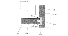
- FIG. 5 is an enlarged view of the area AR2 in FIG.
- the X axis and the Y axis are set, the right direction is the X axis positive direction, and the lower direction is the Y axis positive direction.
- the end point on the display surface 11 side and the rectangular portion 221 a side of the first extending portion 221 b of the first sealing material 221 is defined as D point
- An end point on the extended portion 221c side is set as an E point.
- the end point on the display surface 11 side and the first seal material 221 side of the second seal material 222 is F point, the opposite side of the display surface 11 of the second seal material 222 and the first seal material.
- the end point on the 221 side be the G point.
- the X coordinate of the end point ⁇ is expressed as X ( ⁇ )
- the Y coordinate of the end point ⁇ is expressed as Y ( ⁇ ).
- the first sealing material 221 and the second sealing material 222 have the Y coordinate (Y (D)) of the end point D smaller than the Y coordinate (Y (F)) of the end point F, and
- the end point E is arranged such that the Y coordinate (Y (E)) of the end point E is larger than the Y coordinate (Y (G)) of the end point G.
- the first sealing material 221 and the second sealing material 222 have the X coordinate (X (D)) of the end point D larger than the X coordinate (X (F)) of the end point F, And it arrange
- first sealing material 221 and the second sealing material 222 are arranged so as to satisfy the conditions according to the following four inequalities.
- the path P2 changes in direction at two places (the direction of the center line of the path is 90 at two places.
- a vent having a variable path P2) can be formed. That is, as described above, by arranging the first sealing material 221 and the second sealing material 222, the area inside the sealing material 2 (on the display surface 11 side) and the area outside the sealing material 2 are connected.
- the vent path P2 can be formed such that the direction of the center line changes at two locations.
- a vent formed between the second seal member 222 and the third seal member 223 (a vent in the lower left part of FIG. 4), and a vent formed between the third seal member 223 and the fourth seal member 224.
- the opening (the upper left vent in FIG. 4) and the vent formed between the fourth sealing member 224 and the first sealing member 221 (the upper right vent in FIG. 4) are also described above. This is the same as the vent formed by the first seal member 221 and the second seal member 222 (the lower right portion vent in FIG. 4).
- the first sealing material 221 is arranged in the right outer region of the display surface 11 so that the first extending part 221 b and the second extending part 221 c are arranged on the lower side.
- the second sealing material 222 is arranged in the lower outer region of the display surface 11 so that the first extending part 222 b and the second extending part 222 c are arranged on the left side.
- the third sealing material 223 is arranged in the left outer region of the display surface 11 so that the first extending part 223 b and the second extending part 223 c are arranged on the upper side.
- the fourth sealing material 224 is arranged in the upper and outer regions of the display surface 11 so that the first extending portion 224 b and the second extending portion 224 c are arranged on the right side.
- the first sealing material 21, the second sealing material 22, the third sealing material 23, and the fourth sealing material 24 are arranged so that the width of the vent hole is in the range of 0 to 1 mm.
- the first sealing material 21 and the second sealing material 22 are arranged so that the width w4 in FIG. 5 is 0.5 mm, the width w5 is 0.5 mm, and the width w6 is 0.5 mm.
- the first seal member 221, the second seal member 222, the third seal member 223, and the fourth member having the rectangular portion, the first extending portion, and the second extending portion.
- the sealing material 224 is disposed so as to surround the display surface 11, and is linear between the first sealing material 221, the second sealing material 222, the third sealing material 223, and the fourth sealing material 224 in plan view. It arrange
- the inner region (the region on the display surface 11 side) surrounded by the sealing material 2 and the outer region can be connected by a vent hole in a path that is not linear in plan view.
- the sealing material 2 has a vent hole that connects the inner region (the region on the display surface 11 side) and the outer region and has a non-linear path in plan view.
- a foreign matter such as dust or dust smaller than the width of the entrance (or exit) of the mouth (or the area of the entrance (or exit) of the vent) enters the space between the display unit 1 and the protective plate 3 from the outside. It can be effectively prevented.
- the display device of this modification is the display device of the second embodiment, in which the first sealing material 221 is the first sealing material 321, the second sealing material 222 is the second sealing material 322, and the third sealing material 223 is the second sealing material.
- the third sealing material 323 is replaced with the fourth sealing material 224 with the fourth sealing material 324, respectively.
- the display device of this modification is the same as the display device of the second embodiment.
- FIG. 6 is an enlarged view of the lower right portion of the plan view of the display device of the present modification viewed from above the display surface 11 of the display unit 1 as in FIG. It is a figure which expands and shows the edge part vicinity of the 2nd sealing material.
- the second sealant 322 of the display device of the present modification is disposed at the end of the rectangular portion 222a of the second sealant 222 of the display device of the second embodiment on the first sealant 221 side. It has a shape provided with a notch 322d.
- the three end surfaces forming the notch 322d are paste end surfaces formed of an adhesive material.
- the first sealing material 321, the third sealing material 323, and the fourth sealing material 324 of the display device of this modification also have a shape provided with the same notch portion as the second sealing material 322 described above. .
- the shape of the path in plan view of the vent formed between each of the second sealing material 322, the third sealing material 323, the fourth sealing material 324, and the first sealing material 321 is shown in FIG. It becomes the same as the shape.
- the first sealing material 321 of the display device of the present modification has the same shape as the notch 322d at the end of the rectangular portion 221a of the first sealing material 221 of the display device of the second embodiment on the fourth sealing material 224 side. It has a shape with a notch.
- the third sealant 323 of the display device of the present modification has the same shape as the notch 322d at the end of the rectangular portion 223a of the third sealant 223 of the display device of the second embodiment on the second sealant 222 side. It has a shape with a notch.
- the fourth sealant 324 of the display device of the present modification has the same shape as the notch 322d at the end of the rectangular portion 224a of the fourth sealant 224 of the display device of the second embodiment on the third sealant 223 side. It has a shape with a notch.
- the first sealing material 21, the second sealing material 22, the third sealing material 23, and the fourth sealing material 24 are in the range of 0 to 1 mm.
- the first sealing material 21 and the second sealing material 22 are arranged so that the width w7 in FIG. 6 is 0.5 mm, the width w8 is 0.5 mm, and the width w11 is 0.5 mm.
- the width W9 of FIG. 6 is just to set the width W9 of FIG. 6 to 1 mm and the width w10 to 1 mm as a shape of the notch part 322d for retaining a foreign material, for example.
- the display device of the present modification has directions at two locations as shown in FIG. 6 as in the display device of the second embodiment.
- a vent having a changing path P3 can be formed, and foreign substances entering from the outside can easily stay on the glue end surface of the notch 322d (the region inside the notch 322d). Therefore, in the display device according to the present modification, a vent hole having a path that is not linear in a plan view is secured, and condensation in the space between the protection plate 3 and the display surface 11 of the display unit 1 is prevented.
- By providing a region where foreign matter stays in the middle of the path it is possible to effectively prevent the foreign matter from entering the space between the display unit 1 and the protection plate 3 from the outside.
- the display device of this modification is the display device of the second embodiment, in which the first sealing material 221 is the first sealing material 421, the second sealing material 222 is the second sealing material 422, and the third sealing material 223 is the second sealing material.
- the third sealing material 423 is replaced with the fourth sealing material 224 with the fourth sealing material 424, respectively.
- the display device of this modification is the same as the display device of the second embodiment.
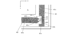
- FIG. 7 is an enlarged view of the lower right portion of the plan view of the display device of the present modification viewed from above the display surface 11 of the display unit 1 as in FIG. It is a figure which expands and shows the edge part vicinity of the 2nd sealing material 422.
- FIG. 7 is an enlarged view of the lower right portion of the plan view of the display device of the present modification viewed from above the display surface 11 of the display unit 1 as in FIG. It is a figure which expands and shows the edge part vicinity of the 2nd sealing material 422.
- the second sealant 422 of the display device of the present modification includes a rectangular portion 422a, a first extending portion 422b extending from the rectangular portion 422a in the longitudinal direction of the rectangular portion 422a, and a rectangular portion 422a from the first extending portion 422b.
- the second extending portion 422c extending in the longitudinal direction and the first protruding portion 422d and the second protruding portion 422e extending to the opposite side of the first extending portion 421b of the rectangular portion 422a are formed.
- the 1st extension part 421b and the 2nd extension part 421c are respectively the same shapes as the 1st extension part 222b and the 2nd extension part 222c of 2nd Embodiment.
- the first projecting portion 422 d extends from the region that occupies approximately half of the upper side (display surface 11 side) of the end portion of the rectangular portion 422 a on the first sealing material 421 side in the longitudinal direction of the rectangular portion 422 a.
- the first seal member 421 has a shape extending in a triangular shape. Note that the two end surfaces of the first projecting portion 422d on the first sealing material 421 side are glue end surfaces formed of an adhesive substance.
- the second projecting portion 422 e extends from a region that occupies approximately half of the lower side (opposite to the display surface 11) of the end portion of the rectangular portion 422 a on the first sealing material 421 side. It has a shape extending in a triangular shape toward the first sealing material 421 in the longitudinal direction. Note that the two end surfaces of the second projecting portion 422e on the first sealing material 421 side are paste end surfaces formed of an adhesive substance.
- the second sealing material 422 having the above-described shape has a triangular notch 422f at the end on the first sealing material 421 side. Therefore, the triangular notch Foreign matter from outside tends to stay in the region 422f.
- the width w12 in FIG. 7 may be 0.5 mm and the width w13 may be 1 mm.
- the shape of the end portion of the material 424 on the third sealing material 323 side is also the same shape as the shape formed from the first protruding portion 422d and the second protruding portion 422e of the second sealing material 422 described above.
- the shape of the path in plan view of the vent formed between each of the second seal material 422, the third seal material 423, the fourth seal material 424, and the first seal material 421 is shown in FIG. It becomes the same as the shape.
- the first sealing member 421 of the display device of the present modification has the shape of the end portion on the fourth sealing member 224 side of the rectangular portion 221a of the first sealing member 221 of the display device of the second embodiment as the first protrusion 422d. And it is set as the shape similar to the shape formed from the 2nd projection part 422e.
- the third sealant 423 of the display device according to the present modification is configured so that the end portion of the rectangular portion 223a of the third sealant 223 of the display device according to the second embodiment on the second sealant 222 side is the first protrusion 422d. And it is set as the shape similar to the shape formed from the 2nd projection part 422e.
- the fourth sealant 424 of the display device according to the present modification has the shape of the end of the rectangular portion 223a of the third sealant 223 of the display device according to the second embodiment on the second sealant 222 side, and the first protrusion 422d. And it is set as the shape similar to the shape formed from the 2nd projection part 422e.
- the display device of the present modification has directions at two locations as shown in FIG. 7 as in the display device of the second embodiment.
- a vent having a changing path P4 can be formed, and foreign substances entering from the outside can easily stay on the glue end surface of the triangular notch 422f (the region inside the notch 422f). Therefore, in the display device according to the present modification, a vent hole having a path that is not linear in a plan view is secured, and condensation in the space between the protection plate 3 and the display surface 11 of the display unit 1 is prevented.
- the region where the foreign matter stays in the middle of the path it is possible to effectively prevent the foreign matter from entering the space between the display unit 1 and the protection plate 3 from the outside.
- the display device of this modification is the same as the display device of the second modification, in which the first sealing material 421 is the first sealing material 521, the second sealing material 422 is the second sealing material 522, and the third sealing material 423 is the second sealing material 423.
- the third sealing material 523 is replaced with the fourth sealing material 424 by the fourth sealing material 524, respectively.
- the display device of the present modification is the same as the display device of the second modification of the second embodiment.
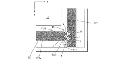
- FIG. 8 is an enlarged view of the lower right portion of the plan view of the display device of the present modification viewed from above the display surface 11 of the display unit 1, similar to FIG. 5, and the first sealant 521 of the present modification and It is a figure which expands and shows the edge part vicinity of the 2nd sealing material 522.
- FIG. 8 is an enlarged view of the lower right portion of the plan view of the display device of the present modification viewed from above the display surface 11 of the display unit 1, similar to FIG. 5, and the first sealant 521 of the present modification and It is a figure which expands and shows the edge part vicinity of the 2nd sealing material 522.
- the shape of the end of the second sealant 522 of the display device of the present modification on the first sealant 521 side is the same shape as the second sealant 422 of the display device of the second modification. That is, the first protrusion 522d of the second seal member 522 of the present modification has the same shape as the first protrusion 422d of the second seal member 422 of the second modification, and the second seal member 522 of the present modification.
- the second protrusion 522e has the same shape as the second protrusion 422e of the second sealant 422 of the second modification.
- the first sealant 521 of the display device of the present modification has a substantially same shape as the first protrusion 522d at the same Y coordinate position as the first protrusion 522d on the surface disposed on the display surface 11 side.
- the second protrusion 522e has the same Y coordinate position as the second protrusion 522e and has a shape that is cut out. That is, as shown in FIG. 8, the Y coordinate (Y (K)) of the K point, which is the tip of the first protrusion 522d of the second sealant 522, and the notch on the upper side (inside) of the first sealant 521.
- the Y coordinate (Y (M)) of the M point that is the tip of the second protrusion 522e of the second sealant 522 is substantially the same as the Y coordinate (Y (H)) of the H point that is the tip of the part.
- the Y coordinate (Y (J)) of point J, which is the tip of the lower (outside) notch portion of the first sealant 521, is substantially the same.
- Ventilation holes By arranging the first sealing material 521 and the second sealing material 522 having such a shape as shown in FIG. 8, a complicated path is formed between the first sealing material 521 and the second sealing material 522. Ventilation holes (ventilation holes having paths bent at acute angles at three locations) can be formed.
- the width w14 in FIG. 8 may be 1 mm.
- the shape of the end of the second sealant 522 on the third sealant 523 side, the shape of the end of the third sealant 523 on the fourth sealant 524 side, and the fourth seal of the display device of this modification example is also the same shape as the shape of the end portion on the second sealing material 522 side of the first sealing material 521 described above.
- the shape of the path in plan view of the vent formed between each of the second sealing material 522, the third sealing material 523, the fourth sealing material 524, and the first sealing material 521 is shown in FIG. It becomes the same as the shape.
- a vent having a path P ⁇ b> 5 whose direction changes at three acute angles. can be formed. Therefore, in the display device according to the present modification, a vent hole in a path that is not linear in a plan view is secured, condensation in the space between the protective plate 3 and the display surface 11 of the display unit 1 is prevented, and more complicated.
- the vent having the path can effectively prevent foreign matter from entering the space between the display unit 1 and the protection plate 3 from the outside.
- the display device of this modification is the same as the display device of the third modification, in which the first sealing material 521 is the first sealing material 621, the second sealing material 522 is the second sealing material 622, and the third sealing material 523 is the second sealing material.
- the third sealing material 623 is replaced with the fourth sealing material 524 with the fourth sealing material 624, respectively.
- the display device of the present modification is the same as the display device of the third modification of the second embodiment.
- FIG. 9 is an enlarged view of the lower right portion of the plan view of the display device of the present modification viewed from above the display surface 11 of the display unit 1 as in FIG. It is a figure which expands and shows the edge part vicinity of the 2nd sealing material 622.
- FIG. 9 is an enlarged view of the lower right portion of the plan view of the display device of the present modification viewed from above the display surface 11 of the display unit 1 as in FIG. It is a figure which expands and shows the edge part vicinity of the 2nd sealing material 622.
- the shape of the end of the second sealant 622 of the display device of the present modification on the first sealant 621 side is the same as that of the second sealant 422 of the display device of the second modification. That is, the first protrusion 622d of the second seal member 622 of this modification has the same shape as the first protrusion 422d of the second seal member 422 of the second modification, and the second seal member 622 of this modification.
- the second protrusion 622e has the same shape as the second protrusion 422e of the second sealant 422 of the second modification.
- the first sealing material 621 of the display device has a shape in which a substantially trapezoidal shape is cut out on the surface arranged on the display surface 11 side, as shown in FIG. That is, as shown in FIG. 9, the Y coordinate (Y (P)) of point P, which is the tip of the first protrusion 622 d of the second sealant 622, and the upper side of the bottom surface of the notch of the first sealant 621
- the Y coordinate (Y (N)) of the N point that is the (inner side) end point is substantially the same, and the Y coordinate (Y (R) of the R point that is the tip of the second protrusion 622e of the second sealant 622.
- the Y coordinate (Y (O)) of point O which is the lower (outer) end point of the bottom surface of the cutout portion of the first sealing material 621, are substantially the same.
- the three end surfaces of the cutout portion of the first sealing material 621 are paste end surfaces formed of an adhesive material.
- the width w15 in FIG. 9 may be 1 mm and the width w16 may be 1 mm.
- the shape of the end of the second sealant 622 on the third sealant 623 side, the shape of the end of the third sealant 623 on the fourth sealant 624 side, and the fourth seal of the display device of this modification example is also the same shape as the shape of the end portion on the second sealing material 622 side of the first sealing material 621 described above.
- the shape of the path in plan view of the vent formed between each of the second seal material 622, the third seal material 623, the fourth seal material 624, and the first seal material 621 is shown in FIG. It becomes the same as the shape.
- first sealing material 621 and the second sealing material 622 having the shapes as described above as shown in FIG. 9, a plan view is provided between the first sealing material 621 and the second sealing material 622.
- a non-linear path vent can be formed, and foreign substances entering from the outside can be easily retained on the glue end surface of the cutout portion of the first seal material 621.
- a vent hole having a path that is not linear in a plan view is secured, and condensation in the space between the protection plate 3 and the display surface 11 of the display unit 1 is prevented.
- the display device of the present modification is the display device of the second embodiment, in which the first sealing material 221 is the first sealing material 721, the second sealing material 222 is the second sealing material 722, and the third sealing material 223 is the second sealing material.
- the third sealing material 723 is replaced with the fourth sealing material 224 with the fourth sealing material 724, respectively.
- the display device of this modification is the same as the display device of the second embodiment.
- FIG. 10 is an enlarged view of the lower right portion of the plan view of the display device of the present modification viewed from above the display surface 11 of the display unit 1, as in FIG. It is a figure which expands and shows the edge part vicinity of the 2nd sealing material 722.
- FIG. 10 is an enlarged view of the lower right portion of the plan view of the display device of the present modification viewed from above the display surface 11 of the display unit 1, as in FIG. It is a figure which expands and shows the edge part vicinity of the 2nd sealing material 722.
- the shape of the end of the first sealant 721 on the second sealant 722 side has a shape obtained by cutting out a substantially semicircular cutout 721d from a rectangle as shown in FIG.
- the shape of the end of the second sealing material 722 on the first sealing material 721 side is a shape having a substantially semicircular extending portion 722f extending in the longitudinal direction from an elongated rectangle as shown in FIG.
- the shape of the end portion of the second sealing material 722 on the third sealing material 723 side is the same as the shape of the end portion of the first sealing material 721 shown in FIG.
- the notch part of 722 of the 2nd sealing material is formed inside (upper side (display surface 11 side)).
- the end of the first sealant 721 on the fourth sealant 724 side (upper side) (the end opposite to the end shown in FIG. 10) is the second end of the second sealant 722 shown in FIG.
- the shape is the same as the shape of the end portion on the one sealing material side.
- the width w17 in FIG. 7 may be 0.5 mm.
- the shape of the end of the third sealant 723 on the fourth sealant 724 side of the third sealant 723 and the shape of the end of the fourth sealant 724 on the first sealant 721 side of the display device of this modification are the first sealant. This is the same as the shape of the end portion of 721 on the second sealing material 722 side.
- the shape of the end of the third sealant 723 on the second sealant 722 side of the third sealant 723 and the shape of the end of the fourth sealant 724 on the side of the third sealant 723 are the second sealant.
- the shape of the end portion on the first sealing material 721 side of 722 is the same. Thereby, the shape of the path in plan view of the vent formed between each of the second seal material 722, the third seal material 723, the fourth seal material 724, and the first seal material 721 is shown in FIG. It becomes the same as the shape.
- the first sealing material 721 and the second sealing material 722 having the shapes as described above are arranged between the first sealing material 721 and the second sealing material 722 in plan view.
- a non-linear path (arc-shaped path) can be formed.
- a similar vent can be formed between the third sealing material 723, the fourth sealing material 724, and the first sealing material 721.
- a vent hole that is not linear in a plan view (arc-shaped route) is secured, and condensation in the space between the protection plate 3 and the display surface 11 of the display unit 1 is prevented.
- a region where foreign matter stays in the middle of the route of the vent hole it is possible to effectively prevent the foreign matter from entering the space between the display unit 1 and the protection plate 3 from the outside.
- variety of the 1st sealing material of the sealing material 2, the 2nd sealing material, the 3rd sealing material, and the 4th sealing material was substantially equal was demonstrated, it is not limited to this, 1st
- the widths of the sealing material, the second sealing material, the third sealing material, and the fourth sealing material may be different.
- the first sealing material, the second sealing material, the third sealing material, and the fourth sealing material may have different widths in plan view. FIG.
- the display device 1000 includes, for example, a display unit 1 that is formed by being fitted into a frame (bezel) 12 that fixes a liquid crystal unit (or organic EL unit) 13, and a protective plate 3 (or touch panel).
- the first sealant 821, the second sealant 822, the third sealant 823, and the fourth sealant 824 are disposed between the display unit 1 and the protective plate 3 so as to surround the display surface 11.
- FIG. 11 shows a case where the first seal material 821, the second seal material 822, the third seal material 823, and the fourth seal material 824 have different widths, and the first seal material 821, the second seal material 822, and the third seal material.
- the inner region and the outer region surrounded by the sealing material in plan view according to the respective widths of the first sealing material 821, the second sealing material 822, the third sealing material 823, and the fourth sealing material 824 is determined so that the same area as that of the first embodiment forms a vent hole. That's fine.
- the embodiments and modifications other than the first embodiment may be applied when the widths of the first sealing material, the second sealing material, the third sealing material, and the fourth sealing material of the sealing material 2 are different. Good. Also in this case, as in the case shown in FIG. 11, the first sealing material, the second sealing material, the third sealing material, and the fourth sealing material are formed so as to form the same vent holes as those shown in the embodiment and the modification. What is necessary is just to determine the shape of the edge part of a sealing material according to the width
- the sealing material 2 may be bonded to the display unit 1 and then bonded to the protective plate 3, or the sealing material 2 may be bonded to the display unit 1. After bonding to the protective plate 3, the display unit 1 may be bonded.
- route was formed by planar view
- the ends of the third sealing material and the fourth sealing material may be rounded.
- the path of the vent hole is formed to be substantially S-shaped by the first sealing material 21 ′ and the second sealing material 22 ′ having rounded ends. be able to.
- the end portions of the first sealing material, the second sealing material, the third sealing material, and the fourth sealing material of the sealing material 2 may be rounded. .
- a region that is provided in the middle of the vent hole and retains foreign matter from the outside may be formed to be rounded.
- the rectangular cutout 322d shown in FIG. 6 may be formed as a substantially semi-elliptical cutout 322d ′ as shown in FIG. Further, the cutout portion may have a substantially semicircular shape.
- the case where a vent having a path that bends three times by an acute angle is formed in a plan view is not limited to this.
- a vent having a path that bends may be formed.
- the present invention can be industrially used as a display device including a capacitive touch panel and a protective plate.
- Display device 1 Display unit 11 Display surface 2 Sealing materials 21, 221, 321, 421, 521, 621, 721 First sealing materials 22, 222, 322, 422, 522, 622, 722 Second sealing materials 23, 223, 323, 423, 523, 623, 723 Third sealing material 24, 224, 324, 424, 524, 624, 724 Fourth sealing material 3 Protection plate (protection part)
Landscapes
- Engineering & Computer Science (AREA)
- General Engineering & Computer Science (AREA)
- Theoretical Computer Science (AREA)
- Human Computer Interaction (AREA)
- Physics & Mathematics (AREA)
- General Physics & Mathematics (AREA)
- Microelectronics & Electronic Packaging (AREA)
- Computer Hardware Design (AREA)
- Electroluminescent Light Sources (AREA)
- Devices For Indicating Variable Information By Combining Individual Elements (AREA)
- Liquid Crystal (AREA)
Abstract
保護板やタッチパネル等と表示部の表示面との間の空間における結露を防止するとともに、保護板やタッチパネル等と表示部の表示面との間の空間に異物が外部から侵入することを防止する。表示装置(1000)は、表示部(1)と、保護板(3)と、シール材(2)と、を備える。表示部(1)は、データを表示させる表示面(11)を有する。保護板(3)は、表示面(11)を覆うように配置される。シール材(2)は、表示部(1)と保護板(3)との間に設けられ、表示面(11)上方から見た平面視で、表示面(11)を囲むように設けられ、かつ、シール材に囲まれた内側の領域とシール材の外側の領域とを一直線状ではない形状で接続する経路を形成するように設けられている。
Description
本発明は、保護板やタッチパネル等を備える表示装置に関する。
表示部の表示面を衝撃や汚れ等から保護するために透明部材等を用いた保護板を、表示部の表示面側に設置した表示装置がある。また、タッチパネルを表示部の表示面側に設置した表示装置がある。
このような表示装置では、一般に、表示部の表示面の周辺に配置されたシール材により、保護板やタッチパネルを表示部の表示面側に接着し、固定する。
図14は、従来の表示装置900における、表示部91、シール材92、および、保護板93の概略構成を示す図である。また、図15は、表示装置900の表示部91およびシール材92の位置関係を示す平面図である。
例えば、特許文献1に開示されている表示装置では、図14、15に示すように、シール材92は、表示部91の表示面911を囲むように配置され、かつ、シール材92が囲む内部の領域と外部の領域とが一部で繋がるように通気口941および942が形成されるように配置される。
このようにシール材92を配置し、表示部91と保護板93とを接着し固定することで、結露を防止するとともに、外部から異物が混入されることを防止する。つまり、上記のようにシール材92を配置することで、通気口941および942により通気が確保されるので、表示面911と保護板93との間の空間に水蒸気が残留しにくく、温度が急激に上昇した場合であっても、表示部91と保護板93との間において、結露が生じにくい。また、上記のようにシール材92を配置することで、シール材92で囲まれた表示面911と保護板93との間の空間の内側と外側とを接続する経路は、通気口941および942だけとなるので、異物が表示面911と保護板93との間の空間に外部から進入することを防ぐことができる。
しかしながら、特許文献1に開示されている表示装置では、通気口941および942が平面視において直線状の経路であり、通気口の入口(あるいは出口)の幅(あるいは通気口の入口(または出口)の面積)より小さい塵や埃等の異物が、外部から表示部91と保護板93との間の空間に侵入することがある。
そこで、本発明は、上記課題に鑑み、保護板やタッチパネル等と表示部の表示面との間の空間における結露を防止するとともに、保護板やタッチパネル等と表示部の表示面との間の空間に異物が外部から侵入することを効果的に防止する表示装置を実現することを目的とする。
上記課題を解決するために、第1の構成の表示装置は、表示部と、保護部と、シール材と、を備える。表示部は、データを表示させる表示面を有する。保護部は、表示面を覆うように配置される。シール材は、表示部と保護部との間に設けられ、表示面上方から見た平面視で、表示面を囲むように設けられ、かつ、シール材に囲まれた内側の領域とシール材の外側の領域とを一直線状ではない形状で接続する経路を形成するように設けられている。
これにより、この表示装置では、保護部と表示部との間の空間とシール材よりも外側の空間の通気を確保することができるので、保護部と表示部との間の空間における結露を防止することができる。さらに、この表示装置では、シール材により、シール材に囲まれた内側の領域と外側の領域とが一直線状ではない形状の経路で接続されるので、表示部と保護部との間の空間に異物が外部から侵入することを効果的に防止することができる。
なお、「保護部」は、タッチパネル(例えば、静電容量式タッチパネル)であってもよい。
第2の構成の表示装置は、第1の構成において、表示面は、矩形状であり、シール材は、表示面上方から見た平面視で、表示面の4辺のそれぞれの辺の外側に配置される第1シール材、第2シール材、第3シール材および第4シール材を含む。また、表示面上方から見た平面視で、第1シール材と第2シール材との間、第2シール材と第3シール材との間、第3シール材と第4シール材との間、および、第4シール材と第1シール材との間の少なくとも1つの間において、第1シール材、第2シール材、第3シール材および第4シール材により囲まれる内側の領域と外側の領域とを直角に2回曲がる形状で接続する経路が形成されている。
この表示装置では、シール材に囲まれた内側の領域と外側の領域とが、より複雑な経路、すなわち、シール材に囲まれた内側の領域と外側の領域とを、平面視で、直角に2回曲がる形状の経路で接続されているので、保護部と表示部との間の空間における結露を防止することができるとともに、表示部と保護部との間の空間に異物が外部から侵入することをさらに効果的に防止することができる。
なお、「直角」とは、略直角を含む概念であり、設計誤差等を許容する概念である。
第3の構成の表示装置は、第1の構成において、表示面は、矩形状であり、シール材は、表示面上方から見た平面視で、表示面の4辺のそれぞれの辺の外側に配置される第1シール材、第2シール材、第3シール材および第4シール材を含む。また、表示面上方から見た平面視で、第1シール材と第2シール材との間、第2シール材と第3シール材との間、第3シール材と第4シール材との間、および、第4シール材と第1シール材との間の少なくとも1つの間において、第1シール材、第2シール材、第3シール材および第4シール材により囲まれる内側の領域と外側の領域とを鋭角で奇数回曲がる形状で接続する経路が形成されている。
この表示装置では、シール材に囲まれた内側の領域と外側の領域とが、より複雑な経路、すなわち、シール材に囲まれた内側の領域と外側の領域とを、平面視で、鋭角で奇数回曲がる形状の経路で接続されているので、保護部と表示部との間の空間における結露を防止することができるとともに、表示部と保護部との間の空間に異物が外部から侵入することをさらに効果的に防止することができる。
第4の構成の表示装置は、第1の構成において、表示面は、矩形状であり、シール材は、表示面上方から見た平面視で、表示面の4辺のそれぞれの辺の外側に配置される第1シール材、第2シール材、第3シール材および第4シール材を含む。第1シール材の第一端は、第2シール材の第二端の近傍に配置される。第2シール材の第一端は、第3シール材の第二端の近傍に配置される。第3シール材の第一端は、第4シール材の第二端の近傍に配置される。第4シール材の第一端は、第1シール材の第二端の近傍に配置される。そして、以下の(1)~(4)のうちの少なくとも1つを満たす。
(1)第1シール材は、第一端の端部領域に、略台形状の切り欠き部を有し、かつ、第2シール材は、第1シール材の切り欠き部に対向する領域に、三角形状の切り欠き部を有する。
(2)第2シール材は、第一端の端部領域に、略台形状の切り欠き部を有し、かつ、第3シール材は、第2シール材の切り欠き部に対向する領域に、三角形状の切り欠き部を有する。
(3)第3シール材は、第一端の端部領域に、略台形状の切り欠き部を有し、かつ、第4シール材は、第3シール材の切り欠き部に対向する領域に、三角形状の切り欠き部を有する。
(4)第4シール材は、第一端の端部領域に、略台形状の切り欠き部を有し、かつ、第1シール材は、第4シール材の切り欠き部に対向する領域に、三角形状の切り欠き部を有する。
(1)第1シール材は、第一端の端部領域に、略台形状の切り欠き部を有し、かつ、第2シール材は、第1シール材の切り欠き部に対向する領域に、三角形状の切り欠き部を有する。
(2)第2シール材は、第一端の端部領域に、略台形状の切り欠き部を有し、かつ、第3シール材は、第2シール材の切り欠き部に対向する領域に、三角形状の切り欠き部を有する。
(3)第3シール材は、第一端の端部領域に、略台形状の切り欠き部を有し、かつ、第4シール材は、第3シール材の切り欠き部に対向する領域に、三角形状の切り欠き部を有する。
(4)第4シール材は、第一端の端部領域に、略台形状の切り欠き部を有し、かつ、第1シール材は、第4シール材の切り欠き部に対向する領域に、三角形状の切り欠き部を有する。
第5の構成の表示装置は、第1の構成において、シール材は、表示面上方から見た平面視で、表示面を囲むように設けられ、かつ、シール材に囲まれた内側の領域とシール材の外側の領域とを略円弧状で接続する経路を形成するように設けられている。
第6の構成の表示装置は、第1の構成において、シール材は、表示面上方から見た平面視で、表示面を囲むように設けられ、かつ、シール材に囲まれた内側の領域とシール材の外側の領域とを略S字状で接続する経路を形成するように設けられている。
第7の構成の表示装置は、第1の構成において、表示面は、矩形状であり、シール材は、表示面上方から見た平面視で、表示面の4辺のそれぞれの辺の外側に配置される第1シール材、第2シール材、第3シール材および第4シール材を含む。第1シール材の第一端は、第2シール材の第二端の近傍に配置される。第2シール材の第一端は、第3シール材の第二端の近傍に配置される。第3シール材の第一端は、第4シール材の第二端の近傍に配置される。第4シール材の第一端は、第1シール材の第二端の近傍に配置される。そして、以下の(1)~(4)のうちの少なくとも1つを満たす。
(1)第1シール材は、第一端の端部領域に、略矩形状の切り欠き部を有し、かつ、第2シール材は、第1シール材の切り欠き部に対向する領域に、略半楕円状の切り欠き部を有する。
(2)第2シール材は、第一端の端部領域に、略矩形状の切り欠き部を有し、かつ、第3シール材は、第2シール材の切り欠き部に対向する領域に、略半楕円状の切り欠き部を有する。
(3)第3シール材は、第一端の端部領域に、略矩形状の切り欠き部を有し、かつ、第4シール材は、第3シール材の切り欠き部に対向する領域に、略半楕円状の切り欠き部を有する。
(4)第4シール材は、第一端の端部領域に、略矩形状の切り欠き部を有し、かつ、第1シール材は、第4シール材の切り欠き部に対向する領域に、略半楕円状の切り欠き部を有する。
(1)第1シール材は、第一端の端部領域に、略矩形状の切り欠き部を有し、かつ、第2シール材は、第1シール材の切り欠き部に対向する領域に、略半楕円状の切り欠き部を有する。
(2)第2シール材は、第一端の端部領域に、略矩形状の切り欠き部を有し、かつ、第3シール材は、第2シール材の切り欠き部に対向する領域に、略半楕円状の切り欠き部を有する。
(3)第3シール材は、第一端の端部領域に、略矩形状の切り欠き部を有し、かつ、第4シール材は、第3シール材の切り欠き部に対向する領域に、略半楕円状の切り欠き部を有する。
(4)第4シール材は、第一端の端部領域に、略矩形状の切り欠き部を有し、かつ、第1シール材は、第4シール材の切り欠き部に対向する領域に、略半楕円状の切り欠き部を有する。
第8の構成の表示装置は、第1から第7のいずれかの構成において、表示面は、矩形状であり、シール材は、表示面上方から見た平面視で、表示面の4辺のそれぞれの辺の外側に配置される第1シール材、第2シール材、第3シール材および第4シール材を含む。また、表示面上方から見た平面視で、第1シール材と第2シール材との間、第2シール材と第3シール材との間、第3シール材と第4シール材との間、および、第4シール材と第1シール材との間の少なくとも1つの間において、第1シール材、第2シール材、第3シール材および第4シール材により囲まれる内側の領域と外側の領域とを接続する経路が形成されている。また、表示面上方から見た平面視で、経路が第1シール材、第2シール材、第3シール材および第4シール材により囲まれる内側の領域と接続される位置である第1位置の幅を第1の幅とし、経路が第1シール材、第2シール材、第3シール材および第4シール材により囲まれる外側の領域と接続される位置である第2位置での幅を第2の幅とすると、第1シール材、第2シール材、第3シール材および第4シール材により囲まれる内側の領域と外側の領域とを接続する経路は、表示面上方から見た平面視で、第1位置と第2位置との間の少なくとも一部において、第1の幅および第2の幅のいずれか大きい方よりも大きい幅である。
これにより、この表示装置では、平面視で、シール材に囲まれた内側の領域と外側の領域とを接続する経路の途中の部分に、異物が滞留しやすくなる領域を設けることができる。したがって、この表示装置では、保護部と表示部との間の空間における結露を防止することができるとともに、シール材に囲まれた内側の領域と外側の領域とを接続する経路の途中の部分に、外部から侵入する異物を滞留させ、表示部と保護部との間の空間に異物が外部から侵入することをさらに効果的に防止することができる。
本発明によれば、保護板やタッチパネル等と表示部の表示面との間の空間における結露を防止するとともに、保護板やタッチパネル等と表示部の表示面との間の空間に異物が外部から侵入することを効果的に防止する表示装置を実現することができる。
[第1実施形態]
第1実施形態について、図面を参照しながら、以下、説明する。
第1実施形態について、図面を参照しながら、以下、説明する。
図1は、第1実施形態に係る表示装置1000の概略構成を示す模式図である。また、図2は、表示装置1000の概略構成を示す平面図(表示装置1000の表示面11上方から見た平面図)である。
表示装置1000は、データを表示する表示面11を含む表示部1と、表示部1と保護板3とを接着し固定するために表示部1と保護板3との間に設置されるシール材2と、表示部1の表示面11を保護するために表示部1の表示面を覆うように配置される保護板3と、を備える。
表示部1は、液晶パネルや有機ELパネル等を表示部用枠12にはめ込んで固定することで形成される。なお、図1に示すように、液晶パネルや有機ELパネル等の表示面11が表示用枠12の開口部分に配置されるように、液晶パネルや有機ELパネル等を表示部用枠12にはめ込んで固定する。
シール材2は、表示部1と保護板3とを接着し固定するために表示部1と保護板3との間に設置される。シール材2は、第1シール材21と、第2シール材22と、第3シール材23と、第4シール材24とを含む。第1シール材21と、第2シール材22と、第3シール材23と、第4シール材24とは、図1、図2に示すように、表示部1の表示面11を囲むように配置される。なお、第1シール材21、第2シール材22、第3シール材23および第4シール材24として、例えば、両面テープや粘着性のある物質(粘着性のあるウレタン、ゴム、スポンジ等)が用いられる。
第1シール材21は、図2に示すように、細長い矩形状の矩形部21aと、第1延設部21bと、第2延設部21cと、から形成されている。第1延設部21bは、矩形部21aの幅より短い幅を有しており、矩形部21aの長手方向の第1端から、その一辺が矩形部21aの長手方向の第一辺と一致して矩形部21aの長手方向に延びるように形成されている。第2延設部21cは、矩形部21aの幅より短い幅を有しており、矩形部21aの長手方向の第2端から、その一辺が矩形部21aの長手方向の第一辺と一致して矩形部21aの長手方向に延びるように形成されている。
第2シール材22は、図2に示すように、細長い矩形状の矩形部22aと、第1延設部22bと、第2延設部22cと、から形成されている。第1延設部22bは、矩形部22aの幅より短い幅を有しており、矩形部22aの長手方向の第1端から、その一辺が矩形部22aの長手方向の第一辺と一致して矩形部22aの長手方向に延びるように形成されている。第2延設部22cは、矩形部22aの幅より短い幅を有しており、矩形部22aの長手方向の第2端から、その一辺が矩形部22aの長手方向の第一辺と一致して矩形部22aの長手方向に延びるように形成されている。
第3シール材23は、図2に示すように、細長い矩形状の矩形部23aと、第1延設部23bと、第2延設部23cと、から形成されており、第1シール材21と同じ形状を有している。つまり、第3シール材23の矩形部23aは、第1シール材21の矩形部21aと同じ形状であり、第3シール材23の第1延設部23bは、第1シール材21の第1延設部21bと同じ形状であり、第3シール材23の第2延設部23cは、第1シール材21の第2延設部21cと同じ形状である。
第4シール材24は、図2に示すように、細長い矩形状の矩形部24aと、第1延設部24bと、第2延設部24cと、から形成されており、第2シール材22と同じ形状を有している。つまり、第4シール材24の矩形部24aは、第2シール材22の矩形部22aと同じ形状であり、第4シール材24の第1延設部24bは、第2シール材22の第1延設部22bと同じ形状であり、第4シール材24の第2延設部24cは、第2シール材22の第2延設部22cと同じ形状である。
第1シール材21および第2シール材22の配置について、図3を用いて、説明する。
図3は、図2の領域AR1の拡大図である。なお、説明便宜のために、図3に示すように、X軸およびY軸を設定し、右方向をX軸正方向とし、下方向をY軸正方向とする。
図3に示すように、第1シール材21の第1延設部の表示面11側の端点をA点とし、第2シール材22の表示面11側の端点をB点とし、第2シール材22の第2延設部22cの第1シール材21側の端点をC点とする。また、A点のX座標をX(A)とし、端点AのY座標をY(A)とし、B点のX座標をX(B)とし、端点BのY座標をY(B)とし、C点のX座標をX(C)とし、端点CのY座標をY(C)とする。
第1シール材21は、図3に示すように、第1延設部21bの第2シール材22側の端部のY座標位置(Y(A))が、第2シール材22の矩形部22aの表示面11側の辺のY座標位置(Y(B))よりも大きくなるように、配置される。
また、第2シール材22は、図3に示すように、第2延設部22cの第1シール材21側の端部のX座標位置(X(C))が、第1シール材21の第1延設部21bの表示面11側の辺のX座標位置(X(A))よりも大きくなるように、配置される。
上記のように、第1シール材21および第2シール材22を配置することで、図3に示すように、2カ所で方向が変化する経路P1(経路の中心線の方向が2カ所で90度変化する経路P1)を有する通気口を形成することができる。つまり、上記のように、第1シール材21および第2シール材22を配置することで、シール材2の内側(表示面11側)の領域と、シール材2の外側の領域とを接続する通気口の経路P1を、その中心線の方向が2カ所で変化するように形成することができる。
なお、第2シール材22および第3シール材23の間に形成される通気口(図2の左下部分の通気口)、第3シール材23および第4シール材24の間に形成される通気口(図2の左上部分の通気口)、および、第4シール材24および第1シール材21の間に形成される通気口(図2の右上部分の通気口)についても、上記で説明した第1シール材21および第2シール材22により形成される通気口(図2の右下部分の通気口)と同様である。
また、図2に示すように、表示面11の右外側領域に、第2延設部21cが上側に、かつ、第1延設部21bが下側に配置されるように、第1シール材21を配置する。
また、図2に示すように、表示面11の下外側領域に、第1延設部22bが左側に、かつ、第2延設部22cが右側に配置されるように、第2シール材22を配置する。
また、図2に示すように、表示面11の左外側領域に、第1延設部23bが上側に、かつ、第2延設部23cが下側に配置されるように、第3シール材23を配置する。
また、図2に示すように、表示面11の上外側領域に、第1延設部24bが右側に、かつ、第2延設部24cが左側に配置されるように、第4シール材24を配置する。
なお、通気口の幅(図3における、Y(C)-Y(A)の値やX(A)-X(B)の値)が、0~1mmの範囲となるように、第1シール材21、第2シール材22、第3シール材23および第4シール材24を配置することが好ましい。例えば、図3における幅w1が0.5mm、幅w2が0.5mm、幅w3が0.5mmとなるように、第1シール材21および第2シール材22を配置することが好ましい。
保護板3は、表示部1の表示面11を保護するために表示部1の表示面を覆うように配置される。保護板3は、表示部1の表示面11を衝撃や埃等から保護するために、例えば、板状の透明部材から形成される。また、保護板3は、タッチパネル(例えば、静電容量方式タッチパネル)であってもよい。
以上のように、表示装置1000では、矩形部、第1延設部および第2延設部を有する、第1シール材21、第2シール材22、第3シール材23および第4シール材24を、表示面11を囲むように配置し、かつ、第1シール材21、第2シール材22、第3シール材23および第4シール材24のそれぞれの間に、平面視で直線状でない形状の間隙が生じるように、配置している。これにより、表示装置1000では、シール材2により囲まれた内側の領域(表示面11側の領域)と外側の領域とを平面視で直線状でない経路の通気口により接続することができるので、保護板3と表示部1の表示面11との間の空間における結露を防止することができる。さらに、表示装置1000では、シール材2により、内側の領域(表示面11側の領域)と外側の領域とを接続する、平面視で直線状でない経路の通気口を有するので、通気口の入口(あるいは出口)の幅(あるいは通気口の入口(または出口)の面積)より小さい塵や埃等の異物が外部から表示部1と保護板3との間の空間に進入することを効果的に防止することができる。
[第2実施形態]
次に、第2実施形態について、説明する。
次に、第2実施形態について、説明する。
第2実施形態では、第1実施形態とは、シール材の形状が異なる。それ以外については、第1実施形態と同様である。なお、本実施形態において、上記実施形態と同様の部分については、同一符号を付し、詳細な説明を省略する。
本実施形態のシール材は、図4に示すように、第1シール材221と、第2シール材222と、第3シール材223と、第4シール材224とを含む。
第1シール材221は、図4に示すように、細長い矩形状の矩形部221aと、矩形部221aから長手方向に延びる第1延設部221bと、第1延設部221bの矩形部221aと逆側の端部から矩形部221aと略同一幅で矩形部221aの長手方向に延びる第2延設部221cとから形成される。
第1延設部221bは、矩形部221aの幅より短い幅を有しており、矩形部221aの長手方向の第1端から、その一辺が矩形部221aの長手方向の第一辺と一致して矩形部221aの長手方向に延びるように形成されている。
第2シール材222は、図4に示すように、細長い矩形状の矩形部222aと、矩形部222aから長手方向に延びる第1延設部222bと、第1延設部222bの矩形部222aと逆側の端部から矩形部222aと略同一幅で矩形部222aの長手方向に延びる第2延設部222cとから形成される。
第1延設部222bは、矩形部222aの幅より短い幅を有しており、矩形部222aの長手方向の第1端から、その一辺が矩形部222aの長手方向の第一辺と一致して矩形部222aの長手方向に延びるように形成されている。
第3シール材223は、図4に示すように、細長い矩形状の矩形部223aと、第1延設部223bと、第2延設部223cと、から形成されており、第1シール材221と同じ形状を有している。つまり、第3シール材223の矩形部223aは、第1シール材221の矩形部221aと同じ形状であり、第3シール材223の第1延設部223bは、第1シール材221の第1延設部221bと同じ形状であり、第3シール材223の第2延設部223cは、第1シール材221の第2延設部221cと同じ形状である。
第4シール材224は、図4に示すように、細長い矩形状の矩形部224aと、第1延設部224bと、第2延設部224cと、から形成されており、第2シール材222と同じ形状を有している。つまり、第4シール材224の矩形部224aは、第2シール材222の矩形部222aと同じ形状であり、第4シール材224の第1延設部224bは、第2シール材222の第1延設部222bと同じ形状であり、第4シール材224の第2延設部224cは、第2シール材222の第2延設部222cと同じ形状である。
第1シール材221および第2シール材222の配置について、図5を用いて、説明する。
図5は、図4の領域AR2の拡大図である。なお、説明便宜のために、図5に示すように、X軸およびY軸を設定し、右方向をX軸正方向とし、下方向をY軸正方向とする。
図5に示すように、第1シール材221の第1延設部221bの表示面11側かつ矩形部221a側の端点をD点とし、第1延設部221bの表示面11側かつ第2延設部221c側の端点をE点とする。また、図5に示すように、第2シール材222の表示面11側かつ第1シール材221側の端点をF点とし、第2シール材222の表示面11と逆側かつ第1シール材221側の端点をG点とする。また、端点αのX座標をX(α)と表記し、端点αのY座標をY(α)と表記する。
第1シール材221および第2シール材222は、図5に示すように、端点DのY座標(Y(D))が端点FのY座標(Y(F))よりも小さくなり、かつ、端点EのY座標(Y(E))が端点GのY座標(Y(G))よりも大きくなるように、配置される。さらに、第1シール材221および第2シール材222は、図5に示すように、端点DのX座標(X(D))が端点FのX座標(X(F))よりも大きくなり、かつ、端点EのX座標(X(E))が端点GのX座標(X(G))よりも大きくなるように、配置される。
つまり、第1シール材221および第2シール材222は、以下の4つの不等式による条件を満たすように配置される。
Y(D)<Y(F)
Y(G)<Y(E)
X(F)<X(D)
X(G)<X(E)
上記のように、第1シール材221および第2シール材222を配置することで、図5に示すように、2カ所で方向が変化する経路P2(経路の中心線の方向が2カ所で90度変化する経路P2)を有する通気口を形成することができる。つまり、上記のように、第1シール材221および第2シール材222を配置することで、シール材2の内側(表示面11側)の領域と、シール材2の外側の領域とを接続する通気口の経路P2を、その中心線の方向が2カ所で変化するように形成することができる。
Y(G)<Y(E)
X(F)<X(D)
X(G)<X(E)
上記のように、第1シール材221および第2シール材222を配置することで、図5に示すように、2カ所で方向が変化する経路P2(経路の中心線の方向が2カ所で90度変化する経路P2)を有する通気口を形成することができる。つまり、上記のように、第1シール材221および第2シール材222を配置することで、シール材2の内側(表示面11側)の領域と、シール材2の外側の領域とを接続する通気口の経路P2を、その中心線の方向が2カ所で変化するように形成することができる。
なお、第2シール材222および第3シール材223の間に形成される通気口(図4の左下部分の通気口)、第3シール材223および第4シール材224の間に形成される通気口(図4の左上部分の通気口)、および、第4シール材224および第1シール材221の間に形成される通気口(図4の右上部分の通気口)についても、上記で説明した第1シール材221および第2シール材222により形成される通気口(図4の右下部分の通気口)と同様である。
また、図4に示すように、表示面11の右外側領域に、第1延設部221bおよび第2延設部221cが下側に配置されるように、第1シール材221を配置する。
また、図4に示すように、表示面11の下外側領域に、第1延設部222bおよび第2延設部222cが左側に配置されるように、第2シール材222を配置する。
また、図4に示すように、表示面11の左外側領域に、第1延設部223bおよび第2延設部223cが上側に配置されるように、第3シール材223を配置する。
また、図4に示すように、表示面11の上外側領域に、第1延設部224bおよび第2延設部224cが右側に配置されるように、第4シール材224を配置する。
なお、通気口の幅が、0~1mmの範囲となるように、第1シール材21、第2シール材22、第3シール材23および第4シール材24を配置することが好ましい。例えば、図5における幅w4が0.5mm、幅w5が0.5mm、幅w6が0.5mmとなるように、第1シール材21および第2シール材22を配置することが好ましい。
以上のように、本実施形態の表示装置では、矩形部、第1延設部および第2延設部を有する、第1シール材221、第2シール材222、第3シール材223および第4シール材224を、表示面11を囲むように配置し、かつ、第1シール材221、第2シール材222、第3シール材223および第4シール材224のそれぞれの間に、平面視で直線状でない形状の間隙が生じるように、配置している。これにより、本実施形態の表示装置では、シール材2により囲まれた内側の領域(表示面11側の領域)と外側の領域とを平面視で直線状でない経路の通気口により接続することができるので、保護板3と表示部1の表示面11との間の空間における結露を防止することができる。さらに、本実施形態の表示装置では、シール材2により、内側の領域(表示面11側の領域)と外側の領域とを接続する、平面視で直線状でない経路の通気口を有するので、通気口の入口(あるいは出口)の幅(あるいは通気口の入口(または出口)の面積)より小さい塵や埃等の異物が外部から表示部1と保護板3との間の空間に進入することを効果的に防止することができる。
≪第1変形例≫
次に、本実施形態の第1変形例について、説明する。なお、上記実施形態と同様の部分については、詳細な説明を省略する。
次に、本実施形態の第1変形例について、説明する。なお、上記実施形態と同様の部分については、詳細な説明を省略する。
本変形例の表示装置は、第2実施形態の表示装置において、第1シール材221を第1シール材321に、第2シール材222を第2シール材322に、第3シール材223を第3シール材323に、第4シール材224を第4シール材324に、それぞれ、置換した構成を有している。それ以外については、本変形例の表示装置は、第2実施形態の表示装置と同様である。
図6は、図5と同様、本変形例の表示装置を表示部1の表示面11の上方から見た平面図の右下端部分の拡大図であり、本変形例の第1シール材321および第2シール材322の端部付近を拡大して示す図である。
図6に示すように、本変形例の表示装置の第2シール材322は、第2実施形態の表示装置の第2シール材222の矩形部222aの第1シール材221側の端部に、切り欠き部322dを設けた形状を有する。また、切り欠き部322dを形成する3つの端面は、粘着性を有する物質により形成されている糊端面とする。
本変形例の表示装置の第1シール材321、第3シール材323、および、第4シール材324についても、上記で説明した第2シール材322と同様の切り欠き部を設けた形状を有する。これにより、第2シール材322、第3シール材323、第4シール材324および第1シール材321のそれぞれの間に形成される通気口の平面視での経路の形状は、図6に示した形状と同様となる。
本変形例の表示装置の第1シール材321は、第2実施形態の表示装置の第1シール材221の矩形部221aの第4シール材224側の端部に、切り欠き部322dと同形の切り欠き部を設けた形状を有する。
本変形例の表示装置の第3シール材323は、第2実施形態の表示装置の第3シール材223の矩形部223aの第2シール材222側の端部に、切り欠き部322dと同形の切り欠き部を設けた形状を有する。
本変形例の表示装置の第4シール材324は、第2実施形態の表示装置の第4シール材224の矩形部224aの第3シール材223側の端部に、切り欠き部322dと同形の切り欠き部を設けた形状を有する。
なお、通気口の幅が、0~1mmの範囲となるように、第1シール材21、第2シール材22、第3シール材23および第4シール材24を配置することが好ましい。例えば、図6における幅w7が0.5mm、幅w8が0.5mm、幅w11が0.5mmとなるように、第1シール材21および第2シール材22を配置することが好ましい。また、異物を滞留させるための切り欠き部322dの形状として、例えば、図6の幅W9を1mm、幅w10を1mmとすればよい。
本変形例の表示装置のシール材を以上のような構成とすることで、本変形例の表示装置では、第2実施形態の表示装置と同様、図6に示すように、2カ所で方向が変化する経路P3を有する通気口を形成することができるとともに、外部から侵入してくる異物が切り欠き部322dの糊端面(切り欠き部322dの内側の領域)に滞留しやすくなる。したがって、本変形例の表示装置では、平面視で直線状でない経路の通気口を確保し、保護板3と表示部1の表示面11との間の空間における結露を防止するとともに、通気口の経路の途中に異物が滞留する領域を設けることで、さらに、異物が外部から表示部1と保護板3との間の空間に進入することを効果的に防止することができる。
≪第2変形例≫
次に、本実施形態の第2変形例について、説明する。なお、上記実施形態および変形例と同様の部分については、詳細な説明を省略する。
次に、本実施形態の第2変形例について、説明する。なお、上記実施形態および変形例と同様の部分については、詳細な説明を省略する。
本変形例の表示装置は、第2実施形態の表示装置において、第1シール材221を第1シール材421に、第2シール材222を第2シール材422に、第3シール材223を第3シール材423に、第4シール材224を第4シール材424に、それぞれ、置換した構成を有している。それ以外については、本変形例の表示装置は、第2実施形態の表示装置と同様である。
図7は、図5と同様、本変形例の表示装置を表示部1の表示面11の上方から見た平面図の右下端部分の拡大図であり、本変形例の第1シール材421および第2シール材422の端部付近を拡大して示す図である。
本変形例の表示装置の第2シール材422は、矩形部422aと、矩形部422aから矩形部422aの長手方向に延びる第1延設部422bと、第1延設部422bから矩形部422aの長手方向に延びる第2延設部422cと、矩形部422aの第1延設部421bとは逆側へ延びる第1突起部422dおよび第2突起部422eと、により形成されている。なお、第1延設部421bおよび第2延設部421cは、それぞれ、第2実施形態の第1延設部222bおよび第2延設部222cと同じ形状である。
第1突起部422dは、図7に示すように、矩形部422aの第1シール材421側の端部の上側(表示面11側)の略半分を占める領域から、矩形部422aの長手方向において第1シール材421側に三角形状に伸びる形状を有している。なお、第1突起部422dの第1シール材421側の2つの端面は、粘着性を有する物質により形成されている糊端面とする。
第2突起部422eは、図7に示すように、矩形部422aの第1シール材421側の端部の下側(表示面11と逆側)の略半分を占める領域から、矩形部422aの長手方向において第1シール材421側に三角形状に伸びる形状を有している。なお、第2突起部422eの第1シール材421側の2つの端面は、粘着性を有する物質により形成されている糊端面とする。
上記のような形状を有する第2シール材422は、図7に示すように、第1シール材421側の端部において、三角形状の切り欠き部422fを有するので、この三角形状の切り欠き部422fの領域に外部からの異物が滞留しやすくなる。
なお、一例として、図7における幅w12を0.5mm、幅w13を1mmとすればよい。
また、本変形例の表示装置の第1シール材421の第4シール材424側の端部の形状、第3シール材423の第2シール材422側の端部の形状、および、第4シール材424の第3シール材323側の端部の形状についても、上記で説明した第2シール材422の第1突起部422dおよび第2突起部422eから形成される形状と同様の形状である。これにより、第2シール材422、第3シール材423、第4シール材424および第1シール材421のそれぞれの間に形成される通気口の平面視での経路の形状は、図7に示した形状と同様となる。
本変形例の表示装置の第1シール材421は、第2実施形態の表示装置の第1シール材221の矩形部221aの第4シール材224側の端部の形状を、第1突起部422dおよび第2突起部422eから形成される形状と同様の形状としたものである。
本変形例の表示装置の第3シール材423は、第2実施形態の表示装置の第3シール材223の矩形部223aの第2シール材222側の端部の形状を、第1突起部422dおよび第2突起部422eから形成される形状と同様の形状としたものである。
本変形例の表示装置の第4シール材424は、第2実施形態の表示装置の第3シール材223の矩形部223aの第2シール材222側の端部の形状を、第1突起部422dおよび第2突起部422eから形成される形状と同様の形状としたものである。
本変形例の表示装置のシール材を以上のような構成とすることで、本変形例の表示装置では、第2実施形態の表示装置と同様、図7に示すように、2カ所で方向が変化する経路P4を有する通気口を形成することができるとともに、外部から侵入してくる異物が三角形状の切り欠き部422fの糊端面(切り欠き部422fの内側の領域)に滞留しやすくなる。したがって、本変形例の表示装置では、平面視で直線状でない経路の通気口を確保し、保護板3と表示部1の表示面11との間の空間における結露を防止するとともに、通気口の経路の途中に異物が滞留する領域を設けることで、さらに、異物が外部から表示部1と保護板3との間の空間に進入することを効果的に防止することができる。
≪第3変形例≫
次に、本実施形態の第3変形例について、説明する。なお、上記実施形態および変形例と同様の部分については、詳細な説明を省略する。
次に、本実施形態の第3変形例について、説明する。なお、上記実施形態および変形例と同様の部分については、詳細な説明を省略する。
本変形例の表示装置は、第2変形例の表示装置において、第1シール材421を第1シール材521に、第2シール材422を第2シール材522に、第3シール材423を第3シール材523に、第4シール材424を第4シール材524に、それぞれ、置換した構成を有している。それ以外については、本変形例の表示装置は、第2実施形態の第2変形例の表示装置と同様である。
図8は、図5と同様、本変形例の表示装置を表示部1の表示面11の上方から見た平面図の右下端部分の拡大図であり、本変形例の第1シール材521および第2シール材522の端部付近を拡大して示す図である。
本変形例の表示装置の第2シール材522の第1シール材521側の端部の形状は、第2変形例の表示装置の第2シール材422と同じ形状である。つまり、本変形例の第2シール材522の第1突起部522dは、第2変形例の第2シール材422の第1突起部422dと同じ形状であり、本変形例の第2シール材522の第2突起部522eは、第2変形例の第2シール材422の第2突起部422eと同じ形状である。
本変形例の表示装置の第1シール材521は、表示面11側に配置される面において、第1突起部522dと同一Y座標位置で第1突起部522dと略同形を切り欠き、さらに、第2突起部522eと同一Y座標位置で第2突起部522eと略同形を切り欠いた形状を有する。つまり、図8に示すように、第2シール材522の第1突起部522dの先端であるK点のY座標(Y(K))と、第1シール材521の上側(内側)の切り欠き部の先端であるH点のY座標(Y(H))とが略同一であり、第2シール材522の第2突起部522eの先端であるM点のY座標(Y(M))と、第1シール材521の下側(外側)の切り欠き部の先端であるJ点のY座標(Y(J))とが略同一である。
このような形状を有する第1シール材521および第2シール材522を、図8に示すように、配置することで、第1シール材521と第2シール材522との間に、複雑な経路の通気口(3カ所で鋭角により曲げられている経路を有する通気口)を形成することができる。
なお、一例として、図8における幅w14を1mmとすればよい。
また、本変形例の表示装置の第2シール材522の第3シール材523側の端部の形状、第3シール材523の第4シール材524側の端部の形状、および、第4シール材524の第1シール材521側の端部の形状についても、上記で説明した第1シール材521の第2シール材522側の端部の形状と同様の形状である。これにより、第2シール材522、第3シール材523、第4シール材524および第1シール材521のそれぞれの間に形成される通気口の平面視での経路の形状は、図8に示した形状と同様となる。
本変形例の表示装置のシール材を以上のような構成とすることで、本変形例の表示装置では、図8に示すように、3カ所で方向が鋭角により変化する経路P5を有する通気口を形成することができる。したがって、本変形例の表示装置では、平面視で直線状でない経路の通気口を確保し、保護板3と表示部1の表示面11との間の空間における結露を防止するとともに、さらに複雑な経路を有する通気口により、異物が外部から表示部1と保護板3との間の空間に進入することを効果的に防止することができる。
≪第4変形例≫
次に、本実施形態の第4変形例について、説明する。なお、上記実施形態および変形例と同様の部分については、詳細な説明を省略する。
次に、本実施形態の第4変形例について、説明する。なお、上記実施形態および変形例と同様の部分については、詳細な説明を省略する。
本変形例の表示装置は、第3変形例の表示装置において、第1シール材521を第1シール材621に、第2シール材522を第2シール材622に、第3シール材523を第3シール材623に、第4シール材524を第4シール材624に、それぞれ、置換した構成を有している。それ以外については、本変形例の表示装置は、第2実施形態の第3変形例の表示装置と同様である。
図9は、図5と同様、本変形例の表示装置を表示部1の表示面11の上方から見た平面図の右下端部分の拡大図であり、本変形例の第1シール材621および第2シール材622の端部付近を拡大して示す図である。
本変形例の表示装置の第2シール材622の第1シール材621側の端部の形状は、第2変形例の表示装置の第2シール材422と同じ形状である。つまり、本変形例の第2シール材622の第1突起部622dは、第2変形例の第2シール材422の第1突起部422dと同じ形状であり、本変形例の第2シール材622の第2突起部622eは、第2変形例の第2シール材422の第2突起部422eと同じ形状である。
本変形例の表示装置の第1シール材621は、図9に示すように、表示面11側に配置される面において、略台形を切り欠いた形状を有する。つまり、図9に示すように、第2シール材622の第1突起部622dの先端であるP点のY座標(Y(P))と、第1シール材621の切り欠き部の底面の上側(内側)の端点であるN点のY座標(Y(N))とが略同一であり、第2シール材622の第2突起部622eの先端であるR点のY座標(Y(R))と、第1シール材621の切り欠き部の底面の下側(外側)の端点であるO点のY座標(Y(O))とが略同一である。
なお、第1シール材621の切り欠き部の3つの端面は、粘着性を有する物質により形成されている糊端面とする。
また、一例として、図9における幅w15を1mm、幅w16を1mmとすればよい。
また、本変形例の表示装置の第2シール材622の第3シール材623側の端部の形状、第3シール材623の第4シール材624側の端部の形状、および、第4シール材624の第1シール材621側の端部の形状についても、上記で説明した第1シール材621の第2シール材622側の端部の形状と同様の形状である。これにより、第2シール材622、第3シール材623、第4シール材624および第1シール材621のそれぞれの間に形成される通気口の平面視での経路の形状は、図9に示した形状と同様となる。
上記のような形状を有する第1シール材621および第2シール材622を、図9に示すように、配置することで、第1シール材621と第2シール材622との間に、平面視で直線状でない経路の通気口を形成することができるとともに、外部から侵入してくる異物を第1シール材621の切り欠き部の糊端面に滞留させやすくなる。また、第3シール材623、第4シール材624および第1シール材621の間においても同様である。
したがって、本変形例の表示装置では、平面視で直線状でない経路の通気口を確保し、保護板3と表示部1の表示面11との間の空間における結露を防止するとともに、通気口の経路の途中に異物が滞留する領域を設けることで、異物が外部から表示部1と保護板3との間の空間に進入することを効果的に防止することができる。
≪第5変形例≫
次に、本実施形態の第5変形例について、説明する。なお、上記実施形態および変形例と同様の部分については、詳細な説明を省略する。
次に、本実施形態の第5変形例について、説明する。なお、上記実施形態および変形例と同様の部分については、詳細な説明を省略する。
本変形例の表示装置は、第2実施形態の表示装置において、第1シール材221を第1シール材721に、第2シール材222を第2シール材722に、第3シール材223を第3シール材723に、第4シール材224を第4シール材724に、それぞれ、置換した構成を有している。それ以外については、本変形例の表示装置は、第2実施形態の表示装置と同様である。
図10は、図5と同様、本変形例の表示装置を表示部1の表示面11の上方から見た平面図の右下端部分の拡大図であり、本変形例の第1シール材721および第2シール材722の端部付近を拡大して示す図である。
第1シール材721の第2シール材722側の端部の形状は、図10に示すように、矩形から略半円形の切り欠き部721dを切り欠いた形状を有する。
第2シール材722の第1シール材721側の端部の形状は、図10に示すように、細長い矩形から長手方向に延設された略半円形の延設部722fを有する形状である。なお、第2シール材の722の第3シール材723側の端部の形状は、図10に示した、第1シール材721の端部の形状と同様である。なお、第2シール材の722の切り欠き部は内側(上側(表示面11側))に形成されている。また、第1シール材721の第4シール材724側(上側)の端部(図10に示した端部と逆側の端部)は、図10に示した、第2シール材722の第1シール材側の端部の形状と同様の形状である。
なお、一例として、図7における幅w17を0.5mmとすればよい。
また、本変形例の表示装置の第3シール材723の第4シール材724側の端部の形状、第4シール材724の第1シール材721側の端部の形状は、第1シール材721の第2シール材722側の端部の形状と同様である。また、本変形例の表示装置の第3シール材723の第2シール材722側の端部の形状、第4シール材724の第3シール材723側の端部の形状は、第2シール材722の第1シール材721側の端部の形状と同様である。これにより、第2シール材722、第3シール材723、第4シール材724および第1シール材721のそれぞれの間に形成される通気口の平面視での経路の形状は、図10に示した形状と同様となる。
上記のような形状を有する第1シール材721および第2シール材722を、図10に示すように、配置することで、第1シール材721と第2シール材722との間に、平面視で直線状でない経路(円弧状の経路)の通気口を形成することができる。また、第3シール材723、第4シール材724および第1シール材721の間においても同様の通気口を形成することができる。
したがって、本変形例の表示装置では、平面視で直線状でない経路(円弧状の経路)の通気口を確保し、保護板3と表示部1の表示面11との間の空間における結露を防止するとともに、通気口の経路の途中に異物が滞留する領域を設けることで、異物が外部から表示部1と保護板3との間の空間に進入することを効果的に防止することができる。
[他の実施形態]
上記実施形態において、シール材2の第1シール材、第2シール材、第3シール材および第4シール材の幅が略等しい場合について説明したが、これに限定されることはなく、第1シール材、第2シール材、第3シール材および第4シール材の幅が異なるものであってもよい。例えば、図11に示すように、第1シール材、第2シール材、第3シール材および第4シール材の平面視での幅が異なるものであってもよい。図11は、表示装置1000の一例を示す図であり、表示装置1000の表示面11の上方から見た平面図、および、正面図の線AA‘による断面図(左側の図)および正面図(下側の図)である。図11に示すように、表示装置1000は、例えば、液晶ユニット(または有機ELユニット)13を固定する枠(ベゼル)12にはめ込んで形成される表示部1と、保護板3(またはタッチパネル)と、表示部1と保護板3との間に表示面11を囲むように配置される第1シール材821、第2シール材822、第3シール材823および第4シール材824とを備える。
上記実施形態において、シール材2の第1シール材、第2シール材、第3シール材および第4シール材の幅が略等しい場合について説明したが、これに限定されることはなく、第1シール材、第2シール材、第3シール材および第4シール材の幅が異なるものであってもよい。例えば、図11に示すように、第1シール材、第2シール材、第3シール材および第4シール材の平面視での幅が異なるものであってもよい。図11は、表示装置1000の一例を示す図であり、表示装置1000の表示面11の上方から見た平面図、および、正面図の線AA‘による断面図(左側の図)および正面図(下側の図)である。図11に示すように、表示装置1000は、例えば、液晶ユニット(または有機ELユニット)13を固定する枠(ベゼル)12にはめ込んで形成される表示部1と、保護板3(またはタッチパネル)と、表示部1と保護板3との間に表示面11を囲むように配置される第1シール材821、第2シール材822、第3シール材823および第4シール材824とを備える。
図11は、第1シール材821、第2シール材822、第3シール材823および第4シール材824の幅が異なる場合において、第1シール材821、第2シール材822、第3シール材823および第4シール材824の間に、第1実施形態と同様の通気口を形成する場合の一例を示している。図11に示すように、第1シール材821、第2シール材822、第3シール材823および第4シール材824のそれぞれの幅に応じて、平面視でシール材が囲む内側の領域と外側の領域とが、第1実施形態と同様の通気口を形成するように第1シール材821、第2シール材822、第3シール材823および第4シール材824の端部の形状を決定すればよい。
また、第1実施形態以外の実施形態および変形例を、シール材2の第1シール材、第2シール材、第3シール材および第4シール材の幅が異なる場合に適用するようにしてもよい。この場合も、図11に示した場合と同様、上記実施形態および変形例で示したのと同様の通気口を形成するように第1シール材、第2シール材、第3シール材および第4シール材の端部の形状を、その幅に応じて、決定すればよい。
また、上記実施形態および変形例で示した表示装置を製造する場合、シール材2を表示部1と接着させた後、保護板3と接着させるようにしてもよいし、また、シール材2を保護板3と接着させた後、表示部1と接着させるようにしてもよい。
また、第1実施形態では、平面視でステップ状の経路の通気口が形成される場合について説明したが、これに限定されることはなく、シール材2の第1シール材、第2シール材、第3シール材および第4シール材の端部に丸みを持たせるような形状にしてもよい。これにより、例えば、図12に示すように、端部に丸みを持たせた第1シール材21‘および第2シール材22’により、通気口の経路を略S字型になるように形成することができる。また、第1実施形態以外の実施形態および変形例においても、シール材2の第1シール材、第2シール材、第3シール材および第4シール材の端部に丸みもたせるようにしてもよい。
また、通気口の途中に設けられる、外部からの異物を滞留させる領域を丸みを持たせて形成するようにしてもよい。例えば、図6に示す矩形状の切り欠き部322dを、図13に示すように、略半楕円形状の切り欠き部322d‘のように形成してもよい。また、切り欠き部は、略半円状にしてもよい。
また、第2実施形態の第3変形例において、平面視で、鋭角により3回折り曲がる経路を有する通気口が形成される場合について説明したが、これに限定されることはなく、例えば、奇数回折り曲がる経路を有する通気口が形成されるようにしてもよい。
また、上記実施形態において、「略同一」、「略等しい」等の表現があるが、これらは、目標値(あるいは設計値)として「等し」くなるように制御等を行ったときに生じる誤差や設計誤差、あるいは、分解能によって決まる誤差等を含むものであり、当業者が「等しい」と判断(認識)する範囲を含む概念である。
また、形状についても、「略同形」、「略半分」、「略台形」、「略半円」等の表現があるが、これらについても同様に誤差範囲や当業者が認識する範囲を許容する概念である。
また、上記実施形態において、構成部材のうち、上記実施形態に必要な主要部材のみを簡略化して示している。したがって、上記実施形態において明示されなかった任意の構成部材を備えうる。また、上記実施形態および図面において、各部材の寸法は、必ずしも実際の寸法および寸法比率等を忠実に表しているわけではない。したがって、本発明の趣旨を逸脱しない範囲で寸法や寸法比率等の変更は可能である。
なお、本発明の具体的な構成は、前述の実施形態に限られるものではなく、発明の要旨を逸脱しない範囲で種々の変更および修正が可能である。
本発明は、静電容量方式等のタッチパネルや保護板を備える表示装置として産業上の利用が可能である。
1000 表示装置
1 表示部
11 表示面
2 シール材
21、221、321、421、521、621、721 第1シール材
22、222、322、422、522、622、722 第2シール材
23、223、323、423、523、623、723 第3シール材
24、224、324、424、524、624、724 第4シール材
3 保護板(保護部)
1 表示部
11 表示面
2 シール材
21、221、321、421、521、621、721 第1シール材
22、222、322、422、522、622、722 第2シール材
23、223、323、423、523、623、723 第3シール材
24、224、324、424、524、624、724 第4シール材
3 保護板(保護部)
Claims (8)
- 表示面を有する表示部と、
前記表示面を覆うように配置される保護部と、
前記表示部と前記保護部との間に設けられたシール材と、
を備え、
前記シール材は、前記表示面上方から見た平面視で、前記表示面を囲むように設けられ、かつ、前記シール材に囲まれた内側の領域と前記シール材の外側の領域とを一直線状ではない形状で接続する経路を形成するように設けられている、
表示装置。 - 前記表示面は、矩形状であり、
前記シール材は、前記表示面上方から見た平面視で、前記表示面の4辺のそれぞれの辺の外側に配置される第1シール材、第2シール材、第3シール材および第4シール材を含み、
前記表示面上方から見た平面視で、前記第1シール材と前記第2シール材との間、前記第2シール材と前記第3シール材との間、前記第3シール材と前記第4シール材との間、および、前記第4シール材と前記第1シール材との間の少なくとも1つの間において、前記第1シール材、前記第2シール材、前記第3シール材および前記第4シール材により囲まれる内側の領域と外側の領域とを直角に2回曲がる形状で接続する経路が形成されている、
請求項1に記載の表示装置。 - 前記表示面は、矩形状であり、
前記シール材は、前記表示面上方から見た平面視で、前記表示面の4辺のそれぞれの辺の外側に配置される第1シール材、第2シール材、第3シール材および第4シール材を含み、
前記表示面上方から見た平面視で、前記第1シール材と前記第2シール材との間、前記第2シール材と前記第3シール材との間、前記第3シール材と前記第4シール材との間、および、前記第4シール材と前記第1シール材との間の少なくとも1つの間において、前記第1シール材、前記第2シール材、前記第3シール材および前記第4シール材により囲まれる内側の領域と外側の領域とを鋭角で奇数回曲がる形状で接続する経路が形成されている、
請求項1に記載の表示装置。 - 前記表示面は、矩形状であり、
前記シール材は、前記表示面上方から見た平面視で、前記表示面の4辺のそれぞれの辺の外側に配置される第1シール材、第2シール材、第3シール材および第4シール材を含み、
前記第1シール材の第一端は、前記第2シール材の第二端の近傍に配置され、
前記第2シール材の第一端は、前記第3シール材の第二端の近傍に配置され、
前記第3シール材の第一端は、前記第4シール材の第二端の近傍に配置され、
前記第4シール材の第一端は、前記第1シール材の第二端の近傍に配置され、
(1)前記第1シール材は、第一端の端部領域に、略台形状の切り欠き部を有し、かつ、前記第2シール材は、前記第1シール材の前記切り欠き部に対向する領域に、三角形状の切り欠き部を有する;
(2)前記第2シール材は、第一端の端部領域に、略台形状の切り欠き部を有し、かつ、前記第3シール材は、前記第2シール材の前記切り欠き部に対向する領域に、三角形状の切り欠き部を有する;
(3)前記第3シール材は、第一端の端部領域に、略台形状の切り欠き部を有し、かつ、前記第4シール材は、前記第3シール材の前記切り欠き部に対向する領域に、三角形状の切り欠き部を有する;および、
(4)前記第4シール材は、第一端の端部領域に、略台形状の切り欠き部を有し、かつ、前記第1シール材は、前記第4シール材の前記切り欠き部に対向する領域に、三角形状の切り欠き部を有する、
の少なくともいずれか1つを満たす、
請求項1に記載の表示装置。 - 前記シール材は、前記表示面上方から見た平面視で、前記表示面を囲むように設けられ、かつ、前記シール材に囲まれた内側の領域と前記シール材の外側の領域とを略円弧状で接続する経路を形成するように設けられている、
請求項1に記載の表示装置。 - 前記シール材は、前記表示面上方から見た平面視で、前記表示面を囲むように設けられ、かつ、前記シール材に囲まれた内側の領域と前記シール材の外側の領域とを略S字状で接続する経路を形成するように設けられている、
請求項1に記載の表示装置。 - 前記表示面は、矩形状であり、
前記シール材は、前記表示面上方から見た平面視で、前記表示面の4辺のそれぞれの辺の外側に配置される第1シール材、第2シール材、第3シール材および第4シール材を含み、
前記第1シール材の第一端は、前記第2シール材の第二端の近傍に配置され、
前記第2シール材の第一端は、前記第3シール材の第二端の近傍に配置され、
前記第3シール材の第一端は、前記第4シール材の第二端の近傍に配置され、
前記第4シール材の第一端は、前記第1シール材の第二端の近傍に配置され、
(1)前記第1シール材は、第一端の端部領域に、略矩形状の切り欠き部を有し、かつ、前記第2シール材は、前記第1シール材の前記切り欠き部に対向する領域に、略半楕円状の切り欠き部を有する;
(2)前記第2シール材は、第一端の端部領域に、略矩形状の切り欠き部を有し、かつ、前記第3シール材は、前記第2シール材の前記切り欠き部に対向する領域に、略半楕円状の切り欠き部を有する;
(3)前記第3シール材は、第一端の端部領域に、略矩形状の切り欠き部を有し、かつ、前記第4シール材は、前記第3シール材の前記切り欠き部に対向する領域に、略半楕円状の切り欠き部を有する;および、
(4)前記第4シール材は、第一端の端部領域に、略矩形状の切り欠き部を有し、かつ、前記第1シール材は、前記第4シール材の前記切り欠き部に対向する領域に、略半楕円状の切り欠き部を有する、
の少なくともいずれか1つを満たす、
請求項1に記載の表示装置。 - 前記表示面は、矩形状であり、
前記シール材は、前記表示面上方から見た平面視で、前記表示面の4辺のそれぞれの辺の外側に配置される第1シール材、第2シール材、第3シール材および第4シール材を含み、
前記表示面上方から見た平面視で、前記第1シール材と前記第2シール材との間、前記第2シール材と前記第3シール材との間、前記第3シール材と前記第4シール材との間、および、前記第4シール材と前記第1シール材との間の少なくとも1つの間において、前記第1シール材、前記第2シール材、前記第3シール材および前記第4シール材により囲まれる内側の領域と外側の領域とを接続する経路が形成されており、
前記表示面上方から見た平面視で、前記経路が前記第1シール材、前記第2シール材、前記第3シール材および前記第4シール材により囲まれる内側の領域と接続される位置である第1位置の幅を第1の幅とし、前記経路が前記第1シール材、前記第2シール材、前記第3シール材および前記第4シール材により囲まれる外側の領域と接続される位置である第2位置での幅を第2の幅とすると、前記経路は、前記表示面上方から見た平面視で、前記第1位置と前記第2位置との間の少なくとも一部において、前記第1の幅および前記第2の幅のいずれか大きい方よりも大きい幅である、
請求項1から7のいずれかに記載の表示装置。
Priority Applications (1)
| Application Number | Priority Date | Filing Date | Title |
|---|---|---|---|
| US14/419,784 US20150173226A1 (en) | 2012-08-06 | 2013-08-01 | Display apparatus |
Applications Claiming Priority (2)
| Application Number | Priority Date | Filing Date | Title |
|---|---|---|---|
| JP2012-174186 | 2012-08-06 | ||
| JP2012174186A JP2015187618A (ja) | 2012-08-06 | 2012-08-06 | 表示装置 |
Publications (1)
| Publication Number | Publication Date |
|---|---|
| WO2014024759A1 true WO2014024759A1 (ja) | 2014-02-13 |
Family
ID=50067990
Family Applications (1)
| Application Number | Title | Priority Date | Filing Date |
|---|---|---|---|
| PCT/JP2013/070835 Ceased WO2014024759A1 (ja) | 2012-08-06 | 2013-08-01 | 表示装置 |
Country Status (3)
| Country | Link |
|---|---|
| US (1) | US20150173226A1 (ja) |
| JP (1) | JP2015187618A (ja) |
| WO (1) | WO2014024759A1 (ja) |
Cited By (3)
| Publication number | Priority date | Publication date | Assignee | Title |
|---|---|---|---|---|
| JP2019214272A (ja) * | 2018-06-12 | 2019-12-19 | 株式会社デンソー | 車両用表示装置 |
| CN111261023A (zh) * | 2019-12-07 | 2020-06-09 | 深圳优色专显科技有限公司 | 一种自热前导式显示屏的双态防水结构 |
| JP2020122699A (ja) * | 2019-01-30 | 2020-08-13 | 浜松ホトニクス株式会社 | 分光器 |
Families Citing this family (10)
| Publication number | Priority date | Publication date | Assignee | Title |
|---|---|---|---|---|
| TWI515626B (zh) * | 2014-03-12 | 2016-01-01 | 緯創資通股份有限公司 | 觸控顯示模組、應用觸控顯示模組的電子裝置及電子裝置的組裝方法 |
| US20150308127A1 (en) * | 2014-04-25 | 2015-10-29 | Curt V. Rapp | Dampened tile |
| JP6330686B2 (ja) * | 2015-02-18 | 2018-05-30 | 株式会社オートネットワーク技術研究所 | 基板ユニット |
| JP6837816B2 (ja) * | 2016-11-28 | 2021-03-03 | アイホン株式会社 | インターホン機器 |
| JP2019008093A (ja) * | 2017-06-23 | 2019-01-17 | 三菱電機株式会社 | 表示装置 |
| JP7035521B2 (ja) * | 2017-12-27 | 2022-03-15 | 株式会社Jvcケンウッド | 表示装置 |
| CN109884825A (zh) * | 2019-02-19 | 2019-06-14 | 广州视源电子科技股份有限公司 | 触摸显示设备、显示屏及其贴合方法 |
| US11194059B2 (en) * | 2019-04-09 | 2021-12-07 | The University Of Chicago | Methods of fabricating vacuum housings with hermetic solder seals using capillary solder wicks |
| CN112071216B (zh) * | 2020-09-02 | 2022-03-22 | 福建省海佳集团股份有限公司 | 一种高密封的户外led显示屏 |
| JP7643199B2 (ja) * | 2021-06-16 | 2025-03-11 | 株式会社Gsユアサ | 電源装置 |
Citations (4)
| Publication number | Priority date | Publication date | Assignee | Title |
|---|---|---|---|---|
| JPH0840466A (ja) * | 1994-07-27 | 1996-02-13 | Nidaiki Kk | 通気袋 |
| WO2008038453A1 (en) * | 2006-09-27 | 2008-04-03 | Sharp Kabushiki Kaisha | Liquid crystal display panel provided with microlens array, method for manufacturing the liquid crystal display panel, and liquid crystal display device |
| JP2008089857A (ja) * | 2006-09-29 | 2008-04-17 | Pentel Corp | 液晶表示装置 |
| WO2008120425A1 (ja) * | 2007-03-28 | 2008-10-09 | Sharp Kabushiki Kaisha | マイクロレンズアレイ付き液晶表示パネルおよびその製造方法 |
Family Cites Families (5)
| Publication number | Priority date | Publication date | Assignee | Title |
|---|---|---|---|---|
| US20040130788A1 (en) * | 2001-02-02 | 2004-07-08 | Kazuhiko Minami | Optical filter and filter for touch panel type display |
| JP3880418B2 (ja) * | 2002-02-21 | 2007-02-14 | 日東電工株式会社 | 両面粘着シートおよびタッチパネルの表示装置への貼着固定方法 |
| JP4493273B2 (ja) * | 2003-01-29 | 2010-06-30 | 日東電工株式会社 | 両面粘着シートおよびタッチパネル付き表示装置 |
| JP5051690B2 (ja) * | 2007-01-30 | 2012-10-17 | 株式会社ジャパンディスプレイウェスト | 入力機能付表示装置 |
| JP4993613B2 (ja) * | 2008-02-29 | 2012-08-08 | 株式会社ジャパンディスプレイイースト | 表示装置の製造方法 |
-
2012
- 2012-08-06 JP JP2012174186A patent/JP2015187618A/ja active Pending
-
2013
- 2013-08-01 US US14/419,784 patent/US20150173226A1/en not_active Abandoned
- 2013-08-01 WO PCT/JP2013/070835 patent/WO2014024759A1/ja not_active Ceased
Patent Citations (4)
| Publication number | Priority date | Publication date | Assignee | Title |
|---|---|---|---|---|
| JPH0840466A (ja) * | 1994-07-27 | 1996-02-13 | Nidaiki Kk | 通気袋 |
| WO2008038453A1 (en) * | 2006-09-27 | 2008-04-03 | Sharp Kabushiki Kaisha | Liquid crystal display panel provided with microlens array, method for manufacturing the liquid crystal display panel, and liquid crystal display device |
| JP2008089857A (ja) * | 2006-09-29 | 2008-04-17 | Pentel Corp | 液晶表示装置 |
| WO2008120425A1 (ja) * | 2007-03-28 | 2008-10-09 | Sharp Kabushiki Kaisha | マイクロレンズアレイ付き液晶表示パネルおよびその製造方法 |
Cited By (6)
| Publication number | Priority date | Publication date | Assignee | Title |
|---|---|---|---|---|
| JP2019214272A (ja) * | 2018-06-12 | 2019-12-19 | 株式会社デンソー | 車両用表示装置 |
| JP7070123B2 (ja) | 2018-06-12 | 2022-05-18 | 株式会社デンソー | 車両用表示装置 |
| JP2020122699A (ja) * | 2019-01-30 | 2020-08-13 | 浜松ホトニクス株式会社 | 分光器 |
| JP7170551B2 (ja) | 2019-01-30 | 2022-11-14 | 浜松ホトニクス株式会社 | 分光器 |
| US12066326B2 (en) | 2019-01-30 | 2024-08-20 | Hamamatsu Photonics K.K. | Spectrometer |
| CN111261023A (zh) * | 2019-12-07 | 2020-06-09 | 深圳优色专显科技有限公司 | 一种自热前导式显示屏的双态防水结构 |
Also Published As
| Publication number | Publication date |
|---|---|
| JP2015187618A (ja) | 2015-10-29 |
| US20150173226A1 (en) | 2015-06-18 |
Similar Documents
| Publication | Publication Date | Title |
|---|---|---|
| WO2014024759A1 (ja) | 表示装置 | |
| KR102535363B1 (ko) | 표시 패널 및 이를 포함하는 표시 장치 | |
| JP5610465B2 (ja) | 液晶表示装置 | |
| RU2643487C2 (ru) | Блок дисплея мобильного терминала и мобильный терминал | |
| JP4761736B2 (ja) | 液晶表示装置 | |
| JP5666145B2 (ja) | 太陽電池モジュール | |
| JP6607762B2 (ja) | 表示装置 | |
| US20140139985A1 (en) | Environmental sensitive electronic device package | |
| US9733517B2 (en) | Display device | |
| KR20190089112A (ko) | 표시 장치 | |
| TW201917539A (zh) | 觸控感應模組、三維曲面觸控面板與觸控顯示裝置 | |
| JP5860100B2 (ja) | タッチパネルと前面意匠シートの固定構造およびタッチパネル付表示装置 | |
| CN102879935B (zh) | 组合式显示模块及其制造方法 | |
| CN103562825B (zh) | 显示设备 | |
| JP2009026713A (ja) | バックライトユニットおよび液晶表示装置 | |
| KR102392868B1 (ko) | 표시 장치 | |
| US9958599B2 (en) | Display device | |
| WO2014038562A1 (ja) | 表示装置 | |
| CN108874215A (zh) | 触控感测器与具有触控感测器之触控面板 | |
| CN110009992B (zh) | 窗构件 | |
| CN111354743A (zh) | 一种有机发光显示面板及显示装置 | |
| JP2008046307A (ja) | 液晶表示パネル | |
| JP7311557B2 (ja) | 表示装置 | |
| JP2017015842A (ja) | 表示装置 | |
| CN203930725U (zh) | 触控面板 |
Legal Events
| Date | Code | Title | Description |
|---|---|---|---|
| 121 | Ep: the epo has been informed by wipo that ep was designated in this application |
Ref document number: 13828498 Country of ref document: EP Kind code of ref document: A1 |
|
| WWE | Wipo information: entry into national phase |
Ref document number: 14419784 Country of ref document: US |
|
| NENP | Non-entry into the national phase |
Ref country code: DE |
|
| 122 | Ep: pct application non-entry in european phase |
Ref document number: 13828498 Country of ref document: EP Kind code of ref document: A1 |
|
| NENP | Non-entry into the national phase |
Ref country code: JP |