WO2014024652A1 - 紙幣処理装置、及び紙幣処理方法 - Google Patents
紙幣処理装置、及び紙幣処理方法 Download PDFInfo
- Publication number
- WO2014024652A1 WO2014024652A1 PCT/JP2013/069446 JP2013069446W WO2014024652A1 WO 2014024652 A1 WO2014024652 A1 WO 2014024652A1 JP 2013069446 W JP2013069446 W JP 2013069446W WO 2014024652 A1 WO2014024652 A1 WO 2014024652A1
- Authority
- WO
- WIPO (PCT)
- Prior art keywords
- withdrawal port
- withdrawal
- opening
- banknotes
- banknote
- Prior art date
- Legal status (The legal status is an assumption and is not a legal conclusion. Google has not performed a legal analysis and makes no representation as to the accuracy of the status listed.)
- Ceased
Links
Images



Classifications
-
- G—PHYSICS
- G07—CHECKING-DEVICES
- G07D—HANDLING OF COINS OR VALUABLE PAPERS, e.g. TESTING, SORTING BY DENOMINATIONS, COUNTING, DISPENSING, CHANGING OR DEPOSITING
- G07D11/00—Devices accepting coins; Devices accepting, dispensing, sorting or counting valuable papers
-
- G—PHYSICS
- G06—COMPUTING OR CALCULATING; COUNTING
- G06Q—INFORMATION AND COMMUNICATION TECHNOLOGY [ICT] SPECIALLY ADAPTED FOR ADMINISTRATIVE, COMMERCIAL, FINANCIAL, MANAGERIAL OR SUPERVISORY PURPOSES; SYSTEMS OR METHODS SPECIALLY ADAPTED FOR ADMINISTRATIVE, COMMERCIAL, FINANCIAL, MANAGERIAL OR SUPERVISORY PURPOSES, NOT OTHERWISE PROVIDED FOR
- G06Q20/00—Payment architectures, schemes or protocols
- G06Q20/04—Payment circuits
- G06Q20/042—Payment circuits characterized in that the payment protocol involves at least one cheque
-
- G—PHYSICS
- G07—CHECKING-DEVICES
- G07D—HANDLING OF COINS OR VALUABLE PAPERS, e.g. TESTING, SORTING BY DENOMINATIONS, COUNTING, DISPENSING, CHANGING OR DEPOSITING
- G07D11/00—Devices accepting coins; Devices accepting, dispensing, sorting or counting valuable papers
- G07D11/10—Mechanical details
- G07D11/14—Inlet or outlet ports
-
- G—PHYSICS
- G06—COMPUTING OR CALCULATING; COUNTING
- G06Q—INFORMATION AND COMMUNICATION TECHNOLOGY [ICT] SPECIALLY ADAPTED FOR ADMINISTRATIVE, COMMERCIAL, FINANCIAL, MANAGERIAL OR SUPERVISORY PURPOSES; SYSTEMS OR METHODS SPECIALLY ADAPTED FOR ADMINISTRATIVE, COMMERCIAL, FINANCIAL, MANAGERIAL OR SUPERVISORY PURPOSES, NOT OTHERWISE PROVIDED FOR
- G06Q20/00—Payment architectures, schemes or protocols
- G06Q20/02—Payment architectures, schemes or protocols involving a neutral party, e.g. certification authority, notary or trusted third party [TTP]
- G06Q20/027—Payment architectures, schemes or protocols involving a neutral party, e.g. certification authority, notary or trusted third party [TTP] involving a payment switch or gateway
-
- G—PHYSICS
- G06—COMPUTING OR CALCULATING; COUNTING
- G06Q—INFORMATION AND COMMUNICATION TECHNOLOGY [ICT] SPECIALLY ADAPTED FOR ADMINISTRATIVE, COMMERCIAL, FINANCIAL, MANAGERIAL OR SUPERVISORY PURPOSES; SYSTEMS OR METHODS SPECIALLY ADAPTED FOR ADMINISTRATIVE, COMMERCIAL, FINANCIAL, MANAGERIAL OR SUPERVISORY PURPOSES, NOT OTHERWISE PROVIDED FOR
- G06Q20/00—Payment architectures, schemes or protocols
- G06Q20/08—Payment architectures
- G06Q20/18—Payment architectures involving self-service terminals [SST], vending machines, kiosks or multimedia terminals
-
- G—PHYSICS
- G07—CHECKING-DEVICES
- G07D—HANDLING OF COINS OR VALUABLE PAPERS, e.g. TESTING, SORTING BY DENOMINATIONS, COUNTING, DISPENSING, CHANGING OR DEPOSITING
- G07D1/00—Coin dispensers
-
- G—PHYSICS
- G07—CHECKING-DEVICES
- G07D—HANDLING OF COINS OR VALUABLE PAPERS, e.g. TESTING, SORTING BY DENOMINATIONS, COUNTING, DISPENSING, CHANGING OR DEPOSITING
- G07D11/00—Devices accepting coins; Devices accepting, dispensing, sorting or counting valuable papers
- G07D11/20—Controlling or monitoring the operation of devices; Data handling
Definitions
- the present invention relates to a bill processing apparatus and a bill processing method.
- Cash processing equipment represented by cash machines for counters is installed at counters of financial institutions.
- a cash processing apparatus is used for deposit and withdrawal transactions of banknotes and coins.
- the staff can perform a deposit transaction or a withdrawal transaction by performing an operation from the operation unit of the cash processing apparatus or the reception terminal connected to the cash processing apparatus.
- Patent Document 1 a banknote inserted into a banknote depositing slot is temporarily stored in a temporary storage unit and then stored in a stacker, and a banknote stored in the stacker is separated.
- a cash processing apparatus is disclosed that performs a withdrawal process to be conveyed to a banknote withdrawal port.
- a first withdrawal port and a second withdrawal port for collecting banknotes to be dispensed, and the first withdrawal port or the second withdrawal port.
- a transport unit for transporting banknotes to the mouth a first opening / closing member capable of opening / closing the first withdrawal port by moving, a second opening / closing member capable of opening / closing the second withdrawal port by moving,
- a controller that controls the conveyance of the banknotes by the conveyance unit and the opening and closing operations of the first opening and closing member and the second opening and closing member, and the control unit performs the first dispensing process during a dispensing process.
- a banknote handling apparatus that performs an opening operation.
- the control unit can change the banknote transport destination from the first withdrawal port when the number of accumulated banknotes in the first withdrawal port reaches the maximum number during the withdrawal process.
- a switching operation for switching to the second withdrawal port and an opening operation for opening the first opening / closing member are performed.
- the banknotes can be conveyed to the second withdrawal port without stopping the withdrawal process.
- opening the first opening / closing member it is possible to withdraw the banknotes accumulated in the first withdrawal port during the conveyance of the banknotes to the second withdrawal port. It is possible to efficiently extract banknotes.
- control unit may open the first opening / closing member after switching the transport destination from the first withdrawal port to the second withdrawal port.
- the banknote handling apparatus may further include a detection unit that detects that the banknotes accumulated in the first withdrawal port or the second withdrawal port are removed, and the control unit performs the switching operation.
- the closing operation for closing the first opening / closing member may be performed.
- said banknote processing apparatus when the said banknote integrated
- the conveyance of the banknotes to the first withdrawal port and the second withdrawal port may be stopped.
- a switching operation for switching the transport destination from the second withdrawal port to the first withdrawal port and an opening operation for opening the second opening / closing member may be performed.
- control unit may switch the transport destination from the first withdrawal port to the second withdrawal port after opening the first opening / closing member.
- control unit may open the first opening / closing member simultaneously with switching the transport destination from the first withdrawal port to the second withdrawal port.
- control unit compares the number of banknotes conveyed after performing the switching operation with the maximum accumulated number of the second withdrawal port, and the number of banknotes is
- the timing of the opening operation of the first opening / closing member may be made different depending on whether the number is greater than the maximum number of accumulated sheets.
- the control unit when the number of the banknotes is equal to or less than the maximum accumulated number, the control unit is configured to transfer the banknotes to the second withdrawal port and then complete the first banknote.
- the first opening / closing member When the opening / closing member and the second opening / closing member are opened at the same time, and the number of banknotes is larger than the maximum accumulated number, the first opening / closing member may be opened together with the switching operation.
- conveyance of the banknote withdrawn by the 1st withdrawal port and the 2nd withdrawal port, and the said 1st withdrawal port can be opened and closed.
- the transport destination of the banknotes is transferred from the first withdrawal port to the second withdrawal.
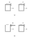
- FIG. 3 is a schematic diagram illustrating a configuration example of a first shutter 16 and a second shutter 17.
- FIG. It is a figure which shows the internal structural example of the banknote processing apparatus 900 which concerns on a comparative example.
- It is a flowchart which shows the example of a payment process which concerns on 1st Embodiment.
- FIG. 1 It is a figure for demonstrating the opening-and-closing state of the 1st shutter 16 and the 2nd shutter 17 in the case of a payment process. It is a flowchart which shows the example of a payment process which concerns on 2nd Embodiment. It is a flowchart which shows the example of a count process which concerns on 2nd Embodiment. It is a figure for demonstrating the relationship between the accumulated
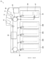
- FIG. 1 is a diagram illustrating an internal configuration example of the banknote handling apparatus 10 according to the first embodiment.
- the banknote handling apparatus 10 is installed in a financial institution or the like.
- the banknote handling apparatus 10 is a staff operation type terminal that transacts banknotes based on operations by staff such as reception desk staff of financial institutions that are operators of the apparatus.
- the banknote handling apparatus 10 includes a deposit port 12, a first withdrawal port 14, a second withdrawal port 15, a bill recognition unit 20, a temporary storage unit 22, and a transport unit 24. , Banknote cassettes 30A to 30D, banknote cassette 35 with reject box, and display unit 40.
- the deposit port 12 is a slot into which a staff member inserts banknotes.
- the deposit port 12 may be provided with a shutter (not shown) for opening and closing the opening.
- the deposit port 12 has a separating function for separating and feeding out banknotes inserted in a bundle one by one.
- the first withdrawal port 14 and the second withdrawal port 15 are discharge ports from which banknotes received by the staff are discharged (withdrawn).
- the first withdrawal port 14 and the second withdrawal port 15 have a stacking function for stacking the banknotes to be discharged.
- the 1st withdrawal port 14 and the 2nd withdrawal port 15 have the capacity
- two withdrawal openings are provided.
- the present invention is not limited to this. For example, there may be three or more withdrawal openings.
- the first withdrawal port 14 has a first withdrawal port shutter (hereinafter referred to as a first shutter) 16 that opens and closes the opening, and the second withdrawal port 15 has an opening.
- a second withdrawal opening shutter (hereinafter referred to as a second shutter) 17 is provided for opening and closing each.
- FIG. 2 is a schematic diagram showing a configuration example of the first shutter 16 and the second shutter 17.
- FIG. 2A shows a state where the first shutter 16 and the second shutter 17 are closed
- FIG. 2B shows a state where the first shutter 16 is opened.
- the first shutter 16 and the second shutter 17 move to close the first withdrawal port 14 and the second withdrawal port 15.
- the 1st shutter 16 is closed
- the 2nd shutter 17 is Closed.
- the planar first shutter 16 and the second shutter 17 are opened and closed by sliding, but the curved shutter may be rotated and opened.
- the banknote recognition unit 20 discriminates banknotes passing one by one.
- the traveling direction of the banknotes corresponds to both directions, and the banknote recognition unit 20 can distinguish between banknotes conveyed from the direction of the deposit port 12 and banknotes conveyed from the opposite direction.
- the banknote recognition unit 20 determines the denomination, authenticity (genuine / fake) of banknotes conveyed through the conveyance path, correctness (correction / non-conformity), and running state (normal / abnormal). ) And the like, and a normality judgment or a rejection judgment is performed on the passing banknote.
- a genuine note means one that has been differentiated from a banknote
- a counterfeit note means one that has not been differentiated from a banknote.
- a correct ticket is a banknote identified as a genuine note that is identified as suitable for deposit / withdrawal
- a non-performing note is a banknote identified as a genuine note that is not suitable for deposit / withdrawal. This is what has been identified.
- the rejection determination is performed based on factors such as counterfeit bills, damaged bills (stains, damages, outer shape anomalies, etc.), running abnormalities (skew bills, heavy runs, etc.).
- the reject banknote may include a banknote that cannot be handled as a withdrawal banknote (for example, a 2000 yen bill or a 5000 yen bill) or may include a foreign banknote.
- the temporary storage unit 22 has both functions of separating and accumulating banknotes.
- the temporary storage unit 22 temporarily accumulates the banknotes separated from the deposit port 12 and identified as normal by the banknote recognition unit 20 during the deposit transaction.
- the banknotes accumulated in the temporary storage unit 22 are paid out when a transaction is established, for example, when the account of the deposited banknote is confirmed, etc., and conveyed to the banknote cassettes 30A to 30D through the banknote recognition unit 20.
- the temporary storage unit 22 may be an accumulation type that sequentially stacks and accumulates banknotes, or may be a drum type that sequentially winds and stores banknotes.
- the transport unit 24 includes a transport path, a transport roller that transports banknotes, and a drive mechanism that drives the transport rollers, and transports banknotes one by one.
- the drive mechanism drives the transport roller by rotating a DC servo motor or a pulse motor, for example.
- the transport unit 24 is controlled by a control unit which will be described later, and transports banknotes to a target transport destination (for example, the first withdrawal port 14 or the second withdrawal port 15).
- the banknote cassettes 30A to 30D are banknote storage units that can store banknotes for each denomination and have both functions of stacking and separating banknotes.
- the banknote cassettes 30A to 30D may include a plurality of banknote cassettes for the same denomination.
- the bill cassettes 30A and 30C may be bill cassettes for 10,000 yen bills
- the bill cassettes 30B and 30D may be bill cassettes for thousand yen bills.
- the banknote cassettes 30A to 30D have a structure that can be attached to and detached from the banknote handling apparatus 10, and the banknote cassettes 30A to 30D can be loaded with banknotes by exchanging them individually.
- the banknote cassette 35 with a reject box (hereinafter also referred to as a banknote cassette 35) has a structure that can be attached to and detached from the banknote processing apparatus 10, and can be collected and replenished by individually replacing the banknote cassette 35. Moreover, the banknote cassette 35 is equipped with the banknote storage 36 on the upper side, and the rejection store
- the banknote storage 36 has a stacking function for stacking banknotes and a separating function for feeding one by one.
- the banknote storage 36 can collect banknotes separated from the banknote cassettes 30A to 30D at the time of cassette count collection and collect banknotes. Further, the banknote storage 36 can feed banknotes accumulated in the banknote storage 36 for replenishing the cassette count, and can replenish banknotes 30A to 30D with banknotes.
- the reject box 37 has only a stacking function for stacking banknotes.
- the reject warehouse 37 is a banknote storage unit for stacking banknotes (reject banknotes) that have been identified as abnormal (rejection determination) by the banknote recognition unit 20.
- Display unit 40 displays a menu screen and a processing result screen.
- the display unit 40 is realized by, for example, a CRT (Cathode Ray Tube) display device, a liquid crystal display (LCD) device, or an OLED (Organic Light Emitting Diode) device.
- CTR Cathode Ray Tube
- LCD liquid crystal display
- OLED Organic Light Emitting Diode
- the banknote handling apparatus 10 has an operation unit (not shown) that can be operated by a staff member.
- the banknote processing apparatus 10 performs a depositing process or a withdrawal process corresponding to a transaction of depositing or withdrawing by the staff operating the operation unit.
- the banknote processing apparatus 10 may process based on the operation of the staff in the reception terminal connected to the banknote processing apparatus 10 instead of an operation part.
- the banknote handling apparatus 10 performs, for example, deposit processing, withdrawal processing, replenishment processing, and collection processing as basic processing. Below, it demonstrates for every process, referring FIG.
- the deposit process is a process for accumulating the bills in the deposit port 12 in the bill processing apparatus 10.
- the banknote processing apparatus 10 performs, for example, a normal deposit process in which a deposited banknote is retracted to the temporary storage unit 22 and then accumulated from the temporary storage unit 22 into the banknote cassettes 30 ⁇ / b> A to 30 ⁇ / b> D and a received banknote to the temporary storage unit 22.
- a direct depositing process that directly accumulates in the banknote cassettes 30A to 30D without retreating is performed.
- the banknote handling apparatus 10 can select a normal deposit process or a direct deposit process depending on the setting.
- the normal deposit process will be described.
- banknotes inserted into the deposit port 12 are separated and fed one by one, and the fed banknotes are conveyed to the banknote recognition unit 20 by the conveyance unit 24.
- the banknote recognition unit 20 performs banknote discrimination, and banknotes whose discrimination result is normal are conveyed to the temporary storage unit 22 and accumulated. After that, when the deposit amount is fixed, the process proceeds to accumulation processing.
- the banknote (reject banknote) in which the discrimination result by the banknote recognition unit 20 is abnormal is accumulated in the first withdrawal port 14 or the second withdrawal port 15.
- the banknotes accumulated in the first withdrawal port 14 or the second withdrawal port 15 can be re-differentiated by the banknote recognition unit 20 by being reinserted into the deposit port 12 by the staff.
- banknotes are separated one by one from the temporary storage unit 22, and the separated banknotes are conveyed to the banknote recognition unit 20.
- the banknotes for which the discrimination result by the banknote recognition unit 20 is normal are accumulated in the banknote cassettes 30A to 30D corresponding to the denominations.
- banknotes for which the discrimination result by the banknote recognition unit 20 is abnormal such as running abnormal banknotes such as a dirty banknote, a folded banknote, and a skew banknote, are accumulated in the reject box 37 of the banknote cassette 35.
- the process proceeds to the return process.
- banknotes are separated one by one from the temporary holding unit 22, and the separated banknotes are conveyed to the banknote recognition unit 20. And even if the discrimination result by the banknote recognition part 20 is normal / abnormal, all the banknotes are accumulated in the 1st withdrawal port 14 or the 2nd withdrawal port 15.
- the banknote inserted into the deposit port 12 is identified by the banknote recognition unit 20 in the same manner as the normal deposit process.
- the banknotes for which the discrimination result is normal are accumulated in the banknote cassettes 30A to 30D corresponding to the denominations.
- banknotes (reject banknotes) whose discrimination results are abnormal are accumulated in the first withdrawal port 14 or the second withdrawal port 15.
- the banknotes accumulated in the first withdrawal port 14 or the second withdrawal port 15 can be re-differentiated by the banknote recognition unit 20 by being reinserted into the deposit port 12 by the staff.
- the withdrawal process is a process for accumulating the banknotes in the banknote cassettes 30A to 30D at the first withdrawal port 14 or the second withdrawal port 15.
- banknotes are separated and fed out from the banknote cassettes 30A to 30D one by one according to the designated amount, and the fed banknotes are transported to the banknote recognition section 20 by the transport section 24.
- the banknote recognition unit 20 performs banknote discrimination, and banknotes whose discrimination result is normal are accumulated in the first withdrawal port 14 or the second withdrawal port 15. Specifically, for example, depending on the denomination and number of normal banknotes to be withdrawn, the money is selectively accumulated (collected) at the first withdrawal port 14 or the second withdrawal port 15.
- banknotes with an abnormal discrimination result that is, banknotes that cannot be paid to the customer, are accumulated in the reject box 37 of the banknote cassette 35.
- the replenishment process is a process for replenishing the banknote processing apparatus 10 with banknotes.
- the banknote handling apparatus 10 as a specific replenishment method, a deposit port replenishment, a cassette replacement replenishment, and a cassette count replenishment are possible. Hereinafter, each replenishment method will be described.
- Replenishment of the deposit port is the same as the operation in the deposit process described above.
- banknotes fed out from the deposit port 12 and having a normal discrimination result by the banknote recognition unit 20 are evacuated to the temporary storage unit 22 and then accumulated in the banknote cassettes 30A to 30D corresponding to the denominations.
- the banknote whose discrimination result is abnormal is accumulated in the first withdrawal port 14 or the second withdrawal port 15.
- the cassette replacement replenishment utilizes the fact that the bill cassettes 30A to 30D are detachable, and the bill cassette loaded with bills in advance is exchanged with any of the bill cassettes 30A to 30D that have already been installed. To replenish. In cassette replacement replenishment, the operator must manually register the denomination and number of replenished banknotes.
- banknotes are loaded in advance into the banknote storage 36 of the banknote cassette 35 and set in the banknote processing apparatus 10.
- the banknotes fed out from the banknote storage 36 and having a normal discrimination result by the banknote recognition unit 20 are accumulated in the banknote cassettes 30A to 30D corresponding to the denominations.
- banknotes whose discrimination results are abnormal are accumulated in the reject box 37.
- the counting process is executed by the banknote recognition unit 20 in the cassette count replenishment, it is not necessary for the operator to manually register the denomination and the number of the replenished banknotes.
- the collection process is a process for collecting banknotes in the banknote processing apparatus 10.
- the banknote processing apparatus 10 as a specific collection method, withdrawal port collection, cassette exchange collection, and cassette count collection are possible. Hereinafter, each collection method will be described.
- the withdrawal port collection is the same as the operation in the withdrawal process described above.
- banknotes fed out from the banknote cassettes 30 ⁇ / b> A to 30 ⁇ / b> D to be collected and whose discrimination result by the banknote recognition unit 20 is normal are accumulated in the first withdrawal port 14 or the second withdrawal port 15.
- banknotes whose discrimination results are abnormal are accumulated in the reject box 37.
- the staff can collect the banknotes determined to be normal from the first withdrawal port 14 or the second withdrawal port 15. .
- the staff can collect the banknote determined to be abnormal from the reject box 37.
- the cassette exchange collection is performed by removing a predetermined banknote cassette from the banknote processing apparatus 10 among the banknote cassettes 30A to 30D.
- the operator needs to extract the banknotes from the removed banknote cassettes 30A to 30D and manually count the denomination and the number of the collected banknotes.
- the banknotes fed out of the banknote cassettes to be collected out of the banknote cassettes 30A to 30D and whose discrimination result by the banknote recognition unit 20 is normal are accumulated in the banknote storage 36 of the banknote cassette 35.
- banknotes whose discrimination results are abnormal are accumulated in the reject box 37.
- the staff removes only the banknote cassette 35 from the banknote processing apparatus 10, whereby the banknote determined to be normal and the banknote determined to be abnormal can be collected. Further, in the cassette counting and collecting, since the counting process is executed by the bill recognition unit 20, it is not necessary for the operator to manually count the denomination and the number of the collected bills.
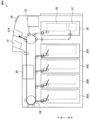
- FIG. 3 is a diagram illustrating an internal configuration example of the banknote handling apparatus 900 according to the comparative example.
- the banknote handling apparatus 900 has only one withdrawal port 914 and has two withdrawal openings (a first withdrawal opening 14 and a second withdrawal opening 15). And different.
- a large amount of banknotes separated from the banknote cassettes 30A to 30D is dispensed to one withdrawal port 914. In such a case, a case where the withdrawal process is stopped halfway occurs.
- one of the first withdrawal port 14 and the second withdrawal port 15 is dispensed during the withdrawal process.
- the banknotes are transferred from one withdrawal port to the other withdrawal port (for convenience).
- a second withdrawal port Referred to as a second withdrawal port
- an opening operation for opening the shutter of the first withdrawal port As a result, even if the number of banknotes accumulated at the first withdrawal port reaches the maximum accumulation number, the banknotes can be continuously conveyed to the second withdrawal port without stopping the withdrawal process.
- the banknotes accumulated in the first withdrawal port are extracted during the conveyance of the bills to the second withdrawal port. Since it is possible, a banknote can be efficiently extracted when carrying out a withdrawal process of a large amount of banknotes.
- FIG. 4 is a block diagram illustrating a functional configuration example of the banknote handling apparatus 10.
- the banknote handling apparatus 10 includes a control unit 70, a storage unit 80, and a detection unit 82.
- the control unit 70 controls the overall operation of the banknote handling apparatus 10. Specifically, the control unit 70 controls basic processes such as the above-described deposit process, withdrawal process, replenishment process, and recovery process. For example, the control unit 70 controls the conveyance of banknotes by the conveyance unit 24 and the opening / closing operations of the first shutter 16 and the second shutter 17.
- the control part 70 controls the 1st shutter 16 and the 2nd shutter 17 as follows, when dispensing a large amount of banknotes.
- the first shutter 16 corresponds to a first opening / closing member capable of opening / closing the first withdrawal port 14 by moving
- the second withdrawal port 15 can be opened / closed by moving the second shutter 17. It corresponds to a second opening / closing member.
- the banknotes are first conveyed to the first withdrawal port 14 out of the first withdrawal port 14 and the second withdrawal port 15 during the withdrawal process.
- the control unit 70 changes the banknote transport destination from the first withdrawal port 14 to the first.
- a switching operation for switching to the two withdrawal openings 15 and an opening operation for opening the first shutter 16 are performed.
- the control unit 70 changes the banknote transport destination from the first withdrawal port 14 to the second withdrawal port 15.
- the conveyance part 24 has members, such as a switching blade, in a conveyance path, and can be set to the 1st withdrawal port 14 or the 2nd withdrawal port 15 as a conveyance destination by rotating the switching blade, for example. .
- the banknotes can be conveyed to the second withdrawal port 15 without stopping the withdrawal process.
- opening the first shutter 16 after the transfer destination is switched it is possible to extract the banknotes accumulated in the first withdrawal port 14 while the banknotes are being transported to the second withdrawal port 15.
- the banknote can be efficiently extracted.
- the control unit 70 opens the first shutter 16 after switching the banknote transport destination from the first withdrawal port 14 to the second withdrawal port 15, but is not limited thereto.
- the controller 70 may switch the transport destination from the first withdrawal port 14 to the second withdrawal port 15 after opening the first shutter 16.
- the control unit 70 may open the first shutter 16 at the same time as switching the transport destination from the first withdrawal port 14 to the second withdrawal port 15. Even in such a case, a large amount of banknotes can be dispensed without stopping the withdrawal process.
- the timing which opens the 1st shutter 16 will be advanced, a staff becomes easy to extract the banknote integrated
- the control unit 70 moves the first shutter 16. Close operation is performed. Thereby, when the 1st shutter 16 is open, it can prevent that the banknote integrated
- the control unit 70 determines whether the first withdrawal port 14 and the second withdrawal port 14 are removed. 2 Stops the conveyance of banknotes to the withdrawal port 15. Thereby, it can prevent that the jam of a banknote etc. generate
- control unit 70 performs the transfer operation of the transport destination and the opening operation of the first shutter 16, and then the banknote stacking number of the second withdrawal port 15 reaches the maximum stacking number (100 sheets). Performs a switching operation for switching the transport destination from the second withdrawal port 15 to the first withdrawal port 14 and an opening operation for opening the second shutter 17.
- the control unit 70 performs the transfer operation of the transport destination and the opening operation of the first shutter 16, and then the banknote stacking number of the second withdrawal port 15 reaches the maximum stacking number (100 sheets).
- the storage unit 80 stores a program or the like for operating the banknote processing apparatus 10. Moreover, the memory
- the detection unit 82 includes, for example, an optical sensor and detects various states. For example, the detection unit 82 detects the banknote stacking state (the number of stacked banknotes or whether or not banknotes have been extracted) at the first and second withdrawal ports 14 and 15. Moreover, the detection part 82 can detect the conveyance state of a banknote.
- the banknote stacking state the number of stacked banknotes or whether or not banknotes have been extracted
- control unit 70 and the storage unit 80 described above may be realized by a hardware configuration including a CPU (Central Processing Unit), a ROM (Read Only Only Memory), a RAM (Random Access Memory), and the like.
- the CPU has a calculation function and a control function, and controls the overall operation of the banknote handling apparatus 10 according to various programs.
- the ROM stores programs used by the CPU, calculation parameters, and the like.
- the RAM temporarily stores programs used in the execution of the CPU, parameters that change as appropriate during the execution, and the like.
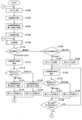
- FIG. 5 is a flowchart illustrating an example of a withdrawal process according to the first embodiment.
- FIG. 6 is a flowchart showing an example of a counting process of dispensed banknotes according to the first embodiment.
- FIG. 7 is a view for explaining the open / closed state of the first shutter 16 and the second shutter 17 during the withdrawal process.
- the flowchart in FIG. 5 is realized, for example, when the CPU of the control unit 70 executes a program stored in the ROM.
- the program to be executed may be stored in a recording medium such as a CD (Compact Disk), a DVD (Digital Versatile Disk), or a memory card, or may be downloaded from a server or the like via the Internet.
- the flowchart of FIG. 5 is started from an idle state of the withdrawal process, that is, a state where the first shutter 16 of the first withdrawal port 14 and the second shutter 17 of the second withdrawal port 15 are closed (Step S100). ).
- the control unit 70 has received an instruction for a withdrawal process from the operation unit of the banknote processing apparatus 10 operated by the staff or the reception terminal connected to the banknote processing apparatus 10 (step S102).
- the control unit 70 receives information on the banknote cassette for withdrawal and the number of withdrawals.
- control unit 70 sets the destination of the banknotes to be dispensed to either the first withdrawal port 14 or the second withdrawal port 15 (step S104).
- the transport destination is set to the first withdrawal port 14, but may be set to the second withdrawal port 15.
- control unit 70 starts a dispensing operation according to the instruction (step S106).
- the control unit 70 performs the withdrawal bill counting process shown in FIG. 6 (Step S108).
- the control unit 70 first determines whether or not the withdrawal banknote can be conveyed to the first withdrawal port 14 and the second withdrawal port 15 (steps S202, S204, and S206). And when the withdrawal banknote can be conveyed to the 1st withdrawal port 14 and the 2nd withdrawal port 15 (step S202: Yes, S204: Yes), the control part 70 is shown to Fig.7 (a). As described above, the first shutter 16 and the second shutter 17 are maintained in the shutter open / close state 1 (step S208). That is, the same state as when the withdrawal process is started is maintained.
- the control unit 70 conveys the withdrawal banknotes fed out from the banknote cassette to the banknote recognition unit 20, and conveys the withdrawal banknotes with normal discrimination results to the first withdrawal port 14. Thereafter, it is assumed that the detection unit 82 has detected that the maximum number of stacked banknotes (100 sheets) has been accumulated in the first withdrawal port 14 (detects the Full of the first withdrawal port 14) (step). S210). Then, the control part 70 switches the conveyance destination of a withdrawal banknote from the 1st withdrawal port 14 to the 2nd withdrawal port 15 (step S212). For example, the control unit 70 switches the transport destination without stopping the transport of banknotes by rotating the switching blade. Thereby, the withdrawal banknote is conveyed to the second withdrawal opening 15.
- the control unit 70 opens the first shutter 16 of the first withdrawal port 14 in which the withdrawal banknotes P are accumulated (step S214). Then, the control unit 70 maintains the shutter open / close state 2 in which the first shutter 16 is open and the second shutter 17 is closed (step S216). At this time, since the first shutter 16 is open, the staff can withdraw the withdrawal bills P accumulated in the first withdrawal opening 14.
- the withdrawal banknote is conveyed to the second withdrawal port 15.
- the control part 70 accumulated the withdrawal banknote of the maximum accumulation
- step S218 when the detecting unit 82 detects that the withdrawal banknotes accumulated in the first withdrawal port 14 are extracted (step S220). ), As shown in FIG. 7C, the control unit 70 closes the first shutter 16 of the first withdrawal port 14 from which the withdrawal banknote has been extracted (step S222). Then, the control unit 70 maintains the shutter open / close state 3 in which the first shutter 16 and the second shutter 17 are closed (step S224). At this time, the withdrawal banknote is conveyed to the second withdrawal port 15.
- step S226 when the controller 70 detects that the second withdrawal port 15 has become full in the shutter open / closed state 3 (step S226), the destination of the withdrawal banknote is transferred from the second withdrawal port 15 to the first withdrawal port 15. Switching to the mouth 14 (step S228). Thereby, the withdrawal banknote is conveyed to the first withdrawal opening 14.
- the control unit 70 opens the second shutter 17 of the second withdrawal port 15 in which the withdrawal banknotes P are accumulated (step S230). Then, the control unit 70 maintains the shutter open / close state 4 in which the first shutter 16 is closed and the second shutter 17 is open (step S232). At this time, since the second shutter 17 is open, the staff can withdraw the withdrawal banknote P accumulated in the second withdrawal opening 15.
- the control unit 70 determines whether or not the first withdrawal port 14 is Full before the withdrawal banknotes accumulated in the second withdrawal port 15 are extracted (Step S234). If the first withdrawal port 14 is full in step S234 (Yes), that is, if the first withdrawal port 14 and the second withdrawal port 15 are full as shown in FIG. Since the withdrawal banknote cannot be conveyed, the control unit 70 stops the counting process (S240).
- step S234 when the detection unit 82 detects that the withdrawal banknotes accumulated in the second withdrawal port 15 are extracted (step S236). ), The control unit 79 closes the second shutter 17 of the second withdrawal port 15 from which the withdrawal banknote has been extracted (step S238). Then, the control unit 70 maintains the shutter open / close state 1 in which the first shutter 16 and the second shutter 17 are closed (step S208).
- step S242 the control unit 70 stops the counting process (step S240).
- the processing of the flowchart of FIG. 6 is repeated until the counting processing is stopped. Then, when the counting process is stopped, the process returns to the flowchart of FIG. 5 and the withdrawal process is continued. That is, when the counting process in step S108 is stopped, the control unit 70 determines a stop factor of the withdrawal of the withdrawal banknote (step S110).
- the stop factor is whether the first withdrawal port 14 and the second withdrawal port 15 are full, or whether the withdrawal of the withdrawal banknote is completed.
- step S110 when the stop factor is the first withdrawal port 14 and the second withdrawal port 15 is Full, the control unit 70 detects withdrawal of the withdrawal bill (step S112). At this time, the first shutter 16 and the second shutter 17 are open. Then, the control unit 70 determines whether the withdrawal banknote accumulated in either the first withdrawal port 14 or the second withdrawal port 15 has been extracted (step S114).
- step S114 When the withdrawal banknote is extracted from the first withdrawal port 14 in step S114, the withdrawal banknote can be transported to the first withdrawal port 14, so the control unit 70 sets the transport destination of the withdrawal banknote as the first destination.
- the withdrawal port 14 is set (step S116), and the first shutter 16 is closed (step S118). Thereafter, the control unit 70 performs the counting process again (step S108).
- the shutter opening / closing state 4 in step S232 is set.
- step S114 when the withdrawal banknote of the 2nd withdrawal port 15 is extracted at step S114, since the withdrawal banknote can be conveyed to the 2nd withdrawal port 15, the control part 70 is the destination of the withdrawal banknote. Is set to the second withdrawal port 15 (step S120), and the second shutter 17 is closed (step S122). Thereafter, the control unit 70 performs the counting process again (step S108). In this case, in the flowchart of FIG. 6, the shutter opening / closing state 2 in step S216 is set.
- the control unit 70 determines whether the delivery destination when the counting process is stopped is the first withdrawal port 14 or the second withdrawal port 15. Determination is made (step S124). When the transport destination is the first withdrawal port 14 in step S124, the control unit 70 opens the first shutter 16 so that the withdrawal banknotes from the first withdrawal port 14 can be extracted. (Step S126). On the other hand, when the transport destination is the second withdrawal port 15 in step S124, the control unit 70 moves the second shutter 17 so that the withdrawal banknote can be extracted from the second withdrawal port 15. Open (step S128).
- control unit 70 detects withdrawal of the withdrawal banknote (step S130). At this time, either the first shutter 16 or the second shutter 17 is open. And the control part 70 determines whether the payment banknote integrated
- step S132 when the withdrawal banknote of the first withdrawal port 14 is extracted, the control unit 70 closes the opened first shutter 16 (step S134). On the other hand, when the withdrawal banknote of the second withdrawal port 15 is extracted in step S132, the control unit 70 closes the opened second shutter 17 (step S136).
- the control unit 70 determines whether or not the withdrawal banknotes are accumulated in both the first withdrawal port 14 and the second withdrawal port 15 (the first withdrawal port 14 and the second withdrawal port 15 are Empty). It is determined whether or not (step S138). If the first withdrawal port 14 and the second withdrawal port 15 are not empty in step S138 (No), that is, the withdrawal banknotes are accumulated in the withdrawal port from which the withdrawal banknotes are not extracted in step S132. If it is, the control unit 70 returns to step S130 and detects the withdrawal of the withdrawal banknote again.
- control part 70 returns to the idle state of Step S100. Thereby, a series of withdrawal processing is completed.
- the control unit 70 receives information on the banknote cassette to be withdrawn and the number of withdrawals, but may receive information on the type of withdrawal and the number of withdrawals.
- Second Embodiment> In the first embodiment described above, when the number of stacked banknotes stacked at the first withdrawal port 14 reaches the maximum number of stacked sheets, the control unit 70 changes the banknote transport destination from the first withdrawal port 14 to the second. While switching to the withdrawal port 15, the first shutter 16 of the first withdrawal port 14 was opened.
- the control part 70 changes the number of the banknotes (unpaid banknote) conveyed after switching a conveyance destination to the 2nd withdrawal port 15, and the 2nd withdrawal port 15 is set. And the timing of the opening operation of the first shutter 16 is made different depending on whether or not the number of banknotes is larger than the maximum number of stacked sheets. Thereby, the 1st shutter 16 can be opened at the optimal timing according to the number of unpaid banknotes conveyed after performing switching operation.
- the control unit 70 moves the first shutter 16 and the second shutter 17 after the conveyance of the banknotes to the second withdrawal port 15 is completed. Open at the same time.
- the control unit 70 opens the first shutter 16 together with the transfer destination switching operation. Thereby, when the number of banknotes is equal to or less than the maximum number of accumulated sheets, the first shutter 16 and the second shutter 17 are opened at the same time. It can be recognized that it has been transported to the withdrawal port 15.
- the first shutter 16 is opened together with the transfer destination switching operation, so that the banknotes are transferred to the first withdrawal port 14 while the second withdrawal port 15 is transporting bills. It becomes easy to extract the accumulated banknotes.
- FIG. 8 is a flowchart showing an example of a withdrawal process according to the second embodiment.
- FIG. 9 is a flowchart illustrating an example of a counting process according to the second embodiment.
- FIG. 10 is a diagram for explaining the relationship between the number of accumulated banknotes in the first withdrawal port 14 and the second withdrawal port 15 and the opening operation of the first shutter 16 and the second shutter 17.
- control unit 70 when receiving a withdrawal processing instruction, the control unit 70 starts a withdrawal operation according to the instruction and performs a counting process (steps S102 to S108). .
- the control unit 70 makes a withdrawal banknote (not yet) to the second withdrawal port 15. It is determined whether or not the number of (withdrawal banknotes) is larger than the maximum accumulated number (100) of the second withdrawal port 15 (step S262). If the number of undrawn banknotes is larger than the maximum number of accumulated bills in the second withdrawal port 15 in step S262 (Yes), the control unit 70 opens the first shutter 16 of the first withdrawal port 14. (Step S214). Since the 1st shutter 16 opens (refer to Drawing 7 (b)), when a withdrawal bill is conveyed to the 2nd withdrawal slot 15, a staff member withdraws the withdrawal banknote accumulated at the 1st withdrawal opening 14. Can be extracted.
- step S264 when the number of unpaid banknotes (here, 50) is equal to or less than the maximum number of sheets accumulated in the second withdrawal port 15 (No) in step S262, the control unit 70 makes the first shutter 16 The first shutter 16 and the second shutter 17 are closed and the shutter open / close state 5 is maintained (step S264). Thereby, when the withdrawal banknotes are conveyed to the second withdrawal opening 15, the staff cannot extract the withdrawal banknotes accumulated in the first withdrawal opening 14. As a result, when the delivery of the withdrawal banknote to the second withdrawal opening 15 is completed, the withdrawal banknotes are accumulated in the first withdrawal opening 14 and the second withdrawal opening 15 as shown in FIG. In the state, the counting process is stopped (step S240).
- the control unit 70 when switching the delivery destination of the withdrawal banknote from the second withdrawal port 15 to the first withdrawal port 14 in step S228, the control unit 70 also makes a withdrawal banknote (not yet sent to the first withdrawal port 14). It is determined whether or not the number of dispensed banknotes is greater than the maximum accumulated number (100 sheets) of the first withdrawal port 14 (step S266). If the number of unpaid banknotes is larger than the maximum accumulated number of the first withdrawal port 14 in step S266 (Yes), the control unit 70 opens the second shutter 17 (step S230).
- step S266 when the number of undrawn sheets is equal to or less than the maximum accumulated number in step S266 (No), the control unit 70 closes the first shutter 16 and the second shutter 17 without opening the second shutter 17.
- the shutter open / close state 6 is maintained (step S268). Thereby, when conveyance of the withdrawal banknote to the first withdrawal opening 14 is completed, the counting process is stopped in a state where the withdrawal banknotes are accumulated in the first withdrawal opening 14 and the second withdrawal opening 15. (Step S240).
- control unit 70 performs the processing of steps S112 to 122 in the same manner as in the first embodiment. Do.
- the control unit 70 processes the opening operation of the first shutter 16 and the second shutter 17 in parallel. That is, the control unit 70 determines whether or not the withdrawal banknotes are accumulated at the first withdrawal opening 14 (step S162), and the withdrawal banknotes are accumulated at the first withdrawal opening 14 at step S162. (Yes), the first shutter 16 is opened (step S164). At the same time, the control unit 70 determines whether or not the withdrawal banknotes are accumulated at the second withdrawal opening 15 (step S166), and the withdrawal banknotes are accumulated at the second withdrawal opening 15 at step S166. (Yes), the second shutter 17 is opened (step S168).
- the first withdrawal port 14 is caused by the number of undrawn banknotes being less than or equal to the maximum accumulated number of the first withdrawal port 14 and the second withdrawal port 15.
- both the first shutter 16 and the second shutter 17 (for example, simultaneously) ) Will open.
- the staff can recognize that, for example, all the withdrawal banknotes have been conveyed to the first withdrawal port 14 and the second withdrawal port 15.
- steps S130 to S138 Since the subsequent processing in steps S130 to S138 is the same as that in the first embodiment, detailed description thereof is omitted. Thereby, a series of withdrawal processing according to the second embodiment is completed.
- each step in the processing of the banknote processing apparatus 10 described above does not necessarily have to be processed in time series in the order described as a flowchart.
- each step in the processing of the banknote processing apparatus 10 may be processed in an order different from the order described as the flowchart, or may be processed in parallel.
- the banknote handling apparatus 10 is described as being applied to a staff operation type terminal.
- the present invention is not limited to this.
- the present invention may be applied to a cash processing unit of an automatic transaction apparatus represented by an ATM (Automated teller machine) that is a customer operation type terminal that recirculates (recycles) banknotes.
- ATM Automated teller machine
- Automatic transaction apparatuses are installed in various places such as banks, station premises, and convenience stores. The customer can perform transactions such as deposit, withdrawal and balance inquiry by performing various operations on the display screen displayed on the automatic transaction apparatus.
Landscapes
- Physics & Mathematics (AREA)
- General Physics & Mathematics (AREA)
- Business, Economics & Management (AREA)
- Engineering & Computer Science (AREA)
- Accounting & Taxation (AREA)
- Strategic Management (AREA)
- General Business, Economics & Management (AREA)
- Theoretical Computer Science (AREA)
- Computer Security & Cryptography (AREA)
- Finance (AREA)
- Pile Receivers (AREA)
- Separation, Sorting, Adjustment, Or Bending Of Sheets To Be Conveyed (AREA)
Description
(1-1.紙幣処理装置の内部構成例)
図1を参照しながら、第1の実施形態に係る紙幣処理装置10の内部構成例について説明する。
紙幣処置装置10は、基本処理として、例えば入金処理、出金処理、補充処理、回収処理を行う。以下では、図1を参照しながら処理毎に説明する。
入金処理は、入金口12の紙幣を紙幣処理装置10の内部に集積する処理である。紙幣処理装置10は、入金処理として、例えば、入金紙幣を一時保留部22へ退避させた後に一時保留部22から紙幣カセット30A~30Dに集積する通常入金処理と、入金紙幣を一時保留部22へ退避させないで直接紙幣カセット30A~30Dに集積するダイレクト入金処理とを行う。なお、紙幣処理装置10は、設定により通常入金処理又はダイレクト入金処理を選択することができる。
出金処理は、紙幣カセット30A~30Dの紙幣を第1出金口14又は第2出金口15に集積する処理である。
補充処理は、紙幣処理装置10に紙幣を補充する処理である。紙幣処理装置10においては、具体的な補充方法として、入金口補充、カセット交換補充、およびカセット計数補充が可能である。以下、各補充方法について説明する。
回収処理は、紙幣処理装置10内の紙幣を回収する処理である。紙幣処理装置10においては、具体的な回収方法として、出金口回収、カセット交換回収、およびカセット計数回収が可能である。以下、各回収方法について説明する。
次に、多量の紙幣を出金する際の問題点について、図3に示す比較例に係る紙幣処理装置900を例に挙げて説明する。
図4を参照しながら、紙幣処理装置10の機能構成例について説明する。図4は、紙幣処理装置10の機能構成例を示すブロック図である。図4に示すように、紙幣処理装置10は、制御部70と、記憶部80と、検知部82とを備える。
図5~図7を参照しながら、第1の実施形態に係る出金処理例について説明する。図5は、第1の実施形態に係る出金処理例を示すフローチャートである。図6は、第1の実施形態に係る出金紙幣の計数処理例を示すフローチャートである。図7は、出金処理の際の第1シャッタ16及び第2シャッタ17の開閉状態を説明するための図である。
上述した第1の実施形態によれば、出金処理の際に、第1出金口14と第2出金口15のうちの一方の出金口(以下では、第1出金口14を例に挙げて説明する)の紙幣の集積枚数が最大集積枚数に達した場合には、紙幣の搬送先を第1出金口14から第2出金口15へ切り替える動作と、第1出金口14の第1シャッタ16を開ける開動作とを行う。
なお、図5のフローチャートにおいて、制御部70は出金を行う紙幣カセットと出金枚数の情報を受け取るようにしたが、出金金種と出金枚数の情報を受け取るようにしてもよい。
上述した第1の実施形態では、制御部70は、第1出金口14に集積された紙幣の集積枚数が最大集積枚数に達すると、紙幣の搬送先を第1出金口14から第2出金口15へ切り替えると共に、第1出金口14の第1シャッタ16を開けていた。
Claims (10)
- 出金される紙幣を集積する第1出金口及び第2出金口と、
前記第1出金口又は前記第2出金口へ紙幣を搬送する搬送部と、
移動することにより前記第1出金口を開閉可能な第1開閉部材と、
移動することにより前記第2出金口を開閉可能な第2開閉部材と、
前記搬送部による前記紙幣の搬送と、前記第1開閉部材及び前記第2開閉部材の開閉動作とを制御する制御部と、
を備え、
前記制御部は、
出金処理の際に前記第1出金口の前記紙幣の集積枚数が最大集積枚数に達した場合には、前記紙幣の搬送先を前記第1出金口から前記第2出金口へ切り替える切替動作と、前記第1開閉部材を開ける開動作とを行う、紙幣処理装置。 - 前記制御部は、前記搬送先を前記第1出金口から前記第2出金口へ切り替えた後に、前記第1開閉部材を開ける、請求項1に記載の紙幣処理装置。
- 前記第1出金口又は前記第2出金口に集積された紙幣が抜け取られたことを検知する検知部を更に備え、
前記制御部は、前記切替動作と前記開動作を行った後に、前記第1出金口に集積された前記紙幣が抜き取られた場合には、前記第1開閉部材を閉める閉動作を行う、請求項1又は2に記載の紙幣処理装置。 - 前記制御部は、前記第2出金口への前記紙幣の搬送が完了する前に前記第1出金口に集積された前記紙幣が抜き取られない場合には、前記第1出金口及び前記第2出金口への前記紙幣の搬送を停止する、請求項3に記載の紙幣処理装置。
- 前記制御部は、
前記切替動作と前記開動作を行った後に、前記第2出金口の前記紙幣の集積枚数が最大集積枚数に達した場合には、
前記搬送先を前記第2出金口から前記第1出金口へ切り替える切替動作と、前記第2開閉部材を開ける開動作とを行う、請求項1~4のいずれか1項に記載の紙幣処理装置。 - 前記制御部は、前記第1開閉部材を開けた後に、前記搬送先を前記第1出金口から前記第2出金口へ切り替える、請求項1に記載の紙幣処理装置。
- 前記制御部は、前記搬送先を前記第1出金口から前記第2出金口へ切り替えると同時に、前記第1開閉部材を開ける、請求項1に記載の紙幣処理装置。
- 前記制御部は、
前記切替動作を行った後に搬送される紙幣の枚数と、前記第2出金口の最大集積枚数とを比較し、
前記紙幣の枚数が前記最大集積枚数よりも多いか否かに応じて、前記第1開閉部材の開動作のタイミングを異ならせる、請求項1~7のいずれか1項に記載の紙幣処理装置。 - 前記制御部は、
前記紙幣の枚数が前記最大集積枚数以下である場合には、前記第2出金口への前記紙幣の搬送が完了した後に、前記第1開閉部材と前記第2開閉部材を同時に開け、
前記紙幣の枚数が前記最大集積枚数よりも多い場合には、前記切替動作と共に前記第1開閉部材を開ける、請求項8に記載の紙幣処理装置。 - 第1出金口及び第2出金口で出金される紙幣の搬送と、前記第1出金口を開閉可能な第1開閉部材及び前記第2出金口を開閉可能な第2開閉部材の開閉動作と、を制御する紙幣処理方法であって、
前記第1出金口に前記紙幣を搬送するステップと、
出金処理の際に前記第1出金口に搬送された前記紙幣の集積枚数が最大集積枚数に達した場合には、前記紙幣の搬送先を前記第1出金口から前記第2出金口へ切り替える切替動作と、前記第1開閉部材を開ける開動作とを行うステップと、
切り替え後の前記第2出金口に前記紙幣を搬送するステップと、
を有する紙幣処理方法。
Priority Applications (4)
| Application Number | Priority Date | Filing Date | Title |
|---|---|---|---|
| CN201380037552.3A CN104471618B (zh) | 2012-08-09 | 2013-07-17 | 纸币处理装置以及纸币处理方法 |
| US14/417,136 US9842324B2 (en) | 2012-08-09 | 2013-07-17 | Banknote processing device, and banknote processing method |
| RU2015101614/08A RU2598987C1 (ru) | 2012-08-09 | 2013-07-17 | Устройство обработки банкнот и способ обработки банкнот |
| BR112015001731A BR112015001731A2 (pt) | 2012-08-09 | 2013-07-17 | dispositivo de processamento de cédulas e método de processamento de cédulas |
Applications Claiming Priority (2)
| Application Number | Priority Date | Filing Date | Title |
|---|---|---|---|
| JP2012-177066 | 2012-08-09 | ||
| JP2012177066A JP5954038B2 (ja) | 2012-08-09 | 2012-08-09 | 紙幣処理装置、及び紙幣処理方法 |
Publications (1)
| Publication Number | Publication Date |
|---|---|
| WO2014024652A1 true WO2014024652A1 (ja) | 2014-02-13 |
Family
ID=50067887
Family Applications (1)
| Application Number | Title | Priority Date | Filing Date |
|---|---|---|---|
| PCT/JP2013/069446 Ceased WO2014024652A1 (ja) | 2012-08-09 | 2013-07-17 | 紙幣処理装置、及び紙幣処理方法 |
Country Status (6)
| Country | Link |
|---|---|
| US (1) | US9842324B2 (ja) |
| JP (1) | JP5954038B2 (ja) |
| CN (1) | CN104471618B (ja) |
| BR (1) | BR112015001731A2 (ja) |
| RU (1) | RU2598987C1 (ja) |
| WO (1) | WO2014024652A1 (ja) |
Families Citing this family (9)
| Publication number | Priority date | Publication date | Assignee | Title |
|---|---|---|---|---|
| US9747638B2 (en) | 2015-02-27 | 2017-08-29 | Gieseke & Devrient America, Inc. | Systems, methods, and computer-readable media for electronic report tracking |
| US11410134B2 (en) * | 2015-02-27 | 2022-08-09 | Giesecke+Devrient Currency Technology America, Inc. | Systems, methods, and computer-readable media for reconciling deposits |
| JP6447570B2 (ja) * | 2016-05-11 | 2019-01-09 | 富士電機株式会社 | 紙幣処理装置 |
| JP6447571B2 (ja) * | 2016-05-11 | 2019-01-09 | 富士電機株式会社 | 紙幣処理装置 |
| TWI709114B (zh) * | 2015-11-13 | 2020-11-01 | 日商富士電機股份有限公司 | 紙幣處理裝置 |
| JP6481590B2 (ja) * | 2015-11-13 | 2019-03-13 | 富士電機株式会社 | 紙葉類処理装置 |
| CN105957238B (zh) | 2016-05-20 | 2019-02-19 | 聚龙股份有限公司 | 一种纸币管理方法及其系统 |
| CN106683269B (zh) * | 2016-12-23 | 2023-02-28 | 深圳怡化电脑股份有限公司 | 银行自助终端及其传钞控制系统和传钞控制方法 |
| JP6687094B2 (ja) * | 2018-12-04 | 2020-04-22 | 富士電機株式会社 | 紙幣処理装置 |
Citations (4)
| Publication number | Priority date | Publication date | Assignee | Title |
|---|---|---|---|---|
| JPH05193817A (ja) * | 1991-08-01 | 1993-08-03 | Oce Nederland Bv | 相互に上下に配置された支持体上にシートを堆積するための装置 |
| JPH0721442A (ja) * | 1993-06-30 | 1995-01-24 | Glory Ltd | 紙幣処理機 |
| JP2010231784A (ja) * | 2009-03-25 | 2010-10-14 | Glory Ltd | 貨幣処理装置及び貨幣処理方法 |
| JP2012118610A (ja) * | 2010-11-29 | 2012-06-21 | Glory Ltd | 貨幣入出金システム |
Family Cites Families (10)
| Publication number | Priority date | Publication date | Assignee | Title |
|---|---|---|---|---|
| US6860375B2 (en) * | 1996-05-29 | 2005-03-01 | Cummins-Allison Corporation | Multiple pocket currency bill processing device and method |
| JP3741893B2 (ja) * | 1999-03-10 | 2006-02-01 | ローレルバンクマシン株式会社 | 紙幣整理機 |
| JP3537697B2 (ja) * | 1999-03-10 | 2004-06-14 | ローレルバンクマシン株式会社 | 紙幣整理機 |
| JP3600762B2 (ja) | 1999-09-22 | 2004-12-15 | グローリー工業株式会社 | 循環式貨幣処理装置 |
| US20040139000A1 (en) * | 2000-05-05 | 2004-07-15 | Amos Carl Raymond | Advanced automatic instant money transfer machine |
| DE10210687A1 (de) * | 2002-03-12 | 2003-10-09 | Giesecke & Devrient Gmbh | Vorrichtung zur Bearbeitung von Banknoten |
| JP3968399B2 (ja) * | 2002-08-27 | 2007-08-29 | 旭精工株式会社 | 紙葉送り出し装置 |
| DE102006060619A1 (de) * | 2006-12-21 | 2008-06-26 | Adp Gauselmann Gmbh | Vorrichtung zur Entgegennahme und Ausgabe von papierartigen Zahlungsmitteln |
| US8408453B2 (en) * | 2007-06-11 | 2013-04-02 | Glory Ltd. | Money handling machine |
| JP5108087B2 (ja) * | 2008-02-27 | 2012-12-26 | グローリー株式会社 | 紙葉類処理装置 |
-
2012
- 2012-08-09 JP JP2012177066A patent/JP5954038B2/ja active Active
-
2013
- 2013-07-17 CN CN201380037552.3A patent/CN104471618B/zh not_active Expired - Fee Related
- 2013-07-17 US US14/417,136 patent/US9842324B2/en not_active Expired - Fee Related
- 2013-07-17 BR BR112015001731A patent/BR112015001731A2/pt not_active Application Discontinuation
- 2013-07-17 WO PCT/JP2013/069446 patent/WO2014024652A1/ja not_active Ceased
- 2013-07-17 RU RU2015101614/08A patent/RU2598987C1/ru active
Patent Citations (4)
| Publication number | Priority date | Publication date | Assignee | Title |
|---|---|---|---|---|
| JPH05193817A (ja) * | 1991-08-01 | 1993-08-03 | Oce Nederland Bv | 相互に上下に配置された支持体上にシートを堆積するための装置 |
| JPH0721442A (ja) * | 1993-06-30 | 1995-01-24 | Glory Ltd | 紙幣処理機 |
| JP2010231784A (ja) * | 2009-03-25 | 2010-10-14 | Glory Ltd | 貨幣処理装置及び貨幣処理方法 |
| JP2012118610A (ja) * | 2010-11-29 | 2012-06-21 | Glory Ltd | 貨幣入出金システム |
Also Published As
| Publication number | Publication date |
|---|---|
| US9842324B2 (en) | 2017-12-12 |
| JP5954038B2 (ja) | 2016-07-20 |
| BR112015001731A2 (pt) | 2017-07-04 |
| CN104471618B (zh) | 2017-03-22 |
| US20150235188A1 (en) | 2015-08-20 |
| RU2598987C1 (ru) | 2016-10-10 |
| JP2014035676A (ja) | 2014-02-24 |
| CN104471618A (zh) | 2015-03-25 |
Similar Documents
| Publication | Publication Date | Title |
|---|---|---|
| JP5954038B2 (ja) | 紙幣処理装置、及び紙幣処理方法 | |
| JP5821585B2 (ja) | 紙幣処理装置 | |
| JP5954037B2 (ja) | 紙幣処理装置、及び紙幣処理方法 | |
| JP5786694B2 (ja) | 紙幣処理装置 | |
| JP5626732B2 (ja) | 紙葉類取扱装置 | |
| JP5790450B2 (ja) | 紙幣処理装置 | |
| JP5760984B2 (ja) | 紙幣処理装置 | |
| JP5900251B2 (ja) | 紙幣処理装置 | |
| JP6089977B2 (ja) | 現金処理装置 | |
| JP5888170B2 (ja) | 紙幣処理装置 | |
| JP5904048B2 (ja) | 紙幣処理装置、及び紙幣処理方法 | |
| KR101781304B1 (ko) | 매체 보관 장치와 이를 구비한 금융기기 및 금융기기의 제어방법 | |
| JP2014035675A (ja) | 紙幣処理装置、及び紙幣処理方法 | |
| WO2018116620A1 (ja) | 紙幣処理装置 |
Legal Events
| Date | Code | Title | Description |
|---|---|---|---|
| 121 | Ep: the epo has been informed by wipo that ep was designated in this application |
Ref document number: 13828454 Country of ref document: EP Kind code of ref document: A1 |
|
| ENP | Entry into the national phase |
Ref document number: 2015101614 Country of ref document: RU Kind code of ref document: A |
|
| WWE | Wipo information: entry into national phase |
Ref document number: 14417136 Country of ref document: US |
|
| NENP | Non-entry into the national phase |
Ref country code: DE |
|
| REG | Reference to national code |
Ref country code: BR Ref legal event code: B01A Ref document number: 112015001731 Country of ref document: BR |
|
| 122 | Ep: pct application non-entry in european phase |
Ref document number: 13828454 Country of ref document: EP Kind code of ref document: A1 |
|
| ENP | Entry into the national phase |
Ref document number: 112015001731 Country of ref document: BR Kind code of ref document: A2 Effective date: 20150126 |