WO2014021236A1 - 気象再現方法、気象再現装置及び空気利用装置 - Google Patents
気象再現方法、気象再現装置及び空気利用装置 Download PDFInfo
- Publication number
- WO2014021236A1 WO2014021236A1 PCT/JP2013/070400 JP2013070400W WO2014021236A1 WO 2014021236 A1 WO2014021236 A1 WO 2014021236A1 JP 2013070400 W JP2013070400 W JP 2013070400W WO 2014021236 A1 WO2014021236 A1 WO 2014021236A1
- Authority
- WO
- WIPO (PCT)
- Prior art keywords
- temperature
- weather
- weather information
- area
- narrow
- Prior art date
- Legal status (The legal status is an assumption and is not a legal conclusion. Google has not performed a legal analysis and makes no representation as to the accuracy of the status listed.)
- Ceased
Links
Images






Classifications
-
- G—PHYSICS
- G01—MEASURING; TESTING
- G01W—METEOROLOGY
- G01W1/00—Meteorology
- G01W1/10—Devices for predicting weather conditions
-
- F—MECHANICAL ENGINEERING; LIGHTING; HEATING; WEAPONS; BLASTING
- F03—MACHINES OR ENGINES FOR LIQUIDS; WIND, SPRING, OR WEIGHT MOTORS; PRODUCING MECHANICAL POWER OR A REACTIVE PROPULSIVE THRUST, NOT OTHERWISE PROVIDED FOR
- F03D—WIND MOTORS
- F03D17/00—Monitoring or testing of wind motors, e.g. diagnostics
-
- G—PHYSICS
- G01—MEASURING; TESTING
- G01W—METEOROLOGY
- G01W1/00—Meteorology
- G01W1/02—Instruments for indicating weather conditions by measuring two or more variables, e.g. humidity, pressure, temperature, cloud cover or wind speed
-
- F—MECHANICAL ENGINEERING; LIGHTING; HEATING; WEAPONS; BLASTING
- F05—INDEXING SCHEMES RELATING TO ENGINES OR PUMPS IN VARIOUS SUBCLASSES OF CLASSES F01-F04
- F05B—INDEXING SCHEME RELATING TO WIND, SPRING, WEIGHT, INERTIA OR LIKE MOTORS, TO MACHINES OR ENGINES FOR LIQUIDS COVERED BY SUBCLASSES F03B, F03D AND F03G
- F05B2260/00—Function
- F05B2260/82—Forecasts
- F05B2260/821—Parameter estimation or prediction
- F05B2260/8211—Parameter estimation or prediction of the weather
Definitions
- the present invention relates to a weather reproduction method and a weather reproduction device that reproduces meteorological data in a region narrower than the weather data using past weather data, and in particular, an air utilization device arranged at a point where there is no weather observation data.
- the present invention relates to a weather reproduction method for reproducing weather data, a weather reproduction device, and an air utilization device for designing.
- air utilization devices that are arranged outdoors and are affected by the surrounding weather conditions and that use air as a heat source or cold source, power source, and / or reactant.
- An example of an air utilization device that utilizes air as a cold heat source is an air fin cooler.
- An air utilization apparatus used as a power source is a wind power generator.
- apparatuses that use air as a reactant include a gas turbine that causes a combustion reaction, and a reactor that performs an oxidation reforming reaction.
- design pressure or design temperature In the industrial field, rotating machines, heat exchangers, pressure vessels, etc. are designed to operate safely within a specific pressure or temperature called design pressure or design temperature, but the actual operating temperature of the equipment is If the design temperature is exceeded, it becomes difficult to obtain the desired performance. For example, if it is a gas turbine, it will become lower than desired output, and if it is an air cooling type heat exchanger, it will become lower than the desired heat exchange amount.
- the amount of exhaust gas from the gas turbine is a function of on-site weather conditions (temperature, pressure and humidity), so based on multiple weather data, generate an emission output notification that includes the generated emission level
- a method for predicting the discharge amount of a gas turbine is disclosed (the following Patent Document 1).
- the disclosed prediction method when a user desires prediction of weather conditions, the weather condition near the gas turbine is predicted by accessing a third party weather system or the like and interpolating the data received from the weather service together with the received data. . In this way, the disclosed prediction method predicts the weather when there is no future weather data.
- Patent Document 2 a weather prediction using a weather simulation (the following Patent Document 2) or a technique relating to a diffusion prediction of radioactive substances (the following Patent Document 3) is disclosed.
- Item A1 Weather reproduction that reproduces the weather by weather simulation to design an air utilization device that is placed outdoors and is affected by ambient weather conditions and uses air as either a heat source, power source, or reactant
- a method Meteorological information set related to a plurality of times within a predetermined period in a first region including a location where the air utilization device is arranged, from a plurality of weather information including at least temperature data and related to the area and time Select multiple Using the selected plurality of weather information sets as input data, solving a differential equation of the weather information according to an analysis model for weather simulation is related to a plurality of narrower second regions in the first region.
- the processor is The weather reproduction device according to claim 10, wherein the weather field information is used to calculate a flow in which warmed air exhaled by the air utilization device is recirculated to a suction portion of the air utilization device.
- Item A12 The weather reproduction device according to claim 11, wherein the processing unit determines the temperature margin based on the flow of the recirculation.
- the first narrow-area meteorological information set generation step uses the observation data including at least one of a wind direction, a wind speed, and a temperature of an area targeted by the meteorological information.
- the weather reproduction device according to any one of claims 8 to 12, wherein the set of information is recalculated. Item A14.
- the first and second narrow-area weather information is three-dimensional data and includes at least one of wind direction, wind speed, turbulent energy, solar radiation, atmospheric pressure, rainfall, humidity, and temperature.
- the weather reproduction apparatus according to claim 1.
- Item A15 An air utilization device that is arranged outdoors and is influenced by the surrounding weather conditions, and uses air as either a heat source, a power source, or a reactant, A suction part for sucking in the air; An operation unit that performs any one of heat exchange, reaction, and power recovery using the air sucked in the suction unit, A discharge unit for discharging the gas released by any of the heat exchange, reaction, and power recovery operations; Meteorological information set related to a plurality of times within a predetermined period in a first region including a location where the air utilization device is arranged, from a plurality of weather information including at least temperature data and related to the area and time Select multiple Using the selected plurality of weather information sets as input data, solving a differential equation of the weather information according to an analysis model for weather simulation is
- Generate multiple first narrow-area weather information sets Of the plurality of generated first narrow area weather information sets, select a second narrow area weather information set for the second area including the location, Using the temperature data included in the second narrow-area weather information set, generate a cumulative frequency distribution of temperature or an excess probability distribution of temperature in the certain period, (A) a temperature at which the cumulative frequency exceeds at least 50% from the cumulative frequency distribution of the temperature, (B) Temperature at which the probability of excess is at least less than 50% from the temperature excess probability distribution (c) Temperature relative to the temperature at which the cumulative frequency exceeds 50% or the temperature at which the excess probability is less than 50% Air utilization equipment designed based on the design temperature selected from the temperature with margin added. Item A16.
- the second narrow area meteorological information is calculated by a three-dimensional hydrodynamic equation to calculate meteorological field information in a region narrower than the second narrow area meteorological information, and designed based on the obtained design temperature.
- the air utilization device according to claim 15. Item A17. Using the weather field information, calculate the flow of warmed air exhaled by the air utilization device and recirculate to the suction portion of the air utilization device, The air utilization device according to claim 15 or 16, wherein the temperature margin is determined based on the recirculation flow, and the air utilization device is designed based on the obtained design temperature. Item A18.
- the first narrow area weather information set is regenerated using observation data including at least one of a wind direction, a wind speed, and a temperature of an area targeted by the weather information.
- the air utilization apparatus according to any one of claims 15 to 17, which is to calculate.
- the second set that solves the above problem is like the items described below.
- a method From a plurality of weather information related to time and area, including at least wind direction data, a region including an arrangement place where the air utilization device is arranged, and weather information related to a plurality of times over a period of time Select a set, Each of the sets of weather information is input data, a differential equation of the weather information according to a weather analysis model for weather simulation is solved, and the first narrow-area weather information related to a region narrower than the region of the weather information Generate a set From the first set of narrow-area weather information, select a second set of narrow-area weather information that targets the area including the location, A weather reproduction method characterized in that, in order to determine an arrangement direction of the air utilization device, a wind direction having the highest cumulative frequency is calculated using wind direction data included in the second narrow-area weather information set.
- the air utilization device is disposed in the region so that the gas discharged by the discharge unit of the air utilization device on the windward side is not sucked by the suction portion of the air utilization device on the leeward side.
- the meteorological reproduction method according to item B1 which generates a layout to be performed.
- the first narrow area weather information set generation step the first narrow area weather information set is regenerated using observation data including at least one of a wind direction, a wind speed, and a temperature of an area targeted by the weather information.
- the second narrow area weather information is calculated by a three-dimensional hydrodynamic equation, and the weather field information in a region narrower than the second narrow area weather information is calculated, In any one of items B1 to B3, including using the meteorological field information, calculating a flow in which the air exhaled and warmed by the air utilization device is recirculated to a suction portion of the air utilization device.
- the area where the air utilization device is arranged differs from the terrain of the weather information due to any one of leveling, land use, and equipment installation, it is based on the terrain information reflecting any of the leveling, land use, equipment installation
- the weather reproduction method according to any one of items B1 to B4 further comprising recalculating the first set of narrow-area weather information.
- the first and second narrow-area weather information is three-dimensional data, and includes at least one of wind direction, wind speed, turbulent energy, solar radiation, atmospheric pressure, rainfall, humidity, and temperature, and any of items B1 to B5
- B7. Weather reproduction that reproduces the weather by weather simulation to design an air utilization device that is placed outdoors and is affected by ambient weather conditions and uses air as either a heat source, power source, or reactant
- a device Meteorological information related to time and area, including at least the area where the air utilization device is arranged, obtained from a plurality of weather information including wind direction data, and related to a plurality of times over a certain period
- Each of the sets of weather information is input data, a differential equation of the weather information according to a weather analysis model for weather simulation is solved, and the first narrow-area weather information related to a region narrower than the region of the weather information Generate a set Selecting a second set of meteorological
- the processing unit based on the calculated wind direction, the gas discharged from the discharge unit of the air utilization device on the windward side in the area so that the suction unit of the air utilization device on the leeward does not suck the gas.
- the weather reproduction device according to item B7 which generates a layout diagram in which the air utilization device is arranged.
- the first narrow-area meteorological information set generation step uses the observation data including at least one of a wind direction, a wind speed, and a temperature of an area targeted by the meteorological information.
- Item 9 The weather reproduction device according to item B7 or 8, which recalculates the information set. B10.
- the processing unit calculates the second narrow-area weather information with a three-dimensional hydrodynamic equation, calculates weather field information in a narrower area than the weather data, In any one of items B7 to B9, including using the meteorological field information, calculating a flow in which the air exhaled and warmed by the air utilization device is recirculated to a suction portion of the air utilization device.
- the described weather reproduction device B11.
- the area where the air utilization device is arranged differs from the terrain of the weather information due to any one of leveling, land use, and equipment installation, it is based on the terrain information reflecting any of the leveling, land use, equipment installation
- the weather reproduction apparatus according to any one of items B7 to B10, further comprising recalculating the first narrow-area weather information set. B12.
- the first and second narrow-area weather information is three-dimensional data, and includes at least one of wind direction, wind speed, turbulent energy, solar radiation, atmospheric pressure, rainfall, humidity, and temperature, and any of items B7 to B11
- the weather reproduction apparatus according to claim 1.
- An air utilization device that is arranged outdoors and is influenced by the surrounding weather conditions, and uses air as either a heat source, a power source, or a reactant, A suction part for sucking in the air;
- An operation unit that performs any one of heat exchange, reaction, and power recovery using the air sucked in the suction unit, A discharge unit for discharging the gas released by any of the heat exchange, reaction, and power recovery operations; From a plurality of weather information related to time and area, including at least wind direction data, a region including an arrangement place where the air utilization device is arranged, and weather information related to a plurality of times over a period of time Select a set, Each of the sets of weather information is input data, a differential equation of the weather information according to a weather analysis
- the disclosed weather reproduction method and the weather reproduction device have a plurality of times including a region including an arrangement place where the air utilization device is arranged and a certain period even when there is no weather data of the place where the air utilization device is installed.
- the temperature required for the design can be obtained based on the weather that is reproduced by performing the weather simulation on the region including the place where the meteorological information related to is input data.
- meteorological analysis model includes various physical models, and by solving them with a computer, weather simulation with high spatial resolution can be performed to perform weather simulation.
- the advantage of weather simulation is that it can estimate weather information with higher spatial resolution than field observations.
- wide area weather information weather information about a wide area including an area where the air utilization device is arranged
- NOAA National Centers for Environmental Prediction
- NCEP data as wide-area meteorological information is based on meteorological elements (wind direction, wind speed, turbulent energy, solar radiation, atmospheric pressure, etc.) on a three-dimensional grid point when the world is divided into a grid (grid spacing is 1.5 to 400 km).
- the physical model included in the weather analysis model is, for example, WRF (The Weather Research & Forecasting Model).
- the WRF includes various physical models. Physical models include radiation models that calculate solar radiation and atmospheric radiation, turbulence models that represent turbulent mixed layers, ground surface temperature, soil temperature, soil moisture content, snow cover, and ground surface flux. There are surface models.
- the meteorological analysis model described partial differential equations representing fluid motion in the atmosphere, including Naviestokes' equations related to fluid motion and empirical equations derived from atmospheric observation results, and conservation laws for mass and energy
- a weather simulation can be executed by including the partial differential equation and solving the differential equation simultaneously. Therefore, by using the regional weather information as the input data as the initial value and boundary value, solving the differential equation according to the weather analysis model for the weather simulation, the air utilization device related to the area of spatial resolution narrower than the regional weather information
- the weather information of the arrangement area can be generated.
- the weather information generated in this way is referred to as “narrow area weather information”.
- Computational fluid analysis is a computational fluid dynamics (Computational) that solves equations related to fluid motion using a computer. This is a numerical analysis and simulation method that observes flow by applying Fluid Dynamics. Specifically, the fluid state is calculated spatially by the Finite Volume Method using the Naviestokes equation, which is a fluid dynamic equation.
- the numerical fluid analysis procedure includes 3D model data creation process that reproduces the structure of the facility to be examined, a grid generation process that divides the examination target range into a grid that is the minimum calculation unit, and a computer. Including a step of taking in values and boundary values, solving a hydrodynamic equation in each lattice, and outputting various values (flow velocity, pressure, etc.) obtained as a result of the analysis as an image such as contour display or vector display.
- Numerical fluid analysis can realize fluid simulation with higher resolution than the weather analysis model, so it is very difficult to reproduce by weather simulation, and small changes in wind speed and direction, and several centimeters to several meters scale It is possible to provide information on the air flow phenomenon peculiar to the spatial scale, such as the change of the air flow around the building from the disturbance of the air flow.
- the weather reproduction device performs a weather analysis model and a numerical fluid analysis to calculate narrow-area weather information in which the air utilization device is arranged.
- the weather reproduction device may perform a design temperature calculation process or a wind map generation process, which will be described later.
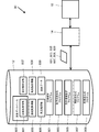
- FIG. 1A is a diagram illustrating an example of a functional configuration of a weather reproduction device.
- a weather reproduction device 90 illustrated in FIG. 1A includes a storage unit 12 that stores data and programs, and a processing unit 14 that performs numerical calculation processing.
- the storage unit 12 includes a weather analysis program 901 such as WRF, a numerical fluid analysis program 903, a design temperature calculation program 905, a wind map generation program 907, a drawing output program 909 for generating a layout map, a weather database 800, NCEP data, and the like.
- Wide area weather information 801, narrow area weather information 803 obtained by weather simulation, airflow field information 805 obtained by numerical fluid analysis, temperature analysis data 807, wind direction analysis data 808, and layout map data 809 are stored.
- the weather database holds wide-area weather data 801 and is downloaded from outside or obtained through a storage medium.
- the processing unit 14 executes the weather analysis program 901 to generate the narrow area weather information 803 from the wide area weather information 801 and perform the weather analysis process stored in the storage unit 12. Further, the processing unit 14 executes the numerical fluid analysis program 903 to generate the airflow field data 807 from the narrow area weather information 803 and perform numerical fluid processing stored in the storage unit 12. Similarly, the processing unit 14 executes a design temperature calculation program 905 and an airflow chart generation program 907, and executes a design temperature calculation process and an airflow chart generation process, which will be described later, and related temperature analysis data. 807 and wind direction analysis data 809 are displayed on the display unit 16 that displays data such as images.
- the processing unit 14 executes the layout map generation program 909 and outputs layout map data 809 based on the wind direction analysis data 808.
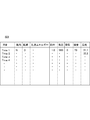
- FIG. 1B is a diagram showing an example of a data table of weather information.
- the data table shown in FIG. 1B shows the wide area weather information 801, but is also a data table applied to the narrow area weather information 803.
- the wide-area weather information includes the area targeted for the narrow-area weather information, and covers the broad-area weather information.
- the weather information is shown as a record set of a plurality of records composed of various data of wind direction, wind speed, turbulent energy, solar radiation, atmospheric pressure, rainfall, humidity, and temperature with time as a main key. .
- it is a weather information set classified by temperature
- the wide area weather information 801 and the narrow area weather information 803 are a plurality of weather information sets classified by area.
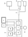
- FIG. 2 is a diagram illustrating an example of a hardware configuration of the weather reproduction device.
- the weather reproduction device 90 shown in FIG. 2 includes a processor 12A, a main storage device 14A, an auxiliary storage device 14B such as a hard disk or SSD (Solid State Drive), a drive device 15 that reads data from the storage medium 900, and a NIC (network A communication device 19 such as an interface card, and these components are connected to each other by a bus 20.
- the weather reproduction device 90 is connected to an external display 16 as an output device and an input device 17 such as a keyboard and a mouse.
- the processing unit 12 illustrated in FIG. 1A corresponds to the processor 12A
- the storage unit 14 corresponds to the main storage device 14A.
- the storage medium 900 stores the weather database 800, the weather analysis program 901, the numerical fluid analysis program 903, the design temperature calculation program 905, the wind map generation program 907, and the layout map generation program 909 shown in FIG. 1A as data. May be. These data 800 to 909 are stored in the storage unit 12 as shown in FIG. 1A.
- the weather reproduction device 90 may be connected to the external server 200 and the computers 210 and 220 via the network 40.
- the computer 210 and the external server 200 may have the same components as the weather reproduction device 90.
- the weather database 800 in the server 200 can be received via the network 40.
- only the weather analysis program 901 related to the weather simulation with a high system load is stored in the weather reproduction device 90, and the other programs are stored in either of the computers 210 and 220. It may be executed.
- the computer is limited to computer hardware, but the weather reproduction device 90 may be a virtual server in a data center.
- the hardware form may be such that the programs 901 to 909 are stored in the storage unit of the data center, are executed by the processing unit of the data center, and data is output from the data center to the client computer.
- the external server 200 may have a weather database. In that case, the weather reproduction device 90 acquires wide-area weather data from the external server 200.
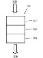
- FIG. 3A is a diagram illustrating an example of an air utilization device.
- the air utilization device 100 shown in FIG. 3A is disposed outdoors, is affected by the surrounding weather conditions, and utilizes air as one of a heat source, a power source, and a reactant.
- the air utilization device 100 is not necessarily an essential component, but the suction unit 101 that sucks in air, the operation unit 102 that performs any of heat exchange, reaction, and power recovery using the air sucked in the suction unit, A discharge unit 103 that discharges gas released by any of the operations of exchange, reaction, and power recovery is provided.
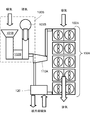
- FIG. 3B is a diagram showing a specific example of the air utilization device.
- FIG. 3B shows an air fin cooler 100A and a gas turbine 100B as examples of the air utilization device.
- the gas turbine 100B includes a suction unit 101B, an operation unit 102B, and a discharge unit (chimney) 103B.
- Combustible gas is burned by the operation unit 102B using the air sucked by the suction unit 101B, the turbine is rotated to generate a driving force, and the compressor 110A is rotated.
- the exhaust gas is exhausted from the chimney 103B.
- the gas compressed by the compressor 110A is supplied to the air fin cooler 100A.
- the illustrated operation unit 102B may be a reactor for the oxidation reforming reaction.
- the air fin cooler 100A cools the discharge gas heated by the compressor 110 by the heat exchanger 102A with the air sucked from the lower suction portion 101A (not shown), and the upper discharge portion 103A (see FIG. (Not shown).
- the compressed gas cooled by the air fin cooler 100A is cooled by the cooling device 120 to cool the medium to be cooled.
- the gas that has been decompressed and heated is returned to the compressor 110A again.
- the medium to be cooled is, for example, a hydrocarbon gas such as methane or ethane, and is liquefied by being cooled by the cooling device 120.
- the air utilization device has been described as either an air fin cooler or a gas turbine.
- the air utilization device is a liquefaction plant that liquefies hydrocarbon gas, which includes an air fin cooler and a gas turbine.
- hydrocarbon gas which includes an air fin cooler and a gas turbine.
- an example of a weather reproduction method or a weather reproduction device will be described in an example of an air fin cooler, a gas turbine, and a liquefaction plant, but an embodiment of the present invention is a weather reproduction method, Or, it includes an air fin cooler, a gas turbine, and a liquefaction plant based on the layout designed by the weather reproduction device.
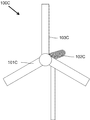
- FIG. 3C is a diagram showing another specific example of the air utilization device.
- a wind power generator 100C is shown as an example of the air utilization device.
- the propeller of the wind power generator 100C corresponds to the suction unit 101C and the discharge unit 103C, and the prime mover corresponds to the operation unit 102C.
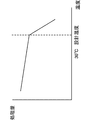
- FIG. 8A is a diagram illustrating an example of the relationship between the production amount of liquefied hydrocarbon gas and the design temperature in the liquefaction plant.
- the performance of the air utilization device 100 tends to decrease rapidly.
- the air fin cooler 100A is designed at the design temperature shown in FIG. 8A, when the outside air temperature exceeds the design temperature, the production amount of the liquefied hydrocarbon gas rapidly decreases.
- the predetermined performance cannot be satisfied.
- the weather reproduction device since the actual temperature is accurately simulated, even when the air utilization device 100 is designed in an environment where there is no actual measurement data, the outside air temperature is reproduced and the design temperature is obtained. Thus, it is possible to design an air utilization device having a desired performance.
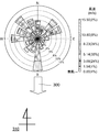
- FIG. 9 is a wind map obtained from the wind direction data of the narrow-area meteorological information.
- a wind map is a figure showing the direction of wind and the frequency of wind speed in a certain point at a certain period. The more it extends in the peripheral direction, the higher the cumulative frequency. Further, the wind speed at that time is also indicated by a shaded display or the like. The wind direction with the highest cumulative frequency obtained at this time is called the main wind direction.
- the main wind direction is indicated by 300.
- the direction symbol 310 corresponds to the main wind direction 300.
- the south (S) of the direction symbol indicates the main wind direction.
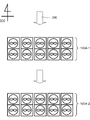
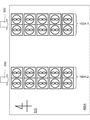
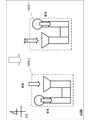
- FIG. 10A and FIG. 10B are diagrams showing the relationship between the main wind direction and the air fin cooler.
- the air fin coolers 100A-1 and 100A-2 shown in FIG. 10A are configured such that the gas discharged from the discharge unit of the air fin cooler 100A-1 that is upstream of the main wind direction 300 is the air fin cooler 100A- It arrange
- the air fin cooler 100A-2 uses the hot exhaust gas as the cooling gas, so that the desired heat exchange cannot be performed and the predetermined performance cannot be satisfied as shown in FIG. 8A.
- the above problem can be avoided by not arranging the air fin cooler so as to take in the exhaust downwind with respect to the wind direction with the highest cumulative frequency in the generated wind map. That is, on the basis of the calculated wind direction, the air fin cooler is arranged on the layout drawing so that the gas discharged by the discharge unit on the windward side is not sucked by the suction unit on the leeward side.
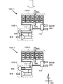
- FIG. 11A and 11B are diagrams showing the relationship between the main wind direction and the gas turbine.
- the gas exhausted by the exhaust part of the gas turbine 100B-1 located on the windward side with respect to the main wind direction 300 is sucked into the gas turbine 100B-2 located on the leeward side. It is arranged so that the part sucks.
- the gas turbine 100B-2 has a high possibility of using hot exhaust gas as suction gas, and a desired output cannot be obtained.
- the above-mentioned problem is avoided by not arranging the gas turbine so as to suck the exhaust downwind with respect to the wind direction with the highest cumulative frequency in the generated wind map. That is, based on the calculated wind direction, the gas turbine is arranged on the layout drawing so that the gas exhausted by the exhaust unit on the windward side is not sucked by the suction unit on the leeward side.
- the gas exhausted by the exhaust part of the gas turbine 100B-1 located on the windward side with respect to the main wind direction 300 is sucked into the gas turbine 100B-2 located on the leeward side. It is arranged so that the part does not inhale. When arranged in this manner, the gas turbine 100B-2 can satisfy a predetermined performance.
- the processing unit 14 is arranged so that the gas exhausted by the exhaust unit of the gas turbine 100B-1 is not sucked by the suction unit of the gas turbine 100B-2 in the leeward direction after calculating the main wind direction.
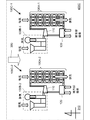
- FIG. 12A and 12B are diagrams showing the relationship between the main wind direction and a liquefaction plant including a gas turbine and an air fin cooler.
- the liquefaction plants 100C-1 and 100C-2 shown in FIG. 12A are configured to suck the exhaust gases of the air fin coolers 100A-1 and 100A-2 into the gas turbines 100B-1 and 100B-2, respectively.
- the liquefaction plants 100C-1 and 100C-2 shown in FIG. 12A with respect to the main wind direction 300, the gas discharged by the discharge part of the liquefaction plant 100C-1 that is on the windward side,
- the suction part is arranged so as to suck.
- the liquefaction plant 100C-1 has a high possibility of using hot exhaust gas as the suction gas, and the desired performance cannot be obtained.
- the above problem can be avoided by not arranging the liquefaction plant so that the exhaust air is sucked downwind with respect to the wind direction having the highest cumulative frequency in the generated wind map. That is, on the basis of the calculated wind direction, the liquefaction plant is arranged on the layout drawing so that the gas discharged by the discharge unit on the windward side is not sucked by the suction unit on the leeward side.
- the generation process (S104) calculates a temperature with a cumulative frequency exceeding at least 50% from the weather field information, calculates a temperature with an excess probability smaller than at least 50% from the weather field information, and
- the design temperature may be calculated by any one of the steps of adding a temperature margin to a temperature having an accumulated frequency exceeding 50% or a temperature having an excess probability smaller than 50%.
- FIG. 14 is a diagram illustrating an example of a flowchart of temperature analysis design.
- the illustrated steps S201 to S203 correspond to S101 to S103 in FIG.
- the processing unit 14 of the weather reproduction device 90 executes the wind map generation program and determines the arrangement direction of the air utilization device, using the wind direction data included in the second narrow-area weather information set, Processing for calculating the wind direction in which the cumulative frequency increases is performed (S204).
- the processing unit 14 of the weather reproduction device 90 executes the layout drawing generation program, and based on the calculated wind direction, the air use device discharges the gas discharged by the discharge discharge unit of the air use device on the windward side, A layout diagram for arranging the air utilization device in the area is generated so that the suction portion of the air utilization device in the leeward is not sucked.
- step (S204) the processing unit 14 executes the numerical fluid analysis program, calculates the second narrow area weather information using a three-dimensional hydrodynamic equation, and is narrower than the second narrow area weather information.
- the meteorological field information of the area is calculated, and using the meteorological field information, the flow of the air that has been exhaled and warmed by the air utilization device is recirculated to the suction portion of the air utilization device (S205).
- positioning of an air utilization apparatus can be determined based on the flow of recirculation.
Landscapes
- Engineering & Computer Science (AREA)
- Environmental & Geological Engineering (AREA)
- Life Sciences & Earth Sciences (AREA)
- Atmospheric Sciences (AREA)
- Biodiversity & Conservation Biology (AREA)
- Ecology (AREA)
- Environmental Sciences (AREA)
- Sustainable Development (AREA)
- Sustainable Energy (AREA)
- Chemical & Material Sciences (AREA)
- Combustion & Propulsion (AREA)
- Mechanical Engineering (AREA)
- General Engineering & Computer Science (AREA)
- Management, Administration, Business Operations System, And Electronic Commerce (AREA)
- Air Conditioning Control Device (AREA)
Description
領域及び時刻に関係付けられ、少なくとも温度データを含む複数の気象情報から、前記空気利用装置が配置される配置場所を含む第1領域における、一定期間内の複数の時刻に関係づけられる気象情報セットを複数選択し、
前記選択された複数個の気象情報セットを入力データとして、気象シミュレーションのための解析モデルに従う前記気象情報の微分方程式を解いて、前記第1領域内のより狭い複数の第2領域に関係づけられる第1狭域気象情報セットを複数生成し、
前記生成した複数の第1狭域気象情報セットのうち、前記配置場所を含む第2領域を対象とする第2狭域気象情報セットを選択し、
前記空気利用装置の設計温度を算定するために、前記第2狭域気象情報セットに含まれる温度データを用いて、前記一定期間における温度の累積頻度分布又は温度の超過確率分布を生成することを備える気象再現方法。
項目A2.前記温度の累積頻度分布又は温度の超過確率分布は、
(a)前記温度の累積頻度分布から、少なくとも50%を超える累積頻度となる温度、
(b)前記温度の超過確率分布から、少なくとも50%より小さい超過確率となる温度
(c)前記50%を超える累積頻度となる温度又は前記50%より小さい超過確率となる温度に対して、温度マージンを加えた温度を、前記設計温度として含み、
前記温度の累積頻度分布又は温度の超過確率分布を出力すること、をさらに備える請求項1に記載の気象再現方法。
項目A3.前記第2狭域気象情報を、3次元の流体力学式で演算して、前記第2狭域気象情報より狭い領域の気象場情報を算定することをさらに備える、請求項1又は2に記載の気象再現装置。
項目A4.前記気象場情報を用いて、前記空気利用装置が吐き出した温められた空気が、前記空気利用装置の吸込み部に再循環する流れを算定すること、をさらに備える請求項3に記載の気象再現方法。
項目A5.前記再循環の流れに基づいて、前記温度マージンを決定する工程を含む請求項4に記載の気象再現方法。
項目A6.前記第1狭域気象情報のセット生成ステップは、前記気象情報が対象とする領域の風向、風速、温度の少なくとも1つを含む観測データを用いて、前記第1狭域気象情報のセットを再算定すること、をさらに備える請求項1~5の何れか1項に記載の気象再現方法。
項目A7.前記第1及び第2狭域気象情報は、3次元のデータであり、風向、風速、乱流エネルギー、日射、気圧、雨量、湿度、及び温度を少なくとも1つ含む、請求項1~6の何れか1項に記載の気象再現方法。
項目A8.屋外に配置されて、周囲の気象条件により影響を受けるとともに、空気を熱源、動力源、及び反応物の何れかとして利用する空気利用装置を設計するために、気象シミュレーションにより気象を再現する気象再現装置であって、
領域及び時刻に関係付けられ、少なくとも温度データを含む複数の気象情報を格納する記憶部と、
前記選択された複数個の気象情報セットを入力データとして、気象シミュレーションのための解析モデルに従う前記気象情報の微分方程式を解いて、前記第1領域内のより狭い複数の第2領域に関係づけられる第1狭域気象情報セットを複数生成し、
前記生成した複数の第1狭域気象情報セットのうち、前記配置場所を含む第2領域を対象とする第2狭域気象情報セットを選択し、
前記空気利用装置の設計温度を算定するために、前記第2狭域気象情報セットに含まれる温度データを用いて、前記一定期間における温度の累積頻度分布又は温度の超過確率分布を生成する処理部と、
を備える気象再現装置。
項目A9.前記温度の累積頻度分布又は温度の超過確率分布は、
(a)前記温度の累積頻度分布から、少なくとも50%を超える累積頻度となる温度、
(b)前記温度の超過確率分布から、少なくとも50%より小さい超過確率となる温度
(c)前記50%を超える累積頻度となる温度又は前記50%より小さい超過確率となる温度に対して、温度マージンを加えた温度を、前記設計温度として含み、
前記処理部は、
前記温度の累積頻度分布又は温度の超過確率分布を出力する、請求項8に記載の気象再現装置。
項目A10.前記処理部は、
前記第2狭域気象情報を、3次元の流体力学式で演算して、前記第2狭域気象情報より狭い領域の気象場情報を算定する、請求項8又は9に記載の気象再現装置。
項目A11.前記処理部は、
前記気象場情報を用いて、前記空気利用装置が吐き出した温められた空気が、前記空気利用装置の吸込み部に再循環する流れを算定する請求項10に記載の気象再現装置。
項目A12.前記処理部は、前記再循環の流れに基づいて、前記温度マージンを決定する請求項11に記載の気象再現装置。
項目A13.前記処理部は、前記第1狭域気象情報のセット生成ステップは、前記気象情報が対象とする領域の風向、風速、温度の少なくとも1つを含む観測データを用いて、前記第1狭域気象情報のセットを再算定する、請求項8~12の何れか1項に記載の気象再現装置。
項目A14.前記第1及び第2狭域気象情報は、3次元のデータであり、風向、風速、乱流エネルギー、日射、気圧、雨量、湿度、及び温度を少なくとも1つ含む、請求項8~13の何れか1項に記載の気象再現装置。
項目A15.屋外に配置されて、周囲の気象条件により影響を受けるとともに、空気を熱源、動力源、及び反応物の何れかとして利用する空気利用装置であって、
前記空気を吸い込む吸込み部、
前記吸込み部で吸込まれた空気を用いて熱交換、反応、及び動力回収の何れかをする操作部、
前記熱交換、反応、及び動力回収の何れかの操作により放出されるガスを吐き出す排出部を備え、
領域及び時刻に関係付けられ、少なくとも温度データを含む複数の気象情報から、前記空気利用装置が配置される配置場所を含む第1領域における、一定期間内の複数の時刻に関係づけられる気象情報セットを複数選択し、
前記選択された複数個の気象情報セットを入力データとして、気象シミュレーションのための解析モデルに従う前記気象情報の微分方程式を解いて、前記第1領域内のより狭い複数の第2領域に関係づけられる第1狭域気象情報セットを複数生成し、
前記生成した複数の第1狭域気象情報セットのうち、前記配置場所を含む第2領域を対象とする第2狭域気象情報セットを選択し、
前記第2狭域気象情報セットに含まれる温度データを用いて、前記一定期間における温度の累積頻度分布又は温度の超過確率分布を生成し、
(a)前記温度の累積頻度分布から、少なくとも50%を超える累積頻度となる温度、
(b)前記温度の超過確率分布から、少なくとも50%より小さい超過確率となる温度
(c)前記50%を超える累積頻度となる温度又は前記50%より小さい超過確率となる温度に対して、温度マージンを加えた温度から選定した設計温度に基づいて設計された空気利用装置。
項目A16.前記第2狭域気象情報を、3次元の流体力学式で演算して、前記第2狭域気象情報より狭い領域の気象場情報を算定して、得られた設計温度に基づいて設計された請求項15に記載の空気利用装置。
項目A17.前記気象場情報を用いて、前記空気利用装置が吐き出した温められた空気が、前記空気利用装置の吸込み部に再循環する流れを算定し、
前記再循環の流れに基づいて、前記温度マージンを決定して、得られた設計温度に基づいて設計された請求項15又は16に記載の空気利用装置。
項目A18.前記第1狭域気象情報のセット生成ステップは、前記気象情報が対象とする領域の風向、風速、温度の少なくとも1つを含む観測データを用いて、前記第1狭域気象情報のセットを再算定することである、請求項15~17の何れか1項に記載の空気利用装置。
時刻及び領域に関係付けられ、少なくとも風向データを含む複数の気象情報から、前記空気利用装置が配置される配置場所を含む領域、及び、ある期間を通した複数の時刻に関係づけられる気象情報のセットを選択し、
前記気象情報のセットの各々を入力データとして、気象シミュレーションのための気象解析モデルに従う前記気象情報の微分方程式を解いて、前記気象情報の領域より狭い領域に関係づけられる第1狭域気象情報のセットを生成し、
前記第1狭域気象情報のセットのうち、前記配置場所を含む領域を対象とする第2狭域気象情報のセットを選択し、
前記空気利用装置の配置方向を決定するために、前記第2狭域気象情報のセットに含まれる風向データを用いて、最も累積頻度が高くなる風向を算定することを特徴とする気象再現方法。
B2.前記算定した風向に基づいて、風上にある前記空気利用装置の排出部により排出したガスを、風下にある前記空気利用装置の吸込み部が吸い込まないように、前記領域に前記空気利用装置を配置する配置図を生成する項目B1に記載の気象再現方法。
B3.前記第1狭域気象情報のセット生成ステップは、前記気象情報が対象とする領域の風向、風速、温度の少なくとも1つを含む観測データを用いて、前記第1狭域気象情報のセットを再算定すること、をさらに備える項目B1又はB2に記載の気象再現方法。
B4.前記第2狭域気象情報を、3次元の流体力学式で演算して、前記第2狭域気象情報より狭い領域の気象場情報を算定し、
前記気象場情報を用いて、前記空気利用装置が吐き出して温められた空気が、前記空気利用装置の吸込み部に再循環する流れを算定することを含む、項目B1~B3の何れか1項に記載の気象再現方法。
B5.前記空気利用装置が配置される領域が、整地、土地利用、設備設置の何れかにより、前記気象情報の地形と異なる場合、前記整地、土地利用、設備設置の何れかを反映した地形情報に基づいて、前記第1狭域気象情報のセットを再算定することをさらに備える項目B1~B4の何れか1項に記載の気象再現方法。
B6.前記第1、及び第2狭域気象情報は、3次元のデータであり、風向、風速、乱流エネルギー、日射、気圧、雨量、湿度、及び温度を少なくとも1つ含む、項目B1~B5の何れか1項に記載の気象再現方法。
B7.屋外に配置されて、周囲の気象条件により影響を受けるとともに、空気を熱源、動力源、及び反応物の何れかとして利用する空気利用装置を設計するために、気象シミュレーションにより気象を再現する気象再現装置であって、
時刻及び領域に関係付けられ、少なくとも風向データを含む複数の気象情報から取得した前記空気利用装置が配置される配置場所を含む領域、及び、ある期間を通した複数の時刻に関係づけられる気象情報のセットを格納する記憶部と、
前記気象情報のセットを選択し、
前記気象情報のセットの各々を入力データとして、気象シミュレーションのための気象解析モデルに従う前記気象情報の微分方程式を解いて、前記気象情報の領域より狭い領域に関係づけられる第1狭域気象情報のセットを生成し、
前記第1狭域気象情報のセットのうち、前記配置場所を含む領域を対象とする第2気象情報のセットを選択し、
前記第2気象情報のセットに含まれる風向データを用いて、前記空気利用装置の配置方向を決定するために、最も累積頻度が高くなる風向を算定する処理部と、
を備える気象再現装置。
B8.前記処理部は、前記算定した風向に基づいて、風上にある前記空気利用装置の吐出部により排出したガスを、風下にある前記空気利用装置の吸込み部が吸い込まないように、前記領域に前記空気利用装置を配置する配置図を生成する項目B7に記載の気象再現装置。
B9.前記処理部は、前記第1狭域気象情報のセット生成ステップは、前記気象情報が対象とする領域の風向、風速、温度の少なくとも1つを含む観測データを用いて、前記第1狭域気象情報のセットを再算定する、項目B7又は8に記載の気象再現装置。
B10.前記処理部は、前記第2狭域気象情報を、3次元の流体力学式で演算して、前記気象データより狭い領域の気象場情報を算定し、
前記気象場情報を用いて、前記空気利用装置が吐き出して温められた空気が、前記空気利用装置の吸込み部に再循環する流れを算定することを含む、項目B7~B9の何れか1項に記載の気象再現装置。
B11.前記空気利用装置が配置される領域が、整地、土地利用、設備設置の何れかにより、前記気象情報の地形と異なる場合、前記整地、土地利用、設備設置の何れかを反映した地形情報に基づいて、前記第1狭域気象情報のセットを再算定することをさらに備える項目B7~B10の何れか1項に記載の気象再現装置。
B12.前記第1、及び第2狭域気象情報は、3次元のデータであり、風向、風速、乱流エネルギー、日射、気圧、雨量、湿度、及び温度を少なくとも1つ含む、項目B7~B11の何れか1項に記載の気象再現装置。
B13.屋外に配置されて、周囲の気象条件により影響を受けるとともに、空気を熱源、動力源、及び反応物の何れかとして利用する空気利用装置であって、
前記空気を吸い込む吸込み部、
前記吸込み部で吸込まれた空気を用いて熱交換、反応、及び動力回収の何れかをする操作部、
前記熱交換、反応、及び動力回収の何れかの操作により放出されるガスを吐き出す排出部を備え、
時刻及び領域に関係付けられ、少なくとも風向データを含む複数の気象情報から、前記空気利用装置が配置される配置場所を含む領域、及び、ある期間を通した複数の時刻に関係づけられる気象情報のセットを選択し、
前記気象情報のセットの各々を入力データとして、気象シミュレーションのための気象解析モデルに従う前記気象情報の微分方程式を解いて、前記気象情報の領域より狭い領域に関係づけられる第1狭域気象情報のセットを生成し、
前記第1狭域気象情報のセットのうち、前記配置場所を含む領域を対象とする第2狭域気象情報のセットを選択し、
前記第2狭域気象情報のセットに含まれる風向データを用いて、最も累積頻度が高くなる風向として算定した算定風向に基づいて、前記領域に配置されることを特徴とする空気利用装置。
B14.前記第2狭域気象情報のセットに含まれる風向データにおける風上にある前記排出部により排出したガスを、前記第2狭域気象情報のセットに含まれる風向データにおける風下にある前記吸込み部が吸い込まないように、配置される項目B13に記載の空気利用装置。
B15.前記第2狭域気象情報を、3次元の流体力学式で演算して、前記第2狭域気象情報より狭い領域の気象場情報を算定し、前記気象場情報を用いて、前記空気利用装置が吐き出して温められた空気が、前記空気利用装置の吸込み部に再循環する流れを算定し、
前記再循環が生じないように、前記領域に配置される項目B13又はB14に記載の空気利用装置。
気象解析モデルとは、様々な物理モデルを含み、それらをコンピュータで解くことで、空間解像度の高い気象の再現計算を行うことで、気象シミュレーションできる。気象シミュレーションの利点としては、現地観測に比べて、空間解像度の高い気象情報を推定することができる点にある。
Research & Forecasting Model)がある。WRFには、さまざまな物理モデルが含まれている。物理モデルには、日射量及び大気放射量を計算する放射モデル、乱流混合層を表現する乱流モデル、地表面温度、土壌温度、土中水分量、積雪量、地表面フラックスを算出する地表面モデルなどがある。
数値流体解析とは、流体の運動に関する方程式をコンピュータで解く、数値流体力学(Computational
Fluid Dynamics)を応用し、流れを観察する数値解析及びシミュレーション手法を言う。具体的には、流体力学式であるナビエストークス方程式を用い、有限体積法(Finite Volume Method)により空間的に流体の状況を算定する。数値流体解析の手順としては、検討対象とする施設の構造を再現した3Dモデルデータの作成工程、検討対象範囲を、計算最小単位となる格子に分割を行う格子生成工程、コンピュータを用いて、初期値、及び境界値を取り込み、各格子における流体力学式を解く工程、解析結果により得られる諸値(流速、圧力等)をコンター表示やベクトル表示などの画像として出力する出力工程を含む。
気象再現装置は、気象解析モデル、及び、数値流体解析を実施して、空気利用装置が配置される狭域の狭域気象情報を算定する。また、気象再現装置は、後述する設計温度算定処理、又は、風配図生成処理を行ってもよい。
図3Aは、空気利用装置の一例を示す図である。図3Aに示す空気利用装置100は、屋外に配置されて、周囲の気象条件により影響を受けるとともに、空気を熱源、動力源、及び反応物の何れかとして利用する。空気利用装置100は、必ずしも必須の構成要素ではないが、空気を吸い込む吸込み部101、吸込み部で吸込まれた空気を用いて熱交換、反応、及び動力回収の何れかをする操作部102、熱交換、反応、及び動力回収の何れかの操作により放出されるガスを吐き出す排出部103を備える。
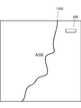
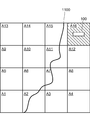
図4Aは、広域気象情報の一例を示す図である。図4Aには、日本地図上にある広域気象情報A100が示される。
図7Aは、狭域気象情報より得られた温度データと、風速データの一例を示す図である。狭域気象情報は、例えば、3年間の時間にわたり得られるが、図7Aでは例として2009年のデータを示す。
図8Aは、液化された炭化水素ガスの製造量と、設計温度の関係の一例を示す図である。空気利用装置100は、外気温が、設計温度以上の温度となった場合、空気利用装置100の性能は、急激に下げる傾向にある。例えば、図3の例において、エアフィンクーラ100Aが、図8Aに示す設計温度で設計された場合、外気温が設計温度を超える温度となると、液化炭化水素ガスの製造量が急激に下がるため、所定の性能を満たせなくなる。本実施形態に係る気象再現装置によれば、正確に実際の温度をシミュレートするので、実測データがない環境において空気利用装置100を設計する場合でも、外気温を再現し、設計温度を得ることで、所望の性能を有する空気利用装置の設計が可能になる。
図9は、狭域気象情報の風向データから得られる風配図である。風配図とは、ある地点のある期間における、各方位の風向および風速の頻度を表した図である。周囲方向に延びるほど、累積頻度が高い。また、そのときの風速も、網掛け表示などにより示される。この時得られる最も累積頻度が高い風向きを主風向という。図9では、主風向は、300で示される。方位記号310は、主風向300に対応する。以下に説明する図では、方位記号の南(S)が、主風向であることを示す。
図10A及び図10Bは、主風向とエアフィンクーラの関係を示す図である。図10Aに示すエアフィンクーラ100A-1、100A-2は、主風向300に対して、風上にあるエアフィンクーラ100A-1の排出部により排出したガスを、風下にあるエアフィンクーラ100A-2の吸込み部が吸い込むように配置される。このように配置される場合、エアフィンクーラ100A-2は、熱い排出ガスを冷却ガスとして利用するため、所望の熱交換が行えなくなり、図8Aに示したように、所定の性能を満たせなくなる。
図13は、温度解析設計のフローチャートの一例を示す図である。気象再現装置90の処理部14は、気象解析プログラムを実行して、時刻及び領域に関係付けられ、少なくとも温度データを含む複数の気象情報を含む気象データベースから、空気利用装置が配置される配置場所を含む領域、及び、ある期間を通した複数の時刻に関係づけられる気象情報のセットを選択する処理を行う(S101)。
図14は、温度解析設計のフローチャートの一例を示す図である。図示するステップS201~S203は、図13のS101~S103に相当する。気象再現装置90の処理部14は、風配図生成プログラムを実行して、空気利用装置の配置方向を決定するために、第2狭域気象情報のセットに含まれる風向データを用いて、最も累積頻度が高くなる風向を算定する処理を行う(S204)。さらに、気象再現装置90の処理部14は、配置図生成プログラムを実行して、算定した風向に基づいて、空気利用装置を、風上にある空気利用装置の吐出排出部により排出したガスを、風下にある前記空気利用装置の吸込み部が吸い込まないように、前記領域に前記空気利用装置を配置する配置図を生成する。
Claims (18)
- 屋外に配置されて、周囲の気象条件により影響を受けるとともに、空気を熱源、動力源、及び反応物の何れかとして利用する空気利用装置を設計するために、気象シミュレーションにより気象を再現する気象再現方法であって、
領域及び時刻に関係付けられ、少なくとも温度データを含む複数の気象情報から、前記空気利用装置が配置される配置場所を含む第1領域における、一定期間内の複数の時刻に関係づけられる気象情報セットを複数選択し、
前記選択された複数個の気象情報セットを入力データとして、気象シミュレーションのための解析モデルに従う前記気象情報の微分方程式を解いて、前記第1領域内のより狭い複数の第2領域に関係づけられる第1狭域気象情報セットを複数生成し、
前記生成した複数の第1狭域気象情報セットのうち、前記配置場所を含む第2領域を対象とする第2狭域気象情報セットを選択し、
前記空気利用装置の設計温度を算定するために、前記第2狭域気象情報セットに含まれる温度データを用いて、前記一定期間における温度の累積頻度分布又は温度の超過確率分布を生成することを備える気象再現方法。 - 前記温度の累積頻度分布又は温度の超過確率分布は、
(a)前記温度の累積頻度分布から、少なくとも50%を超える累積頻度となる温度、
(b)前記温度の超過確率分布から、少なくとも50%より小さい超過確率となる温度
(c)前記50%を超える累積頻度となる温度又は前記50%より小さい超過確率となる温度に対して、温度マージンを加えた温度を、前記設計温度として含み、
前記温度の累積頻度分布又は温度の超過確率分布を出力すること、をさらに備える請求項1に記載の気象再現方法。 - 前記第2狭域気象情報を、3次元の流体力学式で演算して、前記第2狭域気象情報より狭い領域の気象場情報を算定することをさらに備える、請求項1又は2に記載の気象再現装置。
- 前記気象場情報を用いて、前記空気利用装置が吐き出した温められた空気が、前記空気利用装置の吸込み部に再循環する流れを算定すること、をさらに備える請求項3に記載の気象再現方法。
- 前記再循環の流れに基づいて、前記温度マージンを決定する工程を含む請求項4に記載の気象再現方法。
- 前記第1狭域気象情報のセット生成ステップは、前記気象情報が対象とする領域の風向、風速、温度の少なくとも1つを含む観測データを用いて、前記第1狭域気象情報のセットを再算定すること、をさらに備える請求項1~5の何れか1項に記載の気象再現方法。
- 前記第1及び第2狭域気象情報は、3次元のデータであり、風向、風速、乱流エネルギー、日射、気圧、雨量、湿度、及び温度を少なくとも1つ含む、請求項1~6の何れか1項に記載の気象再現方法。
- 屋外に配置されて、周囲の気象条件により影響を受けるとともに、空気を熱源、動力源、及び反応物の何れかとして利用する空気利用装置を設計するために、気象シミュレーションにより気象を再現する気象再現装置であって、
領域及び時刻に関係付けられ、少なくとも温度データを含む複数の気象情報を格納する記憶部と、
前記選択された複数個の気象情報セットを入力データとして、気象シミュレーションのための解析モデルに従う前記気象情報の微分方程式を解いて、前記第1領域内のより狭い複数の第2領域に関係づけられる第1狭域気象情報セットを複数生成し、
前記生成した複数の第1狭域気象情報セットのうち、前記配置場所を含む第2領域を対象とする第2狭域気象情報セットを選択し、
前記空気利用装置の設計温度を算定するために、前記第2狭域気象情報セットに含まれる温度データを用いて、前記一定期間における温度の累積頻度分布又は温度の超過確率分布を生成する処理部と、
を備える気象再現装置。 - 前記温度の累積頻度分布又は温度の超過確率分布は、
(a)前記温度の累積頻度分布から、少なくとも50%を超える累積頻度となる温度、
(b)前記温度の超過確率分布から、少なくとも50%より小さい超過確率となる温度
(c)前記50%を超える累積頻度となる温度又は前記50%より小さい超過確率となる温度に対して、温度マージンを加えた温度を、前記設計温度として含み、
前記処理部は、
前記温度の累積頻度分布又は温度の超過確率分布を出力する、請求項8に記載の気象再現装置。 - 前記処理部は、
前記第2狭域気象情報を、3次元の流体力学式で演算して、前記第2狭域気象情報より狭い領域の気象場情報を算定する、請求項8又は9に記載の気象再現装置。 - 前記処理部は、
前記気象場情報を用いて、前記空気利用装置が吐き出した温められた空気が、前記空気利用装置の吸込み部に再循環する流れを算定する請求項10に記載の気象再現装置。 - 前記処理部は、前記再循環の流れに基づいて、前記温度マージンを決定する請求項11に記載の気象再現装置。
- 前記処理部は、前記第1狭域気象情報のセット生成ステップは、前記気象情報が対象とする領域の風向、風速、温度の少なくとも1つを含む観測データを用いて、前記第1狭域気象情報のセットを再算定する、請求項8~12の何れか1項に記載の気象再現装置。
- 前記第1及び第2狭域気象情報は、3次元のデータであり、風向、風速、乱流エネルギー、日射、気圧、雨量、湿度、及び温度を少なくとも1つ含む、請求項8~13の何れか1項に記載の気象再現装置。
- 屋外に配置されて、周囲の気象条件により影響を受けるとともに、空気を熱源、動力源、及び反応物の何れかとして利用する空気利用装置であって、
前記空気を吸い込む吸込み部、
前記吸込み部で吸込まれた空気を用いて熱交換、反応、及び動力回収の何れかをする操作部、
前記熱交換、反応、及び動力回収の何れかの操作により放出されるガスを吐き出す排出部を備え、
領域及び時刻に関係付けられ、少なくとも温度データを含む複数の気象情報から、前記空気利用装置が配置される配置場所を含む第1領域における、一定期間内の複数の時刻に関係づけられる気象情報セットを複数選択し、
前記選択された複数個の気象情報セットを入力データとして、気象シミュレーションのための解析モデルに従う前記気象情報の微分方程式を解いて、前記第1領域内のより狭い複数の第2領域に関係づけられる第1狭域気象情報セットを複数生成し、
前記生成した複数の第1狭域気象情報セットのうち、前記配置場所を含む第2領域を対象とする第2狭域気象情報セットを選択し、
前記第2狭域気象情報セットに含まれる温度データを用いて、前記一定期間における温度の累積頻度分布又は温度の超過確率分布を生成し、
(a)前記温度の累積頻度分布から、少なくとも50%を超える累積頻度となる温度、
(b)前記温度の超過確率分布から、少なくとも50%より小さい超過確率となる温度
(c)前記50%を超える累積頻度となる温度又は前記50%より小さい超過確率となる温度に対して、温度マージンを加えた温度から選定した設計温度に基づいて設計された空気利用装置。 - 前記第2狭域気象情報を、3次元の流体力学式で演算して、前記第2狭域気象情報より狭い領域の気象場情報を算定して、得られた設計温度に基づいて設計された請求項15に記載の空気利用装置。
- 前記気象場情報を用いて、前記空気利用装置が吐き出した温められた空気が、前記空気利用装置の吸込み部に再循環する流れを算定し、
前記再循環の流れに基づいて、前記温度マージンを決定して、得られた設計温度に基づいて設計された請求項15又は16に記載の空気利用装置。 - 前記第1狭域気象情報のセット生成ステップは、前記気象情報が対象とする領域の風向、風速、温度の少なくとも1つを含む観測データを用いて、前記第1狭域気象情報のセットを再算定することである、請求項15~17の何れか1項に記載の空気利用装置。
Priority Applications (6)
| Application Number | Priority Date | Filing Date | Title |
|---|---|---|---|
| AU2013297556A AU2013297556B2 (en) | 2012-07-31 | 2013-07-28 | Weather Predicting Method, Weather Predicting Apparatus, and Air Utilizing Apparatus |
| US14/389,769 US9753184B2 (en) | 2012-07-31 | 2013-07-28 | Weather predicting method, weather predicting apparatus, and air utilizing apparatus |
| AP2014008041A AP2014008041A0 (en) | 2012-07-31 | 2013-07-28 | Weather predicting method, weather predicting apparatus, and air utilizing apparatus |
| JP2014528129A JP6192644B2 (ja) | 2012-07-31 | 2013-07-28 | 気象再現方法及び気象再現装置 |
| RU2014145570/28A RU2581741C1 (ru) | 2012-07-31 | 2013-07-28 | Способ прогнозирования погоды, устройство прогнозирования погоды и устройство использования воздуха |
| CA2870668A CA2870668C (en) | 2012-07-31 | 2013-07-28 | Weather predicting method, weather predicting apparatus, and air utilizing apparatus |
Applications Claiming Priority (2)
| Application Number | Priority Date | Filing Date | Title |
|---|---|---|---|
| JP2012170656 | 2012-07-31 | ||
| JP2012-170656 | 2012-07-31 |
Publications (1)
| Publication Number | Publication Date |
|---|---|
| WO2014021236A1 true WO2014021236A1 (ja) | 2014-02-06 |
Family
ID=50027499
Family Applications (2)
| Application Number | Title | Priority Date | Filing Date |
|---|---|---|---|
| PCT/JP2012/076318 Ceased WO2014020778A1 (ja) | 2012-07-31 | 2012-10-11 | 気象再現方法、気象再現装置、及び空気利用装置 |
| PCT/JP2013/070400 Ceased WO2014021236A1 (ja) | 2012-07-31 | 2013-07-28 | 気象再現方法、気象再現装置及び空気利用装置 |
Family Applications Before (1)
| Application Number | Title | Priority Date | Filing Date |
|---|---|---|---|
| PCT/JP2012/076318 Ceased WO2014020778A1 (ja) | 2012-07-31 | 2012-10-11 | 気象再現方法、気象再現装置、及び空気利用装置 |
Country Status (7)
| Country | Link |
|---|---|
| US (2) | US20150120193A1 (ja) |
| JP (2) | JP6084224B2 (ja) |
| AP (2) | AP2014008038A0 (ja) |
| AU (2) | AU2012386701B2 (ja) |
| CA (2) | CA2872957C (ja) |
| RU (2) | RU2584918C1 (ja) |
| WO (2) | WO2014020778A1 (ja) |
Cited By (5)
| Publication number | Priority date | Publication date | Assignee | Title |
|---|---|---|---|---|
| WO2019017421A1 (ja) * | 2017-07-19 | 2019-01-24 | 千代田化工建設株式会社 | Lng生産量予測システム |
| WO2019097728A1 (ja) * | 2017-11-20 | 2019-05-23 | 日揮株式会社 | 天然ガス液化装置の運転方法 |
| CN111075661A (zh) * | 2019-12-25 | 2020-04-28 | 明阳智慧能源集团股份公司 | 基于温度变化趋势判断风电机组主轴轴承健康状况的方法 |
| WO2020240696A1 (ja) * | 2019-05-28 | 2020-12-03 | 日揮グローバル株式会社 | 製造プラントの稼働解析方法 |
| JP2023022939A (ja) * | 2021-08-04 | 2023-02-16 | 株式会社日立製作所 | エネルギー管理方法 |
Families Citing this family (6)
| Publication number | Priority date | Publication date | Assignee | Title |
|---|---|---|---|---|
| AP2014008038A0 (en) | 2012-07-31 | 2014-10-31 | Jgc Corp | Weather predicting method, weather predicting apparatus, and air utilizing apparatus |
| JP2016098787A (ja) * | 2014-11-26 | 2016-05-30 | 株式会社東芝 | ウィンドファーム、風力発電システム |
| CN107273995A (zh) * | 2016-04-08 | 2017-10-20 | 株式会社日立制作所 | 空气质量预报方法 |
| CN114636417B (zh) * | 2022-05-23 | 2022-09-02 | 珠海翔翼航空技术有限公司 | 基于图像识别的飞行器迫降路径规划方法、系统和设备 |
| CN118965189B (zh) * | 2024-10-15 | 2024-12-17 | 中国地质大学(武汉) | 一种地质剖面分类方法、存储介质、设备 |
| US12423952B1 (en) | 2025-05-30 | 2025-09-23 | China University Of Geosciences | Method for classifying geological section, storage medium and device |
Citations (2)
| Publication number | Priority date | Publication date | Assignee | Title |
|---|---|---|---|---|
| JP2009294969A (ja) * | 2008-06-06 | 2009-12-17 | Mitsubishi Electric Corp | 需要予測方法および需要予測装置 |
| JP2012008089A (ja) * | 2010-06-28 | 2012-01-12 | Mitsubishi Heavy Ind Ltd | 気流場データ生成装置、気流場データ生成方法、及び気流場データ生成プログラム |
Family Cites Families (37)
| Publication number | Priority date | Publication date | Assignee | Title |
|---|---|---|---|---|
| SE408481B (sv) * | 1976-12-23 | 1979-06-11 | Lonnroth Jonas | Forfarande for att i en segelfarkost kunna avlesa dels vindriktningen, dels en och samma, av vindriktningen beroende geografiska bering vid kryss for olika bogar samt kompassanordning for utforande av forfarandet |
| ES8301330A1 (es) * | 1980-07-24 | 1982-12-01 | Central Energetic Ciclonic | Sistema para la obtencion de energia mediante flujos simili-lares a los que conforman un ciclon o un anticiclon natural |
| US4646564A (en) * | 1984-02-19 | 1987-03-03 | Mitsubishi Jukogyo Kabushiki Kaisha | Method for testing gas diffusion and apparatus for same |
| JPH09127149A (ja) * | 1995-10-30 | 1997-05-16 | Fujita Corp | 風観測システム |
| US6529890B1 (en) * | 1998-08-19 | 2003-03-04 | Ensys, Inc. | Method for representing synoptic climatology information in a class-object-attribute hierarchy and an expert system for obtaining synoptic climatology information |
| JP3226031B2 (ja) * | 1998-11-06 | 2001-11-05 | 東北電力株式会社 | 風力発電機設置位置決定方法及び風力発電量予測方法 |
| JP2000346402A (ja) * | 1999-06-01 | 2000-12-15 | Osaka Gas Co Ltd | ヒートポンプ式室外機の集合設置構造 |
| JP2002024324A (ja) * | 2000-07-06 | 2002-01-25 | Misawa Homes Co Ltd | 住宅街環境シミュレーション装置 |
| JP2002276537A (ja) * | 2001-03-22 | 2002-09-25 | Kenji Yashita | 風力発電事業方式 |
| US20030126155A1 (en) * | 2001-12-28 | 2003-07-03 | Parker Daniel J. | Method and apparatus for generating a weather index |
| JP3950928B2 (ja) * | 2002-06-18 | 2007-08-01 | 東北電力株式会社 | 風力発電における発電出力予測方法、発電出力予測装置及び発電出力予測システム |
| JP4209354B2 (ja) | 2004-03-29 | 2009-01-14 | 三菱重工業株式会社 | 拡散物質の拡散状況予測方法及び拡散状況予測システム |
| US7245039B2 (en) * | 2004-12-10 | 2007-07-17 | Duhamel Robert A | Apparatus and method for generating hydrogen gas through the use of wind power |
| US7996192B2 (en) * | 2005-05-28 | 2011-08-09 | Dblive Corporation | Method and apparatus for generating an environmental element prediction for a point of interest |
| US8704397B2 (en) * | 2005-06-09 | 2014-04-22 | Yehuda Roseman | System for producing electricity from jetstreams and tower therefor |
| JP4513785B2 (ja) * | 2006-06-21 | 2010-07-28 | トヨタ自動車株式会社 | 内燃機関の排気浄化装置 |
| US20090056413A1 (en) | 2007-09-05 | 2009-03-05 | General Electric Company | Method And System For Predicting Gas Turbine Emissions Utilizing Meteorological Data |
| US8406162B2 (en) * | 2008-05-16 | 2013-03-26 | La Crosse Technology, Ltd. | Method and apparatus of transmitting, receiving, displaying and playing weather data |
| JP5137040B2 (ja) * | 2007-10-29 | 2013-02-06 | 独立行政法人海洋研究開発機構 | 気象シミュレーション装置、及び、方法 |
| JP2009138523A (ja) * | 2007-12-03 | 2009-06-25 | Mitsubishi Electric Corp | 風力発電出力予測方法 |
| US8381544B2 (en) * | 2008-07-18 | 2013-02-26 | Kellogg Brown & Root Llc | Method for liquefaction of natural gas |
| JP2010060443A (ja) * | 2008-09-04 | 2010-03-18 | Japan Weather Association | 気象予測装置、方法及びプログラム |
| US8010300B1 (en) * | 2008-11-24 | 2011-08-30 | Itt Manufacturing Enterprises, Inc. | Determination of gas flux using airborne dial lidar |
| WO2010097883A1 (ja) * | 2009-02-24 | 2010-09-02 | 三菱電機株式会社 | 同時給排形換気扇および空調装置 |
| KR20100106174A (ko) * | 2009-03-23 | 2010-10-01 | 주식회사 서부에너지기술 | 학교 및 공공기관의 기반시설을 이용한 국지기상정보 제공방법 및 그 시스템 |
| US8441138B2 (en) * | 2009-05-07 | 2013-05-14 | Vestas Wind Systems A/S | Wind turbine |
| JP2011190951A (ja) * | 2010-03-12 | 2011-09-29 | Tokyo Electric Power Co Inc:The | 冷排気による気温変化量の予測方法および予測装置 |
| JP2011214450A (ja) * | 2010-03-31 | 2011-10-27 | Kobe Steel Ltd | 冷却ファン装置および作業機械 |
| CA2796450C (en) * | 2010-04-16 | 2016-10-25 | C-Lock Inc. | Method and system for monitoring and reducing ruminant methane production |
| US20110318167A1 (en) * | 2010-06-23 | 2011-12-29 | Miller R Scott | Crossflow wind turbine |
| CN103109209B (zh) * | 2010-06-28 | 2015-11-25 | 绿色视觉系统有限公司 | 经由超光谱成像和分析实时监控、参数分析、和调节整个区域中的受污染室外空气颗粒物 |
| US9069103B2 (en) * | 2010-12-17 | 2015-06-30 | Microsoft Technology Licensing, Llc | Localized weather prediction through utilization of cameras |
| JP2012088042A (ja) * | 2011-12-16 | 2012-05-10 | Daikin Industries Ltd | 空調制御装置 |
| US9261073B2 (en) * | 2012-04-29 | 2016-02-16 | LGT Advanced Technology Limited | Wind energy system and method for using same |
| CN103514341A (zh) * | 2012-06-14 | 2014-01-15 | 华锐风电科技(集团)股份有限公司 | 基于数值天气预报和计算流体动力学的风资源评估方法 |
| AP2014008038A0 (en) | 2012-07-31 | 2014-10-31 | Jgc Corp | Weather predicting method, weather predicting apparatus, and air utilizing apparatus |
| CN104481570B (zh) * | 2014-11-29 | 2016-09-14 | 彝良驰宏矿业有限公司 | 一种井下独头巷道通风系统 |
-
2012
- 2012-10-11 AP AP2014008038A patent/AP2014008038A0/xx unknown
- 2012-10-11 RU RU2014145538/28A patent/RU2584918C1/ru active
- 2012-10-11 WO PCT/JP2012/076318 patent/WO2014020778A1/ja not_active Ceased
- 2012-10-11 CA CA2872957A patent/CA2872957C/en active Active
- 2012-10-11 AU AU2012386701A patent/AU2012386701B2/en active Active
- 2012-10-11 JP JP2014527938A patent/JP6084224B2/ja active Active
- 2012-10-11 US US14/395,816 patent/US20150120193A1/en not_active Abandoned
-
2013
- 2013-07-28 JP JP2014528129A patent/JP6192644B2/ja active Active
- 2013-07-28 CA CA2870668A patent/CA2870668C/en active Active
- 2013-07-28 AU AU2013297556A patent/AU2013297556B2/en active Active
- 2013-07-28 WO PCT/JP2013/070400 patent/WO2014021236A1/ja not_active Ceased
- 2013-07-28 AP AP2014008041A patent/AP2014008041A0/xx unknown
- 2013-07-28 US US14/389,769 patent/US9753184B2/en active Active
- 2013-07-28 RU RU2014145570/28A patent/RU2581741C1/ru active
Patent Citations (2)
| Publication number | Priority date | Publication date | Assignee | Title |
|---|---|---|---|---|
| JP2009294969A (ja) * | 2008-06-06 | 2009-12-17 | Mitsubishi Electric Corp | 需要予測方法および需要予測装置 |
| JP2012008089A (ja) * | 2010-06-28 | 2012-01-12 | Mitsubishi Heavy Ind Ltd | 気流場データ生成装置、気流場データ生成方法、及び気流場データ生成プログラム |
Cited By (9)
| Publication number | Priority date | Publication date | Assignee | Title |
|---|---|---|---|---|
| WO2019017421A1 (ja) * | 2017-07-19 | 2019-01-24 | 千代田化工建設株式会社 | Lng生産量予測システム |
| JPWO2019017421A1 (ja) * | 2017-07-19 | 2020-05-28 | 千代田化工建設株式会社 | Lng生産量予測システム |
| JP7114202B2 (ja) | 2017-07-19 | 2022-08-08 | 千代田化工建設株式会社 | Lng生産量予測システム |
| WO2019097728A1 (ja) * | 2017-11-20 | 2019-05-23 | 日揮株式会社 | 天然ガス液化装置の運転方法 |
| WO2020240696A1 (ja) * | 2019-05-28 | 2020-12-03 | 日揮グローバル株式会社 | 製造プラントの稼働解析方法 |
| US12152479B2 (en) | 2019-05-28 | 2024-11-26 | Jgc Corporation | Operation analysis method for production plant |
| CN111075661A (zh) * | 2019-12-25 | 2020-04-28 | 明阳智慧能源集团股份公司 | 基于温度变化趋势判断风电机组主轴轴承健康状况的方法 |
| CN111075661B (zh) * | 2019-12-25 | 2021-11-09 | 明阳智慧能源集团股份公司 | 基于温度变化趋势判断风电机组主轴轴承健康状况的方法 |
| JP2023022939A (ja) * | 2021-08-04 | 2023-02-16 | 株式会社日立製作所 | エネルギー管理方法 |
Also Published As
| Publication number | Publication date |
|---|---|
| RU2584918C1 (ru) | 2016-05-20 |
| CA2870668A1 (en) | 2014-02-06 |
| AU2013297556A1 (en) | 2014-12-04 |
| CA2872957C (en) | 2017-07-18 |
| US20150066370A1 (en) | 2015-03-05 |
| US9753184B2 (en) | 2017-09-05 |
| RU2581741C1 (ru) | 2016-04-20 |
| CA2870668C (en) | 2017-05-30 |
| JP6084224B2 (ja) | 2017-02-22 |
| JPWO2014021236A1 (ja) | 2016-07-21 |
| AU2012386701B2 (en) | 2015-10-08 |
| US20150120193A1 (en) | 2015-04-30 |
| AU2012386701A1 (en) | 2014-12-04 |
| CA2872957A1 (en) | 2014-02-06 |
| AU2013297556B2 (en) | 2015-08-27 |
| AP2014008041A0 (en) | 2014-10-31 |
| AP2014008038A0 (en) | 2014-10-31 |
| WO2014020778A1 (ja) | 2014-02-06 |
| JP6192644B2 (ja) | 2017-09-06 |
| JPWO2014020778A1 (ja) | 2016-07-11 |
Similar Documents
| Publication | Publication Date | Title |
|---|---|---|
| JP6192644B2 (ja) | 気象再現方法及び気象再現装置 | |
| Gagliano et al. | Assessment of micro-wind turbines performance in the urban environments: an aided methodology through geographical information systems | |
| Arblaster et al. | Interdecadal modulation of Australian rainfall | |
| Osuri et al. | The impact of satellite-derived wind data assimilation on track, intensity and structure of tropical cyclones over the North Indian Ocean | |
| Albani et al. | Wind energy potential and power law indexes assessment for selected near-coastal sites in Malaysia | |
| JP5020106B2 (ja) | 風力発電量予測システム、方法及びプログラム | |
| WO2014103332A1 (ja) | 液化ガス製造設備 | |
| CN113051845B (zh) | 在役山地风电场实时风资源可视化评估方法、系统、设备及存储介质 | |
| Susini et al. | Climate change impact on the offshore wind energy over the North Sea and the Irish Sea | |
| Liu et al. | Wind farms increase land surface temperature and reduce vegetation productivity in the Inner Mongolia | |
| Jin et al. | Integration of atmospheric stability in wind resource assessment through multi-scale coupling method | |
| Okundamiya et al. | Model for optimal sizing of a wind energy conversion system for green-mobile applications | |
| Khan et al. | Wind resource assessment of northern part of Thailand | |
| Shanahan et al. | Wind–wave misalignment in Irish waters and its impact on floating offshore wind turbines | |
| Sireesha et al. | Statistical analysis of wind power density using different mixture probability distribution functions in coastal region of Andhra Pradesh | |
| He et al. | Improved tropical cyclone boundary layer model and its application in floating offshore wind turbine structural response analysis | |
| Ibrahim et al. | Wind turbine rank method for a wind park scenario | |
| Dey et al. | Evaluation and validation of microscale atmospheric modeling with offline weather research and forecasting model to parallelized large-eddy simulation model forcing conditions | |
| Morris | A Spatial Decision Support System Evaluating Energy and Resources for Wind Turbine | |
| Koch et al. | Is climate change a threat to the growing importance of wind power resources in the energy sector in Germany? | |
| Preeti et al. | Quantification of Potential Rooftop Solar Photo-voltaic in Hisar: A Web-GIS Integrated Approach | |
| Yan et al. | Wind farm resolution enhancing through meso-microscale coupled method with complex terrain | |
| Sherman | Implications of human-induced climate change on regional climate and potential mitigation solutions | |
| Santos | Impacto da estabilidade atmosférica no desempenho de um pequeno aerogerador em terreno complexo | |
| Zoumprouli | Wind farm and environmental aerodynamics assessment using computational engineering |
Legal Events
| Date | Code | Title | Description |
|---|---|---|---|
| 121 | Ep: the epo has been informed by wipo that ep was designated in this application |
Ref document number: 13825650 Country of ref document: EP Kind code of ref document: A1 |
|
| ENP | Entry into the national phase |
Ref document number: 2014528129 Country of ref document: JP Kind code of ref document: A |
|
| WWE | Wipo information: entry into national phase |
Ref document number: 14389769 Country of ref document: US |
|
| ENP | Entry into the national phase |
Ref document number: 2870668 Country of ref document: CA |
|
| ENP | Entry into the national phase |
Ref document number: 2014145570 Country of ref document: RU Kind code of ref document: A |
|
| ENP | Entry into the national phase |
Ref document number: 2013297556 Country of ref document: AU Date of ref document: 20130728 Kind code of ref document: A |
|
| NENP | Non-entry into the national phase |
Ref country code: DE |
|
| 122 | Ep: pct application non-entry in european phase |
Ref document number: 13825650 Country of ref document: EP Kind code of ref document: A1 |