WO2014021165A1 - 液体供給装置及び生体洗浄装置 - Google Patents
液体供給装置及び生体洗浄装置 Download PDFInfo
- Publication number
- WO2014021165A1 WO2014021165A1 PCT/JP2013/070041 JP2013070041W WO2014021165A1 WO 2014021165 A1 WO2014021165 A1 WO 2014021165A1 JP 2013070041 W JP2013070041 W JP 2013070041W WO 2014021165 A1 WO2014021165 A1 WO 2014021165A1
- Authority
- WO
- WIPO (PCT)
- Prior art keywords
- liquid
- cleaning
- microbubbles
- liquid supply
- tube pump
- Prior art date
- Legal status (The legal status is an assumption and is not a legal conclusion. Google has not performed a legal analysis and makes no representation as to the accuracy of the status listed.)
- Ceased
Links
Images
Classifications
-
- A—HUMAN NECESSITIES
- A61—MEDICAL OR VETERINARY SCIENCE; HYGIENE
- A61M—DEVICES FOR INTRODUCING MEDIA INTO, OR ONTO, THE BODY; DEVICES FOR TRANSDUCING BODY MEDIA OR FOR TAKING MEDIA FROM THE BODY; DEVICES FOR PRODUCING OR ENDING SLEEP OR STUPOR
- A61M3/00—Medical syringes, e.g. enemata; Irrigators
- A61M3/02—Enemata; Irrigators
- A61M3/0204—Physical characteristics of the irrigation fluid, e.g. conductivity or turbidity
-
- A—HUMAN NECESSITIES
- A61—MEDICAL OR VETERINARY SCIENCE; HYGIENE
- A61M—DEVICES FOR INTRODUCING MEDIA INTO, OR ONTO, THE BODY; DEVICES FOR TRANSDUCING BODY MEDIA OR FOR TAKING MEDIA FROM THE BODY; DEVICES FOR PRODUCING OR ENDING SLEEP OR STUPOR
- A61M3/00—Medical syringes, e.g. enemata; Irrigators
- A61M3/02—Enemata; Irrigators
- A61M3/0233—Enemata; Irrigators characterised by liquid supply means, e.g. from pressurised reservoirs
- A61M3/0254—Enemata; Irrigators characterised by liquid supply means, e.g. from pressurised reservoirs the liquid being pumped
- A61M3/0258—Enemata; Irrigators characterised by liquid supply means, e.g. from pressurised reservoirs the liquid being pumped by means of electric pumps
-
- B—PERFORMING OPERATIONS; TRANSPORTING
- B01—PHYSICAL OR CHEMICAL PROCESSES OR APPARATUS IN GENERAL
- B01D—SEPARATION
- B01D63/00—Apparatus in general for separation processes using semi-permeable membranes
- B01D63/02—Hollow fibre modules
- B01D63/024—Hollow fibre modules with a single potted end
- B01D63/0241—Hollow fibre modules with a single potted end being U-shaped
-
- B—PERFORMING OPERATIONS; TRANSPORTING
- B01—PHYSICAL OR CHEMICAL PROCESSES OR APPARATUS IN GENERAL
- B01D—SEPARATION
- B01D63/00—Apparatus in general for separation processes using semi-permeable membranes
- B01D63/02—Hollow fibre modules
- B01D63/031—Two or more types of hollow fibres within one bundle or within one potting or tube-sheet
-
- B—PERFORMING OPERATIONS; TRANSPORTING
- B01—PHYSICAL OR CHEMICAL PROCESSES OR APPARATUS IN GENERAL
- B01F—MIXING, e.g. DISSOLVING, EMULSIFYING OR DISPERSING
- B01F23/00—Mixing according to the phases to be mixed, e.g. dispersing or emulsifying
- B01F23/20—Mixing gases with liquids
- B01F23/23—Mixing gases with liquids by introducing gases into liquid media, e.g. for producing aerated liquids
- B01F23/231—Mixing gases with liquids by introducing gases into liquid media, e.g. for producing aerated liquids by bubbling
- B01F23/23105—Arrangement or manipulation of the gas bubbling devices
- B01F23/2312—Diffusers
- B01F23/23124—Diffusers consisting of flexible porous or perforated material, e.g. fabric
- B01F23/231244—Dissolving, hollow fiber membranes
-
- B—PERFORMING OPERATIONS; TRANSPORTING
- B01—PHYSICAL OR CHEMICAL PROCESSES OR APPARATUS IN GENERAL
- B01F—MIXING, e.g. DISSOLVING, EMULSIFYING OR DISPERSING
- B01F23/00—Mixing according to the phases to be mixed, e.g. dispersing or emulsifying
- B01F23/20—Mixing gases with liquids
- B01F23/23—Mixing gases with liquids by introducing gases into liquid media, e.g. for producing aerated liquids
- B01F23/237—Mixing gases with liquids by introducing gases into liquid media, e.g. for producing aerated liquids characterised by the physical or chemical properties of gases or vapours introduced in the liquid media
- B01F23/2373—Mixing gases with liquids by introducing gases into liquid media, e.g. for producing aerated liquids characterised by the physical or chemical properties of gases or vapours introduced in the liquid media for obtaining fine bubbles, i.e. bubbles with a size below 100 µm
- B01F23/2375—Mixing gases with liquids by introducing gases into liquid media, e.g. for producing aerated liquids characterised by the physical or chemical properties of gases or vapours introduced in the liquid media for obtaining fine bubbles, i.e. bubbles with a size below 100 µm for obtaining bubbles with a size below 1 µm
-
- B—PERFORMING OPERATIONS; TRANSPORTING
- B01—PHYSICAL OR CHEMICAL PROCESSES OR APPARATUS IN GENERAL
- B01F—MIXING, e.g. DISSOLVING, EMULSIFYING OR DISPERSING
- B01F25/00—Flow mixers; Mixers for falling materials, e.g. solid particles
- B01F25/30—Injector mixers
- B01F25/31—Injector mixers in conduits or tubes through which the main component flows
- B01F25/314—Injector mixers in conduits or tubes through which the main component flows wherein additional components are introduced at the circumference of the conduit
- B01F25/3142—Injector mixers in conduits or tubes through which the main component flows wherein additional components are introduced at the circumference of the conduit the conduit having a plurality of openings in the axial direction or in the circumferential direction
- B01F25/31421—Injector mixers in conduits or tubes through which the main component flows wherein additional components are introduced at the circumference of the conduit the conduit having a plurality of openings in the axial direction or in the circumferential direction the conduit being porous
-
- B—PERFORMING OPERATIONS; TRANSPORTING
- B01—PHYSICAL OR CHEMICAL PROCESSES OR APPARATUS IN GENERAL
- B01F—MIXING, e.g. DISSOLVING, EMULSIFYING OR DISPERSING
- B01F25/00—Flow mixers; Mixers for falling materials, e.g. solid particles
- B01F25/40—Static mixers
- B01F25/42—Static mixers in which the mixing is affected by moving the components jointly in changing directions, e.g. in tubes provided with baffles or obstructions
- B01F25/43—Mixing tubes, e.g. wherein the material is moved in a radial or partly reversed direction
- B01F25/433—Mixing tubes wherein the shape of the tube influences the mixing, e.g. mixing tubes with varying cross-section or provided with inwardly extending profiles
- B01F25/4335—Mixers with a converging-diverging cross-section
-
- B—PERFORMING OPERATIONS; TRANSPORTING
- B01—PHYSICAL OR CHEMICAL PROCESSES OR APPARATUS IN GENERAL
- B01F—MIXING, e.g. DISSOLVING, EMULSIFYING OR DISPERSING
- B01F25/00—Flow mixers; Mixers for falling materials, e.g. solid particles
- B01F25/40—Static mixers
- B01F25/45—Mixers in which the materials to be mixed are pressed together through orifices or interstitial spaces, e.g. between beads
- B01F25/452—Mixers in which the materials to be mixed are pressed together through orifices or interstitial spaces, e.g. between beads characterised by elements provided with orifices or interstitial spaces
- B01F25/4521—Mixers in which the materials to be mixed are pressed together through orifices or interstitial spaces, e.g. between beads characterised by elements provided with orifices or interstitial spaces the components being pressed through orifices in elements, e.g. flat plates or cylinders, which obstruct the whole diameter of the tube
-
- B—PERFORMING OPERATIONS; TRANSPORTING
- B01—PHYSICAL OR CHEMICAL PROCESSES OR APPARATUS IN GENERAL
- B01F—MIXING, e.g. DISSOLVING, EMULSIFYING OR DISPERSING
- B01F25/00—Flow mixers; Mixers for falling materials, e.g. solid particles
- B01F25/50—Circulation mixers, e.g. wherein at least part of the mixture is discharged from and reintroduced into a receptacle
- B01F25/53—Circulation mixers, e.g. wherein at least part of the mixture is discharged from and reintroduced into a receptacle in which the mixture is discharged from and reintroduced into a receptacle through a recirculation tube, into which an additional component is introduced
-
- B—PERFORMING OPERATIONS; TRANSPORTING
- B08—CLEANING
- B08B—CLEANING IN GENERAL; PREVENTION OF FOULING IN GENERAL
- B08B3/00—Cleaning by methods involving the use or presence of liquid or steam
- B08B3/04—Cleaning involving contact with liquid
- B08B3/10—Cleaning involving contact with liquid with additional treatment of the liquid or of the object being cleaned, e.g. by heat, by electricity or by vibration
-
- A—HUMAN NECESSITIES
- A61—MEDICAL OR VETERINARY SCIENCE; HYGIENE
- A61B—DIAGNOSIS; SURGERY; IDENTIFICATION
- A61B17/00—Surgical instruments, devices or methods
- A61B17/22—Implements for squeezing-off ulcers or the like on inner organs of the body; Implements for scraping-out cavities of body organs, e.g. bones; for invasive removal or destruction of calculus using mechanical vibrations; for removing obstructions in blood vessels, not otherwise provided for
- A61B2017/22037—Fecal impaction removal
-
- A—HUMAN NECESSITIES
- A61—MEDICAL OR VETERINARY SCIENCE; HYGIENE
- A61M—DEVICES FOR INTRODUCING MEDIA INTO, OR ONTO, THE BODY; DEVICES FOR TRANSDUCING BODY MEDIA OR FOR TAKING MEDIA FROM THE BODY; DEVICES FOR PRODUCING OR ENDING SLEEP OR STUPOR
- A61M3/00—Medical syringes, e.g. enemata; Irrigators
- A61M3/02—Enemata; Irrigators
- A61M3/0202—Enemata; Irrigators with electronic control means or interfaces
-
- A—HUMAN NECESSITIES
- A61—MEDICAL OR VETERINARY SCIENCE; HYGIENE
- A61M—DEVICES FOR INTRODUCING MEDIA INTO, OR ONTO, THE BODY; DEVICES FOR TRANSDUCING BODY MEDIA OR FOR TAKING MEDIA FROM THE BODY; DEVICES FOR PRODUCING OR ENDING SLEEP OR STUPOR
- A61M3/00—Medical syringes, e.g. enemata; Irrigators
- A61M3/02—Enemata; Irrigators
- A61M3/0266—Stands, holders or storage means for irrigation devices
-
- B—PERFORMING OPERATIONS; TRANSPORTING
- B01—PHYSICAL OR CHEMICAL PROCESSES OR APPARATUS IN GENERAL
- B01F—MIXING, e.g. DISSOLVING, EMULSIFYING OR DISPERSING
- B01F2101/00—Mixing characterised by the nature of the mixed materials or by the application field
- B01F2101/24—Mixing of ingredients for cleaning compositions
-
- B—PERFORMING OPERATIONS; TRANSPORTING
- B01—PHYSICAL OR CHEMICAL PROCESSES OR APPARATUS IN GENERAL
- B01F—MIXING, e.g. DISSOLVING, EMULSIFYING OR DISPERSING
- B01F23/00—Mixing according to the phases to be mixed, e.g. dispersing or emulsifying
- B01F23/20—Mixing gases with liquids
- B01F23/23—Mixing gases with liquids by introducing gases into liquid media, e.g. for producing aerated liquids
- B01F23/231—Mixing gases with liquids by introducing gases into liquid media, e.g. for producing aerated liquids by bubbling
- B01F23/23105—Arrangement or manipulation of the gas bubbling devices
- B01F23/2312—Diffusers
- B01F23/23126—Diffusers characterised by the shape of the diffuser element
- B01F23/231266—Diffusers characterised by the shape of the diffuser element being in the form of rings or annular elements
Definitions
- the present invention relates to a liquid supply apparatus suitable as an apparatus for supplying a liquid containing fine bubbles to an object to be cleaned such as a living body or a medical instrument having a fine hole, and a living body cleaning apparatus including the same.
- microbubbles such as microbubbles and nanobubbles
- various methods of using them and devices for generating microbubbles have been developed.
- Patent Document 1 discloses a technique related to a method of using nanobubbles and a generation apparatus thereof.
- This patent document 1 describes a nanovalve that utilizes characteristics such as a decrease in buoyancy of nanobubbles, an increase in surface area, an increase in surface activity, generation of a local high-pressure field, surface activity by realizing electrostatic polarization, and bactericidal action. How to use is described.
- these bubbles are related to various objects, and nanobubbles can adsorb dirt components on various objects (fouling component peeling effect), high-speed cleaning effect on the object surface, and sterilization effect. Demonstrate.
- various objects can be washed with a low environmental load, and the polluted water can be purified. It is also described that it can be applied to a living body and used for fatigue recovery and the like.
- Patent Document 2 discloses a technique of an anus cleaning device including a nanobubble generator that generates nanobubbles in a liquid and a nozzle that ejects a fluid containing nanobubbles generated by the nanobubble generator. Since nanobubbles are ultrafine, it is described that when the anus is washed using a liquid containing nanobubbles, the nanobubbles enter through the anus and enter the rectum, and exhibit the bactericidal and cleaning action of those parts. ing.
- Patent Document 3 a pressure adjusting tank is provided in the circulation path of the microbubble generator, and large-sized bubbles are floated and separated and collected in the upper space in the tank, and the gas in the upper space is sucked into the microbubble.
- a technique is disclosed in which a microbubble generating nozzle for returning to the liquid as a bubble is installed in the upper part of the pressure adjusting tank.
- JP 2004-121962 A JP 2008-291521 A JP2011-2068689A
- a cleaning method using a liquid containing fine bubbles such as microbubbles can be considered.
- Patent Document 1 Patent Document 2, Patent Document 3 describe nothing about applying a technique of cleaning using a liquid containing microbubbles such as microbubbles and nanobubbles to remove body fluids and foreign substances. Absent. Therefore, the techniques described in these patent documents cannot be employed as they are.
- the present invention provides a liquid supply apparatus and a biological cleaning apparatus that can supply a liquid containing microbubbles having a low flow rate and a low pressure, and can clean quickly and cleanly without greatly damaging the biological tissue.
- the issue is to provide.
- this invention makes it a subject to provide the liquid supply apparatus and biological body washing
- the present invention for solving the above problems is a liquid supply apparatus having a supply flow path for supplying a liquid containing microbubbles to a cleaning object, the tube pump for feeding the liquid into the supply flow path, and the supply flow A microbubble generator provided in the middle of the path and generating microbubbles in the liquid.
- a supply flow path for supplying a liquid containing microbubbles to the object to be cleaned, a tube pump for feeding the liquid into the supply flow path, and a midway of the supply flow path are provided. Since it has a configuration that includes a microbubble generator that generates microbubbles, a liquid containing low-flow, low-pressure microbubbles that can be cleaned quickly and aseptically without significantly damaging living tissue and can be cleaned quickly and aseptically. Can be supplied.
- the liquid can be fed into the supply flow path at a low flow rate and low pressure suitable for living body cleaning.
- the liquid can be fed into the supply channel while maintaining the sterility, and the backflow of liquid and the discharge of polluted gas due to the back pressure of bubble water can be reliably prevented.
- the microbubble generator supplies an air supply membrane module for generating aseptic microbubbles in a liquid via a hollow fiber membrane, and supplies pressurized gas to the air supply membrane module. It is provided with an air supply means and a shear stress generation type nozzle such as a venturi tube or an orifice that generates microbubbles in the liquid by allowing the liquid containing fine bubbles to pass through the air supply membrane module. .
- the microbubble generator generates microbubbles in the liquid by passing the air supply means for supplying pressurized gas to the air supply membrane module and the liquid containing fine bubbles passing through the air supply membrane module. Since the shear stress generating nozzle is provided, microbubbles can be generated in the liquid flowing at a low flow rate and low pressure in the supply flow path.
- the air supply membrane module includes a plurality of hollow fiber membranes having a hollow portion through which a liquid passes, and through which only gas can pass between the inside and outside of the film thickness portion, and the hollow fiber membranes. And a pressurizing chamber for pressurizing gas into the liquid in the hollow portion from the outside.
- the air supply membrane module is characterized by selectively permeating air or at least one of carbon dioxide gas, nitrogen gas, oxygen, and ozone to form fine bubbles.
- TAO occlusive congenital vasculitis
- ASO occlusive arteriosclerosis
- Symptoms can be improved, chemical damage to the tissue during washing can be prevented with a biologically inert nitrogen gas, and the sterilizing effect of the washing site can be enhanced with ozone.
- it contributes to the activation of vascular endothelial growth factor involved in angiogenesis and angiogenesis.
- a bubble circulation container having a circulation path for circulating a liquid containing microbubbles is disposed at a subsequent stage of the microbubble generator.
- a liquid containing microbubbles can be continuously produced to maintain its quality. Therefore, the liquid containing the microbubbles can be used continuously or intermittently as a living body cleaning liquid or the like during surgery.
- a cleaning tube pump for supplying a liquid containing microbubbles to the object to be cleaned is disposed after the bubble circulation container.
- the liquid discharge amount can be controlled simply by controlling the cleaning tube pump.
- the control system and the liquid supply system at the time of the living body cleaning can be simplified while maintaining the overall function of the liquid supply apparatus.
- the cleaning tube pump has an inlet for liquid containing microbubbles in a bubble circulation container.
- the cleaning tube pump has a suction port for the liquid containing the microbubbles in the bubble circulation container, so that the liquid containing the microbubbles in the bubble circulation container maintained in quality is supplied to the cleaning instrument. Can be supplied.
- the shear stress generating nozzles of the microbubble generator are arranged in a plurality of stages in series or in parallel.
- aseptic water containing microbubbles having a more uniform particle size is obtained by the action of the plurality of stages of shear stress generating nozzles. It can be generated quickly. Therefore, it is possible to eliminate the necessity of providing a bubble circulation container and a circulation path and passing through the shear stress generating nozzle again.
- the bubble circulation container is disposed above the object to be cleaned, and a natural fall tube for liquid containing microbubbles extends from the bubble circulation container.
- a natural fall tube for liquid containing microbubbles extends from the bubble circulation container.
- the object to be cleaned is a medical instrument having micropores.
- a medical device having micropores is a cleaning target, it can be cleaned quickly and aseptically with a liquid containing microbubbles.
- the living body cleaning apparatus includes a cleaning tool having a liquid discharge hole for cleaning a living body and the liquid supply apparatus described above.
- the living body cleaning device having such a configuration, it is possible to supply a liquid containing low-flow, low-pressure microbubbles and discharge the liquid from the discharge hole of the cleaning instrument, so that the cleaning effect is obtained without damaging the living tissue. Can be cleaned up quickly and cleanly. Further, by adopting the tube pump, it is possible to prevent the back flow of liquid and the discharge of pollutant gas due to the back pressure of bubble water.
- the cleaning tool is directly connected to the last-stage shear stress generation type nozzle among the plurality of shear stress generation type nozzles via a liquid supply channel containing the microbubbles. It is characterized by.
- the cleaning instrument is directly connected to the last-stage shear stress generating nozzle via the supply flow path, thereby omitting the bubble circulation container and the cleaning tube pump and including the control system. Can be further simplified.
- the cleaning instrument is provided with operation means for controlling operation of the tube pump or the cleaning tube pump.
- operation means for controlling the operation of the tube pump or cleaning tube pump the discharge amount of the liquid containing microbubbles at the time of operation, control of discharge stop, discharge start, etc. from the discharge hole of the cleaning instrument Can be easily and conveniently performed.
- liquid containing low-flow, low-pressure microbubbles can be supplied to the object to be cleaned, it can be cleaned quickly and aseptically with a significantly improved cleaning effect without damaging the living tissue.
- the tube pump by adopting the tube pump, there is an excellent effect that it is possible to prevent the back flow of liquid and the discharge of polluting gas due to the back pressure of bubble water.
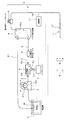
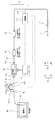
- FIG. 1 shows an embodiment of a liquid supply device 3 for supplying a low flow rate, low pressure liquid.
- This liquid supply device 3 has a supply flow path 2 for supplying a liquid containing microbubbles to a cleaning instrument 1 for cleaning a living body. Therefore, the cleaning device 1 and the liquid supply device 3 constitute a living body cleaning device S.
- the liquid supply apparatus 3 is an example suitable as an apparatus for supplying a liquid for washing intracranial hematoma in brain surgery.
- the microbubble means a bubble having a bubble diameter of 1 to 200 ⁇ m, and includes nanobubbles having a bubble diameter of less than 1 ⁇ m.
- the liquid supply device 3 in the illustrated example has a constant temperature bath 4 of sterile water (liquid) w, a tube pump 5 for feeding the sterile water w in the constant temperature bath 4 to the supply flow path 2, and for generating fine bubbles in the sterile water.
- a bubble circulation container 9 having a circulation path 21 to the thermostat 4, a cleaning tube pump 10 for supplying sterile water to the cleaning instrument 1, and a control unit 11.
- the thermostatic bath 4 is configured to be able to store sterile water w in a sterile state for a long time, and has a function capable of maintaining the sterile water w at a preferable temperature for living body cleaning (for example, around 37 ° C. of the standard body temperature).
- the tube pump 5 includes an elastic tube body 51 that also serves as the supply flow path 2 for the sterile water w, a rotation roller 52, and a rotation drive means (not shown) such as an electric motor.
- the tube body 51 is rotated while being sequentially crushed by this rotation, and the sterile water w in the tube body 51 is supplied to the downstream supply flow path 2. Thereby, it can send out by low flow volume and low pressure, maintaining the aseptic state of the aseptic water w.
- the water pressure is set to be 0.15 Mps and the flow rate is about 1 liter / min. Of course, more or less can be set.
- the air supply membrane module 6 is provided in the middle of the supply flow path 2 for generating fine bubbles in the liquid through the hollow fiber membrane, and is a compressor for supplying pressurized gas to the air supply membrane module 6 (Air supply means) 7 is provided.
- pressurized gas in addition to air, oxygen, carbon dioxide, nitrogen, ozone, or the like is used as necessary.
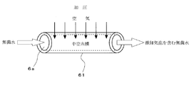
- FIG. 2 is a diagram for explaining the gas permeation function of the hollow fiber membrane 61.
- the hollow fiber membrane 61 by sending pressurized gas from the outside of the hollow fiber membrane 61 while flowing sterile water w into the hollow portion 6a of the hollow fiber membrane 61, the hollow fiber membrane 61 is formed in the film thickness direction. Through the fine structure, fine bubbles are generated in sterile water, thereby obtaining sterile water containing fine bubbles.
- a single porous membrane is generally used.
- a highly porous non-porous ultra-thin film is used as the porous layer.
- a three-layer composite hollow fiber membrane having a sandwiched structure is used.
- the highly selective permeable gas examples include carbon dioxide, nitrogen gas, ozone, oxygen and the like in addition to air as described above.
- the fine bubbles to be mixed are carbonated or washed.
- a method of using biologically inert nitrogen gas as a mixed gas or a method using ozone as a mixed gas to enhance the sterilizing effect of the cleaning site is also conceivable.
- vascular endothelial growth factor (VGEF) which is involved in angiogenesis and angiogenesis, is activated. It is also possible.
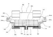
- FIG. 3 is a partial cross-sectional front view showing a specific structure of the air supply membrane module 6 using a plurality (several hundred) of the hollow fiber membranes 61 described above.
- This air supply membrane module 6 includes a plurality of hollow fiber membranes 61 having a hollow portion 6a through which sterile water w passes, and a pressurization for pressurizing gas into the sterile water in the hollow fiber membrane 61 from the outside of the hollow fiber membrane 61. And a pressure chamber 60.
- the air supply membrane module 6 includes a cylindrical case main body 62, joints 64, 64 disposed at both ends via O-rings 63, 63, and the joint 64 pressed against the main body 62. Sealing lids 65 and 65 for sealing are provided.
- the hollow fiber membrane 61 is all disposed in the case main body 62. Each hollow fiber membrane 61 is disposed along the length direction of the case main body 62, and one end side thereof communicates with the water supply space 66 and the other end side communicates with the drainage space 67.
- the aseptic water w supplied (press-fitted) from the water supply port 64a becomes aseptic water containing fine bubbles when passing through the hollow portion 6a of each hollow fiber membrane 61, and passes through the drain port 64c and the supply flow path 2. It is fed into the shear stress generating nozzle 8.
- the joint 64 on one end side having the water supply port 64a is provided with a male screw 64b for connecting the end joint 2a (see FIG. 1) of the tube tube constituting the supply flow path 2.
- the joint 64 on the other end side having the drain port 64c is provided with a male screw 64d for connecting an end joint 2b (see FIG. 1) of the tube tube constituting the supply flow path 2 to the shear stress generating nozzle 8. Yes.
- the case main body 62 of the air supply membrane module 6 is provided with an intake joint 68 connected to the joint 72 of the air supply pipe 71 of the compressor 7. All of these joints employ a screw coupling method.
- the hollow fiber membrane 61 is made of polyethylene
- the case body 62 is made of polycarbonate
- the O-ring is made of silicon.
- the material of the hollow fiber membrane may be hydrophobic, such as polypropylene, 4-methyl-1-pentene, etc., polyolefin, polyether, polymethyl methacrylate, polysulfone, polyacrylonitrile, fluororesin A system or the like can also be used.
- the case body can also be formed of other resin materials such as acetal or polypropylene, metal, or the like.
- the shear stress generating nozzle 8 is a nozzle that generates shear stress such as a Venturi tube or orifice (thinned flow path) for generating microbubbles or nanobubbles of bubbles smaller than fine bubbles, and an air supply membrane module 6 has a function of generating microbubbles when sterile water containing fine bubbles obtained through 6 passes through this nozzle.
- the bubble circulation container 9 is arranged at the rear stage of the shear stress generating nozzle 8.
- the bubble circulation container 9 is provided with a circulation path 21 for circulating aseptic water w containing microbubbles obtained through the shear stress generating nozzle 8 to the thermostatic bath 4.
- the thermostatic bath 4 passes through the circulation path 21. Designed to be circulated into
- a cleaning tube pump 10 for supplying aseptic water w containing microbubbles to the cleaning instrument 1 is disposed downstream of the bubble circulation container 9.
- the cleaning tube pump 10 is a small tube pump.
- the cleaning tube pump 10 has an inlet 10 a for liquid containing microbubbles in the bubble circulation container 9.
- the control unit 11 controls the operation state of the thermostatic bath 4, the tube pump 5, the compressor 7, and the cleaning tube pump 10 so as to discharge aseptic water containing microbubbles suitable for biological cleaning from the cleaning instrument 1.
- the liquid supply apparatus 3 is designed so that the aseptic water containing microbubbles has a particle size, a flow rate, a discharge pressure, and the like that do not damage the living tissue.
- a liquid containing fine bubbles having a particle size (bubble diameter) of about 1 ⁇ m to 200 ⁇ m can be generated.
- a liquid containing many 10 ⁇ m to 100 ⁇ m microbubbles can be generated. Designed.
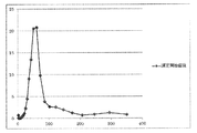
- FIG. 4 is a graph showing the particle size distribution measurement result of sterile water w containing microbubbles generated by the liquid supply device 3.
- the particle diameter described above is a particle diameter measured using the measurement principle of laser diffraction.
- a laser diffraction particle size distribution measuring device a laser diffraction particle size distribution measuring device HELOS & RODOS manufactured by Sympatec can be used.
- the cleaning instrument 1 controls the operation of a cylindrical part having a discharge hole for sterile water w containing microbubbles, a grip part formed in the cylindrical part, and the cleaning tube pump 10.
- Operation means (operation buttons) 17 are provided.
- the operation button 17 is connected to the control unit 11 by a signal line 18 indicated by a broken line in FIG.
- the tube pump 5 for feeding sterile water into the supply flow path 2 since the tube pump 5 for feeding sterile water into the supply flow path 2 is adopted, the sterile water can be fed into the supply flow path 2 at a low flow rate and low pressure suitable for living body cleaning, and the aseptic condition can be reduced. Aseptic water can be fed into the supply channel 2 while being held. Furthermore, by adopting the tube pump 5, it is possible to reliably prevent the backflow of liquid due to the back pressure of bubble water, the discharge of polluted gas, and the like.
- the microbubble generator B generates a microbubble in the liquid by passing a compressor 7 for supplying pressurized gas to the air supply membrane module 6 and a liquid containing fine bubbles via the air supply membrane module 6. Since the shear stress generating nozzle 8 is provided, microbubbles can be generated in sterile water flowing at a low flow rate and low pressure in the supply flow path 2. In addition, since the membrane used for the air supply membrane module 6 is air supply through a fine structure in both the porous membrane and the three-layer membrane, it prevents microbes from entering in the pressurized gas and supplies microscopic gas while supplying sterile gas. Bubbles can be generated.
- the sterile water containing microbubbles is used (washed). Regardless of whether or not, aseptic water containing microbubbles can be continuously produced to maintain its quality. Therefore, the sterile water containing the microbubbles can be used continuously or intermittently at any time as a living body washing liquid or the like during surgery.
- aseptic water w including microbubbles having a low flow rate and low pressure can be supplied and cleaned while being discharged from the discharge hole of the cleaning instrument 1, the living tissue is damaged. Without cleaning, the cleaning effect can be remarkably enhanced and cleaning can be performed quickly and cleanly. Further, by adopting the tube pump, it is possible to prevent the back flow of liquid and the discharge of pollutant gas due to the back pressure of bubble water.
- the cleaning instrument 1 with the operating means 17 for controlling the operation of the cleaning tube pump 10, the discharge amount of sterile water containing microbubbles at the time of surgery and the stoppage of the discharge from the discharge hole of the cleaning instrument 1, It is possible to easily and conveniently perform control such as discharge start.
- the circulation path 21 can be omitted and the bubble circulation container 9 can be used as a storage tank for sterile water containing microbubbles.
- FIG. 5 is a schematic configuration diagram showing Embodiment 2 of the liquid supply apparatus according to the present invention.
- components that are basically the same as those of the previous embodiment are denoted by the same reference numerals and description thereof is simplified.
- the liquid supply device S includes a thermostatic bath 4 of sterile water (liquid) w, a tube pump 5 that feeds the sterile water w in the thermostatic bath 4 into the supply channel 2, and An air supply membrane module 6 for generating aseptic fine bubbles in aseptic water, a compressor (air supply means) 7 for supplying pressurized gas to the air supply membrane module 6, and sterile water containing fine bubbles are allowed to pass through. And a shear stress generation type nozzle 8 for generating microbubbles, and a control unit 11 for them.
- the shear stress generating nozzle 8 is provided in two stages in series, and the second stage shear stress generating nozzle 8 is directly connected to the cleaning instrument 1 via the supply channel 2. It is what. Therefore, in this embodiment, the bubble circulation container 9, the circulation path 21, and the cleaning tube pump 10 are not provided.
- the bubble circulation container and the cleaning tube pump shown in the first embodiment are omitted.
- the living body cleaning apparatus including the control system can be further simplified.
- the example in which the shear stress generating nozzles 8 are arranged in two stages in series is shown, but two or more stages may be arranged as necessary. A plurality of stages may be arranged in parallel.
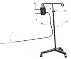
- FIG. 6 is a schematic configuration diagram of a main part showing Embodiment 3 of the liquid supply apparatus according to the present invention.
- components that are basically the same as those of the previous embodiment are denoted by the same reference numerals and description thereof is simplified.
- the liquid supply apparatus S has a configuration in which the bubble circulation container 9 is suspended and the sterile water w is naturally dropped by its own weight. That is, by using the suspending means 30, the bubble circulation container 9 is arranged at a position above the object to be cleaned such as a living body, and the natural fall tube 22 for liquid containing microbubbles extends from the bubble circulation container 9. It is the composition which has.
- the cleaning instrument 1 shown in FIG. 1 is connected to the distal end (free end) of the natural drop tube 22.
- the suspension means 30 It is preferable to set it as the structure provided with the height adjustment mechanism 31.
- the discharge pressure of the liquid containing a microbubble is made into the bubble. Adjustment is possible by simply changing the height position of the circulation container 9. Thereby, the discharge pressure of the liquid containing microbubbles can be set to a discharge pressure suitable for the object to be cleaned.
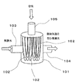
- the air supply membrane module 100 includes a hollow cylindrical housing 101, a number of hollow fiber membranes 102 disposed in the housing 101, an inlet 103 and a flow of sterile water w provided on the outer peripheral surface of the housing 101. An outlet 104 and a gas supply port 105 are provided. Therefore, the air supply membrane module 100 is configured to generate fine bubbles in sterile water by flowing sterile water into the housing 101 and press-fitting gas into the hollow portion of the hollow fiber membrane 102.
- the hollow fiber membranes 102 are bent in a U shape in the illustrated example, and are connected so that the opening portions at both ends communicate with the supply ports 105, respectively.
- the sterilized water w supplied from the inflow port 103 becomes aseptic water containing fine bubbles when flowing into and passing through the housing 101 and passes through the outflow port 104 and the supply flow path 2 to generate a shear stress generating nozzle. 8 is sent.
- the air supply membrane module itself can be further downsized.
Landscapes
- Chemical & Material Sciences (AREA)
- Chemical Kinetics & Catalysis (AREA)
- Health & Medical Sciences (AREA)
- Engineering & Computer Science (AREA)
- Heart & Thoracic Surgery (AREA)
- Biomedical Technology (AREA)
- Life Sciences & Earth Sciences (AREA)
- Animal Behavior & Ethology (AREA)
- General Health & Medical Sciences (AREA)
- Public Health (AREA)
- Veterinary Medicine (AREA)
- Hematology (AREA)
- Anesthesiology (AREA)
- Dispersion Chemistry (AREA)
- Nanotechnology (AREA)
- Cleaning By Liquid Or Steam (AREA)
- Surgical Instruments (AREA)
- Separation Using Semi-Permeable Membranes (AREA)
Priority Applications (2)
| Application Number | Priority Date | Filing Date | Title |
|---|---|---|---|
| US14/418,022 US20150190565A1 (en) | 2012-07-28 | 2013-07-24 | Liquid supply device and biological cleaning device |
| EP13826246.4A EP2881167A4 (en) | 2012-07-28 | 2013-07-24 | LIQUID SUPPLY DEVICE AND BIOLOGICAL CLEANING DEVICE |
Applications Claiming Priority (2)
| Application Number | Priority Date | Filing Date | Title |
|---|---|---|---|
| JP2012-167833 | 2012-07-28 | ||
| JP2012167833A JP6111029B2 (ja) | 2012-07-28 | 2012-07-28 | 液体供給装置及び生体洗浄装置 |
Publications (1)
| Publication Number | Publication Date |
|---|---|
| WO2014021165A1 true WO2014021165A1 (ja) | 2014-02-06 |
Family
ID=50027843
Family Applications (1)
| Application Number | Title | Priority Date | Filing Date |
|---|---|---|---|
| PCT/JP2013/070041 Ceased WO2014021165A1 (ja) | 2012-07-28 | 2013-07-24 | 液体供給装置及び生体洗浄装置 |
Country Status (4)
| Country | Link |
|---|---|
| US (1) | US20150190565A1 (enExample) |
| EP (1) | EP2881167A4 (enExample) |
| JP (1) | JP6111029B2 (enExample) |
| WO (1) | WO2014021165A1 (enExample) |
Cited By (1)
| Publication number | Priority date | Publication date | Assignee | Title |
|---|---|---|---|---|
| WO2019181765A1 (ja) * | 2018-03-20 | 2019-09-26 | 株式会社島津製作所 | ファインバブル供給装置及びファインバブル分析システム |
Families Citing this family (12)
| Publication number | Priority date | Publication date | Assignee | Title |
|---|---|---|---|---|
| CN105110551B (zh) * | 2015-06-16 | 2018-01-02 | 厦门绿邦膜技术有限公司 | 一种高溶氧曝气结合人工湿地的污水处理系统及处理工艺 |
| CN105036315B (zh) * | 2015-06-16 | 2018-06-26 | 厦门绿邦膜技术有限公司 | 一种曝气中空纤维膜组件及其连接结构 |
| WO2017091088A1 (en) * | 2015-11-23 | 2017-06-01 | The New Zealand Institute For Plant And Food Research Limited | Method and apparatus for releasing gas |
| US20170268118A1 (en) * | 2016-03-18 | 2017-09-21 | Kabushiki Kaisha Toshiba | Electrochemical reaction device |
| JP6981947B2 (ja) * | 2017-07-13 | 2021-12-17 | 環境技術サービス株式会社 | 気泡発生装置及び気泡発生方法 |
| JP6408083B1 (ja) * | 2017-07-13 | 2018-10-17 | 環境技術サービス株式会社 | 気泡発生装置及び気泡発生方法 |
| JP2021069997A (ja) * | 2019-10-31 | 2021-05-06 | キヤノン株式会社 | Ufb含有液作製装置、及びufb含有液作製方法 |
| CN111135368B (zh) * | 2020-02-29 | 2024-08-27 | 费蕾蕾 | 一种手术无菌液体自动取用仪 |
| JP2022078971A (ja) * | 2020-11-13 | 2022-05-25 | レネロファーマ株式会社 | 皮膚炎及び皮膚状態改善用オゾンバブリング装置及び皮膚炎及び皮膚状態改善方法 |
| EP4405019A4 (en) | 2021-09-23 | 2025-07-16 | Third Pole Inc | SYSTEMS AND METHODS FOR PROVIDING NITRIC OXIDE |
| US20230330359A1 (en) * | 2022-04-14 | 2023-10-19 | Third Pole, Inc. | Delivery of medicinal gas in a liquid medium |
| JP2023157155A (ja) * | 2022-04-14 | 2023-10-26 | ヤマト科学株式会社 | 洗浄水の製造システムおよび製造方法 |
Citations (11)
| Publication number | Priority date | Publication date | Assignee | Title |
|---|---|---|---|---|
| JPH08112587A (ja) * | 1994-10-17 | 1996-05-07 | F Tex:Kk | 微細気泡発生装置 |
| JP2001008854A (ja) * | 1999-04-28 | 2001-01-16 | Mitsubishi Rayon Co Ltd | 炭酸水洗浄器 |
| JP2004024926A (ja) * | 2002-05-09 | 2004-01-29 | Tatsuo Okazaki | 高濃度炭酸水による洗浄方法及び洗浄装置 |
| JP2004121962A (ja) | 2002-10-01 | 2004-04-22 | National Institute Of Advanced Industrial & Technology | ナノバブルの利用方法及び装置 |
| JP2005245817A (ja) * | 2004-03-05 | 2005-09-15 | National Institute Of Advanced Industrial & Technology | ナノバブルの製造方法 |
| JP2007167830A (ja) * | 2005-02-21 | 2007-07-05 | Eiji Matsumura | オゾン水生成装置、オゾン水生成方法及びオゾン水 |
| JP2008291521A (ja) | 2007-05-24 | 2008-12-04 | Sharp Corp | 肛門洗浄装置、及び肛門洗浄装置を具備する便器 |
| JP2009090214A (ja) * | 2007-10-09 | 2009-04-30 | Sato Jushi Kogyo Kk | 殺菌水製造装置 |
| JP2009286690A (ja) * | 2009-08-19 | 2009-12-10 | Human Empowerment Co Ltd | オゾン液変換装置、連通具および密閉容器 |
| JP2010005130A (ja) * | 2008-06-26 | 2010-01-14 | Shinwa:Kk | 医療用洗浄水供給装置 |
| JP2011206689A (ja) | 2010-03-30 | 2011-10-20 | Mie Univ | 微細気泡形成装置。 |
Family Cites Families (13)
| Publication number | Priority date | Publication date | Assignee | Title |
|---|---|---|---|---|
| JPS5933461Y2 (ja) * | 1980-11-17 | 1984-09-18 | 三菱レイヨン株式会社 | 飲料水への炭酸ガス溶解装置 |
| JPH02245230A (ja) * | 1989-03-17 | 1990-10-01 | Komatsu Ltd | 微細気泡発生方法 |
| JPH0312157A (ja) * | 1989-06-12 | 1991-01-21 | Komatsu Ltd | 浴槽用気泡発生装置 |
| JPH0377628A (ja) * | 1989-08-15 | 1991-04-03 | Komatsu Ltd | 中空糸モジュール |
| JPH06142153A (ja) * | 1992-05-21 | 1994-05-24 | Komatsu Kasei Kk | 浴槽用気泡発生装置 |
| JPH11139804A (ja) * | 1997-11-11 | 1999-05-25 | Dainippon Ink & Chem Inc | 超純水の比抵抗調整装置及び調整方法 |
| JP2000005586A (ja) * | 1998-06-24 | 2000-01-11 | Sony Corp | 純水の比抵抗値調整装置 |
| EP1254698B1 (en) * | 2000-01-12 | 2010-09-08 | Sekisui Chemical Co., Ltd. | Ozone treating apparatus |
| JP2002028462A (ja) * | 2000-01-12 | 2002-01-29 | Sekisui Chem Co Ltd | オゾン処理装置 |
| US6905111B2 (en) * | 2000-04-18 | 2005-06-14 | Mitsubishi Rayon Engineering Co., Ltd. | Apparatus and method for producing aqueous carbonic acid solution |
| JP2001293344A (ja) * | 2000-04-18 | 2001-10-23 | Mitsubishi Rayon Eng Co Ltd | 炭酸水製造装置および炭酸水製造方法 |
| JP2007228936A (ja) * | 2006-03-03 | 2007-09-13 | Hiroshima Kasei Ltd | 哺乳動物の皮膚を洗浄する方法および哺乳動物の皮膚洗浄システム |
| PH12013500732A1 (en) * | 2010-09-30 | 2019-10-11 | Dfb Tech Ltd | Device for disinfecting and/or rinsing endoscopes with limited escape of fumes |
-
2012
- 2012-07-28 JP JP2012167833A patent/JP6111029B2/ja active Active
-
2013
- 2013-07-24 US US14/418,022 patent/US20150190565A1/en not_active Abandoned
- 2013-07-24 EP EP13826246.4A patent/EP2881167A4/en not_active Withdrawn
- 2013-07-24 WO PCT/JP2013/070041 patent/WO2014021165A1/ja not_active Ceased
Patent Citations (11)
| Publication number | Priority date | Publication date | Assignee | Title |
|---|---|---|---|---|
| JPH08112587A (ja) * | 1994-10-17 | 1996-05-07 | F Tex:Kk | 微細気泡発生装置 |
| JP2001008854A (ja) * | 1999-04-28 | 2001-01-16 | Mitsubishi Rayon Co Ltd | 炭酸水洗浄器 |
| JP2004024926A (ja) * | 2002-05-09 | 2004-01-29 | Tatsuo Okazaki | 高濃度炭酸水による洗浄方法及び洗浄装置 |
| JP2004121962A (ja) | 2002-10-01 | 2004-04-22 | National Institute Of Advanced Industrial & Technology | ナノバブルの利用方法及び装置 |
| JP2005245817A (ja) * | 2004-03-05 | 2005-09-15 | National Institute Of Advanced Industrial & Technology | ナノバブルの製造方法 |
| JP2007167830A (ja) * | 2005-02-21 | 2007-07-05 | Eiji Matsumura | オゾン水生成装置、オゾン水生成方法及びオゾン水 |
| JP2008291521A (ja) | 2007-05-24 | 2008-12-04 | Sharp Corp | 肛門洗浄装置、及び肛門洗浄装置を具備する便器 |
| JP2009090214A (ja) * | 2007-10-09 | 2009-04-30 | Sato Jushi Kogyo Kk | 殺菌水製造装置 |
| JP2010005130A (ja) * | 2008-06-26 | 2010-01-14 | Shinwa:Kk | 医療用洗浄水供給装置 |
| JP2009286690A (ja) * | 2009-08-19 | 2009-12-10 | Human Empowerment Co Ltd | オゾン液変換装置、連通具および密閉容器 |
| JP2011206689A (ja) | 2010-03-30 | 2011-10-20 | Mie Univ | 微細気泡形成装置。 |
Non-Patent Citations (1)
| Title |
|---|
| See also references of EP2881167A4 |
Cited By (6)
| Publication number | Priority date | Publication date | Assignee | Title |
|---|---|---|---|---|
| WO2019181765A1 (ja) * | 2018-03-20 | 2019-09-26 | 株式会社島津製作所 | ファインバブル供給装置及びファインバブル分析システム |
| CN111417457A (zh) * | 2018-03-20 | 2020-07-14 | 株式会社岛津制作所 | 小气泡供给装置以及小气泡分析系统 |
| JPWO2019181765A1 (ja) * | 2018-03-20 | 2020-12-03 | 株式会社島津製作所 | ファインバブル供給装置及びファインバブル分析システム |
| JP2022188187A (ja) * | 2018-03-20 | 2022-12-20 | 株式会社島津製作所 | ファインバブル供給装置及びファインバブル分析システム |
| JP7352913B2 (ja) | 2018-03-20 | 2023-09-29 | 株式会社島津製作所 | ファインバブル供給装置及びファインバブル分析システム |
| US12161980B2 (en) | 2018-03-20 | 2024-12-10 | Shimadzu Corporation | Fine bubble supply device, and fine bubble analyzing system |
Also Published As
| Publication number | Publication date |
|---|---|
| JP6111029B2 (ja) | 2017-04-05 |
| JP2014024039A (ja) | 2014-02-06 |
| EP2881167A1 (en) | 2015-06-10 |
| US20150190565A1 (en) | 2015-07-09 |
| EP2881167A4 (en) | 2016-06-08 |
Similar Documents
| Publication | Publication Date | Title |
|---|---|---|
| JP6111029B2 (ja) | 液体供給装置及び生体洗浄装置 | |
| US8083861B2 (en) | Apparatus and method for cleaning pipelines, tubing and membranes using two-phase flow | |
| JP5869038B2 (ja) | 膜接触装置による液体の脱ガス | |
| JP4477810B2 (ja) | ガスと液体との混合相流を用いた通路の洗浄方法 | |
| JP2007534454A5 (enExample) | ||
| KR101188635B1 (ko) | 관로 장착형의 다공성 나노 필름 멤브레인 벤튜리 튜브를 이용한 다용도 나노 버블수 발생장치 | |
| US8192620B2 (en) | Ballast water treating apparatus | |
| US20090273103A1 (en) | Nanofluid Production Apparatus and Method | |
| GB2563212A (en) | Cleaning, healing and regeneration of tissue and wounds | |
| JP2006167612A (ja) | マイクロバブル発生装置 | |
| JP2008290011A (ja) | 微細気泡発生装置 | |
| JP4215131B2 (ja) | フィルタの洗浄および浄化システム | |
| JP5006273B2 (ja) | マイクロバブル発生装置 | |
| JP2012176396A (ja) | 膜分離活性汚泥装置 | |
| JP2018149506A (ja) | マイクロバブル発生装置 | |
| JP4922045B2 (ja) | 微細気泡発生方法及び微細気泡発生装置 | |
| KR102527492B1 (ko) | 녹조 방지 양액 순환 시스템 및 방법 | |
| JP2012206025A (ja) | バラスト水製造装置およびその運転方法 | |
| JP6617071B2 (ja) | 純水製造方法及び装置 | |
| JP6010273B1 (ja) | 内視鏡リプロセッサ | |
| JP2007061697A (ja) | 分離膜の洗浄方法、ならびに有機性汚水処理装置 | |
| JP5743096B2 (ja) | 膜分離活性汚泥装置 | |
| KR101340961B1 (ko) | 회전식 미세 기포 발생장치 | |
| JP2001293344A (ja) | 炭酸水製造装置および炭酸水製造方法 | |
| KR102799348B1 (ko) | 버블 생성 장치 및 이를 이용한 선박 평형수 처리 시스템 |
Legal Events
| Date | Code | Title | Description |
|---|---|---|---|
| 121 | Ep: the epo has been informed by wipo that ep was designated in this application |
Ref document number: 13826246 Country of ref document: EP Kind code of ref document: A1 |
|
| NENP | Non-entry into the national phase |
Ref country code: DE |
|
| WWE | Wipo information: entry into national phase |
Ref document number: 14418022 Country of ref document: US |
|
| WWE | Wipo information: entry into national phase |
Ref document number: 2013826246 Country of ref document: EP |