WO2014021091A1 - ナット部材 - Google Patents
ナット部材 Download PDFInfo
- Publication number
- WO2014021091A1 WO2014021091A1 PCT/JP2013/069255 JP2013069255W WO2014021091A1 WO 2014021091 A1 WO2014021091 A1 WO 2014021091A1 JP 2013069255 W JP2013069255 W JP 2013069255W WO 2014021091 A1 WO2014021091 A1 WO 2014021091A1
- Authority
- WO
- WIPO (PCT)
- Prior art keywords
- screw
- nut member
- fitting
- aiming
- female screw
- Prior art date
- Legal status (The legal status is an assumption and is not a legal conclusion. Google has not performed a legal analysis and makes no representation as to the accuracy of the status listed.)
- Ceased
Links
Images



Classifications
-
- F—MECHANICAL ENGINEERING; LIGHTING; HEATING; WEAPONS; BLASTING
- F16—ENGINEERING ELEMENTS AND UNITS; GENERAL MEASURES FOR PRODUCING AND MAINTAINING EFFECTIVE FUNCTIONING OF MACHINES OR INSTALLATIONS; THERMAL INSULATION IN GENERAL
- F16B—DEVICES FOR FASTENING OR SECURING CONSTRUCTIONAL ELEMENTS OR MACHINE PARTS TOGETHER, e.g. NAILS, BOLTS, CIRCLIPS, CLAMPS, CLIPS OR WEDGES; JOINTS OR JOINTING
- F16B37/00—Nuts or like thread-engaging members
- F16B37/04—Devices for fastening nuts to surfaces, e.g. sheets, plates
-
- B—PERFORMING OPERATIONS; TRANSPORTING
- B60—VEHICLES IN GENERAL
- B60Q—ARRANGEMENT OF SIGNALLING OR LIGHTING DEVICES, THE MOUNTING OR SUPPORTING THEREOF OR CIRCUITS THEREFOR, FOR VEHICLES IN GENERAL
- B60Q1/00—Arrangement of optical signalling or lighting devices, the mounting or supporting thereof or circuits therefor
- B60Q1/02—Arrangement of optical signalling or lighting devices, the mounting or supporting thereof or circuits therefor the devices being primarily intended to illuminate the way ahead or to illuminate other areas of way or environments
- B60Q1/04—Arrangement of optical signalling or lighting devices, the mounting or supporting thereof or circuits therefor the devices being primarily intended to illuminate the way ahead or to illuminate other areas of way or environments the devices being headlights
- B60Q1/06—Arrangement of optical signalling or lighting devices, the mounting or supporting thereof or circuits therefor the devices being primarily intended to illuminate the way ahead or to illuminate other areas of way or environments the devices being headlights adjustable, e.g. remotely-controlled from inside vehicle
- B60Q1/068—Arrangement of optical signalling or lighting devices, the mounting or supporting thereof or circuits therefor the devices being primarily intended to illuminate the way ahead or to illuminate other areas of way or environments the devices being headlights adjustable, e.g. remotely-controlled from inside vehicle by mechanical means
- B60Q1/0683—Adjustable by rotation of a screw
-
- F—MECHANICAL ENGINEERING; LIGHTING; HEATING; WEAPONS; BLASTING
- F16—ENGINEERING ELEMENTS AND UNITS; GENERAL MEASURES FOR PRODUCING AND MAINTAINING EFFECTIVE FUNCTIONING OF MACHINES OR INSTALLATIONS; THERMAL INSULATION IN GENERAL
- F16B—DEVICES FOR FASTENING OR SECURING CONSTRUCTIONAL ELEMENTS OR MACHINE PARTS TOGETHER, e.g. NAILS, BOLTS, CIRCLIPS, CLAMPS, CLIPS OR WEDGES; JOINTS OR JOINTING
- F16B37/00—Nuts or like thread-engaging members
- F16B37/005—Nuts or like thread-engaging members into which threads are cut during screwing
-
- F—MECHANICAL ENGINEERING; LIGHTING; HEATING; WEAPONS; BLASTING
- F16—ENGINEERING ELEMENTS AND UNITS; GENERAL MEASURES FOR PRODUCING AND MAINTAINING EFFECTIVE FUNCTIONING OF MACHINES OR INSTALLATIONS; THERMAL INSULATION IN GENERAL
- F16B—DEVICES FOR FASTENING OR SECURING CONSTRUCTIONAL ELEMENTS OR MACHINE PARTS TOGETHER, e.g. NAILS, BOLTS, CIRCLIPS, CLAMPS, CLIPS OR WEDGES; JOINTS OR JOINTING
- F16B37/00—Nuts or like thread-engaging members
- F16B37/04—Devices for fastening nuts to surfaces, e.g. sheets, plates
- F16B37/041—Releasable devices
- F16B37/043—Releasable devices with snap action
-
- B—PERFORMING OPERATIONS; TRANSPORTING
- B60—VEHICLES IN GENERAL
- B60Q—ARRANGEMENT OF SIGNALLING OR LIGHTING DEVICES, THE MOUNTING OR SUPPORTING THEREOF OR CIRCUITS THEREFOR, FOR VEHICLES IN GENERAL
- B60Q2200/00—Special features or arrangements of vehicle headlamps
- B60Q2200/30—Special arrangements for adjusting headlamps, e.g. means for transmitting the movements for adjusting the lamps
- B60Q2200/32—Ball-joints
-
- F—MECHANICAL ENGINEERING; LIGHTING; HEATING; WEAPONS; BLASTING
- F16—ENGINEERING ELEMENTS AND UNITS; GENERAL MEASURES FOR PRODUCING AND MAINTAINING EFFECTIVE FUNCTIONING OF MACHINES OR INSTALLATIONS; THERMAL INSULATION IN GENERAL
- F16B—DEVICES FOR FASTENING OR SECURING CONSTRUCTIONAL ELEMENTS OR MACHINE PARTS TOGETHER, e.g. NAILS, BOLTS, CIRCLIPS, CLAMPS, CLIPS OR WEDGES; JOINTS OR JOINTING
- F16B33/00—Features common to bolt and nut
- F16B33/002—Means for preventing rotation of screw-threaded elements
-
- F—MECHANICAL ENGINEERING; LIGHTING; HEATING; WEAPONS; BLASTING
- F16—ENGINEERING ELEMENTS AND UNITS; GENERAL MEASURES FOR PRODUCING AND MAINTAINING EFFECTIVE FUNCTIONING OF MACHINES OR INSTALLATIONS; THERMAL INSULATION IN GENERAL
- F16B—DEVICES FOR FASTENING OR SECURING CONSTRUCTIONAL ELEMENTS OR MACHINE PARTS TOGETHER, e.g. NAILS, BOLTS, CIRCLIPS, CLAMPS, CLIPS OR WEDGES; JOINTS OR JOINTING
- F16B33/00—Features common to bolt and nut
- F16B33/006—Non-metallic fasteners using screw-thread
-
- F—MECHANICAL ENGINEERING; LIGHTING; HEATING; WEAPONS; BLASTING
- F16—ENGINEERING ELEMENTS AND UNITS; GENERAL MEASURES FOR PRODUCING AND MAINTAINING EFFECTIVE FUNCTIONING OF MACHINES OR INSTALLATIONS; THERMAL INSULATION IN GENERAL
- F16H—GEARING
- F16H25/00—Gearings comprising primarily only cams, cam-followers and screw-and-nut mechanisms
- F16H25/18—Gearings comprising primarily only cams, cam-followers and screw-and-nut mechanisms for conveying or interconverting oscillating or reciprocating motions
- F16H25/20—Screw mechanisms
- F16H25/24—Elements essential to such mechanisms, e.g. screws, nuts
- F16H2025/2445—Supports or other means for compensating misalignment or offset between screw and nut
Definitions
- the present invention relates to a nut member suitable for use in an aiming mechanism for adjusting the optical axis direction of a lamp.
- a lamp such as a headlamp of an automobile is provided with an aiming mechanism for adjusting a lamp optical axis direction as a reference of a light irradiation direction, and an aiming screw and an aiming nut are provided as main components of the aiming mechanism.
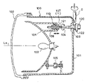
- FIG. 6 shows a conceptual configuration of the aiming mechanism. As shown in FIG. 6, a reflector 104 that supports a light source (light bulb or LED) 103 is supported in a lamp housing 100 including a lamp body 101 and a front cover 102 so as to be tiltable in the vertical direction and the horizontal direction. Aiming adjustment is performed by adjusting the tilt angle of the reflector 104 in the vertical direction and the horizontal direction.
- a fulcrum part 105 having a ball joint structure is disposed at one place behind the reflector 104, and the fulcrum part 105 is arranged in a vertical direction at a place different from the fulcrum part 105, respectively.
- an aiming unit 106 for adjusting the horizontal direction is illustrated.
- the aiming screw 120 is rotatably held on the lamp body 101, and the bracket 109 of the reflector 104 is attached to the male screw portion 121 of the aiming screw 120.
- the aiming nut 107 supported by the screw is screwed together.
- the aiming screw 120 By rotating the aiming screw 120, the aiming nut 107 is screwed in the front-rear direction, and the reflector 104 is tilted in the vertical direction and the left-right direction with the fulcrum portion 105 as a fulcrum by the movement accompanying the screwing.
- the aiming nut 107 a nut member called a so-called self-locking nut may be used.
- the self-locking nut of Patent Document 1 has a pair of legs that are elastic in the radial direction, and the legs are fitted into fitting holes that are opened in the bracket 109 of the reflector 104 as shown in FIG. 110 and is supported by the bracket 109.
- the inner peripheral surface of the shaft hole of the self-locking nut is configured as a female screw portion, and is screwed into the male screw portion 121 of the aiming screw 120 as described above.
- This female threaded portion is configured as a circumferential surface before the aiming screw is screwed together, but by inserting the aiming screw into the shaft hole in a press-fitted state while rotating the aiming screw, the inner peripheral surface of the shaft hole is aiming. It is shaved by a male screw portion of the screw and formed as a female screw.
- the self-locking nut of Patent Document 1 (hereinafter simply referred to as a nut member) has a configuration in which a female screw portion and a fitting portion overlap each other in the axial direction of the nut member. That is, the fitting part is provided in the outer peripheral position of the female screw part. Therefore, when an aiming screw (hereinafter simply referred to as a screw) is inserted into the nut member in a press-fitted state and screwed, the inner peripheral surface of the shaft hole of the female screw portion swells in the outer diameter direction by the screw, and this swell As a result, the outer diameter of the fitting portion is increased, and there is no dimensional margin set between the fitting hole and the fitting hole of the bracket.
- a aiming screw hereinafter simply referred to as a screw
- the thickness dimension of the radial direction in the internal thread part and the fitting part of the outer periphery is designed more than a required dimension in order to ensure the required mechanical strength in a nut member. .
- “sink marks” easily occur on the inner peripheral surface of the female screw part or the outer peripheral surface of the fitting part, and the dimensional accuracy of the female screw part and the fitting part is caused by this “sink”. Decreases, and this affects the operability of aiming adjustment when the screw is screwed.
- the nut member of Patent Document 1 is merely provided with a shaft hole for forming a female screw portion on the surface on the side where the screw is inserted, the tip of the screw is attached to the shaft of the nut member.
- Work to insert into the hole becomes difficult.
- the reflector posture is often not oriented in a predetermined direction with high accuracy. Therefore, it becomes difficult to insert the screw into the nut member by positioning the axial hole direction of the nut member and the axial center direction of the screw on the same straight line, and workability when assembling the aiming mechanism is deteriorated.
- An object of the present invention is to provide a nut member capable of improving the operability of aiming adjustment. Another object of the present invention is to provide a nut member capable of improving workability when assembling the aiming mechanism.
- the present invention is a nut member comprising a fitting portion that is fitted in a fitting hole provided in an object, and a female screw portion that is screwed into a male screw portion of the screw after being inserted into the screw.
- the fitting portion and the female screw portion are formed at different positions in the axial direction of the nut member.
- This screw is configured as an aiming screw supported by a fixed member such as a lamp housing of the lamp so as to be rotatable, and the nut member is configured as an aiming nut supported by a tilting member such as a reflector of the lamp.
- the fitting portion has a fitting groove to be fitted into the fitting hole, and a cavity is provided inside the groove bottom surface of the fitting groove.
- an introduction portion having an inverted conical surface for guiding the tip of the screw is provided at an end portion of the female screw portion on the side where the screw is inserted.
- the female screw part and the fitting part are in a position offset in the axial direction of the nut member, when the screw is screwed, the female screw part swells in the outer direction to screw the screw. The operating force when doing so will not be excessive. On the other hand, even if the female screw portion swells in the outer direction, the bulge does not affect the fitting portion, and the fitting state of the fitting portion in the fitting hole can be stably maintained. it can. Thereby, when the nut member is applied to the aiming mechanism, the operability of the axial rotation of the screw can be improved, and the tilting of the object such as the reflector accompanying the movement of the nut member can be performed smoothly. The operability of aiming adjustment can be improved.
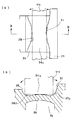
- FIG. 6 is a plan view of a fitting groove of a nut member and a cross-sectional view taken along line BB. It is a schematic sectional drawing of a lamp
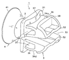
- FIG. 1 is an external perspective view of a form in which the present invention is configured as a self-locking nut
- FIG. 2 is an external perspective view of the self-locking nut (hereinafter referred to as a nut member) 1 as viewed from the opposite side.
- the nut member 1 corresponds to the aiming nut 107 shown in FIG.
- the nut member 1 is fitted and supported in a fitting hole 110 opened in a bracket 109 of a reflector 104 (an object, an example of a tilting member) housed in the lamp housing 100, and the lamp body 101 of the lamp housing 100.
- a screw 120 that is rotatably supported by (an example of a fixing member).
- the screw 120 is axially rotated in the gear portion 122 exposed to the outside of the lamp housing, the nut member 1 is moved in the axial direction of the screw 120.
- the nut member 1 tilts the reflector 104 in the front-rear direction or the horizontal direction of the lamp with the fulcrum portion 105 as the fulcrum via the bracket 109 to adjust the aiming of the optical axis Lx of the lamp.
- FIG. 3 shows an axial longitudinal sectional view of a form in which the upper and lower aiming portions 106 shown in FIG. 6 are configured by the screw 120 and the nut member 1.
- the screw 120 has a support portion 123 that is inserted into a cylindrical support hole 108 provided in the lamp body 101.
- a male screw portion 121 is formed over a portion on the front end side of the support portion 123, and a gear portion 122 for rotating the shaft is exposed to a portion exposed to the outside of the lamp body 101 on the rear end side of the support portion 123. Is formed.
- the screw 120 is provided with a pair of blade-like elastic locking pieces 124 whose diameter is increased rearward at the front end portion of the support portion 123.
- the rear end portion of the elastic locking piece 124 is elastically engaged with the inner edge of the support hole 108, so that the support portion 123 is in the support hole 108. It is locked to.
- FIG. 4 is a longitudinal sectional view of the nut member 1 in the axial direction.
- the nut member 1 includes a female screw portion 2 formed as a female screw into which the male screw portion 121 of the screw 120 is screwed, and the nut member 1 provided on a bracket 109 of the reflector 104.
- a fitting portion 3 for fitting into the fitting hole 110 and supporting the bracket 109 is provided.
- an introduction portion 4 for introducing the tip of the screw 120 into the female screw portion 2 is provided.
- Each part of the female screw part 2, the fitting part 3, and the introduction part 4 is integrally formed of a resin material.
- the vertical direction and the horizontal direction are based on FIG. 3 and FIG.
- the female screw portion 2 is formed in a partial region in the axial direction of the nut member 1 and is formed in a short cylindrical shape having a shaft hole 21 into which the screw 120 can be inserted from the front end side.
- the cylindrical inner peripheral surface 22 of the shaft hole 21 is formed with a plurality of, here four, grooves 23 that are equally distributed in the circumferential direction and extend in the axial direction.
- the inner peripheral surface 22 is configured as an inner peripheral surface divided in the circumferential direction.
- the groove 23 reduces the contact resistance with the inner peripheral surface 22 when the screw 120 is inserted, facilitates the insertion of the screw 120, and facilitates the axial rotation of the screw 120 when forming the female screw. It is provided to make it.
- the introduction portion 4 is formed in a trumpet shape that protrudes along the axial direction from one end on the right side of the female screw portion 2 and protrudes so that the protruding tip side continuously expands in diameter, that is, an inverted conical shape.
- the cone apex angle of the introduction portion 4 formed in the inverted conical shape is set as large as possible within a range in which the outer dimension of the nut member 1 does not become excessive.
- the cone apex angle of the introduction part 4 is set to an angle of 80 degrees to 90 degrees.
- the outer diameter of the circular tip edge 41 on the protruding tip side of the introduction portion 4 is as large as possible within the range in which the outer dimension of the nut member 1 is not excessive, and at least the outer dimension of the fitting portion 3. Larger diameter dimension is set.
- the outer diameter dimension of the tip edge 41 is set to about four times the inner diameter dimension of the female screw portion 2, in other words, about four times the outer diameter size of the male screw portion 121 of the screw 120. ing.
- the reverse conical surface is smoothly continuous with the inner peripheral surface 22 of the female screw portion 2. It is configured.
- the conical surface constituting the introduction portion 4 may be a pyramid surface.
- the fitting portion 3 is formed at the other end portion on the left side of the female screw portion 2 in the axial direction.
- the fitting portion 3 includes a flange 31 provided at the other end position of the female screw portion 2 and a pair extending in the axial direction toward the other end with the flange 31 as a base end portion and facing vertically.
- the leg piece 32 is provided.
- the flange 31 is a rectangular plate close to a square having an outer dimension larger than the opening dimension of the fitting hole 110 in order to prevent the flange 31 from dropping from the fitting hole 110 provided in the bracket 109, as will be described later. It is formed as. Further, the shaft hole 21 of the female screw portion 2 is penetrated through the central portion of the flange 31 so that the screw 120 can be inserted.
- the pair of leg pieces 32 are opposed to each other in the vertical direction by a wedge-shaped notch 33 formed in the axial direction from the other end side of the nut member 1. These leg pieces 32 are connected to the flange 31 at the base end portion directed to the right side, and each leg piece 32 is configured to be elastically deformable in the vertical direction with the base end portion as a fulcrum. . These leg pieces 32 have an outer shape substantially the same as the shape of the fitting hole 110 opened in the bracket 109 when viewed from the axial direction of the nut member 1, and the opening dimension of the fitting hole 110 in the vertical direction. It is formed to have a slightly larger external dimension.
- each leg piece 32 has the tip of the notch 33 reaching the shaft hole 21 of the female screw portion 2, so that when each of the leg pieces 32 is elastically deformed inwardly, the inner peripheral surface 22 of the female screw portion 2. A part of the other end side is narrowed to exhibit a self-locking function.
- fitting grooves 34u and 34d (hereinafter referred to as upper and lower fittings) that are recessed in the required depth toward the inner side. Grooves are sometimes collectively referred to by reference numeral 34).
- These fitting grooves 34u, 34d are portions shifted in the other end direction on the left side with respect to the female screw portion 2, in other words, portions offset with respect to the female screw portion 2 on the opposite side in the axial direction from the introduction portion 4. Is formed.
- it is offset by a dimension ⁇ .
- the upper fitting groove 34u has the thickness of the bracket 109 constituting the inner edge 111 of the fitting hole 110 of the bracket 109 in the axial direction of the nut member 1. It is formed with approximately equal dimensions.
- the lower fitting groove 34d is formed to have a size slightly larger than the upper fitting groove 34u, and is formed over the entire width of the nut member 1 in a direction orthogonal to the axial direction of the nut member 1.
- Each leg piece 32 is formed with a cavity 35 penetrating in the width direction in a region inside the groove bottom surface of the fitting groove 34. By this cavity 35, the inner bottom surface of the fitting groove 34 is configured as a plate-like fitting plate portion 36 having elasticity in the plate thickness direction.
- the cavity 35 in this way, the volume of the resin in each leg piece 32 can be reduced, and the occurrence of “sinking” in the fitting portion 3 when the nut member 1 is resin-molded is suppressed.
- a nut member with high dimensional accuracy can be formed.
- 5 (a) and 5 (b) are a plan view of the fitting groove 34u (34) of the nut member 1 and a sectional view taken along the line BB.
- the fitting plate portion 36 has a cross-sectional shape that is curved so that the central portion of the nut member 1 in the axial direction swells somewhat outward.
- the fitting plate portion 36 is formed as a part of a cylindrical surface obtained by extending an arc surface centering on a part on the axis of the nut member 1 in the width direction.
- the fitting groove 34 is formed by a fitting plate portion 36 and a pair of standing wall portions 37 and 38 facing in the axial direction. As shown in FIG.
- the fitting groove 34 is formed in a drum shape in which the dimension in the axial direction is narrow in the center part in the width direction and the dimension in both side parts in the width direction is larger than that in the center part. Yes.
- the dimension of the central portion is different in the upper and lower fitting grooves 34, but the upper fitting groove 34u is substantially the same as the thickness of the inner edge 111 of the fitting hole 110.
- the connecting surface portions 37a and 38a, to which the fitting plate portion 36 and the standing wall portions 37 and 38 are connected, are formed in a curved shape having a gentle cross-sectional shape in the axial direction. These connecting surface portions 37a and 38a are particularly preferably provided in the upper fitting groove 34u.
- the fitting groove 34 of the leg piece 32 is fitted into the inner edge 111 of the fitting hole 110.
- the leg piece 32 is elastically deformed inward with the base end portion as a fulcrum, and is inserted through the inner edge portion 111 of the fitting hole 110.
- the leg piece 32 is fitted to the inner edge 111 by elastically returning to the outside after insertion, and is held by the bracket 109 by the elastic return force.
- the fitting plate portion 36 of the fitting groove 34 can be elastically deformed in the radial direction by the cavity 35, the fitting plate portion 36 has an elastic force due to the elastic deformation to the inner edge portion 111 of the fitting hole 110. It will abut. Therefore, even when a slight dimensional error occurs between the fitting hole 110 and the fitting groove 34, a suitable fitting state can be secured, and the nut member 1 is held in the fitting hole 110 in a stable state. be able to.
- the tip of the screw 120 inserted from the rear of the lamp housing 100 is connected to the shaft hole of the female screw portion 2 of the nut member 1. Interpolate to 21.
- the introduction portion 4 provided on one end side of the nut member 1 is formed in an inverted conical shape, the tip of the screw 120 is brought into contact with the inner surface of the introduction portion 4 as the screw 120 is inserted. The process proceeds while being guided by the inverted conical shape of the inner surface. As a result, the tip of the screw 120 is guided toward the center position of the nut member 1 and guided to the shaft hole 21 of the female screw portion 2.
- the tip of the screw 120 is moved.
- the screw 120 can be reliably guided to the shaft hole 21 of the female screw portion 2 and can be inserted into the female screw portion 2.
- the male screw portion 121 of the screw 120 enters the female screw portion 2 of the nut member 1.
- the male screw portion 121 is advanced while forming a female screw on the inner peripheral surface 22 of the female screw portion 2.
- the male screw portion 121 of the screw 120 is screwed into the female screw portion 2 of the nut member 1, and the assembly of the aiming portion is completed.
- the male screw part 121 of the screw 120 is screwed into the female screw part 2 of the nut member 1, the male screw part 121 is inserted into the female screw part 2 in a press-fitted state. Therefore, the female thread portion 2 of the nut member 1 is deformed so as to swell in the outer diameter direction, and the outer diameter dimension of the female thread portion 2 is somewhat increased.
- the female screw portion 2 is in a position offset in the axial direction from the fitting portion 3, particularly the fitting groove 34, the fitting plate portion 36 is fitted even when the outer diameter of the female screw portion 2 increases. There will be no increase in the force of contact with the inner edge 111 of the joint hole 110. In other words, when the screw 120 is inserted, the female screw portion 2 can freely swell in the outer diameter direction, and the operating force when inserting the screw 120 does not become excessive.
- the female screw portion 2 and the fitting groove 34 are offset in the axial direction in this way, even if the screw 120 is inserted into the nut member 1 and the outer diameter size of the female screw portion 2 is increased, The contact force between the inner edge portion 111 of the fitting hole 110 and the fitting plate portion 36 does not increase. Therefore, the degree of freedom of relative movement between the fitting hole 110 and the fitting groove 34 is ensured.
- the pair of leg pieces 32 is elastically pressed inward by the fitting of the fitting hole 110 and the fitting groove 34, the shaft hole of the female screw portion 2 is formed at the base end portion of the leg piece 32. Dimensions are reduced. Thereby, the internal thread part 2 is pressed to the internal thread direction with respect to the external thread part 121 of the screw 120, and the self-locking function is exhibited.
- the screwing position of the female screw portion 2 of the nut member 1 with respect to the male screw portion 121 is changed, and accordingly, the nut member 1 moves in the axial direction with respect to the screw 120.
- the bracket 109 that is, the reflector 104 is tilted with the fulcrum portion 105 as a fulcrum.
- the nut member 1 is linearly moved in the direction along the axial direction of the screw 120, and the reflector 104 is moved in the arc direction around the fulcrum portion 105, so that a minute relative movement can be performed between the two. It is necessary to.
- the fitting plate portion 36 of the fitting groove 34 of the nut member 1 is fitted to the inner edge portion 111 of the fitting hole 110 with an elastic force by the cavity 35. Therefore, the nut member 1 is relatively moved in the plate thickness direction of the fitting plate portion 36 in the fitting hole 110, and relative movement in the plate thickness direction, that is, the vertical direction is allowed. Further, the fitting plate portion 36 that is in contact with the inner edge portion 111 of the fitting hole 110 is formed in a cylindrical surface. Therefore, the nut member 1 is relatively tilted in the circular arc direction of the cylindrical surface in the fitting hole 110, and relative tilting in the vertical direction, that is, the tilting direction of the reflector 104 is allowed.
- the nut member 1 can be tilted relative to the inner edge 111 of the fitting hole 110 in the planar direction of the fitting groove 34. Yes, relative tilting in the horizontal direction indicated by arrows in the plane direction, that is, FIG. 5A is allowed.
- the fitting groove 34 has a drum shape with a narrow center in the width direction, even when the nut member 1 is tilted relative to the fitting hole 110 in the horizontal direction, the inner edge portion 111 of the fitting hole 110 is The fitting groove 34 tilts relative to the center in the width direction as a fulcrum. Therefore, the relative position between the nut member 1 and the fitting hole 110 in the axial direction of the screw 120 is kept constant.
- the gentle curves provided at both ends of the fitting plate portion 36 even if the contact position between the inner edge 111 of the fitting hole 110 and the fitting plate portion 36 changes, as shown in FIG. 5B, the gentle curves provided at both ends of the fitting plate portion 36.
- the inner edge portion 111 of the fitting hole 110 is slidably brought into contact with the shaped connecting surface portions 37a and 38a. Therefore, a smooth relative tilt between them, that is, a relative tilt in the vertical direction of the nut member 1 can be ensured as shown by an arrow in FIG.
- the lower fitting groove 34d has a width dimension larger than that of the inner edge portion 111, so that the inner edge portion 111 can be moved in the fitting groove 34d. Allows tilting.
- the nut member 1 can be tilted relative to the reflector 104 in the left-right direction and the up-down direction.
- the nut member 1 can be moved by the smallest possible operating force while smoothly tilting the reflector 104 by linear movement of the nut member 1. Interpolation of the screw 120 can be realized. Therefore, the workability of assembling the aiming mechanism can be improved.
- the nut member 1 can be smoothly screwed and the reflector 104 can be smoothly tilted even when the screw 120 is pivoted during aiming adjustment. Aiming adjustment with smooth and low operating force can be realized. That is, although the description partially overlaps, in FIG. 6, by rotating the gear 120 of the screw 120 with a jig D such as a screwdriver (screwdriver) to rotate the screw 120, The screwed nut member 1 is moved in the axial direction of the screw 120.
- a jig D such as a screwdriver (screwdriver)
- the bracket 109 of the reflector 104 fitted to the nut member 1 is moved in the axial direction of the screw 120, and the reflector 104 is tilted about the fulcrum part 105.
- aiming adjustment can be realized by tilting the lamp optical axis Lx.
- the reflector 104 is tilted, the relative movement between the linear movement of the nut member 1 and the tilt of the reflector 104 is allowed by the configuration of the fitting groove 34 of the nut member 1 as described above.
- the fitting portion 3 is elastically brought into contact with the fitting hole 110 of the bracket 109. Therefore, even when a dimensional error occurs between the fitting hole 110 and the fitting portion 3, a suitable fitting state can be secured and the tilting of the reflector 104 accompanying the movement of the nut member 1 can be made smooth.
- an introduction portion 4 having an inverted conical surface for guiding the tip of the screw 120 is provided at the end of the female screw portion 2 on the side where the screw 120 is inserted. Therefore, the operation
- the case where the aiming adjustment is performed by tilting the reflector in the vertical direction has been described, but the case where the aiming adjustment is performed by tilting the reflector in the horizontal direction, or the case where the aiming adjustment is performed by tilting the reflector in a direction different from these, It is the same.
- the lower side of the nut member that is, the side where the width dimension of the fitting groove is large is fitted to the tilting fulcrum side of the reflector.
- the pair of leg pieces is provided in the fitting portion, but the number of leg pieces is limited to this as long as the leg pieces are elastically deformed in the radial direction and fitted into the fitting holes. Is not to be done.
- the leg pieces can be configured in an appropriate shape and number corresponding to the shape of the fitting hole.
- the fitting groove can also have an appropriate configuration corresponding to the shape of the fitting hole.
- the nut member of the present invention is applied to a self-locking nut.
- a nut member having a female screw portion formed in advance is formed by resin molding or the like, and is inserted into the female by inserting a screw.
- the present invention is preferably applied if the threaded portion is a nut member that swells in the outer diameter direction.
- the present invention can be applied to a nut member such as a self-locking nut used in a vehicle lamp provided with an aiming mechanism.
Landscapes
- Engineering & Computer Science (AREA)
- General Engineering & Computer Science (AREA)
- Mechanical Engineering (AREA)
- Non-Portable Lighting Devices Or Systems Thereof (AREA)
- Lighting Device Outwards From Vehicle And Optical Signal (AREA)
- Transmission Devices (AREA)
- Mutual Connection Of Rods And Tubes (AREA)
Description
図6は、エイミング機構の概念構成を示している。図6に示されるように、ランプボディ101と前面カバー102からなるランプハウジング100内に、光源(電球やLED)103を支持したリフレクタ104が上下方向及び左右方向に傾動可能に支持されている。当該リフレクタ104の上下方向及び左右方向の傾動角度を調整することによってエイミング調整が行われる。このようなリフレクタ104での傾動動作を実現するために、リフレクタ104の背後の1箇所に球継ぎ手構造の支点部105が配設されるとともに、この支点部105とは別の箇所にそれぞれ上下方向と左右方向の調整を行うエイミング部106が配設されている。ここでは上下方向のエイミング部106を図示しているが、このエイミング部106ではランプボディ101にエイミングスクリュ120を軸転可能に保持し、このエイミングスクリュ120の雄ネジ部121にリフレクタ104のブラケット109に支持したエイミングナット107が螺合されている。エイミングスクリュ120を軸転操作することによってエイミングナット107が前後方向に螺進され、この螺進に伴う移動により支点部105を支点にしてリフレクタ104が上下方向、左右方向に傾動されている。
ナット部材1は、図6に示したエイミングナット107に相当するものである。このナット部材1は、ランプハウジング100内に内装されるリフレクタ104(対象物、傾動部材の一例)のブラケット109に開口した嵌合穴110に嵌合支持されるとともに、ランプハウジング100のランプボディ101(固定部材の一例)に軸転可能に支持されたエイミングスクリュ(以下、スクリュと称する)120に螺合される。このスクリュ120がランプハウジングの外部に露呈されているギア部122において軸転操作されたときに、ナット部材1は当該スクリュ120の軸方向に移動される。これにより、ナット部材1は、ブラケット109を介して支点部105を支点にしてリフレクタ104をランプの前後方向あるいは水平方向に傾動させ、当該ランプの光軸Lxをエイミング調整する。
さらに、雌ネジ部2のスクリュ120が内挿される側の端部に、スクリュ120の先端を案内するための逆錐面状をした導入部4が設けられている。そのため、ナット部材1にスクリュ120を内挿する作業が容易になる。
なお、本出願は、2012年8月1日付で出願された日本特許出願(特願2012-170698)に基づいており、その全体が引用により援用される。また、ここに引用されるすべての参照は全体として取り込まれる。
Claims (4)
- 対象物に設けた嵌合穴に嵌合される嵌合部と、スクリュが内挿されて当該スクリュの雄ネジ部に螺合される雌ネジ部と、を備えるナット部材であって、前記嵌合部と前記雌ネジ部とは当該ナット部材の軸方向の異なる位置に形成されていることを特徴とするナット部材。
- 前記嵌合部は、前記嵌合穴に嵌合される嵌合溝を有し、当該嵌合溝の溝底面の内側に空洞が設けられていることを特徴とする請求項1に記載のナット部材。
- 前記雌ネジ部の前記スクリュが内挿される側の端部に、当該スクリュの先端を案内するための逆錐面状をした導入部が設けられていることを特徴とする請求項1または2に記載のナット部材。
- 前記スクリュは灯具の固定部材に軸転可能に支持されたエイミングスクリュであり、前記ナット部材は当該灯具のリフレクタ等の傾動部材に支持されたエイミングナットとして構成されていることを特徴とする請求項1から3のいずれか一項に記載のナット部材。
Priority Applications (2)
| Application Number | Priority Date | Filing Date | Title |
|---|---|---|---|
| US14/416,305 US20150176629A1 (en) | 2012-08-01 | 2013-07-16 | Nut member |
| CN201380040652.1A CN104520637A (zh) | 2012-08-01 | 2013-07-16 | 螺母部件 |
Applications Claiming Priority (2)
| Application Number | Priority Date | Filing Date | Title |
|---|---|---|---|
| JP2012170698A JP6062178B2 (ja) | 2012-08-01 | 2012-08-01 | ナット部材 |
| JP2012-170698 | 2012-08-01 |
Publications (1)
| Publication Number | Publication Date |
|---|---|
| WO2014021091A1 true WO2014021091A1 (ja) | 2014-02-06 |
Family
ID=50027773
Family Applications (1)
| Application Number | Title | Priority Date | Filing Date |
|---|---|---|---|
| PCT/JP2013/069255 Ceased WO2014021091A1 (ja) | 2012-08-01 | 2013-07-16 | ナット部材 |
Country Status (4)
| Country | Link |
|---|---|
| US (1) | US20150176629A1 (ja) |
| JP (1) | JP6062178B2 (ja) |
| CN (1) | CN104520637A (ja) |
| WO (1) | WO2014021091A1 (ja) |
Families Citing this family (13)
| Publication number | Priority date | Publication date | Assignee | Title |
|---|---|---|---|---|
| US10605295B2 (en) * | 2014-01-15 | 2020-03-31 | Tlv Co., Ltd. | Sensor fixation device |
| JP6343537B2 (ja) * | 2014-09-26 | 2018-06-13 | 株式会社小糸製作所 | シールリング装着用治具およびそれを用いた光軸調整用スクリューの製造方法 |
| JP6444841B2 (ja) | 2015-10-20 | 2018-12-26 | 株式会社小糸製作所 | ナット部材 |
| CN109306987A (zh) * | 2017-07-27 | 2019-02-05 | 东北林业大学 | 弹性开口螺母偏心连接件 |
| JP2019044793A (ja) * | 2017-08-30 | 2019-03-22 | 富士フイルム株式会社 | 送り機構 |
| JP6996301B2 (ja) * | 2018-01-09 | 2022-01-17 | トヨタ自動車株式会社 | 左右光軸調整装置 |
| CN110220153B (zh) * | 2018-03-02 | 2023-01-06 | 法雷奥照明湖北技术中心有限公司 | 用于发光模块的调节装置、发光模块和车辆 |
| EP3680548A1 (en) * | 2019-01-09 | 2020-07-15 | ZKW Group GmbH | Reflector unit |
| DE202019105135U1 (de) * | 2019-09-17 | 2020-12-18 | Montaplast Gmbh | Befestigungselement und Bauteilanordnung mit Befestigungselement |
| FR3121888A1 (fr) * | 2021-04-20 | 2022-10-21 | Psa Automobiles Sa | Bloc optique orientable à encombrement vertical réduit, pour un véhicule |
| JP2025124259A (ja) * | 2024-02-14 | 2025-08-26 | スタンレー電気株式会社 | 車両用灯具 |
| JP2025137261A (ja) * | 2024-03-08 | 2025-09-19 | 株式会社小糸製作所 | ナット部材及び光軸調整機構 |
| JP2025187157A (ja) * | 2024-06-13 | 2025-12-25 | スタンレー電気株式会社 | 車両用灯具 |
Citations (2)
| Publication number | Priority date | Publication date | Assignee | Title |
|---|---|---|---|---|
| JPH1021705A (ja) * | 1996-07-02 | 1998-01-23 | Koito Mfg Co Ltd | 車輌用灯具の光軸調整装置 |
| JP2002357653A (ja) * | 2001-03-29 | 2002-12-13 | Honda Motor Co Ltd | 外界センシング装置 |
Family Cites Families (11)
| Publication number | Priority date | Publication date | Assignee | Title |
|---|---|---|---|---|
| US3508593A (en) * | 1968-08-06 | 1970-04-28 | Gen Motors Corp | Headlamp adjusting screw and nut assembly |
| US3574899A (en) * | 1969-09-04 | 1971-04-13 | Illinois Tool Works | Snap fastener |
| US3701373A (en) * | 1971-03-03 | 1972-10-31 | Illinois Tool Works | Grommet type fastener |
| US3752032A (en) * | 1971-07-08 | 1973-08-14 | T Fiddler | Self attaching coupling |
| JPS5018049Y2 (ja) * | 1971-09-13 | 1975-06-03 | ||
| JPS5936503U (ja) * | 1982-08-31 | 1984-03-07 | 株式会社小糸製作所 | 灯具 |
| JP3250598B2 (ja) * | 1995-06-28 | 2002-01-28 | 株式会社小糸製作所 | セルフロッキングナット |
| US6017136A (en) * | 1997-04-07 | 2000-01-25 | Burton; John | Adjusting apparatus for automotive lamps |
| JP4382078B2 (ja) * | 2006-11-06 | 2009-12-09 | 株式会社小糸製作所 | リフレクター可動型自動車用ヘッドランプ |
| JP5064192B2 (ja) * | 2007-12-04 | 2012-10-31 | スタンレー電気株式会社 | 車両用前照灯の光軸調整装置 |
| US8684574B2 (en) * | 2007-12-13 | 2014-04-01 | Burton Technologies, Llc | Gear screw adjuster |
-
2012
- 2012-08-01 JP JP2012170698A patent/JP6062178B2/ja active Active
-
2013
- 2013-07-16 WO PCT/JP2013/069255 patent/WO2014021091A1/ja not_active Ceased
- 2013-07-16 US US14/416,305 patent/US20150176629A1/en not_active Abandoned
- 2013-07-16 CN CN201380040652.1A patent/CN104520637A/zh active Pending
Patent Citations (2)
| Publication number | Priority date | Publication date | Assignee | Title |
|---|---|---|---|---|
| JPH1021705A (ja) * | 1996-07-02 | 1998-01-23 | Koito Mfg Co Ltd | 車輌用灯具の光軸調整装置 |
| JP2002357653A (ja) * | 2001-03-29 | 2002-12-13 | Honda Motor Co Ltd | 外界センシング装置 |
Also Published As
| Publication number | Publication date |
|---|---|
| JP6062178B2 (ja) | 2017-01-18 |
| US20150176629A1 (en) | 2015-06-25 |
| CN104520637A (zh) | 2015-04-15 |
| JP2014032742A (ja) | 2014-02-20 |
Similar Documents
| Publication | Publication Date | Title |
|---|---|---|
| WO2014021091A1 (ja) | ナット部材 | |
| US8944652B2 (en) | Optical axis adjusting screw | |
| CN109556078B (zh) | 车辆用灯具 | |
| JP6109500B2 (ja) | エイミングスクリュとその製造方法 | |
| JP2011243520A (ja) | 車両用前照灯、及び車両用前照灯の組立方法 | |
| US9310042B2 (en) | Vehicle headlamp | |
| US8992061B2 (en) | Vehicle headlamp | |
| JP5700818B2 (ja) | 車輌用前照灯 | |
| CN109556077B (zh) | 车辆用灯具 | |
| JP5430225B2 (ja) | 車両用灯具 | |
| JP5507987B2 (ja) | 車両用灯具 | |
| WO2018008578A1 (ja) | 風向調整装置 | |
| JP6866864B2 (ja) | リミットスイッチ | |
| JP6313958B2 (ja) | 車両用灯具のレベリング装置 | |
| JP6711950B2 (ja) | 車両用灯具 | |
| JP6866863B2 (ja) | リミットスイッチ | |
| JP2021180114A (ja) | 車輌用部品及び車輌用前照灯 | |
| JP2017507838A (ja) | 車両シートのリンク機構用の接続装置、及び車両シート | |
| US7572042B2 (en) | Leveling device for vehicular headlamp | |
| JP5995656B2 (ja) | 車輌用前照灯 | |
| EP2399773A1 (en) | Vehicle headlamp | |
| WO2016088390A1 (ja) | 照明装置及び車両用照明装置 | |
| JP5938978B2 (ja) | 車両用部品の取付構造 | |
| JP2025077724A (ja) | 照明器具 | |
| JP6866862B2 (ja) | リミットスイッチ |
Legal Events
| Date | Code | Title | Description |
|---|---|---|---|
| 121 | Ep: the epo has been informed by wipo that ep was designated in this application |
Ref document number: 13825327 Country of ref document: EP Kind code of ref document: A1 |
|
| WWE | Wipo information: entry into national phase |
Ref document number: 14416305 Country of ref document: US |
|
| WWE | Wipo information: entry into national phase |
Ref document number: IDP00201500560 Country of ref document: ID |
|
| NENP | Non-entry into the national phase |
Ref country code: DE |
|
| 122 | Ep: pct application non-entry in european phase |
Ref document number: 13825327 Country of ref document: EP Kind code of ref document: A1 |