WO2014017549A1 - コネクタ - Google Patents
コネクタ Download PDFInfo
- Publication number
- WO2014017549A1 WO2014017549A1 PCT/JP2013/070076 JP2013070076W WO2014017549A1 WO 2014017549 A1 WO2014017549 A1 WO 2014017549A1 JP 2013070076 W JP2013070076 W JP 2013070076W WO 2014017549 A1 WO2014017549 A1 WO 2014017549A1
- Authority
- WO
- WIPO (PCT)
- Prior art keywords
- female terminal
- terminal
- female
- lance
- contact
- Prior art date
- Legal status (The legal status is an assumption and is not a legal conclusion. Google has not performed a legal analysis and makes no representation as to the accuracy of the status listed.)
- Ceased
Links
Images


Classifications
-
- H—ELECTRICITY
- H01—ELECTRIC ELEMENTS
- H01R—ELECTRICALLY-CONDUCTIVE CONNECTIONS; STRUCTURAL ASSOCIATIONS OF A PLURALITY OF MUTUALLY-INSULATED ELECTRICAL CONNECTING ELEMENTS; COUPLING DEVICES; CURRENT COLLECTORS
- H01R13/00—Details of coupling devices of the kinds covered by groups H01R12/70 or H01R24/00 - H01R33/00
- H01R13/62—Means for facilitating engagement or disengagement of coupling parts or for holding them in engagement
- H01R13/629—Additional means for facilitating engagement or disengagement of coupling parts, e.g. aligning or guiding means, levers, gas pressure electrical locking indicators, manufacturing tolerances
-
- H—ELECTRICITY
- H01—ELECTRIC ELEMENTS
- H01R—ELECTRICALLY-CONDUCTIVE CONNECTIONS; STRUCTURAL ASSOCIATIONS OF A PLURALITY OF MUTUALLY-INSULATED ELECTRICAL CONNECTING ELEMENTS; COUPLING DEVICES; CURRENT COLLECTORS
- H01R13/00—Details of coupling devices of the kinds covered by groups H01R12/70 or H01R24/00 - H01R33/00
- H01R13/62—Means for facilitating engagement or disengagement of coupling parts or for holding them in engagement
- H01R13/627—Snap or like fastening
- H01R13/6271—Latching means integral with the housing
-
- H—ELECTRICITY
- H01—ELECTRIC ELEMENTS
- H01R—ELECTRICALLY-CONDUCTIVE CONNECTIONS; STRUCTURAL ASSOCIATIONS OF A PLURALITY OF MUTUALLY-INSULATED ELECTRICAL CONNECTING ELEMENTS; COUPLING DEVICES; CURRENT COLLECTORS
- H01R13/00—Details of coupling devices of the kinds covered by groups H01R12/70 or H01R24/00 - H01R33/00
- H01R13/40—Securing contact members in or to a base or case; Insulating of contact members
- H01R13/42—Securing in a demountable manner
- H01R13/422—Securing in resilient one-piece base or case, e.g. by friction; One-piece base or case formed with resilient locking means
- H01R13/4223—Securing in resilient one-piece base or case, e.g. by friction; One-piece base or case formed with resilient locking means comprising integral flexible contact retaining fingers
Definitions
- the present invention relates to a connector fitting structure for electrically connecting a plurality of female terminals and a plurality of male terminals.
- a housing for a female terminal in which a plurality of female terminal accommodating chambers each accommodating a plurality of female terminals is formed, and a housing for a male terminal that holds a plurality of male terminals connected to the plurality of female terminals are integrated.
- a connector that is formed automatically is known (for example, see Patent Document 1). According to this, the plurality of male terminals are press-fitted into the male terminal housing to protrude into the female terminal accommodating chambers in the male terminal housing, and the plurality of female terminals are inserted into the respective female terminal accommodating chambers. And connect the male terminal electrically.
- the female terminal is formed into a cylindrical shape including a contact member that can be elastically deformed, and a locking hole formed on one side surface of the cylindrical tube is formed in the female terminal accommodating chamber.
- the female terminal is prevented from coming off by engaging with a lance formed of an elastic member on the inner wall.
- the connector is configured to electrically connect the male terminal to the contact member of the female terminal in a fitted state of both housings.
- the connector described in Patent Document 1 does not consider reducing the insertion force of the female terminal. That is, in order to insert the female terminal connected to the wiring into a predetermined position of the terminal accommodating chamber, in addition to the elastic deformation force that bends the lance, the male terminal is slid while the contact member of the female terminal is bent. An insertion force is required for insertion up to a predetermined position. Since this insertion force is large, an operator who performs the female terminal insertion operation ends the terminal insertion operation despite the half-insertion state, and there is a possibility that a female terminal insertion failure may occur.
- the male terminal housing and the female terminal housing are formed separately, the female terminal is inserted into the terminal receiving chamber, and the connection stage (first connection) is engaged with the lance, and the contact of the female terminal engaged with the lance It can be considered that the female terminal and the male terminal are connected in a connection stage (second connection) in which the male terminal is brought into sliding contact with the member.
- the male terminal housing is connected to the first fitting position (temporary fitting state) for performing the first connection and the second fitting position (main fitting state) for performing the second connection. What is necessary is just to set it as the structure which can each fit a female terminal housing.
- the present invention has been made based on this, and the problem to be solved is to reduce the maximum load (load) at the time of connection between the male terminal and the female terminal, while half-inserting the female terminal into the terminal accommodating chamber. It is to make it possible to easily and reliably grasp the state.
- the present invention resides in a connector having the following configuration.
- a female terminal housing formed with a plurality of terminal accommodating chambers in which female terminals are inserted and accommodated; and a male terminal housing configured to hold a plurality of male terminals connected to the female terminals.
- An interference portion that interferes with the lance is projected toward the female terminal housing in accordance with the engagement state of the female terminal housing, and the interference portion includes a locking hole of the female terminal inserted into the terminal accommodating chamber and the lance.
- the male terminal in a state where the locking hole of the female terminal inserted into the terminal accommodating chamber and the lance are engaged (this inserted state), the male terminal is brought into sliding contact with the contact member of the female terminal. Can be connected.
- the interference portion can be made to interfere with the lance, and the male terminal can be connected to the female terminal. It is possible not to connect to the contact member.
- the half-inserted state and the fully-inserted state can be easily distinguished, and it is possible to prevent a situation in which the male terminal is forcibly brought into sliding contact with the contact member of the female terminal.
- the lance is elastically deformed by being pressed by the female terminal before being engaged with the locking hole of the female terminal inserted into the terminal accommodating chamber, and the female inserted into the terminal accommodating chamber.
- the elastic flexure is restored and deformed, and the interference portion interferes with the elastic flexure deformed lance and does not interfere with the elastic flexure return deformed lance. .
- the male terminal is insert-molded in the male terminal housing, and the male terminal housing and the female terminal housing are engaged with each other at a first fitting position and a second fitting position when fitted.
- the first engagement position is a position where a locking hole of the female terminal is engaged with the lance, and the male terminal is connected to the lance.
- the second terminal position is set to a position where the male terminal is in sliding contact with the contact member of the female terminal, and the male terminal housing and the female terminal are slidably contacted with the contact member of the female terminal.
- the second engaging portion of the terminal housing includes a contact portion and a contacted portion that contact each other at the first fitting position, and a contact that releases contact between the contact portion and the contacted portion.
- a release portion, and the contact release portion includes the male terminal housing and the female terminal.
- the present invention it is possible to reduce the maximum load (load) when the male terminal and the female terminal are connected, and to easily and reliably grasp the half-inserted state of the female terminal with respect to the terminal accommodating chamber.
- FIG. 1 (a) to 1 (c) are perspective views showing the overall configuration of a connector according to an embodiment of the present invention.
- FIG. 1 (a) shows a state in which a male terminal housing and a female terminal housing are separated.
- FIG. 1 (b) shows a first fitting state (temporary fitting state), and
- FIG. 1 (c) shows a second fitting state (main fitting state).
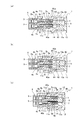
- FIG. 2 (a) to 2 (c) are cross-sectional views showing the overall configuration of the connector according to one embodiment of the present invention, in which FIG. 2 (a) shows a half-inserted state, and FIG. 2 (b).
- FIG. 2 is a view showing a state where a female terminal is inserted in a first fitting state
- FIG. 2C is a view showing a state where a female terminal is inserted in a second fitting state.
- FIG. 3 is an end view of the connector on the female terminal housing side.
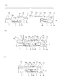
- 4 (a) to 4 (c) are cross-sectional views taken along arrow A3 in FIG. 3 from the direction of the arrow, and FIG. 4 (a) is a cross-sectional view showing a state before the first fitting state.
- 4 (b) is a cross-sectional view showing a state when starting the transition from the first fitting state to the second fitting state, and
- FIG. 4 (c) is a cross-sectional view showing the second fitting state. It is.
- FIGS. 1A to 2C show the configuration of a connector according to an embodiment of the present invention.
- FIG. 1A is a perspective view showing a state where the male terminal housing and the female terminal housing are separated (pre-fitting state), and
- FIG. 1B is a first fitting state (temporary fitting state) described later.
- FIG. 1C is a perspective view showing a second fitting state (main fitting state) described later.
- 1A to 1C the female terminals are not shown.
- 2A is a sectional view showing a half-insertion state, which will be described later
- FIG. 2B is a sectional view showing a state in which a female terminal is inserted in the first fitting state
- FIG. FIG. 5 is a cross-sectional view showing a state in which a female terminal is inserted in a second fitting state.
- the connector 1 includes a female terminal housing 5 in which a plurality of terminal accommodating chambers 4 into which female terminals 3 are inserted and accommodated, and the female terminals 3 are formed. And a male terminal housing 8 that holds a plurality of male terminals 7 connected to each other.
- the female terminal 3 has a locking hole 3d formed on one side surface of a cylindrical portion including a contact member 3a that can be elastically deformed in a lance 11 formed by an elastic member on the inner wall of the terminal accommodating chamber 4. Engaged. Then, by fitting the male terminal housing 8 and the female terminal housing 5, the connector 1 is connected by the sliding contact between the male terminal 7 and the contact member 3 a of the female terminal 3.
- the material of the female terminal housing 5 and the male terminal housing 8 is not particularly limited as long as it has elasticity. However, in the present embodiment, the case where both the housings 5 and 8 are made of resin is assumed as an example. .
- the female terminal 3 includes an elastically deformable contact member 3a, a cylindrical contact portion 3b, a crimp terminal portion 3c to which the electric wire 2 is crimped, and a ring attached to the outer periphery of the end portion of the electric wire 2. It is formed with a packing 2a.
- the terminal accommodating chamber 4 of the female terminal housing 5 includes a rectangular cylindrical accommodating chamber (hereinafter referred to as a rectangular cylindrical portion) 4 a in which the contact portion 3 b of the female terminal 3 is accommodated, a crimp terminal portion 3 c and a ring packing of the electric wire 2. And a cylindrical storage chamber (hereinafter referred to as a cylindrical portion) 4b in which 2a is stored.
- the rectangular tube portion 4a is positioned closer to the male terminal housing 8 than the cylindrical portion 4b.
- the lance 11 is formed on the inner wall of a predetermined side (the lower side in FIGS. 2A to 2C) of the rectangular cylindrical portion 4a of the terminal accommodating chamber 4.
- the lance 11 is made of the same resin as the female terminal housing 5 and cantilevered from the cylindrical portion 4b of the terminal accommodating chamber 4 in which the electric wire 2 is accommodated to the rectangular cylindrical portion 4a in which the female terminal 3 is accommodated.
- the lances 11 may be formed in the same number as the female terminals 3 with respect to the female terminal housing 5, one by one in the terminal accommodating chamber 4 according to the number of female terminals 3.
- the lance 11 is in a state before being engaged with the locking hole 3d of the female terminal 3 inserted into the terminal accommodating chamber 4 (the state shown in FIG. 2A.
- This state is hereinafter referred to as a half-inserted state).
- the lance 11 After being engaged with the locking hole 3d of the female terminal 3 which is pressed and elastically deformed by being pressed by the female terminal 3 and inserted into the terminal accommodating chamber 4 (the state shown in FIG. 2B). It is referred to as a state), and elastic deformation is restored.
- the lance 11 is elastically deformed so as to be retracted from the rectangular portion 4a of the terminal accommodating chamber 4 (downward in FIG. 2A).
- the lance 11 returns to the elastic deflection so as to advance to the rectangular portion 4a of the terminal accommodating chamber 4 at the position of the locking hole 3d of the female terminal 3 (upward in FIG. 2B). Deforms and engages with the locking hole 3 d of the female terminal 3.
- the female terminal housing 5 is provided with a cylindrical female hood 12 so as to protrude from the outer peripheral surface of the rectangular portion 4 a of the terminal accommodating chamber 4.
- each male terminal 7 is made of a plate-like conductor, and its tip enters the rectangular portion 4a of the terminal accommodating chamber 4 of the female terminal housing 5, and is formed so as to be slidably connected to the contact member 3a of the female terminal 3. Yes.
- the plurality of male terminals 7 are connected to the bus bar 6 and connected and fixed to an external conductor (for example, a ground conductor) via the bus bar 6.
- the base portion 8 a of the male terminal housing 8 is formed with a body portion 9 on which the female hood 12 of the female terminal housing 5 is crowned.
- the connector 1 can have a waterproof structure.
- the connector 1 is configured such that the male terminal housing 8 and the female terminal housing 5 are fitted and the male terminal 7 is slidably connected to the contact member 3a of the female terminal 3.
- the male terminal housing 8 and the female terminal housing 5 have a first engaging portion and a second engaging portion that engage with each other at the first fitting position and the second fitting position at the time of fitting, Mates in two stages.
- the first fitting position is a position where the locking hole 3 d of the female terminal 3 is engaged with the lance 11 and the male terminal 7 is the female terminal 3. It is set in front of the position in contact with the contact member 3a.
- the second fitting position is set to a position where the male terminal 7 is in sliding contact with the contact member 3a of the female terminal 3 as shown in FIGS. 1 (c) and 2 (c).
- the state in which the male terminal housing 8 and the female terminal housing 5 are in the first fitting position is referred to as a first fitting state
- the state in the second fitting position is referred to as a second fitting state.
- the locking hole 3d of the female terminal 3 and the lance 11 are engaged, and both correspond to the main insertion state.
- the connector 1 shifts the male terminal housing 8 and the female terminal housing 5 from the first fitting state to the second fitting state (moves from the first fitting position to the second fitting position).
- the male terminal 7 is in sliding contact with the contact member 3 a of the female terminal 3.
- the male terminal housing 8 includes an interference portion (hereinafter referred to as “interference portion”) that interferes with the lance 11 according to the engagement state (half-insertion state and full-insertion state) between the locking hole 3d of the female terminal 3 and the lance 11.
- a semi-insertion detection pin) 40 projects toward the female terminal housing 5.
- FIGS. 2 (a) to 2 (c) show, as an example, the configuration of a plate-like interference portion 40 extended toward the lance 11.
- the half-insertion detection pin 40 is the number of the lances 11, in other words, the number of the female terminals 3 inserted into the terminal accommodating chamber 4 (in other words, the male terminals provided in the male terminal housing 8.
- the same number as that of the male terminal housing 8 may be provided according to the number of 7).
- eight half-insertion detections are performed so as to correspond to the eight female terminals 3 inserted into the terminal accommodating chamber 4.
- a pin 40 is provided on the male terminal housing 8.
- the half-insertion detecting pin 40 interferes with the lance 11 before the engagement between the locking hole 3d of the female terminal 3 inserted into the terminal accommodating chamber 4 and the lance 11, that is, in the half-inserted state.
- the sliding contact of the male terminal 7 to 3a is regulated.
- the half-insertion detection pin 40 does not interfere with the lance 11 after the engagement between the locking hole 3d of the female terminal 3 inserted into the terminal accommodating chamber 4 and the lance 11, that is, in the fully inserted state.
- the sliding contact of the male terminal 7 to the contact member 3a of the female terminal 3 is allowed. That is, the half-insertion detection pin 40 interferes with the lance 11 that has been elastically deformed and deformed in the half-inserted state, but does not interfere with the lance 11 that has been elastically deformed and deformed in the fully-inserted state.
- the engagement state between the lance 11 and the locking hole 3d of the female terminal 3 is established. Is in a half-inserted state, the lance 11 is elastically bent and deformed so as to be pushed out by the female terminal 3 and retreat from the rectangular portion 4 a of the terminal accommodating chamber 4. In this state of elastic deformation, the lance 11 closes the cantilever gap 11a.
- the gap portion 11a is a gap serving as an entry path for the semi-insertion detection pin 40 when the male terminal 7 is moved to a position (second fitting position) where the male terminal 7 is in sliding contact with the contact member 3a of the female terminal 3.
- the elastically deformed lance 11 is in a state of closing the approach path of the half-insertion detection pin 40. Therefore, even if the male terminal housing 8 and the female terminal housing 5 are shifted from the first fitting state to the second fitting state so that the female terminal 3 is brought into sliding contact with the contact member 3a, the half-insertion detection pin 40 is used. Since it interferes with the lance 11, the half-insertion detection pin 40 cannot be allowed to enter the gap portion 11a. That is, in the half-inserted state, the male terminal housing 8 and the female terminal housing 5 cannot be shifted from the first fitting state to the second fitting state, and the male terminal 7 is moved to the contact member 3a of the female terminal 3. It is impossible to make sliding contact.
- the half-insertion detection pin 40 and the lance 11 do not interfere with each other and the tip portions face each other in a non-contact state (FIG. 2 ( b)).
- the half-insertion detection pin 40 is configured to protrude from the male terminal 7 toward the female terminal housing 5 (in short, the lance 11), and the male terminal 7 is in the first fitted state, It does not slidably contact the contact member 3a of the female terminal 3.
- the pin 40 enters the gap portion 11a of the lance 11 (the state shown in FIG. 2C).
- the half-insertion detection pin 40 has a distal end so that it can smoothly enter the gap portion 11a when it hits the lance 11 during the transition from the first fitting state to the second fitting state.
- the abutting surface in FIG. 2 (a) to FIG. 2 (c), the tip upper surface
- the tip of the male terminal 7 enters the rectangular portion 4a of the terminal accommodating chamber 4 and enters the second fitting position.
- the male terminal 7 can come into sliding contact with the contact member 3 a of the female terminal 3. That is, in this insertion state, the male terminal housing 8 and the female terminal housing 5 can be shifted from the first fitting state to the second fitting state, and the male terminal 7 slides on the contact member 3 a of the female terminal 3. It becomes possible to touch.
- the half-insertion detection pin 40 detects whether the engagement state between the locking hole 3d of the female terminal 3 and the lance 11 is the half-insertion state or the full-insertion state (in short, the operator).
- the male terminal housing 8 and the female terminal housing 5 are shifted from the first fitting state to the second fitting state, and the male terminal 7 is in sliding contact with the contact member 3a of the female terminal 3. It has a function to detect whether or not.
- the first engaging portion includes a temporary locking arm 13 provided on the male terminal housing 8 and a temporary locking projection 14 provided on the female terminal housing 5.
- the temporary locking arm 13 is directed from the outer peripheral surface of the base portion 8a of the male terminal housing 8 (upper and lower surfaces in FIGS. 1 (a) to 2 (c)) to the outer peripheral surface of the female hood 12 of the female terminal housing 5. It is extended in the shape of a plate and has a temporary locking groove 13 a formed by extending in the fitting direction between the male terminal housing 8 and the female terminal housing 5.
- the temporary locking protrusion 14 protrudes from the outer peripheral surface of the female hood 12 of the female terminal housing 5 (upper and lower surfaces in FIGS. 1 (a) to 2 (c)) corresponding to the temporary locking groove 13a. It is provided as follows. Then, when the fitting between the male terminal housing 8 and the female terminal housing 5 is started, the abutting surface at the tip of the temporary locking arm 13 is made so that the temporary locking arm 13 hits the temporary locking protrusion 14 and easily rides up. (In FIGS. 2 (a) to 2 (c), the tip lower surface or the tip upper surface) and the abutting portion (the upper end or the lower end in the drawings) are inclined so as to be along each other. Is formed.
- the temporary locking projection 14 falls into the temporary locking groove 13a of the temporary locking arm 13 and becomes the first fitting position. Then, the female terminal 3 is inserted into the terminal accommodating chamber 4, and the engagement hole 3d of the female terminal 3 is locked to the lance 11 to prevent the female terminal 3 from coming off (the state shown in FIG. 2B). Thereby, the male terminal housing 8 and the female terminal housing 5 will be in a 1st fitting state. In this way, in the first fitting state, in order to release the fitting between the male terminal housing 8 and the female terminal housing 5, the temporary locking arm 13 is warped and the temporary locking groove 13a and the temporary locking projection 14 are released. However, it is sufficient to use a releasing force that only warps the plate-like temporary locking arm 13.
- the second engaging portion includes a pair of main locking arms 15 provided on the male terminal housing 8 and a pair of main locking projections 16 provided on the female terminal housing 5.
- the locking arm 15 extends from the outer peripheral surface of the base portion 8a of the male terminal housing 8 (the side surface along the arrows 30 and 31 in FIGS. 1A to 1C) to the female hood 12 of the female terminal housing 5. It has a main locking groove 15 a that is extended in the fitting direction between the male terminal housing 8 and the female terminal housing 5.
- the main locking projection 16 corresponds to the main locking groove 15a, and the outer peripheral surface of the female hood 12 of the female terminal housing 5 (in FIGS. 1 (a) to 1 (c), arrows 30 and 31). (Side side surface).
- the main locking arm 15 abuts against the main locking projection 16 so that it can easily get on.
- the abutting portion at the tip of the main locking arm 15 and the abutting portion of the temporary locking protrusion 14 are formed so as to be inclined with each other.
- the second engagement portion releases the contact portion and the contacted portion that contact each other at the first fitting position, and the contact between the contact portion and the contacted portion.
- a contact release portion is configured to elastically deform the contact portion with respect to the contacted portion when the male terminal housing 8 and the female terminal housing 5 are moved from the first fitting position to the second fitting position.
- 3 and 4 show the configuration of the contact portion, the contacted portion, and the contact release portion.
- FIG. 3 is an end view of the connector 1 on the female terminal housing 5 side.
- FIG. 4 is a cross-sectional view of the abutting portion, the abutted portion, and the abutting release portion in the arrow A3 portion of FIG.
- FIG. 4B is a cross-sectional view showing the state before the state
- FIG. 4B is a cross-sectional view showing a state when the transition from the first fitting state to the second fitting state is started
- FIG. It is sectional drawing which shows these fitting states.
- the main locking arm 15 is provided with an arm locking portion 15b passed to the main locking groove 15a as a contact portion so as to intersect the main locking groove 15a.
- the arm locking portion 15b is formed in the first engagement position from the first engagement position to the second engagement position in the moving direction (the right side in FIG. 4B). 16 abuts.
- the main locking projection 16 is provided on the female hood 12 of the female terminal housing 5 at a position where it just abuts against the arm locking portion 15 b in the first fitting position.
- the main locking protrusion 16 functions not only as the second engaging portion but also as a contacted portion.
- the locking arm 15 is provided with a release protrusion 15c at the tip of the arm as a contact release portion.
- the release protrusion 15 c extends from the tip of the main body portion 15 d of the main locking arm 15 toward the outer peripheral surface of the female hood 12 of the female terminal housing 5.
- the release protrusion 15c is configured such that its width dimension (for example, the dimension along the vertical direction in FIGS. 1A to 1C) is smaller (narrower) than the width dimension of the main body portion 15d.
- the release protrusion 15c bulges outward (upward in FIGS. 4 (a) to 4 (c)) so as to be thicker than the thickness (plate thickness) of the main body 15d.
- the inner side of the release protrusion 15c (the lower side in FIGS. 4A to 4C) is flush with the body portion 15d and is flat along the outer peripheral surface of the female terminal housing 5. ing.
- the female terminal housing 5 is formed with a release recess 12a as a contact release portion.
- the release recess 12a is formed so as to recess the outer peripheral surface of the female hood 12 (the side surface along the arrows 30 and 31 in FIGS. 1 (a) to 1 (c)) corresponding to the release protrusion 15c. Yes.
- the release recess 12a functions as a recess (an escape portion) that can push the release projection 15c toward the release recess 12a and accommodate the pushed release projection 15c. Therefore, the size of the release recess 12a (the length corresponding to the horizontal dimension in FIGS.
- S) may be set so that the release protrusion 15c can be pushed in and accommodated.
- the entire release protrusion 15c need not be accommodated in the release recess 12a.
- the arm locking portion 15b can be elastically deformed and deformed with respect to the main locking protrusion 16 to release the mutual contact.
- the depth of the release recess 12a (corresponding to the vertical dimension in FIGS.
- the female terminal housing 5 has a pair of protrusion support portions 12b that support the release protrusions 15c so as to sandwich the release protrusions 15c in the second fitted state (see FIG. 4 (a) to FIG. 4A). It protrudes from the left end portion in FIG.
- the arm locking portion 15b is made the main locking protrusion 16 when the transition from the first fitting state to the second fitting state is started. On the other hand, they can be elastically deformed and released from each other.
- the main locking arm 15 is configured such that the arm locking portion 15b is in a state where the release protrusion 15c faces the release recess 12a. It is in a state of being in contact with the main locking projection 16 (a state indicated by a solid line in FIG. 4B).
- the release protrusion 15c is supported so as to be sandwiched between the pair of protrusion support portions 12b. Thereby, the male terminal housing 8 and the female terminal housing 5 can be made into the 2nd fitting state (state shown to FIG.1 (c) and FIG.4 (c)).
- the pushing force F to the releasing recess 12a is applied to the releasing projection 15c, and the elastic locking deformation of the main locking arm 15 is performed.
- the load (initial load) applied during the transition can be small.
- the transition from the first fitting state to the second fitting state cannot be performed, and in this case, an interference load between the half-insertion detection pin 40 and the lance 11 is loaded. Resistance is generated by being performed. Since such resistance is much larger than the initial load, the operator can easily and clearly distinguish between the two.
- the male terminal housing 8 and the female terminal housing 5 are separated into two stages (first fitting state and second fitting state).
- the first fitting position is a position where the locking hole 3d of the female terminal 3 is engaged with the lance 11, and is closer to the front than the position where the male terminal 7 is in sliding contact with the contact member 3a of the female terminal 3. Is set. Since the first fitting state is a temporary fitting state, in order to obtain the first fitting state, it is sufficient that the female terminal 3 applies a load corresponding to an insertion force for elastically deforming the lance 11. .
- the main locking arm 15 contacts the main locking projection 16, and the temporary locking groove 13 a of the temporary locking arm 13 and the temporary locking projection 14 are locked. From this, even if a force is applied in any direction of the arrows 30 and 31 shown in FIG.
- a pushing force F to the release recess 12a is applied to the release protrusion 15c to cause the main locking arm 15 to be elastically bent and deformed.
- the release projection 15c moves over the locking projection 16. If the male terminal housing 8 and the female terminal housing 5 are moved to the second fitting position as they are and the pushing force F against the release protrusion 15c is released to fit these housings 8 and 5, the contact member 3a of the female terminal 3 is fitted.
- the male terminal 7 is slid and inserted to a predetermined position while the two terminals are connected, and the second fitting state is obtained.
- the second fitting state is a state of the main fitting, and the load applied to make the state of the main fitting is the bending force of the contact member 3a of the female terminal 3, the male terminal 7 and the contact member 3a. No load is applied to the lance 11 for elastic deformation.
- the load applied to connect the male terminal 7 and the female terminal 3 can be dispersed into the load for making the first fitting state and the load for making the second fitting state, and such connection
- the maximum load at can be reduced.
- the half insertion state with respect to the terminal storage chamber 4 of this female terminal 3 is easy and It is possible to grasp with certainty. That is, initial load (drag) when shifting from the first fitting state (temporary fitting state) to the second fitting state (main fitting state) and resistance (feeling) when the female terminal is half inserted
- initial load drag
- temporary fitting state temporary fitting state
- main fitting state main fitting state
- resistance feeling
- the male terminal housing 8 and the female terminal housing 5 are erroneously shifted from the temporarily fitted state to the fully fitted state even though the female terminal 3 is in the half-inserted state. Therefore, it is possible to reliably prevent work mistakes. As a result, it is possible to avoid a problem in which an excessive pressing force is applied to the male terminal 7 and the female terminal 3 to cause damage.
- the present invention is not limited to the above-described embodiment, and can be appropriately modified and improved.
- the material, shape, dimension, numerical value, form, number, arrangement location, and the like of each component in the above-described embodiment are arbitrary and are not limited as long as the present invention can be achieved.
- (7) is provided with a male terminal housing (8), and the female terminal (3) is a latch formed on one side surface of a cylindrical portion including an elastically deformable contact member (3a).
- the hole (3d) is engaged with a lance (11) formed of an elastic member on the inner wall of the terminal accommodating chamber (4), and the male terminal housing (8) and the female terminal housing (5) are engaged with each other.
- the male terminal (7) is a connector (1) connected in sliding contact with the contact member (3a) of the female terminal (3)
- the male terminal housing (8) includes an interference portion (40) that interferes with the lance (11) according to the engagement state between the locking hole (3d) of the female terminal (3) and the lance (11). Projecting toward the female terminal housing (5), The interference portion (40) is connected to the lance (11) before the engagement between the locking hole (3d) of the female terminal (3) inserted into the terminal accommodating chamber (4) and the lance (11).
- the said interference part (40) is a connector (1) of said [1] which interferes with the said lance (11) elastically deformed, and does not interfere with the said lance (11) after elastic deformation.
- the male terminal (7) is insert-molded in the male terminal housing (8),
- the male terminal housing (8) and the female terminal housing (5) have a first engagement portion and a second engagement portion that are engaged with each other at the first fitting position and the second fitting position at the time of fitting. Fitted with The first fitting position is a position where the locking hole (3d) of the female terminal (3) is engaged with the lance (11), and the male terminal (7) is the female terminal (3).
- the second fitting position is set to a position where the male terminal (7) is in sliding contact with the contact member (3d) of the female terminal (3)
- the second engaging portion of the male terminal housing (8) and the female terminal housing (5) includes an abutting portion (15b) and an abutted portion (16) that abut each other at the first fitting position.
- a contact release portion (15c) for releasing contact of the contact portion (15b) and the contacted portion (16) The contact release portion (15c) is configured to move the contact when the male terminal housing (8) and the female terminal housing (5) are moved from the first fitting position to the second fitting position.
- the connector according to [1] or [2], wherein the portion (15b) is elastically bent and deformed with respect to the contacted portion (16) to release mutual contact.
Landscapes
- Connector Housings Or Holding Contact Members (AREA)
- Details Of Connecting Devices For Male And Female Coupling (AREA)
Description
本発明は、複数の雌端子と複数の雄端子とを電気的に接続するコネクタの嵌合構造に関する。
複数の雌端子がそれぞれ収容される複数の雌端子収容室が形成された雌端子用のハウジングと、複数の雌端子に接続される複数の雄端子を保持してなる雄端子用のハウジングを一体的に形成したコネクタが知られている(例えば、特許文献1参照)。これによれば、複数の雄端子を雄端子用のハウジングに圧入して雄端子用のハウジングにおける雌端子収容室内に突出させ、複数の雌端子をそれぞれの雌端子収容室に挿入して雌端子と雄端子を電気的に接続する。特に、特許文献1に記載のコネクタによれば、雌端子を弾性変形可能な接点部材を内包して筒状に形成し、その筒の一側面に形成された係止穴を雌端子収容室の内壁に弾性部材により形成されたランスに係合させて、雌端子を抜け止めしている。また、コネクタは、両ハウジングの嵌合状態で、雄端子を雌端子の接点部材に摺接させて電気的に接続するように構成されている。
その一方で、特許文献1に記載のコネクタは、雌端子の挿入力を軽減することについて配慮されていない。すなわち、配線に接続された雌端子を端子収容室の所定位置に挿入するためには、ランスを撓ませる弾性変形力に加えて、雌端子の接点部材を撓ませつつ雄端子を摺動させて所定の位置まで挿入する挿入力が必要になる。この挿入力が大きいために、雌端子挿入作業を行う作業者は半挿入状態にもかかわらず端子挿入作業を終わらせてしまい、雌端子の挿入不具合が発生するおそれがある。
そこで、雄端子ハウジングと雌端子ハウジングを分離して形成し、雌端子を端子収容室に挿入し、ランスに係合する接続段階(第1の接続)と、ランスに係合した雌端子の接点部材に雄端子を摺接させる接続段階(第2の接続)に分けて、雌端子と雄端子との接続を行うことが考えられる。この場合、第1の接続を行うための第1の嵌合位置(仮嵌合状態)と、第2の接続を行うための第2の嵌合位置(本嵌合状態)で雄端子ハウジングと雌端子ハウジングをそれぞれ嵌合可能な構成とすればよい。
しかしながら、このような構成とした場合であっても、雄端子ハウジングと雌端子ハウジングを仮嵌合状態から本嵌合状態へ移行する際、雌端子が半挿入状態となっていないことが容易かつ確実に把握可能であることが必要となる。例えば、仮嵌合状態から本嵌合状態へ移行させる際の初期荷重(抗力)と雌端子の半挿入状態時の抵抗(フィーリング)との区別が付き難い場合、雌端子が半挿入状態となっているにもかかわらず、雄端子ハウジングと雌端子ハウジングを誤って仮嵌合状態から本嵌合状態へ移行してしまうおそれがある。その際、雄端子や雌端子に過剰な押圧力が負荷されて損傷が生じる可能性もある。
本発明はこれを踏まえてなされたものであり、その解決しようとする課題は、雄端子と雌端子の接続時の最大荷重(負荷)を低減しつつ、かかる雌端子の端子収容室に対する半挿入状態を容易かつ確実に把握可能とすることにある。
上記課題を解決するため、本発明は、次の構成のコネクタに存する。雌端子がそれぞれ挿入されて収容される複数の端子収容室が形成された雌端子ハウジングと、前記雌端子に接続される複数の雄端子を保持してなる雄端子ハウジングとを備え、前記雌端子は弾性変形可能な接点部材を内包してなる筒部の一側面に形成された係止穴が前記端子収容室の内壁に弾性部材により形成されたランスに係合され、前記雄端子ハウジングと前記雌端子ハウジングとの嵌合にともない前記雄端子が前記雌端子の前記接点部材に摺接して接続されるコネクタであって、前記雄端子ハウジングには、前記雌端子の係止穴と前記ランスとの係合状態に応じて前記ランスと干渉する干渉部が前記雌端子ハウジングに向けて突設され、前記干渉部は、前記端子収容室に挿入された前記雌端子の係止穴と前記ランスとの係合前、前記ランスと干渉して前記雌端子の接点部材への前記雄端子の摺接を規制し、前記端子収容室に挿入された前記雌端子の係止穴と前記ランスとの係合後、前記ランスとは干渉せずに前記雌端子の接点部材への前記雄端子の摺接を許容するコネクタ。
この構成のコネクタによれば、端子収容室に挿入された雌端子の係止穴とランスとが係合した状態(本挿入状態)においては、雄端子を雌端子の接点部材に摺接させて接続することができる。一方、端子収容室に挿入された雌端子の係止穴とランスとが係合していない状態(半挿入状態)においては、干渉部をランスと干渉させることができ、雄端子を雌端子の接点部材に接続させないようにすることができる。このように、半挿入状態と本挿入状態を容易に区別することができ、雄端子を無理やり雌端子の接点部材に摺接させて接続するような事態を防止することが可能となる。
この場合、前記ランスは、前記端子収容室に挿入された前記雌端子の係止穴との係合前、該雌端子に押圧されて弾性撓み変形され、前記端子収容室に挿入された前記雌端子の係止穴との係合後、弾性撓み復帰変形され、前記干渉部は、弾性撓み変形された前記ランスと干渉し、弾性撓み復帰変形された前記ランスとは干渉しない構成とすればよい。
また、前記雄端子は、前記雄端子ハウジングにインサート成形され、前記雄端子ハウジングと前記雌端子ハウジングは、嵌合時に第1の嵌合位置と第2の嵌合位置で互いに係合する第1係合部と第2係合部を有して嵌合され、前記第1の嵌合位置は、前記雌端子の係止穴が前記ランスに係合した位置であって、前記雄端子が前記雌端子の接点部材に摺接する位置よりも手前に設定され、前記第2の嵌合位置は、前記雄端子が前記雌端子の接点部材に摺接する位置に設定され、前記雄端子ハウジングと前記雌端子ハウジングの前記第2係合部は、前記第1の嵌合位置において互いに当接する当接部及び被当接部と、前記当接部及び前記被当接部の当接を解除する当接解除部とを有し、前記当接解除部は、前記雄端子ハウジング及び前記雌端子ハウジングを前記第1の嵌合位置から前記第2の嵌合位置へ移動する際に、前記当接部を前記被当接部に対して弾性撓み変形させて互いの当接を解除する構成とすることが可能である。
本発明によれば、雄端子と雌端子の接続時の最大荷重(負荷)を低減することができるとともに、かかる雌端子の端子収容室に対する半挿入状態を容易かつ確実に把握することができる。
以上、本発明について簡潔に説明した。更に、以下に説明される発明を実施するための形態(以下、「実施形態」という。)を添付の図面を参照して通読することにより、本発明の詳細は更に明確化されるであろう。
以下、本発明のコネクタについて、添付図面を参照して説明する。図1(a)~図2(c)には、本発明の一実施形態に係るコネクタの構成を示している。図1(a)は、雄端子ハウジングと雌端子ハウジングを分離させた状態(嵌合前状態)を示す斜視図、図1(b)は、後述する第1の嵌合状態(仮嵌合状態)を示す斜視図、図1(c)は、後述する第2の嵌合状態(本嵌合状態)を示す斜視図である。なお、図1(a)~図1(c)において、雌端子は図示を省略している。また、図2(a)は、後述する半挿入状態を示す断面図、図2(b)は、第1の嵌合状態において雌端子を挿入した状態を示す断面図、図2(c)は、第2の嵌合状態において雌端子が挿入された状態を示す断面図である。
図1(a)~図2(c)に示すように、コネクタ1は、雌端子3がそれぞれ挿入されて収容される複数の端子収容室4が形成された雌端子ハウジング5と、雌端子3に接続される複数の雄端子7を保持してなる雄端子ハウジング8とを備えている。この場合、雌端子3は、弾性変形可能な接点部材3aを内包してなる筒部の一側面に形成された係止穴3dが端子収容室4の内壁に弾性部材により形成されたランス11に係合される。そして、雄端子ハウジング8と雌端子ハウジング5とを嵌合することで、コネクタ1は、雄端子7と雌端子3の接点部材3aとが摺接して接続される。なお、雌端子ハウジング5と雄端子ハウジング8の材質は弾性を有していれば特に限定されないが、本実施形態においてはいずれのハウジング5,8も樹脂により構成されている場合を一例として想定する。
雌端子3は、弾性変形可能な接点部材3aを内包して筒状に形成された接点部3bと、電線2が圧着された圧着端子部3cと、電線2の端部外周に装着されたリングパッキン2aを備えて形成されている。雌端子ハウジング5の端子収容室4は、雌端子3の接点部3bが収容される矩形筒状の収容室(以下、矩形筒部という。)4aと、圧着端子部3c及び電線2のリングパッキン2aが収容される円筒状の収容室(同、円筒部という。)4bとを備えて形成されている。矩形筒部4aは、円筒部4bよりも雄端子ハウジング8側に位置付けられている。
ランス11は、端子収容室4の矩形筒部4aの所定側(図2(a)~図2(c)においては、下側)の内壁に形成されている。この場合、ランス11は、雌端子ハウジング5と同一の樹脂で、電線2が収容される端子収容室4の円筒部4bから、雌端子3が収容される矩形筒部4aに伸延させて片持ち状に一体成形されている。なお、ランス11は、雌端子3の数に応じて、端子収容室4に1つずつ、雌端子ハウジング5に対して雌端子3と同数形成すればよい。
また、ランス11は、端子収容室4に挿入された雌端子3の係止穴3dとの係合前(図2(a)に示す状態。以下、この状態を半挿入状態という。)、該雌端子3に押圧されて弾性撓み変形され、端子収容室4に挿入された雌端子3の係止穴3dとの係合後(図2(b)に示す状態。以下、この状態を本挿入状態という。)、弾性撓み復帰変形される。具体的には、半挿入状態において、ランス11は端子収容室4の矩形状部4aから退出するように(図2(a)においては、下側に)弾性撓み変形する。そして、本挿入状態において、ランス11は雌端子3の係止穴3dの位置で端子収容室4の矩形状部4aへ進出するように(図2(b)においては、上側に)弾性撓み復帰変形し、雌端子3の係止穴3dと係合する。このように、本挿入状態においては、雌端子3がランス11と係止され、雌端子3の抜け止めがなされる。なお、雌端子ハウジング5には、端子収容室4の矩形状部4aの外周面から張り出すように筒状の雌フード12が設けられている。
雄端子ハウジング8には、雌端子3に挿入接続される複数の雄端子7がインサート成形されて保持されている。各雄端子7は、板状の導体からなり、その先端が雌端子ハウジング5の端子収容室4の矩形状部4aに進入し、雌端子3の接点部材3aと摺動接続可能に形成されている。また、複数の雄端子7は、バスバ6に接続され、バスバ6を介して外部導体(一例として、接地導体)に接続固定されるようになっている。雄端子ハウジング8の基部8aには、雌端子ハウジング5の雌フード12が被冠される本体部9が形成されている。なお、本体部9と雌フード12との間にリング状の密封部材(例えば、防水パッキン等)を装着することで、雄端子7と雌端子3との接続部分への浸水を防止することができ、コネクタ1を防水構造とすることが可能となる。
上述したように、コネクタ1は、雄端子ハウジング8と雌端子ハウジング5を嵌合させて雄端子7を雌端子3の接点部材3aに摺接させて接続するように構成されている。この場合、雄端子ハウジング8と雌端子ハウジング5は、嵌合時に第1の嵌合位置と第2の嵌合位置で互いに係合する第1係合部と第2係合部を有し、2段階で嵌合する。第1の嵌合位置は、図1(b)及び図2(b)に示すように、雌端子3の係止穴3dがランス11に係合した位置で、かつ雄端子7が雌端子3の接点部材3aに摺接する位置よりも手前に設定されている。また、第2の嵌合位置は、図1(c)及び図2(c)に示すように、雄端子7が雌端子3の接点部材3aに摺接する位置に設定されている。以下の説明においては、雄端子ハウジング8と雌端子ハウジング5が第1の嵌合位置にある状態を第1の嵌合状態、第2の嵌合位置にある状態を第2の嵌合状態という。なお、第1の嵌合状態及び第2の嵌合状態においては、雌端子3の係止穴3dとランス11とが係合された状態となっており、いずれも本挿入状態に相当する。このように、コネクタ1は、雄端子ハウジング8及び雌端子ハウジング5を第1の嵌合状態から第2の嵌合状態へ移行させる(第1の嵌合位置から第2の嵌合位置へ移動させる)ことで、雄端子7が雌端子3の接点部材3aと摺接する構成となっている。
本実施形態において、雄端子ハウジング8には、雌端子3の係止穴3dとランス11との係合状態(半挿入状態及び本挿入状態)に応じてランス11と干渉する干渉部(以下、半挿入検知ピンという。)40が雌端子ハウジング5に向けて突設されている。図1(a)及び図2(a)~図2(c)には、ランス11に向けて伸延された板状の干渉部40の構成を一例として示している。なお、半挿入検知ピン40は、ランス11の数、別の捉え方をすれば、端子収容室4に挿入される雌端子3の数(換言すれば、雄端子ハウジング8に装備された雄端子7の数)に応じて、これと同数だけ雄端子ハウジング8に対して設ければよい。一例として、図1(a)及び図2(a)~図2(c)に示す構成においては、端子収容室4に挿入される8つの雌端子3に対応するように、8つの半挿入検知ピン40が雄端子ハウジング8に設けられている。
半挿入検知ピン40は、端子収容室4に挿入された雌端子3の係止穴3dとランス11との係合前、つまり半挿入状態において、ランス11と干渉して雌端子3の接点部材3aへの雄端子7の摺接を規制する。その一方で、半挿入検知ピン40は、端子収容室4に挿入された雌端子3の係止穴3dとランス11との係合後、つまり本挿入状態において、ランス11とは干渉せずに雌端子3の接点部材3aへの雄端子7の摺接を許容する。すなわち、半挿入検知ピン40は、半挿入状態において弾性撓み変形されたランス11と干渉するのに対し、本挿入状態において弾性撓み復帰変形されたランス11とは干渉しない。
ここで、図2(a)に示すように、雄端子ハウジング8及び雌端子ハウジング5が第1の嵌合状態となる前に、ランス11と雌端子3の係止穴3dとの係合状態が半挿入状態となっている場合、かかるランス11は、雌端子3に押圧されて端子収容室4の矩形状部4aから退出するように弾性撓み変形されている。このように弾性撓み変形した状態においては、ランス11が片持ち部分の空隙部11aを塞いだ状態となる。空隙部11aは、雄端子7を雌端子3の接点部材3aに摺接する位置(第2の嵌合位置)へ移動させる際に、半挿入検知ピン40の進入経路となる空隙である。つまり、弾性撓み変形したランス11は、かかる半挿入検知ピン40の進入経路を塞いだ状態となっている。したがって、雌端子3を接点部材3aに摺接させるべく、雄端子ハウジング8及び雌端子ハウジング5を第1の嵌合状態から第2の嵌合状態へ移行させようとしても、半挿入検知ピン40がランス11と干渉するため、半挿入検知ピン40を空隙部11aへ進入させることはできない。すなわち、半挿入状態では、雄端子ハウジング8及び雌端子ハウジング5を第1の嵌合状態から第2の嵌合状態へ移行させることができず、雄端子7を雌端子3の接点部材3aに摺接させることが不可能となる。
これに対し、第1の嵌合状態(本挿入状態に相当)においては、半挿入検知ピン40とランス11は干渉せず、先端部同士を互いに非接触状態で対向している(図2(b)に示す状態)。また、半挿入検知ピン40は、雄端子7よりも雌端子ハウジング5(端的には、ランス11)へ向けて突出した構成となっており、雄端子7は、第1の嵌合状態では、雌端子3の接点部材3aに摺接しない。そして、雄端子7を雌端子3の接点部材3aに摺接させるべく、雄端子ハウジング8及び雌端子ハウジング5を第1の嵌合状態から第2の嵌合状態へ移行する際、半挿入検知ピン40は、ランス11の空隙部11aへ進入する(図2(c)に示す状態)。なお、半挿入検知ピン40は、第1の嵌合状態から第2の嵌合状態への移行時にランス11に突き当たった際、空隙部11aへスムーズに進入することが可能となるように先端の突き当て面(図2(a)~図2(c)においては、先端上面)40aをランス11へ向けて下降するように傾斜した構成となっている。このように半挿入検知ピン40がランス11の背面側の空隙部11aへ進入することで、雄端子7の先端が端子収容室4の矩形状部4aに進入して第2の嵌合位置に位置付けられ、雄端子7が雌端子3の接点部材3aに摺接することができる。すなわち、本挿入状態では、雄端子ハウジング8及び雌端子ハウジング5を第1の嵌合状態から第2の嵌合状態へ移行することができ、雄端子7が雌端子3の接点部材3aに摺接することが可能となる。
このように、半挿入検知ピン40は、雌端子3の係止穴3dとランス11との係合状態が半挿入状態もしくは本挿入状態のいずれであるのかを検知する(端的には、作業者に認識させる)機能、ひいては、雄端子ハウジング8及び雌端子ハウジング5を第1の嵌合状態から第2の嵌合状態へ移行させ、雄端子7が雌端子3の接点部材3aに摺接することの可否を検知する機能を有している。
次に、第1の嵌合位置と第2の嵌合位置で係合する第1係合部と第2係合部の構成について説明する。第1の係合部は、雄端子ハウジング8に設けられた仮係止アーム13と、雌端子ハウジング5に設けられた仮係止突起14を備えて構成されている。仮係止アーム13は、雄端子ハウジング8の基部8aの外周面(図1(a)~図2(c)においては、上下面)から雌端子ハウジング5の雌フード12の外周面に向けて板状に伸延されており、雄端子ハウジング8と雌端子ハウジング5との嵌合方向に伸延して形成された仮係止溝13aを有している。また、仮係止突起14は、仮係止溝13aに対応して雌端子ハウジング5の雌フード12の外周面(図1(a)~図2(c)においては、上下面)から突出するように設けられている。そして、雄端子ハウジング8と雌端子ハウジング5の嵌合を開始した時、仮係止アーム13が仮係止突起14に突き当たって乗り上がり易いように、仮係止アーム13の先端の突き当て面(図2(a)~図2(c)においては、先端下面もしくは先端上面)及び仮係止突起14の突き当て部位(同各図においては、上端部もしくは下端部)が互いに沿うように傾斜して形成されている。さらに、雄端子ハウジング8と雌端子ハウジング5の嵌合を進めると、仮係止突起14が仮係止アーム13の仮係止溝13a内に落ち込んで第1の嵌合位置になる。そして、雌端子3を端子収容室4に挿入し、雌端子3の係合穴3dをランス11に係止させて抜け止めする(図2(b)に示す状態)。これにより、雄端子ハウジング8及び雌端子ハウジング5は、第1の嵌合状態となる。このように第1の嵌合状態となると、雄端子ハウジング8と雌端子ハウジング5との嵌合を解除するには、仮係止アーム13を反らせて仮係止溝13aと仮係止突起14との係止を解除することになるが、板状の仮係止アーム13を反らすだけの解除力で済む。
一方、第2の係合部は、雄端子ハウジング8に設けられた一対の本係止アーム15と、雌端子ハウジング5に設けられた一対の本係止突起16を備えて構成されている。本係止アーム15は、雄端子ハウジング8の基部8aの外周面(図1(a)~図1(c)においては、矢印30,31に沿った側面)から雌端子ハウジング5の雌フード12の外周面に向けて板状に伸延されており、雄端子ハウジング8と雌端子ハウジング5との嵌合方向に伸延して形成された本係止溝15aを有している。また、本係止突起16は、本係止溝15aに対応して雌端子ハウジング5の雌フード12の外周面(図1(a)~図1(c)おいては、矢印30,31に沿った側面)から突出するように設けられている。そして、雄端子ハウジング8及び雌端子ハウジング5を第1の嵌合位置から第2の嵌合位置へ移動させる時、本係止アーム15が本係止突起16に突き当たって乗り上がり易いように、本係止アーム15の先端の突き当て部位及び仮係止突起14の突き当て部位が互いに沿うように傾斜して形成されている。
また、本実施形態において、第2の係合部は、第1の嵌合位置において互いに当接する当接部及び被当接部と、これら当接部及び被当接部の当接を解除する当接解除部とを有している。かかる当接解除部は、雄端子ハウジング8及び雌端子ハウジング5を第1の嵌合位置から第2の嵌合位置へ移動させる際に、当接部を被当接部に対して弾性撓み変形させて互いの当接を解除させる。図3及び図4には、当接部及び被当接部、当接解除部の構成を示している。図3は、コネクタ1の雌端子ハウジング5側の端面図である。図4は、図3の矢印A3部分における当接部、被当接部及び当接解除部の横断面を矢印A3方向から視た図であって、図4(a)は第1の嵌合状態前の状態を示す断面図、図4(b)は第1の嵌合状態から第2の嵌合状態への移行を開始させる際の状態を示す断面図、図4(c)は第2の嵌合状態を示す断面図である。
この場合、本係止アーム15には、当接部として、本係止溝15aと交差するように該本係止溝15aに渡されたアーム係止部15bが設けられている。アーム係止部15bは、第1の嵌合位置において、該第1の嵌合位置から第2の嵌合位置への移動方向側(図4(b)においては、右側)から本係止突起16と当接している。換言すれば、第1の嵌合位置においてアーム係止部15bと丁度突き当たる位置に、本係止突起16が雌端子ハウジング5の雌フード12に対して設けられている。これにより、本係止突起16は、第2の係合部としてだけでなく、被当接部としても機能する。
また、本係止アーム15には、当接解除部として、アーム先端に解除突起15cが設けられている。解除突起15cは、本係止アーム15の本体部15dの先端からさらに雌端子ハウジング5の雌フード12の外周面に向けて伸延されている。この場合、解除突起15cは、その幅寸法(例えば、図1(a)~図1(c)における上下方向に沿った寸法)が本体部15dの幅寸法よりも小寸(幅狭)に構成されている。また、解除突起15cは、本体部15dの肉厚(板厚)よりも厚肉となるように、外側(図4(a)~図4(c)においては、上側)へ向けて膨出されている。ただし、解除突起15cの内側(図4(a)~図4(c)においては、下側)は、本体部15dと面一に連続し、雌端子ハウジング5の外周面に沿う平坦状をなしている。
これに対し、雌端子ハウジング5には、当接解除部として、解除凹部12aが形成されている。解除凹部12aは、解除突起15cに対応させて雌フード12の外周面(図1(a)~図1(c)においては、矢印30,31に沿った側面)を窪ませるように形成されている。この場合、解除凹部12aは、第1の嵌合状態において、解除突起15cを解除凹部12aへ向けて押し込み、押し込んだ解除突起15cを収容することが可能な窪み(逃げ部)として機能する。したがって、解除凹部12aの大きさ(図4(a)~図4(c)の左右方向の寸法に相当する長さや図4(a)~図4(c)の上下方向の寸法に相当する深さ)は、解除突起15cを押し込んで収容することが可能となるように設定すればよい。ただし、解除突起15cの全体が解除凹部12aに収容される必要はない。例えば、後述するように、解除突起15cを解除凹部12aへ向けて押し込んで収容することで、アーム係止部15bを本係止突起16に対して弾性撓み変形させて互いの当接を解除可能となるように、解除凹部12aの深さ(図4(a)~図4(c)の上下方向の寸法に相当)は、本係止突起16の雌フード12の外周面からの突出高さよりも大寸となるように設定しておけばよい。なお、雌端子ハウジング5には、第2の嵌合状態において解除突起15cを挟み込むように支持する一対の突起支持部12bが、解除凹部12aの長さ方向の端部(図4(a)~図4(c)における左端部)から突出して設けられている。
当接解除部として解除突起15c及び解除凹部12aを備えることで、第1の嵌合状態から第2の嵌合状態への移行を開始させる際、アーム係止部15bを本係止突起16に対して弾性撓み変形させて互いの当接を解除させることができる。すなわち、雄端子ハウジング8及び雌端子ハウジング5が第1の嵌合状態となっている場合、本係止アーム15は、解除突起15cが解除凹部12aと対向した状態で、アーム係止部15bが本係止突起16に当接した状態となっている(図4(b)に実線で示す状態)。かかる第1の嵌合状態において、解除突起15cを解除凹部12aへ向けて押し込んで収容すると、つまり、解除突起15cに対して解除凹部12aへの押込力(図4(b)に矢印Fで示す力)を作用させると、本係止アーム15は弾性撓み変形して外側(図4(b)においては、上側)へ膨出した状態となる(図4(b)に鎖線で示す状態)。例えば、一対の解除突起15cを挟み付けるようにつまむことで、解除凹部12aへの押込力Fを作用させることができる。これにより、アーム係止部15bを本係止突起16から離隔することができ、アーム係止部15bと本係止突起16の当接を解除することができる。
本係止アーム15がこのように弾性撓み変形された状態で、第1の嵌合状態から第2の嵌合状態への移行を開始すると、アーム係止部15bと本係止突起16の当接が解除されているため、アーム係止部15bは、スムーズに本係止突起16を乗り越えることができる。そして、アーム係止部15bが本係止突起16を乗り越えた後、解除突起15cに対する押込力Fを解くことで、本係止アーム15が弾性撓み復帰変形され、本係止突起16が本係止溝15a内に係止される。その際、アーム係止部15bは、第1の嵌合位置から第2の嵌合位置への移動方向とは反対側(図4(c)においては、左側)から本係止突起16と当接する。また、解除突起15cは、一対の突起支持部12bで挟み込まれるように支持される。これにより、雄端子ハウジング8及び雌端子ハウジング5を第2の嵌合状態とすることができる(図1(c)及び図4(c)に示す状態)。
このように、第1の嵌合状態から第2の嵌合状態へ移行する際、解除突起15cに対して解除凹部12aへの押込力Fを作用させ、本係止アーム15の弾性撓み変形によってアーム係止部15bと本係止突起16の当接を解除することで、かかる移行時に負荷する荷重(初期荷重)は小さくて済む。上述したように、半挿入状態では、第1の嵌合状態から第2の嵌合状態へ移行することができず、その際には、半挿入検知ピン40とランス11との干渉荷重が負荷されることによる抵抗が生じる。かかる抵抗は上記初期荷重よりもはるかに大きいため、両者の相違を容易かつ明確に作業者が区別することができる。
また、上述したように、本実施形態においては、雄端子7と雌端子3を接続するにあたって、雄端子ハウジング8及び雌端子ハウジング5を2段階(第1の嵌合状態及び第2の嵌合状態)で嵌合する。その際、第1の嵌合位置は、雌端子3の係止穴3dがランス11に係合した位置であって、雄端子7が雌端子3の接点部材3aに摺接する位置よりも手前に設定されている。第1の嵌合状態は仮嵌合の状態であるから、第1の嵌合状態とするためには、雌端子3がランス11を弾性撓み変形させる挿入力に相当する荷重を負荷すれば足りる。また、第1の嵌合状態においては、本係止アーム15が本係止突起16に当接し、仮係止アーム13の仮係止溝13aと仮係止突起14とが係止しているから、図1(b)に示す矢印30,31のいずれの方向に力が加わっても、仮嵌合の状態が保持される。
そして、第1の嵌合状態から第2の嵌合状態へ移行させるべく、解除突起15cに対して解除凹部12aへの押込力Fを作用して本係止アーム15を弾性撓み変形させ、アーム係止部15bと本係止突起16の当接を解除しつつ、図1(b)の矢印30の方向に力を加えると、解除突起15cが係止突起16を乗り越えて移動される。そのまま、雄端子ハウジング8及び雌端子ハウジング5を第2の嵌合位置まで移動させ、解除突起15cに対する押込力Fを解いてこれらのハウジング8,5を嵌合すると、雌端子3の接点部材3aを撓ませつつ、雄端子7が摺動して所定の位置まで挿入されて両端子が接続され、第2の嵌合状態となる。第2の嵌合状態は本嵌合の状態であり、かかる本嵌合の状態とするために負荷する荷重は、雌端子3の接点部材3aの撓み力と、雄端子7と接点部材3aとの摺動摩擦のみであり、ランス11を弾性撓み変形させるための荷重は加わらない。
したがって、雄端子7と雌端子3を接続するために負荷する荷重を第1の嵌合状態とするための荷重と第2の嵌合状態とするための荷重に分散することができ、かかる接続における最大荷重を低減することができる。
以上、本実施形態に係るコネクタ1によれば、雄端子7と雌端子3の接続時の最大荷重を低減することができるとともに、かかる雌端子3の端子収容室4に対する半挿入状態を容易かつ確実に把握することができる。すなわち、第1の嵌合状態(仮嵌合状態)から第2の嵌合状態(本嵌合状態)へ移行する際の初期荷重(抗力)と雌端子の半挿入状態時の抵抗(フィーリング)とを容易に区別でき、例えば、雌端子3が半挿入状態となっているにもかかわらず、雄端子ハウジング8と雌端子ハウジング5を誤って仮嵌合状態から本嵌合状態へ移行してしまう作業ミスを確実に防止することが可能となる。結果として、雄端子7や雌端子3に過剰な押圧力が負荷されて損傷が生じる不具合を回避することも可能となる。
本発明は、上述した実施形態に限定されるものではなく、適宜、変形、改良等が自在である。その他、上述した実施形態における各構成要素の材質、形状、寸法、数値、形態、数、配置場所、等は本発明を達成できるものであれば任意であり、限定されない。
本発明を詳細にまた特定の実施態様を参照して説明したが、本発明の精神と範囲を逸脱することなく様々な変更や修正を加えることができることは当業者にとって明らかである。
本出願は、2012年7月26日出願の日本特許出願(特願2012-166140)に基づくものであり、その内容はここに参照として取り込まれる。
本発明によれば、雄端子と雌端子の接続時の最大荷重(負荷)を低減することができるとともに、かかる雌端子の端子収容室に対する半挿入状態を容易かつ確実に把握することができる。
このような効果を奏する本発明は、コネクタの分野において有用である。
このような効果を奏する本発明は、コネクタの分野において有用である。
ここで、上述した本発明に係るコネクタの実施形態の特徴をそれぞれ以下[1]~[3]に簡潔に纏めて列記する。
[1] 雌端子(3)がそれぞれ挿入されて収容される複数の端子収容室(4)が形成された雌端子ハウジング(5)と、前記雌端子(3)に接続される複数の雄端子(7)を保持してなる雄端子ハウジング(8)とを備え、前記雌端子(3)は弾性変形可能な接点部材(3a)を内包してなる筒部の一側面に形成された係止穴(3d)が前記端子収容室(4)の内壁に弾性部材により形成されたランス(11)に係合され、前記雄端子ハウジング(8)と前記雌端子ハウジング(5)との嵌合にともない前記雄端子(7)が前記雌端子(3)の前記接点部材(3a)に摺接して接続されるコネクタ(1)であって、
前記雄端子ハウジング(8)には、前記雌端子(3)の係止穴(3d)と前記ランス(11)との係合状態に応じて前記ランス(11)と干渉する干渉部(40)が前記雌端子ハウジング(5)に向けて突設され、
前記干渉部(40)は、前記端子収容室(4)に挿入された前記雌端子(3)の係止穴(3d)と前記ランス(11)との係合前、前記ランス(11)と干渉して前記雌端子(3)の接点部材(3a)への前記雄端子(7)の摺接を規制し、前記端子収容室(4)に挿入された前記雌端子(3)の係止穴(3d)と前記ランス(11)との係合後、前記ランス(11)とは干渉せずに前記雌端子(3)の接点部材(3a)への前記雄端子(7)の摺接を許容するコネクタ(1)。
[2] 前記ランス(11)は、前記端子収容室(4)に挿入された前記雌端子(3)の係止穴(3d)との係合前、該雌端子(3)に押圧されて弾性撓み変形され、前記端子収容室(4)に挿入された前記雌端子(3)の係止穴(3d)との係合後、弾性撓み復帰変形され、
前記干渉部(40)は、弾性撓み変形された前記ランス(11)と干渉し、弾性撓み復帰変形された前記ランス(11)とは干渉しない上記[1]のコネクタ(1)。
[3] 前記雄端子(7)は、前記雄端子ハウジング(8)にインサート成形され、
前記雄端子ハウジング(8)と前記雌端子ハウジング(5)は、嵌合時に第1の嵌合位置と第2の嵌合位置で互いに係合する第1係合部と第2係合部を有して嵌合され、
前記第1の嵌合位置は、前記雌端子(3)の係止穴(3d)が前記ランス(11)に係合した位置であって、前記雄端子(7)が前記雌端子(3)の接点部材(3a)に摺接する位置よりも手前に設定され、
前記第2の嵌合位置は、前記雄端子(7)が前記雌端子(3)の接点部材(3d)に摺接する位置に設定され、
前記雄端子ハウジング(8)と前記雌端子ハウジング(5)の前記第2係合部は、前記第1の嵌合位置において互いに当接する当接部(15b)及び被当接部(16)と、前記当接部(15b)及び前記被当接部(16)の当接を解除する当接解除部(15c)とを有し、
前記当接解除部(15c)は、前記雄端子ハウジング(8)及び前記雌端子ハウジング(5)を前記第1の嵌合位置から前記第2の嵌合位置へ移動する際に、前記当接部(15b)を前記被当接部(16)に対して弾性撓み変形させて互いの当接を解除する上記[1]又は[2]のコネクタ。
[1] 雌端子(3)がそれぞれ挿入されて収容される複数の端子収容室(4)が形成された雌端子ハウジング(5)と、前記雌端子(3)に接続される複数の雄端子(7)を保持してなる雄端子ハウジング(8)とを備え、前記雌端子(3)は弾性変形可能な接点部材(3a)を内包してなる筒部の一側面に形成された係止穴(3d)が前記端子収容室(4)の内壁に弾性部材により形成されたランス(11)に係合され、前記雄端子ハウジング(8)と前記雌端子ハウジング(5)との嵌合にともない前記雄端子(7)が前記雌端子(3)の前記接点部材(3a)に摺接して接続されるコネクタ(1)であって、
前記雄端子ハウジング(8)には、前記雌端子(3)の係止穴(3d)と前記ランス(11)との係合状態に応じて前記ランス(11)と干渉する干渉部(40)が前記雌端子ハウジング(5)に向けて突設され、
前記干渉部(40)は、前記端子収容室(4)に挿入された前記雌端子(3)の係止穴(3d)と前記ランス(11)との係合前、前記ランス(11)と干渉して前記雌端子(3)の接点部材(3a)への前記雄端子(7)の摺接を規制し、前記端子収容室(4)に挿入された前記雌端子(3)の係止穴(3d)と前記ランス(11)との係合後、前記ランス(11)とは干渉せずに前記雌端子(3)の接点部材(3a)への前記雄端子(7)の摺接を許容するコネクタ(1)。
[2] 前記ランス(11)は、前記端子収容室(4)に挿入された前記雌端子(3)の係止穴(3d)との係合前、該雌端子(3)に押圧されて弾性撓み変形され、前記端子収容室(4)に挿入された前記雌端子(3)の係止穴(3d)との係合後、弾性撓み復帰変形され、
前記干渉部(40)は、弾性撓み変形された前記ランス(11)と干渉し、弾性撓み復帰変形された前記ランス(11)とは干渉しない上記[1]のコネクタ(1)。
[3] 前記雄端子(7)は、前記雄端子ハウジング(8)にインサート成形され、
前記雄端子ハウジング(8)と前記雌端子ハウジング(5)は、嵌合時に第1の嵌合位置と第2の嵌合位置で互いに係合する第1係合部と第2係合部を有して嵌合され、
前記第1の嵌合位置は、前記雌端子(3)の係止穴(3d)が前記ランス(11)に係合した位置であって、前記雄端子(7)が前記雌端子(3)の接点部材(3a)に摺接する位置よりも手前に設定され、
前記第2の嵌合位置は、前記雄端子(7)が前記雌端子(3)の接点部材(3d)に摺接する位置に設定され、
前記雄端子ハウジング(8)と前記雌端子ハウジング(5)の前記第2係合部は、前記第1の嵌合位置において互いに当接する当接部(15b)及び被当接部(16)と、前記当接部(15b)及び前記被当接部(16)の当接を解除する当接解除部(15c)とを有し、
前記当接解除部(15c)は、前記雄端子ハウジング(8)及び前記雌端子ハウジング(5)を前記第1の嵌合位置から前記第2の嵌合位置へ移動する際に、前記当接部(15b)を前記被当接部(16)に対して弾性撓み変形させて互いの当接を解除する上記[1]又は[2]のコネクタ。
1 コネクタ
3 雌端子
3a 接点部材
3d 係止穴
4 端子収容室
5 雌端子ハウジング
7 雄端子
8 雄端子ハウジング
11 ランス
40 干渉部(半挿入検知ピン)
3 雌端子
3a 接点部材
3d 係止穴
4 端子収容室
5 雌端子ハウジング
7 雄端子
8 雄端子ハウジング
11 ランス
40 干渉部(半挿入検知ピン)
Claims (3)
- 雌端子がそれぞれ挿入されて収容される複数の端子収容室が形成された雌端子ハウジングと、前記雌端子に接続される複数の雄端子を保持してなる雄端子ハウジングとを備え、前記雌端子は弾性変形可能な接点部材を内包してなる筒部の一側面に形成された係止穴が前記端子収容室の内壁に弾性部材により形成されたランスに係合され、前記雄端子ハウジングと前記雌端子ハウジングとの嵌合にともない前記雄端子が前記雌端子の前記接点部材に摺接して接続されるコネクタであって、
前記雄端子ハウジングには、前記雌端子の係止穴と前記ランスとの係合状態に応じて前記ランスと干渉する干渉部が前記雌端子ハウジングに向けて突設され、
前記干渉部は、前記端子収容室に挿入された前記雌端子の係止穴と前記ランスとの係合前、前記ランスと干渉して前記雌端子の接点部材への前記雄端子の摺接を規制し、前記端子収容室に挿入された前記雌端子の係止穴と前記ランスとの係合後、前記ランスとは干渉せずに前記雌端子の接点部材への前記雄端子の摺接を許容するコネクタ。 - 前記ランスは、前記端子収容室に挿入された前記雌端子の係止穴との係合前、該雌端子に押圧されて弾性撓み変形され、前記端子収容室に挿入された前記雌端子の係止穴との係合後、弾性撓み復帰変形され、
前記干渉部は、弾性撓み変形された前記ランスと干渉し、弾性撓み復帰変形された前記ランスとは干渉しない請求項1に記載のコネクタ。 - 前記雄端子は、前記雄端子ハウジングにインサート成形され、
前記雄端子ハウジングと前記雌端子ハウジングは、嵌合時に第1の嵌合位置と第2の嵌合位置で互いに係合する第1係合部と第2係合部を有して嵌合され、
前記第1の嵌合位置は、前記雌端子の係止穴が前記ランスに係合した位置であって、前記雄端子が前記雌端子の接点部材に摺接する位置よりも手前に設定され、
前記第2の嵌合位置は、前記雄端子が前記雌端子の接点部材に摺接する位置に設定され、
前記雄端子ハウジングと前記雌端子ハウジングの前記第2係合部は、前記第1の嵌合位置において互いに当接する当接部及び被当接部と、前記当接部及び前記被当接部の当接を解除する当接解除部とを有し、
前記当接解除部は、前記雄端子ハウジング及び前記雌端子ハウジングを前記第1の嵌合位置から前記第2の嵌合位置へ移動する際に、前記当接部を前記被当接部に対して弾性撓み変形させて互いの当接を解除する請求項1又は2に記載のコネクタ。
Priority Applications (2)
| Application Number | Priority Date | Filing Date | Title |
|---|---|---|---|
| CN201380039613.XA CN104508915A (zh) | 2012-07-26 | 2013-07-24 | 连接器 |
| US14/575,191 US20150104963A1 (en) | 2012-07-26 | 2014-12-18 | Connector |
Applications Claiming Priority (2)
| Application Number | Priority Date | Filing Date | Title |
|---|---|---|---|
| JP2012166140A JP5912966B2 (ja) | 2012-07-26 | 2012-07-26 | コネクタ |
| JP2012-166140 | 2012-07-26 |
Related Child Applications (1)
| Application Number | Title | Priority Date | Filing Date |
|---|---|---|---|
| US14/575,191 Continuation US20150104963A1 (en) | 2012-07-26 | 2014-12-18 | Connector |
Publications (1)
| Publication Number | Publication Date |
|---|---|
| WO2014017549A1 true WO2014017549A1 (ja) | 2014-01-30 |
Family
ID=49997358
Family Applications (1)
| Application Number | Title | Priority Date | Filing Date |
|---|---|---|---|
| PCT/JP2013/070076 Ceased WO2014017549A1 (ja) | 2012-07-26 | 2013-07-24 | コネクタ |
Country Status (4)
| Country | Link |
|---|---|
| US (1) | US20150104963A1 (ja) |
| JP (1) | JP5912966B2 (ja) |
| CN (1) | CN104508915A (ja) |
| WO (1) | WO2014017549A1 (ja) |
Families Citing this family (6)
| Publication number | Priority date | Publication date | Assignee | Title |
|---|---|---|---|---|
| JP6270785B2 (ja) * | 2015-07-22 | 2018-01-31 | 矢崎総業株式会社 | コネクタ嵌合構造 |
| JP6724528B2 (ja) * | 2016-04-28 | 2020-07-15 | 株式会社ジェイテクト | インサート成形品及びインサート成形品の製造方法 |
| JP6889842B2 (ja) * | 2018-02-26 | 2021-06-18 | 住友電装株式会社 | コネクタ |
| JP6999246B2 (ja) | 2019-05-27 | 2022-01-18 | 矢崎総業株式会社 | コネクタ、及び、ワイヤハーネス |
| JP2022064416A (ja) | 2020-10-14 | 2022-04-26 | 住友電装株式会社 | コネクタ |
| DE102023135407A1 (de) * | 2023-12-15 | 2025-06-18 | Kromberg & Schubert Automotive Gmbh & Co. Kg | Schnittstelle und Montageverfahren |
Citations (6)
| Publication number | Priority date | Publication date | Assignee | Title |
|---|---|---|---|---|
| JPH0388278U (ja) * | 1989-12-25 | 1991-09-10 | ||
| JPH08250185A (ja) * | 1995-01-13 | 1996-09-27 | Sumitomo Wiring Syst Ltd | ジョイントコネクタ及びジョイントコネクタ用キャップ |
| JP2010040263A (ja) * | 2008-08-01 | 2010-02-18 | Autonetworks Technologies Ltd | ジョイントコネクタ、およびこのジョイントコネクタを用いた端子同士の接続方法 |
| JP2011044386A (ja) * | 2009-08-24 | 2011-03-03 | Sumitomo Wiring Syst Ltd | 分割コネクタ |
| JP2012119085A (ja) * | 2010-11-29 | 2012-06-21 | Sumitomo Wiring Syst Ltd | 防水コネクタ |
| WO2013035268A1 (ja) * | 2011-09-08 | 2013-03-14 | 株式会社オートネットワーク技術研究所 | ジョイントコネクタおよびその組立方法 |
Family Cites Families (3)
| Publication number | Priority date | Publication date | Assignee | Title |
|---|---|---|---|---|
| US5769650A (en) * | 1995-06-19 | 1998-06-23 | Sumitomo Wiring Systems, Ltd. | Connector and cover therefor |
| EP1030411A1 (en) * | 1999-02-16 | 2000-08-23 | Sumitomo Wiring Systems, Ltd. | A joint connector |
| JP2008270127A (ja) * | 2007-04-25 | 2008-11-06 | Sumitomo Wiring Syst Ltd | コネクタ |
-
2012
- 2012-07-26 JP JP2012166140A patent/JP5912966B2/ja not_active Expired - Fee Related
-
2013
- 2013-07-24 WO PCT/JP2013/070076 patent/WO2014017549A1/ja not_active Ceased
- 2013-07-24 CN CN201380039613.XA patent/CN104508915A/zh active Pending
-
2014
- 2014-12-18 US US14/575,191 patent/US20150104963A1/en not_active Abandoned
Patent Citations (6)
| Publication number | Priority date | Publication date | Assignee | Title |
|---|---|---|---|---|
| JPH0388278U (ja) * | 1989-12-25 | 1991-09-10 | ||
| JPH08250185A (ja) * | 1995-01-13 | 1996-09-27 | Sumitomo Wiring Syst Ltd | ジョイントコネクタ及びジョイントコネクタ用キャップ |
| JP2010040263A (ja) * | 2008-08-01 | 2010-02-18 | Autonetworks Technologies Ltd | ジョイントコネクタ、およびこのジョイントコネクタを用いた端子同士の接続方法 |
| JP2011044386A (ja) * | 2009-08-24 | 2011-03-03 | Sumitomo Wiring Syst Ltd | 分割コネクタ |
| JP2012119085A (ja) * | 2010-11-29 | 2012-06-21 | Sumitomo Wiring Syst Ltd | 防水コネクタ |
| WO2013035268A1 (ja) * | 2011-09-08 | 2013-03-14 | 株式会社オートネットワーク技術研究所 | ジョイントコネクタおよびその組立方法 |
Also Published As
| Publication number | Publication date |
|---|---|
| JP2014026827A (ja) | 2014-02-06 |
| JP5912966B2 (ja) | 2016-04-27 |
| US20150104963A1 (en) | 2015-04-16 |
| CN104508915A (zh) | 2015-04-08 |
Similar Documents
| Publication | Publication Date | Title |
|---|---|---|
| EP1986284B1 (en) | A connector and an assembling method therefor | |
| EP2249440B1 (en) | A connector, connector assembly and connection method | |
| EP2362498B1 (en) | Male and female connectors and electrical connector including the same | |
| US7556539B2 (en) | Connector | |
| JP5912966B2 (ja) | コネクタ | |
| EP2866309B1 (en) | Connector structure | |
| US7980880B2 (en) | Connector | |
| TWI435500B (zh) | Joint connector and terminal half insert inspection method | |
| CN107666068A (zh) | 连接器 | |
| US8449319B2 (en) | Connector | |
| CN113939961A (zh) | 用于连接器的母端子位置确保(tpa)装置及其组装方法 | |
| KR20100027008A (ko) | 전기 커넥터를 위한 단자 위치 확정 부재 | |
| JP2012099294A (ja) | 嵌合検知型コネクタ | |
| WO2012111600A1 (ja) | ジョイントコネクタ | |
| CN101335396B (zh) | 连接器及其组装方法 | |
| CN102332649B (zh) | 具有结合检测单元的连接器 | |
| JP2000164285A (ja) | フロントホルダを有するコネクタ | |
| CN107666047B (zh) | 连接器 | |
| EP2477280B1 (en) | Connector | |
| CN107809027B (zh) | 具有短路端子的连接器 | |
| JP2006156182A (ja) | 電気コネクタハウジング、電気コネクタ、およびコネクタ組立体 | |
| CN109565130B (zh) | 具有集成的短路桥接元件的多重接触插头 | |
| JP6517500B2 (ja) | コネクタ | |
| JP5397124B2 (ja) | コネクタ | |
| JP5821831B2 (ja) | コネクタ |
Legal Events
| Date | Code | Title | Description |
|---|---|---|---|
| 121 | Ep: the epo has been informed by wipo that ep was designated in this application |
Ref document number: 13823053 Country of ref document: EP Kind code of ref document: A1 |
|
| NENP | Non-entry into the national phase |
Ref country code: DE |
|
| 122 | Ep: pct application non-entry in european phase |
Ref document number: 13823053 Country of ref document: EP Kind code of ref document: A1 |