WO2014017367A1 - 光反射シート - Google Patents
光反射シート Download PDFInfo
- Publication number
- WO2014017367A1 WO2014017367A1 PCT/JP2013/069473 JP2013069473W WO2014017367A1 WO 2014017367 A1 WO2014017367 A1 WO 2014017367A1 JP 2013069473 W JP2013069473 W JP 2013069473W WO 2014017367 A1 WO2014017367 A1 WO 2014017367A1
- Authority
- WO
- WIPO (PCT)
- Prior art keywords
- sheet
- resin
- foamed
- foamed sheet
- light reflecting
- Prior art date
- Legal status (The legal status is an assumption and is not a legal conclusion. Google has not performed a legal analysis and makes no representation as to the accuracy of the status listed.)
- Ceased
Links
Images








Classifications
-
- G—PHYSICS
- G02—OPTICS
- G02B—OPTICAL ELEMENTS, SYSTEMS OR APPARATUS
- G02B5/00—Optical elements other than lenses
- G02B5/08—Mirrors
-
- B—PERFORMING OPERATIONS; TRANSPORTING
- B29—WORKING OF PLASTICS; WORKING OF SUBSTANCES IN A PLASTIC STATE IN GENERAL
- B29C—SHAPING OR JOINING OF PLASTICS; SHAPING OF MATERIAL IN A PLASTIC STATE, NOT OTHERWISE PROVIDED FOR; AFTER-TREATMENT OF THE SHAPED PRODUCTS, e.g. REPAIRING
- B29C48/00—Extrusion moulding, i.e. expressing the moulding material through a die or nozzle which imparts the desired form; Apparatus therefor
- B29C48/001—Combinations of extrusion moulding with other shaping operations
- B29C48/0012—Combinations of extrusion moulding with other shaping operations combined with shaping by internal pressure generated in the material, e.g. foaming
-
- B—PERFORMING OPERATIONS; TRANSPORTING
- B29—WORKING OF PLASTICS; WORKING OF SUBSTANCES IN A PLASTIC STATE IN GENERAL
- B29C—SHAPING OR JOINING OF PLASTICS; SHAPING OF MATERIAL IN A PLASTIC STATE, NOT OTHERWISE PROVIDED FOR; AFTER-TREATMENT OF THE SHAPED PRODUCTS, e.g. REPAIRING
- B29C48/00—Extrusion moulding, i.e. expressing the moulding material through a die or nozzle which imparts the desired form; Apparatus therefor
- B29C48/03—Extrusion moulding, i.e. expressing the moulding material through a die or nozzle which imparts the desired form; Apparatus therefor characterised by the shape of the extruded material at extrusion
- B29C48/07—Flat, e.g. panels
- B29C48/08—Flat, e.g. panels flexible, e.g. films
-
- B—PERFORMING OPERATIONS; TRANSPORTING
- B29—WORKING OF PLASTICS; WORKING OF SUBSTANCES IN A PLASTIC STATE IN GENERAL
- B29C—SHAPING OR JOINING OF PLASTICS; SHAPING OF MATERIAL IN A PLASTIC STATE, NOT OTHERWISE PROVIDED FOR; AFTER-TREATMENT OF THE SHAPED PRODUCTS, e.g. REPAIRING
- B29C48/00—Extrusion moulding, i.e. expressing the moulding material through a die or nozzle which imparts the desired form; Apparatus therefor
- B29C48/16—Articles comprising two or more components, e.g. co-extruded layers
- B29C48/18—Articles comprising two or more components, e.g. co-extruded layers the components being layers
-
- B—PERFORMING OPERATIONS; TRANSPORTING
- B29—WORKING OF PLASTICS; WORKING OF SUBSTANCES IN A PLASTIC STATE IN GENERAL
- B29C—SHAPING OR JOINING OF PLASTICS; SHAPING OF MATERIAL IN A PLASTIC STATE, NOT OTHERWISE PROVIDED FOR; AFTER-TREATMENT OF THE SHAPED PRODUCTS, e.g. REPAIRING
- B29C48/00—Extrusion moulding, i.e. expressing the moulding material through a die or nozzle which imparts the desired form; Apparatus therefor
- B29C48/25—Component parts, details or accessories; Auxiliary operations
- B29C48/36—Means for plasticising or homogenising the moulding material or forcing it through the nozzle or die
- B29C48/395—Means for plasticising or homogenising the moulding material or forcing it through the nozzle or die using screws surrounded by a cooperating barrel, e.g. single screw extruders
- B29C48/40—Means for plasticising or homogenising the moulding material or forcing it through the nozzle or die using screws surrounded by a cooperating barrel, e.g. single screw extruders using two or more parallel screws or at least two parallel non-intermeshing screws, e.g. twin screw extruders
- B29C48/405—Intermeshing co-rotating screws
-
- B—PERFORMING OPERATIONS; TRANSPORTING
- B32—LAYERED PRODUCTS
- B32B—LAYERED PRODUCTS, i.e. PRODUCTS BUILT-UP OF STRATA OF FLAT OR NON-FLAT, e.g. CELLULAR OR HONEYCOMB, FORM
- B32B27/00—Layered products comprising a layer of synthetic resin
- B32B27/06—Layered products comprising a layer of synthetic resin as the main or only constituent of a layer, which is next to another layer of the same or of a different material
- B32B27/065—Layered products comprising a layer of synthetic resin as the main or only constituent of a layer, which is next to another layer of the same or of a different material of foam
-
- C—CHEMISTRY; METALLURGY
- C08—ORGANIC MACROMOLECULAR COMPOUNDS; THEIR PREPARATION OR CHEMICAL WORKING-UP; COMPOSITIONS BASED THEREON
- C08J—WORKING-UP; GENERAL PROCESSES OF COMPOUNDING; AFTER-TREATMENT NOT COVERED BY SUBCLASSES C08B, C08C, C08F, C08G or C08H
- C08J9/00—Working-up of macromolecular substances to porous or cellular articles or materials; After-treatment thereof
-
- C—CHEMISTRY; METALLURGY
- C08—ORGANIC MACROMOLECULAR COMPOUNDS; THEIR PREPARATION OR CHEMICAL WORKING-UP; COMPOSITIONS BASED THEREON
- C08J—WORKING-UP; GENERAL PROCESSES OF COMPOUNDING; AFTER-TREATMENT NOT COVERED BY SUBCLASSES C08B, C08C, C08F, C08G or C08H
- C08J9/00—Working-up of macromolecular substances to porous or cellular articles or materials; After-treatment thereof
- C08J9/0061—Working-up of macromolecular substances to porous or cellular articles or materials; After-treatment thereof characterized by the use of several polymeric components
-
- C—CHEMISTRY; METALLURGY
- C08—ORGANIC MACROMOLECULAR COMPOUNDS; THEIR PREPARATION OR CHEMICAL WORKING-UP; COMPOSITIONS BASED THEREON
- C08J—WORKING-UP; GENERAL PROCESSES OF COMPOUNDING; AFTER-TREATMENT NOT COVERED BY SUBCLASSES C08B, C08C, C08F, C08G or C08H
- C08J9/00—Working-up of macromolecular substances to porous or cellular articles or materials; After-treatment thereof
- C08J9/0066—Use of inorganic compounding ingredients
-
- C—CHEMISTRY; METALLURGY
- C08—ORGANIC MACROMOLECULAR COMPOUNDS; THEIR PREPARATION OR CHEMICAL WORKING-UP; COMPOSITIONS BASED THEREON
- C08J—WORKING-UP; GENERAL PROCESSES OF COMPOUNDING; AFTER-TREATMENT NOT COVERED BY SUBCLASSES C08B, C08C, C08F, C08G or C08H
- C08J9/00—Working-up of macromolecular substances to porous or cellular articles or materials; After-treatment thereof
- C08J9/04—Working-up of macromolecular substances to porous or cellular articles or materials; After-treatment thereof using blowing gases generated by a previously added blowing agent
- C08J9/12—Working-up of macromolecular substances to porous or cellular articles or materials; After-treatment thereof using blowing gases generated by a previously added blowing agent by a physical blowing agent
- C08J9/122—Hydrogen, oxygen, CO2, nitrogen or noble gases
-
- G—PHYSICS
- G02—OPTICS
- G02B—OPTICAL ELEMENTS, SYSTEMS OR APPARATUS
- G02B5/00—Optical elements other than lenses
- G02B5/08—Mirrors
- G02B5/0808—Mirrors having a single reflecting layer
-
- B—PERFORMING OPERATIONS; TRANSPORTING
- B29—WORKING OF PLASTICS; WORKING OF SUBSTANCES IN A PLASTIC STATE IN GENERAL
- B29K—INDEXING SCHEME ASSOCIATED WITH SUBCLASSES B29B, B29C OR B29D, RELATING TO MOULDING MATERIALS OR TO MATERIALS FOR MOULDS, REINFORCEMENTS, FILLERS OR PREFORMED PARTS, e.g. INSERTS
- B29K2825/00—Use of polymers of vinyl-aromatic compounds or derivatives thereof as mould material
- B29K2825/04—Polymers of styrene
- B29K2825/06—PS, i.e. polystyrene
-
- B—PERFORMING OPERATIONS; TRANSPORTING
- B32—LAYERED PRODUCTS
- B32B—LAYERED PRODUCTS, i.e. PRODUCTS BUILT-UP OF STRATA OF FLAT OR NON-FLAT, e.g. CELLULAR OR HONEYCOMB, FORM
- B32B2266/00—Composition of foam
- B32B2266/02—Organic
- B32B2266/0214—Materials belonging to B32B27/00
- B32B2266/0221—Vinyl resin
- B32B2266/0228—Aromatic vinyl resin, e.g. styrenic (co)polymers
-
- B—PERFORMING OPERATIONS; TRANSPORTING
- B32—LAYERED PRODUCTS
- B32B—LAYERED PRODUCTS, i.e. PRODUCTS BUILT-UP OF STRATA OF FLAT OR NON-FLAT, e.g. CELLULAR OR HONEYCOMB, FORM
- B32B2307/00—Properties of the layers or laminate
- B32B2307/40—Properties of the layers or laminate having particular optical properties
- B32B2307/416—Reflective
-
- B—PERFORMING OPERATIONS; TRANSPORTING
- B32—LAYERED PRODUCTS
- B32B—LAYERED PRODUCTS, i.e. PRODUCTS BUILT-UP OF STRATA OF FLAT OR NON-FLAT, e.g. CELLULAR OR HONEYCOMB, FORM
- B32B2457/00—Electrical equipment
-
- B—PERFORMING OPERATIONS; TRANSPORTING
- B32—LAYERED PRODUCTS
- B32B—LAYERED PRODUCTS, i.e. PRODUCTS BUILT-UP OF STRATA OF FLAT OR NON-FLAT, e.g. CELLULAR OR HONEYCOMB, FORM
- B32B2457/00—Electrical equipment
- B32B2457/20—Displays, e.g. liquid crystal displays, plasma displays
-
- C—CHEMISTRY; METALLURGY
- C08—ORGANIC MACROMOLECULAR COMPOUNDS; THEIR PREPARATION OR CHEMICAL WORKING-UP; COMPOSITIONS BASED THEREON
- C08J—WORKING-UP; GENERAL PROCESSES OF COMPOUNDING; AFTER-TREATMENT NOT COVERED BY SUBCLASSES C08B, C08C, C08F, C08G or C08H
- C08J2201/00—Foams characterised by the foaming process
- C08J2201/02—Foams characterised by the foaming process characterised by mechanical pre- or post-treatments
- C08J2201/03—Extrusion of the foamable blend
-
- C—CHEMISTRY; METALLURGY
- C08—ORGANIC MACROMOLECULAR COMPOUNDS; THEIR PREPARATION OR CHEMICAL WORKING-UP; COMPOSITIONS BASED THEREON
- C08J—WORKING-UP; GENERAL PROCESSES OF COMPOUNDING; AFTER-TREATMENT NOT COVERED BY SUBCLASSES C08B, C08C, C08F, C08G or C08H
- C08J2203/00—Foams characterized by the expanding agent
- C08J2203/06—CO2, N2 or noble gases
-
- C—CHEMISTRY; METALLURGY
- C08—ORGANIC MACROMOLECULAR COMPOUNDS; THEIR PREPARATION OR CHEMICAL WORKING-UP; COMPOSITIONS BASED THEREON
- C08J—WORKING-UP; GENERAL PROCESSES OF COMPOUNDING; AFTER-TREATMENT NOT COVERED BY SUBCLASSES C08B, C08C, C08F, C08G or C08H
- C08J2205/00—Foams characterised by their properties
- C08J2205/04—Foams characterised by their properties characterised by the foam pores
- C08J2205/044—Micropores, i.e. average diameter being between 0,1 micrometer and 0,1 millimeter
-
- C—CHEMISTRY; METALLURGY
- C08—ORGANIC MACROMOLECULAR COMPOUNDS; THEIR PREPARATION OR CHEMICAL WORKING-UP; COMPOSITIONS BASED THEREON
- C08J—WORKING-UP; GENERAL PROCESSES OF COMPOUNDING; AFTER-TREATMENT NOT COVERED BY SUBCLASSES C08B, C08C, C08F, C08G or C08H
- C08J2325/00—Characterised by the use of homopolymers or copolymers of compounds having one or more unsaturated aliphatic radicals, each having only one carbon-to-carbon double bond, and at least one being terminated by an aromatic carbocyclic ring; Derivatives of such polymers
- C08J2325/02—Homopolymers or copolymers of hydrocarbons
- C08J2325/04—Homopolymers or copolymers of styrene
- C08J2325/06—Polystyrene
-
- C—CHEMISTRY; METALLURGY
- C08—ORGANIC MACROMOLECULAR COMPOUNDS; THEIR PREPARATION OR CHEMICAL WORKING-UP; COMPOSITIONS BASED THEREON
- C08J—WORKING-UP; GENERAL PROCESSES OF COMPOUNDING; AFTER-TREATMENT NOT COVERED BY SUBCLASSES C08B, C08C, C08F, C08G or C08H
- C08J2325/00—Characterised by the use of homopolymers or copolymers of compounds having one or more unsaturated aliphatic radicals, each having only one carbon-to-carbon double bond, and at least one being terminated by an aromatic carbocyclic ring; Derivatives of such polymers
- C08J2325/02—Homopolymers or copolymers of hydrocarbons
- C08J2325/04—Homopolymers or copolymers of styrene
- C08J2325/08—Copolymers of styrene
-
- C—CHEMISTRY; METALLURGY
- C08—ORGANIC MACROMOLECULAR COMPOUNDS; THEIR PREPARATION OR CHEMICAL WORKING-UP; COMPOSITIONS BASED THEREON
- C08J—WORKING-UP; GENERAL PROCESSES OF COMPOUNDING; AFTER-TREATMENT NOT COVERED BY SUBCLASSES C08B, C08C, C08F, C08G or C08H
- C08J2325/00—Characterised by the use of homopolymers or copolymers of compounds having one or more unsaturated aliphatic radicals, each having only one carbon-to-carbon double bond, and at least one being terminated by an aromatic carbocyclic ring; Derivatives of such polymers
- C08J2325/02—Homopolymers or copolymers of hydrocarbons
- C08J2325/16—Homopolymers or copolymers of alkyl-substituted styrenes
-
- C—CHEMISTRY; METALLURGY
- C08—ORGANIC MACROMOLECULAR COMPOUNDS; THEIR PREPARATION OR CHEMICAL WORKING-UP; COMPOSITIONS BASED THEREON
- C08J—WORKING-UP; GENERAL PROCESSES OF COMPOUNDING; AFTER-TREATMENT NOT COVERED BY SUBCLASSES C08B, C08C, C08F, C08G or C08H
- C08J2425/00—Characterised by the use of homopolymers or copolymers of compounds having one or more unsaturated aliphatic radicals, each having only one carbon-to-carbon double bond, and at least one being terminated by an aromatic carbocyclic ring; Derivatives of such polymers
- C08J2425/02—Homopolymers or copolymers of hydrocarbons
Definitions
- the present invention relates to a light reflecting sheet, and more particularly to a light reflecting sheet composed of a polystyrene resin foam sheet.
- a light reflecting material for increasing the light utilization efficiency has been used.
- a light reflecting material is installed on the rearmost surface of the liquid crystal TV to efficiently reflect light emitted from a light source such as an LED or a cold cathode fluorescent lamp (CCFL) to the front surface.
- a light reflecting material is attached to a fluorescent lamp or an LED type illumination device to reflect light efficiently.
- a polyester resin biaxially stretched film As a conventional reflector, a polyester resin biaxially stretched film has been proposed in Japanese Patent Publication No. 08-016175.
- a resin that is incompatible with the polyester resin is added to the polyester resin and biaxially stretched to generate fine voids, and light is reflected by the voids.
- this known film has a problem that, by performing biaxial stretching, the thickness of the film is reduced and the stiffness is lost, the handling property is lowered, and thermoforming cannot be performed.
- this film has to add a resin that is incompatible with the polyester resin. This resin absorbs light, and there is a limit to further increase the reflectance. .
- thermoplastic polyester resin is melt-molded into a sheet, and the obtained sheet is placed in a pressurized inert gas atmosphere and impregnated with an inert gas, and then heated under normal pressure. And the light reflection sheet which generated the fine bubble with an average bubble diameter of 50 micrometers or less is disclosed.
- productivity is poor and production cost is increased.
- thermoformability is poor.
- Japanese Patent Application Laid-Open No. 2010-145908 adds an inorganic filler typified by titanium oxide having a high refractive index and excellent light concealing property to the foamed sheet, and combines the effects of the foamed cell and the inorganic filler.
- a sheet with improved reflectivity is disclosed. Although this sheet can produce a final product by extrusion, the sheet needs to be compressed after being extruded and foamed from a porous die, so that the thickness of the sheet is relatively thick, In addition, the surface state of the sheet is poor and the sheet is brittle.
- An object of the present invention is to provide a light reflecting sheet composed of a sheet.
- a light reflecting sheet composed of a polystyrene resin foam sheet having an apparent density of 0.08 to 0.9 g / cm 3 and a thickness of 0.1 to 3 mm.
- Light reflecting sheet satisfying (3) to 3 ⁇ A ⁇ 70 (1) B ⁇ 20 (2) B ⁇ 60-1.5 ⁇ A (3) Is provided.
- the present invention provides the light reflecting sheet according to the first aspect, wherein the titanium oxide content A is 10 to 50 g / m 2 and / or the bubble number B is 35 or more. To do.
- the present invention provides the light reflecting sheet of the first or second aspect, wherein the titanium oxide has a rutile crystal structure.
- the present invention provides the light reflecting sheet according to any one of the first to third aspects, wherein the polystyrene resin foam sheet has a basis weight of 100 to 450 g / m 2 .
- the present invention provides the light reflecting sheet according to any one of the first to fourth aspects, wherein the foamed sheet contains a fluorosurfactant.
- the present invention provides the light reflecting sheet according to any one of the first to fifth aspects, further comprising a resin layer laminated on at least one surface of the foamed sheet.
- the present invention provides the light reflecting sheet according to the sixth aspect, wherein the resin layer has a basis weight of 3 to 30 g / m 2 .
- the present invention provides the light reflecting sheet according to any one of the first to seventh aspects, wherein the foamed sheet is formed by extrusion foaming.
- the light reflecting sheet of the present invention is composed of a specific polystyrene resin extruded foam sheet (hereinafter also simply referred to as a foam sheet) described below.
- a foam sheet a specific polystyrene resin extruded foam sheet (hereinafter also simply referred to as a foam sheet) described below.
- “consisting of a foam sheet” is intended to include the case of “consisting only of a foam sheet” and the case of “comprising a foam sheet and one or more other elements”. ing.
- the foamed sheet of the present invention has an improved reflectivity over the entire wavelength of visible light at 450 nm to 750 nm because a large number of fine bubbles are present in the thickness direction. Furthermore, since the foamed sheet contains a specific amount of titanium oxide, the reflectance on the long wavelength side is improved, and therefore, the reflection unevenness due to the wavelength is small. As described above, the foam sheet of the present invention has an effect of improving the total reflectivity by titanium oxide, particularly the reflectivity on the long wavelength side, and an effect of improving the total reflectivity over the entire wavelength region from 450 nm to 750 nm by a specific bubble structure. By being related to each other, it has a combined effect of excellent light reflectivity and less reflection unevenness due to wavelength.
- the foamed sheet of the present invention is stretched in the process of forming fine bubbles at the time of extrusion foaming, it is excellent in strength and handleability despite being thin, and further uses a polystyrene-based resin as a base resin. Since it is excellent in thermoformability, it can be suitably used as a light reflecting material.
- the laminated light reflecting sheet in which the resin layer is laminated on the foamed sheet has improved durability, scratch resistance, and ease of handling.
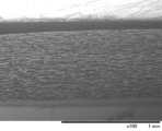
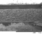
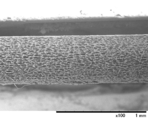
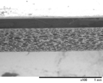
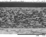
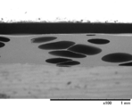
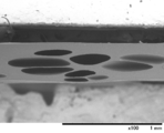
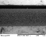
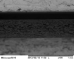
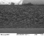
- FIG. 3 is a cross-sectional photograph in the extrusion direction of the foamed sheet obtained in Example 1; These are the width direction cross-sectional photographs of the foamed sheet obtained in Example 1;
- FIG. 3 is a cross-sectional photograph in the extrusion direction of the foamed sheet obtained in Example 1; These are the width direction cross-sectional photographs of the foamed sheet obtained in Example 1;
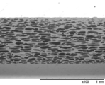
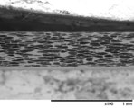
- FIG. 3 is a cross-sectional photograph in the extrusion direction of the foamed sheet obtained in Example 2; These are the width direction cross-sectional photographs of the foamed sheet obtained in Example 2; FIG. 3 is a cross-sectional photograph in the extrusion direction of the foamed sheet obtained in Example 6; These are the width direction cross-section photographs of the foamed sheet obtained in Example 6; FIG. 3 is a cross-sectional photograph in the extrusion direction of the foamed sheet obtained in Example 8; These are the width direction cross-sectional photographs of the foam sheet obtained in Example 8; FIG.
- FIG. 3 is a cross-sectional photograph in the extrusion direction of the foamed sheet obtained in Example 10; These are the cross-sectional photographs of the width direction of the foam sheet obtained in Example 10;
- FIG. 4 is a cross-sectional photograph in the extrusion direction of the foamed sheet obtained in Comparative Example 3; These are the cross-sectional photographs of the width direction of the foam sheet obtained by the comparative example 3;
- FIG. 4 is a cross-sectional photograph in the extrusion direction of the foamed sheet obtained in Comparative Example 5; These are the width direction cross-section photographs of the foamed sheet obtained in Comparative Example 5;
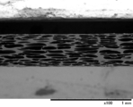
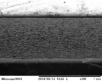
- FIG. 4 is a cross-sectional photograph in the extrusion direction of the foamed sheet obtained in Example 14; These are the cross-sectional photographs of the width direction of the foam sheet obtained in Example 14; FIG. 4 is a cross-sectional photograph in the extrusion direction of the foamed sheet on which the resin layer obtained in Example 17 was laminated; These are the width direction cross-sectional photographs of the foam sheet in which the resin layer obtained in Example 17 was laminated; These are the cross-sectional photographs in the extrusion direction of the foamed sheet on which the resin layer obtained in Example 19 was laminated; These are the width direction cross-sectional photographs of the foam sheet in which the resin layer obtained in Example 19 was laminated; FIG. 4 is a cross-sectional photograph in the extrusion direction of the foamed sheet on which the resin layer obtained in Example 20 was laminated; and These are the width direction cross-sectional photographs of the foam sheet in which the resin layer obtained in Example 20 was laminated.
- the polystyrene resin extruded foam sheet constituting the light reflecting sheet of the present invention is preferably obtained by melt-kneading a polystyrene resin and a foaming agent and extrusion foaming.
- polystyrene-based resin forming the foamed sheet examples include homopolymers of styrene-based monomers, copolymers of styrene-based monomers and other monomers, and two or more of these or one or more of these and other thermoplastic resins. And a mixture thereof.
- the structural unit derived from the styrenic monomer contained in the copolymer or mixture is at least 50% by weight, preferably 60% by weight or more, more preferably 80% by weight or more.
- the styrene monomer is preferably a monomer represented by the following formula (I).
- R represents a hydrogen atom or a methyl group
- Z represents a halogen atom or a methyl group
- p is 0 or an integer of 1 to 3.
- Preferred polystyrene resins include polystyrene, rubber-modified polystyrene (impact polystyrene), styrene-acrylonitrile copolymer, styrene-acrylic acid copolymer, styrene-methacrylic acid copolymer, and styrene-methyl methacrylate copolymer. And styrene-maleic anhydride copolymer, poly- ⁇ -methylstyrene, and a mixture of a polystyrene resin and a polyphenylene ether resin.
- the melt flow rate (hereinafter sometimes referred to as MFR) of the polystyrene-based resin is preferably from 0.1 to 30 g / 10 min, more preferably from 1 to 20 g / 10 min, still more preferably from the viewpoint of facilitating extrusion foaming. Is 2 to 15 g / 10 min.
- the number of bubbles (B) in the thickness direction of the foam sheet is required to be 20 or more.
- the number of bubbles is less than 20, the effect of improving the total reflectance becomes insufficient.
- the number of bubbles in the thickness direction increases, the number of irregular reflections at the bubble interface increases. Therefore, the greater the number of bubbles in the thickness direction, the higher the reflectivity. Therefore, the number of bubbles (B) is more preferably 30 or more, and still more preferably 40 or more.
- the upper limit of the number of bubbles (B) in the thickness direction is approximately 200, preferably 180 because the strength of the resulting foamed sheet is lowered and the production becomes difficult if the number of bubbles is too large. It is.
- the average cell diameter in the thickness direction is 1 to 50 ⁇ m.
- the average cell diameter in the thickness direction exceeds 50 ⁇ m, the total thickness of the foam sheet becomes too thick in order to increase the number of cells in the thickness direction to 20 or more.
- the average cell diameter in the thickness direction is smaller than 1 ⁇ m, it is difficult to produce the foam sheet.
- the average bubble diameter is preferably 2 to 30 ⁇ m, more preferably 3 to 25 ⁇ m, and still more preferably 4 to 20 ⁇ m.
- said bubble structure can be formed by adjusting a cooling rate, a taking-up rate, etc. in the addition amount of a bubble regulator, and the extending
- the bubbles have a flat shape.
- the ratio VD / TD width direction flatness of the average cell diameter (VD) in the thickness direction of the foam sheet to the average cell diameter (TD) in the width direction is preferably 0.08 to 0.5. 0.09 to 0.4 is more preferable, and 0.1 to 0.3 is still more preferable.
- the smaller the ratio VD / TD the flatter in the width direction.
- TD is preferably 5 to 200 ⁇ m, more preferably 10 to 150 ⁇ m, and even more preferably 15 to 100 ⁇ m.
- the ratio VD / MD flatness in the extrusion direction of the average cell diameter (VD) in the thickness direction of the foamed sheet to the average cell diameter (MD) in the extrusion direction is preferably 0.05 to 0.4. 0.07 to 0.3 is more preferable, and 0.1 to 0.25 is still more preferable.
- the smaller the ratio VD / MD the flatter the extrusion direction. Since the bubble shape becomes flat not only in the width direction but also in the extrusion direction, irregular reflection at the bubble interface occurs more efficiently, and the effect of improving the reflectance is obtained.
- MD is preferably 10 to 300 ⁇ m, more preferably 15 to 200 ⁇ m, and still more preferably 20 to 150 ⁇ m.
- the number B of bubbles in the thickness direction, the average bubble diameter VD in the thickness direction, the average bubble diameter TD in the width direction, and the average bubble diameter MD in the extrusion direction are determined as follows.
- a micrograph of the widthwise vertical section of the foamed sheet (vertical section perpendicular to the extrusion direction of the foamed sheet) is taken.
- a straight line is drawn over the entire thickness of the foam sheet in the thickness direction, and the number of bubbles (Nv) intersecting the straight line is counted.
- the above-mentioned measurement of the number of bubbles (Nv) is at least three points (for example, approximately the center position of the width of the foam sheet and two positions on both sides of the center position) that are equally spaced in the width direction of the foam sheet, The test is performed for a total of three positions, two positions apart from the center position by a distance corresponding to 1/3 of the width of each foam sheet.
- the arithmetic average value of the number of counts (Nv) at these measurement points is the number of bubbles B in the thickness direction of the foamed sheet.
- the average cell diameter VD in the thickness direction is determined using the enlarged photograph used in the measurement of the average cell count described above.
- the ratio Ln / Nv is determined from the length (Ln) of the straight line at the measurement location and the number of bubbles (Nv) intersecting the straight line.
- the arithmetic average value of the ratio Ln / Nv at the three measurement points is the average bubble diameter VD in the thickness direction.
- the average bubble diameter TD in the width direction is also determined using the enlarged photograph used for the measurement of the average bubble diameter in the thickness direction.
- a straight line that bisects the thickness of the foam sheet is drawn.
- the length of the straight line in the width direction is a length corresponding to 500 ⁇ m on the enlarged photograph.
- the number Nt of bubbles intersecting the straight line is counted, and (500 ⁇ m / (Nt ⁇ 1)) is calculated from the cant number.
- the arithmetic average value of the calculated values (500 ⁇ m / (Nt ⁇ 1)) at the three measurement points is the average bubble diameter TD in the width direction.
- the average cell diameter MD in the foam sheet extrusion direction is as follows. First, an enlarged photograph is obtained by photographing a microscope of a vertical section of the foam sheet in the extrusion direction (a vertical section parallel to the extrusion direction of the foam sheet and divided in half at the center in the width direction). Photographing is performed at three locations in the cross section (one arbitrary location and two locations spaced apart from each other at equal intervals (for example, 240 mm) in the extrusion direction). A straight line that bisects the thickness of the foam sheet is drawn on each enlarged photograph. The length of the straight line in the extrusion direction is a length corresponding to 500 ⁇ m on the enlarged photograph.
- the number of bubbles (Nm) intersecting the straight line is counted, and (500 ⁇ m / (Nm ⁇ 1)) is calculated from the counted number.
- the arithmetic average value of the calculated values (500 ⁇ m / (Nm ⁇ 1)) at the three measurement points is the average cell diameter MD in the extrusion direction.
- the bubble flatness in the width direction is obtained by dividing the average bubble diameter VD in the thickness direction by the average bubble diameter TD in the width direction (VD / TD). Is obtained by dividing the average cell diameter VD by the average cell diameter MD in the extrusion direction (VD / MD).
- the foam sheet of the present invention contains titanium oxide. Titanium oxide has a relatively high refractive index, has little light absorption, and is suitable for improving the reflectance of the foamed sheet. Furthermore, as the content of titanium oxide per square meter of the foam sheet is increased, the total reflectance on the long wavelength side can be greatly improved with respect to the total reflectance on the short wavelength side. A foamed sheet with a small amount can be obtained.
- the crystal structure of titanium oxide includes an anatase type and a rutile type, but it is preferable to use a rutile type titanium oxide because it has a high refractive index and an excellent effect of improving the reflectance.
- the average particle size of titanium oxide is preferably 100 to 500 nm, more preferably 150 to 400 nm, and still more preferably 200 to 300 nm, from the viewpoint of light shielding properties.
- the foam sheet needs to contain titanium oxide in an amount of A gram (g) per square meter of the foam sheet, where A satisfies the formula 3 ⁇ A ⁇ 70. That is, the content A of titanium oxide per square meter of the foam sheet is 3 to 70 g / m 2 . In other words, the product (A) of the content per unit volume of the foamed sheet of titanium oxide and the thickness of the foamed sheet is 3 to 70 g / m 2 . As the content A of titanium oxide increases, the total reflectance increases, but when it exceeds 70 g / m 2 , the foamed sheet becomes brittle, the lightness is impaired, and the cost is increased.
- the titanium oxide content A is preferably 5 to 50 g / m 2, more preferably 10 to 40 g / m 2 .
- the content A in grams per square meter of the foamed sheet of titanium oxide may be referred to as the content A of titanium oxide.
- the relationship between the content A of titanium oxide and the number B of bubbles in the thickness direction of the foamed sheet satisfies the following formula (3).
- the above formula (3) indicates that the light reflection characteristics of the foamed sheet are related to both the titanium oxide content A and the number of bubbles B in the thickness direction of the foamed sheet. ), The total reflectance of the foamed sheet is reduced, or the reflection unevenness is increased.
- the content A of titanium oxide and the number B of bubbles in the thickness direction satisfy the following expression (4).
- a and B satisfy the following formula (5).
- the thickness of the foamed sheet of the present invention needs to be 0.1 to 3 mm. When the thickness is less than 0.1 mm, the foam sheet is not stiff and handling is not easy. On the other hand, when the thickness exceeds 3 mm, handling properties are deteriorated, for example, a space is required for mounting the foam sheet. From this point of view, the thickness of the foam sheet is preferably 0.15 to 2.0 mm, more preferably 0.2 to 1.5 mm.
- the thickness of the foam sheet is measured with respect to a micrograph of a vertical cross section in the width direction of the foam sheet.
- the measurement is performed at least at three places (for example, approximately the center position of the width of the foam sheet and two positions on both sides of the center position, each being 1/3 of the width of the foam sheet). For a total of three locations, two positions separated from the central position by a distance corresponding to The arithmetic average of the measured values at these measurement points is the thickness of the foam sheet.
- a foam sheet can be formed in the lamination foam sheet which laminated
- Foamed sheet is required to have an apparent density 0.08 ⁇ 0.9g / cm 3.
- the apparent density is lower than 0.08 g / cm 3 , the rigidity is lowered, the stiffness is weakened, and the handling property is lowered.
- the apparent density is higher than 0.9 g / cm 3 , the lightness and rigidity become too high, and the handleability deteriorates.
- ⁇ seat density is preferably 0.1 ⁇ 0.8g / cm 3, more preferably 0.15 ⁇ 0.7g / cm 3.
- the basis weight of the foam sheet is preferably 100 to 450 g / m 2 . If the basis weight is too small, it may be difficult to produce the foam sheet. On the other hand, if the basis weight is too large, the lightness may be lost and the handling may be difficult. From this viewpoint, the basis weight is preferably 105 to 400 g / m 2 , more preferably 110 to 350 g / m 2 , and still more preferably 115 to 300 g / m 2 .
- the foamed sheet of the present invention has the above-mentioned specific apparent density, thickness, number of cells in the thickness direction, average cell diameter in the thickness direction, and contains a specific amount of titanium oxide, and thus is suitably used as a light reflecting sheet. It can be done. Specifically, when the total reflectance at a wavelength of 550 nm is 96.5% or more, it can withstand practical use as a light reflecting sheet. Further, since the difference (MAX ⁇ MIN) between the maximum total reflectance and the minimum total reflectance in the entire visible light region with a wavelength of 450 to 750 nm is 2.0% or less, the reflection unevenness in the wavelength range of 450 to 750 nm is achieved. And the uniformity of the total reflectance in the entire visible light region is excellent.
- the reflectance difference is preferably 1.7% or less, and more preferably 1.5% or less. Further, since the ratio of diffuse reflectance to total reflectance at a wavelength of 550 nm (diffuse reflectance / total reflectance) is 0.95 or more, the specular reflectance is suppressed to a low level. It is suitable for use as. From the above viewpoint, the ratio is preferably 0.96 or more, and more preferably 0.97 or more.
- the foamed sheet of the present invention can be made into a laminated foamed sheet by laminating a resin layer on at least one side thereof.
- a resin layer in addition to the characteristics of the foamed sheet, the laminated foamed sheet has improved and enhanced surface durability and is hardly damaged.
- the resin constituting the resin layer is preferably a polystyrene resin. It is because the adhesiveness of each layer improves by making resin which comprises a foamed layer, and resin which comprises a resin layer into the same kind of resin.
- a polystyrene resin the thing similar to the polystyrene resin which comprises the above-mentioned foamed sheet is mentioned.
- the basis weight of the resin layer is preferably 1 ⁇ 60g / m 2. Within this range, a reflective sheet having good surface properties and excellent durability can be obtained. From this viewpoint, the basis weight is more preferably 3 to 50 g / m 2 , further preferably 5 to 30 g / m 2 .
- additives such as a light diffusing agent can be blended.
- a light diffusing agent is blended in the resin layer, fine irregularities are formed in the resin layer, and occurrence of interference unevenness can be suppressed.
- the resin layer surface is uneven, the slipperiness of the resin layer surface is improved, so the frictional force between the laminated foam sheet and the cooling mandrel is reduced, and the sheet take-up speed can be increased. It becomes easier to reduce the basis weight of the laminated foam sheet.
- the light diffusing agent is preferably organic fine particles that are incompatible with the base resin of the resin layer.
- organic fine particles such as fine particles, fine particles obtained by copolymerizing (meth) acrylic acid ester monomers and styrene monomers.
- the core-shell structure examples include a core layer made of a rubber-like polymer such as a homopolymer or copolymer of an acrylic monomer and covered with a glass-like polymer shell.
- organic fine particles include, for example, “Gantz Pearl” (organic fine particles obtained by polymerizing monomers centering on (meth) acrylic acid ester and styrene) manufactured by Aika Industry Co., Ltd., manufactured by Aika Industry Co., Ltd. “Staffyroid” (organic fine particles consisting of a core formed from a rubber-like polymer having a low Tg made of a homopolymer or copolymer of an acrylic monomer and a shell formed from a polymer having a high Tg), Aika Industry “Zefiac” (polymethacrylic acid ester organic fine particles), “Ganz Pearl SI-020”, and “Staffyroid GSM-1261” manufactured by KK
- the particle size of the light diffusing agent is preferably 1 to 100 ⁇ m, more preferably 2 to 30 ⁇ m. If it is in the said range, while having favorable light diffusibility, it will be excellent in the handleability as a light reflection sheet.
- extrusion foaming that is preferably employed as a method for producing the foamed sheet of the present invention will be described.
- a conventionally well-known technique can be used about the apparatus used for extrusion foaming, and an extrusion method.
- the above-mentioned polystyrene resin, bubble regulator such as talc, titanium oxide, and other additives are supplied to an extruder, heated and melted and kneaded to obtain a molten resin composition, and a physical foaming agent is added to the molten resin composition. Is press-fitted, kneaded, and adjusted to a foamable resin temperature to obtain a foamable resin melt.
- the foamable resin melt is introduced into an annular die and extruded and foamed into the atmosphere to form a cylindrical foam, and then the cylindrical foam is cut open while being pulled along a cylindrical cooling device (mandrel). Thus, a foam sheet is obtained.
- Examples of the air conditioner supplied to the extruder together with the polystyrene resin include inorganic powders such as talc, kaolin, mica, silica, calcium carbonate, barium sulfate, aluminum oxide, clay, bentonite, and diatomaceous earth. be able to.
- talc having a number average median particle size of 0.1 to 20 ⁇ m is preferable, and a particle size of 0.5 to 15 ⁇ m is more preferable.
- the amount of the bubble regulator to be added varies depending on the type of the bubble regulator, but in the present invention, when talc is used in order to form fine bubbles, the content in the resin composition is 1 to It is preferably added so as to be 30% by weight, more preferably 2 to 25% by weight, still more preferably 2.5 to 20% by weight.
- talc when used as a bubble adjusting agent, if the amount added is small, the bubbles become coarse and the reflection efficiency may be lowered. On the other hand, when there is too much addition amount, talc aggregates and there exists a possibility that the bubble refinement
- the foam sheet itself may be colored due to the influence of a small amount of impurities contained in the talc.Therefore, talc with a high degree of whiteness is obtained with less impurities (metallic ions). It is preferable to use it.
- Fluorosurfactants include perfluorobutane sulfonate, perfluoroalkyl group-containing carboxylates, perfluoroalkyl ethylene oxide adducts, perfluoroalkyl group-containing phosphate esters, and perfluoroalkyl group-containing phosphate ester amines. Examples include neutralized products, fluorine-containing group / hydrophilic group-containing oligomers, fluorine-containing group / hydrophilic group / lipophilic group-containing oligomers, and the like. Furthermore, perfluorobutane sulfonate is particularly preferable from the viewpoint of cost.
- the blending amount of the fluorosurfactant is preferably blended so that the content in the resin composition is 0.1 to 5% by weight, and more preferably 0.2 to 2% by weight. If the content is too small, the effect of refining the bubbles cannot be obtained. If the content is too large, there is a possibility that inconvenience such as slip occurs in the extruder.
- various additives such as an antioxidant, an antistatic agent, a crystal nucleating agent, a lubricant, an ultraviolet absorber, and a light stabilizer are within the range not inhibiting the effect of the present invention.
- Fluorescent brighteners, dyes, pigments, processing aids, impact modifiers, fillers, and the like may be added.
- a bubble regulator and the said additive prepare the masterbatch which uses polystyrene resin as a base resin previously, and add the appropriate quantity of the obtained masterbatch.
- the master batch of the foam preparation agent is preferably prepared by adding 25 to 400 parts by weight, more preferably 30 to 250 parts by weight of talc with respect to 100 parts by weight of the polystyrene-based resin when talc is used as the foam regulator. be able to.
- the foaming agent saturated hydrocarbons having 3 to 5 carbon atoms, physical foaming agents such as aliphatic alcohol, carbon dioxide, nitrogen and water, and chemical foaming agents such as sodium hydrogen carbonate can be used.
- foaming agents carbon dioxide and nitrogen are preferably used to make the bubbles finer, and nitrogen is more preferably used because the number of bubbles in the thickness direction can be easily increased.
- the injection amount is preferably 0.01 to 1 part by weight with respect to 100 parts by weight of the resin composition.
- the foam shape can be adjusted by performing the following operations during extrusion foaming in order to form a flat and fine cell structure of the foamed sheet of the present invention.
- adjustment can be made by a method such as increasing the take-up speed with respect to the discharge speed.
- the foam can be adjusted by extruding so as to spread in the width direction.
- the discharge diameter of the annular die and the mandrel that is a cylindrical cooling device can be adjusted by a method of increasing the ratio to the diameter (mandrel diameter / annular die discharge port diameter).
- the foamable resin melt is extruded and foamed from an annular die
- gas is blown onto the surface of the tubular foam in the process of drawing the tubular foam onto the mandrel after exiting the annular die. While cooling, it is preferable to take along the mandrel and to stretch in the extrusion direction and the width direction. By this step, the thickness of the entire foamed sheet can be reduced and the strength of the foamed sheet can be improved. Moreover, the expansion of the bubble diameter in the thickness direction can be suppressed.
- the foam sheet produced by these methods has a cell structure that is flat in the extrusion direction and the width direction with respect to the thickness direction by being stretched and oriented in the extrusion direction and the width direction, and in particular, per unit thickness.
- the number of bubbles is large, and the total reflectance is high. Furthermore, the thickness of the entire foam sheet can be reduced, and the strength of the sheet can be improved.
- the laminated foam sheet can be obtained by laminating a resin layer on one or both sides of the foam sheet.
- a resin layer can be laminated
- the resin layer can be easily laminated on the foamed sheet with few production steps, the resin layer can be firmly fused, and a thin resin layer can be laminated. preferable.
- the coextrusion method an apparatus in which a coextrusion die is attached to an outlet of the foam sheet forming extruder and a resin layer forming extruder is connected to the coextrusion die is used.
- the apparatus for coextrusion such as the said extruder and the annular die for coextrusion, etc. can use the well-known thing conventionally used in the field of coextrusion foaming.
- the raw material is supplied to an extruder for forming a foam sheet, heated and melted and kneaded, and further, a foaming agent is injected to obtain a foamable resin melt.
- a foaming agent is injected to obtain a foamable resin melt.
- a polystyrene resin and, if necessary, an additive such as a light diffusing agent are supplied to an extruder for forming a resin layer, heated and melted and kneaded to obtain a resin melt for forming a resin layer.
- the foam sheet forming resin melt and the resin layer forming resin melt are introduced into a coextrusion die, and the foam melt forming resin melt and the resin layer forming resin are formed in the coextrusion die.
- the melt is merged, and the resin melt for forming the resin layer is laminated on one side or both sides of the resin melt for forming the foam sheet.
- a laminated foamed sheet in which a resin layer is laminated on the surface of the foamed sheet is formed.
- the target laminated foam sheet can be obtained by adjusting the take-up line speed and the blow-up ratio.
- a coextrusion flat die for coextrusion foams into a sheet and laminates, and an annular die for coextrusion uses a cylindrical laminated foam.
- methods such as extrusion foaming, and then cutting the tubular laminated foam along the columnar cooling device while cutting it to obtain a sheet-like laminated foamed sheet.
- the method using an annular die for coextrusion is a preferable method because it can suppress the generation of a corrugated pattern called a corrugate.
- the lamination of the foam sheet-forming resin melt and the resin layer-forming resin melt is preferably performed in an annular die.
- the light reflecting sheet of the present invention can be thermoformed because of its excellent strength.
- the light reflecting sheet of the present invention is made of the polystyrene resin extruded foam sheet, and is installed on the rearmost surface of the liquid crystal TV and reflects light emitted from a light source such as an LED or CCFL to the front surface to use light efficiently. Or mounted on a lighting device such as a fluorescent lamp or an electric signboard, so that the light use efficiency can be increased.
- a light source such as an LED or CCFL
- a lighting device such as a fluorescent lamp or an electric signboard
- Polystyrene resins used in Examples 1 to 18 and Comparative Examples 1 to 5 are PS resin polystyrene resin GX154 (MFR 1.6 g / 10 min; hereinafter abbreviated as GPPS1) and PS Japan polystyrene.
- the weight ratio of resin 679 was 50:50.
- the polystyrene resin used in Example 19 was 100 parts by weight of methacrylic acid copolymerized styrene resin G9001 (MFR 1.7 g / 10 min; hereinafter abbreviated as PSM1) manufactured by PS Japan, and styrene elastomer TR2000 (MFR manufactured by JSR). 13 g / 10 min; hereinafter referred to as SER1) 8.4 parts by weight and PS Japan 679 (MFR 18 g / 10 min; hereinafter referred to as GPPS2) 20 parts by weight.
- PSM1 methacrylic acid copolymerized styrene resin G9001
- MFR manufactured by JSR styrenelastomer TR2000
- 13 g / 10 min; hereinafter referred to as SER1 8.4 parts by weight
- PS Japan 679 MFR 18 g / 10 min; hereinafter referred to as GPPS2
- the polystyrene resin used in Example 20 was 100 parts by weight of poly- ⁇ -methylstyrene resin R431 (MFR 0.2 g / 10 min; hereinafter abbreviated as PS ⁇ ) manufactured by Asahi Kasei Chemicals Corporation, and styrene elastomer TR2000 (manufactured by JSR). It was a mixed resin consisting of 8.4 parts by weight of MFR 13 g / 10 min; hereinafter abbreviated as SER1) and 20 parts by weight of polystyrene resin 679 (MFR 18 g / 10 min; hereinafter abbreviated as GPPS2) manufactured by PS Japan.
- the measurement of melt foot rate (MFR) was performed at a test temperature of 200 ° C. and a load of 5 kg according to the condition H of JIS K 7210.
- Titanium oxide having a rutile structure and an average particle size of 230 nm was used.
- a master batch containing 70 wt% titanium oxide was formed using GPPS2.
- the obtained master batch was used in such an amount that the titanium oxide had a desired blending amount.
- As the fluorosurfactant perfluorobutane sulfonate (manufactured by DIC Corporation, trade name: Megafac F-114) was used.
- a master batch containing 4 wt% of a fluorosurfactant was formed using GPPS2. The obtained master batch was used in such an amount that the desired amount of the fluorosurfactant was obtained.
- talc having an average particle size of 6.9 ⁇ m and whiteness of 98 was used.
- a master batch containing 60 wt% of an air conditioner was formed using GPPS2. The obtained master batch was used in such an amount that the air conditioning agent was in a desired amount.
- GS-2059-U manufactured by Aika Industries (formerly Gantz Kasei) was used as the light diffusing agent.
- a master batch containing 20 wt% of a light diffusing agent was formed using GPPS2. The obtained master batch was used in such an amount that the light diffusing agent was in a desired amount.
- the production apparatus 1 was a tandem type foam layer forming extruder composed of a first extruder having a barrel inner diameter of 65 mm and a second extruder having a barrel inner diameter of 90 mm connected to the first extruder.
- An annular die (lip diameter ⁇ 85 mm) was attached to the outlet of the second extruder.
- the production apparatus 2 is an apparatus for producing a laminated foamed sheet, and is a tandem type foaming device including a first extruder having a barrel inner diameter of 90 mm and a second extruder having a barrel inner diameter of 120 mm connected to the first extruder.
- a sheet forming extruder and a resin layer forming extruder having a barrel inner diameter of 40 mm were provided.
- the foam sheet forming extruder and the resin layer forming extruder were connected to a co-extrusion annular die (lip diameter 110 mm).
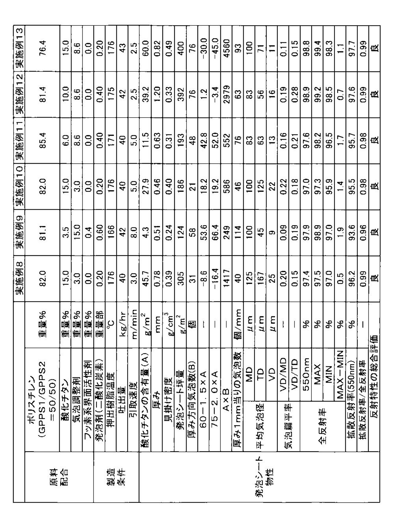
- Example 1 Using the production apparatus 1, the polystyrene resin, titanium oxide, talc, and fluorosurfactant shown in Table 1 were heated, melted, and kneaded in a first extruder to obtain a resin melt. The melt was added with carbon dioxide in the amount shown in Table 1, and then introduced into a second extruder and adjusted to a resin temperature suitable for foaming to obtain a foamable resin melt. The foamable resin melt was introduced into an annular die and extruded as a cylindrical foamed sheet through the die lip of the annular die at a discharge rate of 42 kg / hr.
- the cylindrical foamed sheet was cooled along the cooling mandrel while blowing cooling air having an outer surface side flow rate of 0.5 m 3 / min and an inner surface side of 0.6 m 3 / min.
- the take-up speed of the cylindrical foam sheet is as shown in Table 1.
- the cooled foamed cylindrical sheet was cut in the extrusion direction to obtain two flat foamed sheets having a width of 720 mm.
- the foamed sheet obtained in Example 1 was vacuum-formed using a molding machine manufactured by Asano Laboratories Co., Ltd., FKS-0631-10, at a heater temperature of 350 ° C. and a heating time of 7 seconds ⁇ 1 second.
- the tray was molded into a tray having a portion of 140 ⁇ 105 mm, a bottom portion inside of 120 ⁇ 95 mm, and a depth of 24 mm. Thermoformability was good.
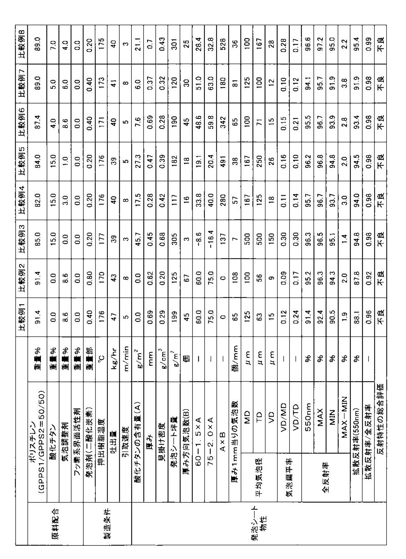
- Examples 2 to 13 and Comparative Examples 1 to 8 For Examples 2 to 13, foaming was carried out in the same manner as in Example 1 except that the formulation and production conditions shown in Tables 1 and 2 were changed, and Comparative Examples 1 to 8 were changed to the formulation and production conditions shown in Table 6. A sheet was obtained.
- Example 14 A foamed sheet was obtained in the same manner as in Example 1 except that nitrogen was used as the foaming agent and the conditions shown in Table 3 were adopted.
- Example 15 A foamed sheet was obtained in the same manner as in Example 1 except that nitrogen was used as the foaming agent and the conditions shown in Table 3 were adopted. The thickness of the obtained foam sheet was 0.29 mm, and the apparent density was 0.69 g / cm 3 .
- Example 16 Using the production apparatus 2, polystyrene, titanium oxide, and talc (bubble regulator) shown in Table 3 were heated, melted, and kneaded to obtain a resin melt. After injecting nitrogen into the melt as shown in Table 3, the melt was adjusted to a resin temperature suitable for foaming in a second extruder to obtain a foamable resin melt. The foamable resin melt was introduced into an annular die for coextrusion and extruded as a cylindrical foamed sheet through the die lip of the annular die at a discharge rate of 97 kg / hr.
- polystyrene, titanium oxide, and talc bubble regulator
- the outer surface of the cylindrical foamed sheet side flow rate 0.5 m 3 / min, while spraying the cooling air of the inner surface side 0.6 m 3 / min, and cooled along a cooling mandrel.
- the take-up speed of the cylindrical foam sheet was as shown in Table 3.
- the cooled foamed cylindrical sheet was cut in the extrusion direction to obtain two flat foam sheets having a width of 1110 mm.
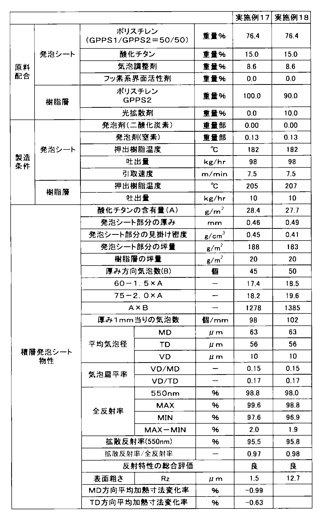
- Example 17 Using the production apparatus 2, a foamable resin melt was produced in the same manner as in Example 16, and introduced into an annular die for coextrusion. At the same time, using a resin layer forming extruder, polystyrene resin (GPPS2) was used as a resin layer forming melt. This was introduced into an annular die for coextrusion at a discharge rate of 10 kg / hr, and the resin layer forming melt was laminated on both the inside and outside of the foamable resin melt flowing in a cylindrical shape in the die. The laminated melt was extruded as a cylindrical foamed sheet through a die lip of an annular die at a discharge rate of 97 kg / hr.
- GPPS2 polystyrene resin
- the cylindrical foamed sheet was cooled along the cooling mandrel while blowing cooling air having an outer surface side flow rate of 0.5 m 3 / min and an inner surface side of 0.6 m 3 / min.
- the take-up speed is as shown in Table 4.
- the cooled cylindrical foam sheet was cut in the extrusion direction to obtain two flat laminated foam sheets having a width of 1110 mm.
- the obtained laminated foam sheet had improved surface scratches and stain resistance more than the single-layer foam sheets of Examples 1 to 16.
- Example 18 A laminated foamed sheet was produced in the same manner as in Example 17 except that the light diffusing agent (GS-2059-U manufactured by Aika Kogyo Co., Ltd.) in the amount shown in Table 4 was added to polystyrene (GPPS2) constituting the resin layer.
- the light diffusing agent GS-2059-U manufactured by Aika Kogyo Co., Ltd.
- GPPS2 polystyrene
- Example 19 A foamed sheet was obtained in the same manner as in Example 1 except that a mixed resin composed of 20 parts by weight of the aforementioned PSM 1100 parts by weight, SER 18.4 parts by weight and GPPS 2 was used as the polystyrene resin (Table 5). .
- a mixed resin composed of 20 parts by weight of the aforementioned PSM 1100 parts by weight, SER 18.4 parts by weight and GPPS 2 was used as the polystyrene resin (Table 5).
- a methacrylic acid copolymerized styrene resin is used, the heating dimensional change rate is lower than when GPPS is used, and the resin can be used for applications requiring high heat resistance.
- Example 20 A foamed sheet was obtained in the same manner as in Example 1 except that a mixed resin composed of 100 parts by weight of PS ⁇ , 18.4 parts by weight of SER and 20 parts by weight of GPPS2 was used as the polystyrene resin (Table 5). .
- PS ⁇ the rate of change in heating dimension is lower than when GPPS is used, and it can be used for applications requiring high heat resistance.
- the amounts of polystyrene resin, titanium oxide, talc, and fluorine-based surfactant shown in Tables 1 to 6 are weight% based on the total amount.
- the amount of the foaming agent is expressed in parts by weight per 100 parts by weight of the polystyrene resin used.
- the foamed sheets obtained in the examples had a specific number B of bubbles in the thickness direction satisfying the formulas (1) to (3) and a content A of a specific amount of titanium oxide. Therefore, it has excellent properties as a reflective sheet.
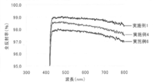
- the total reflectance improves over all visible light from the comparison (FIG. 1) of Example 1, 1 and 4 and Example 6 when the number of bubbles increases.
- FIG. 2 from the comparison between Example 4 and Example 11 (FIG. 2), the total reflectance increases as the content of titanium oxide increases, and in particular, the total reflection on the long wavelength side. It can be seen that the rate improvement effect is large.
- FIG. 1 the foamed sheets obtained in the examples had a specific number B of bubbles in the thickness direction satisfying the formulas (1) to (3) and a content A of a specific amount of titanium oxide. Therefore, it has excellent properties as a reflective sheet.
- the total reflectance improves over all visible light from the comparison (FIG. 1) of Example 1, 1 and 4 and Example 6 when the number of bubbles increases.
- FIG. 2 from the
- the measurement result of total reflectance for the foamed sheets of Examples 1, 4 and 6 having different numbers of bubbles in the thickness direction is the wavelength (nm) on the horizontal axis, and the total reflectance (%) is on the vertical axis. It is the graph shown as.
- FIG. 2 shows the measurement results of total reflectance for the foamed sheets of Examples 4 and 11 having different titanium oxide contents, with the wavelength (nm) on the horizontal axis and the total reflectance (%) on the vertical axis. It is a graph. Extrusion direction and width direction cross-sectional photographs of the foamed sheets obtained in Examples 1, 2, 6, 8, 10, 14, 17, 19 and 20 and Comparative Examples 3 and 5 are shown in FIGS.
- Comparative Example 1 is an example in which no titanium oxide is added. If titanium oxide is not added, the total reflectance (550 nm) will be less than 96.5%.
- Comparative Example 2 is an example in which the number of bubbles in the thickness direction was increased without adding titanium oxide. Even if the number of bubbles is large, if titanium oxide is not added, the total reflectance (550 nm) is less than 96.5%. Also, the reflectance ratio is less than 0.95.
- Comparative Example 3 is an example in which there are extremely few bubbles in the thickness direction. Even if the titanium oxide content (A) satisfies the requirements of the present invention, the total reflectance (550 nm) is less than 96.5%.
- Comparative Examples 4 and 5 are examples in which the number of bubbles in the thickness direction is larger than that of Comparative Example 3. However, if the number of bubbles in the thickness direction is outside the range defined by the present invention, the effect of improving the reflectance is low. Comparative Examples 6 to 8 are examples that do not satisfy Formula (3). In this case, the reflection unevenness is large, and the difference (MAX ⁇ MIN) between the maximum value and the minimum value of the total reflectance in the wavelength range of 450 to 750 nm exceeds 2.0%.
- ⁇ Basis weight of foam sheet (g / m 2 )> A test piece having a length of 10 cm long ⁇ 10 cm wide ⁇ foamed sheet was cut out at equal intervals in the width direction over the entire width of the foamed sheet, and the weight (g) of the test piece was measured.
- the basis weight of the foamed sheet was obtained by dividing the weight of the test piece by its area and then converting the unit.
- the basis weight of the entire laminated foamed sheet was measured by the same method as described above.
- the basis weight of the resin laminated portion was calculated from the discharge amount of the resin layer laminating extruder, the sheet take-up speed, and the sheet width.
- the basis weight of the foam sheet was obtained by subtracting the basis weight of the resin laminate from the basis weight of the laminated foam sheet.
- Tianium oxide content A (g / m 2 )>
- the titanium oxide content A of the foamed sheet was calculated from the basis weight of the foamed sheet and the amount of titanium oxide used.
- ⁇ Average number of bubbles B in the thickness direction> The number of bubbles in the thickness direction of the foamed sheet was determined by the method described above. The number of bubbles was measured at three locations at equal intervals in the width direction of the foamed sheet (a total of three locations 240 mm away from the central portion and both ends from the central portion). In the case of the laminated foam sheet, the measurement was similarly performed on the foam sheet portion.
- the average cell diameter in the thickness direction and the average cell diameter in the width direction were measured by the methods described above using the enlarged photographs used for the measurement of the average number of cells in the thickness direction.
- the average cell diameter in the extrusion direction was determined separately by the method described above.
- the number of bubbles was measured at three locations on the cross section in the extrusion direction of the foamed sheet (any one location and two locations spaced apart from each other at equal intervals (240 mm) in the extrusion direction). In the case of a laminated foam sheet, the measurement was made in the same manner for the foam sheet portion.
- VD / MD bubble flatness and VD / TD bubble flatness were calculated by the above method from the average bubble diameter.
- Total reflectance, diffuse reflectance> The total light reflectance was measured according to JIS K7105-1981, total light reflectance measurement method A. Specifically, three test pieces were cut out from three locations of the foam sheet (a central portion in the width direction and two positions separated from the central portion by 240 mm in the opposite direction of the width direction). For the total reflectance measurement, the surface (mandrel contact surface) of each test piece was measured using an ultraviolet-visible spectrophotometer (Shimadzu, UV-2450) and an integrating sphere sample stand (Shimadzu, ISR-2200).
- the reflectance at an incident angle of 8 degrees in the wavelength range of 450 to 750 nm was measured every 0.5 nm, and the arithmetic average value of the values obtained for the three sheets was taken as the total reflectance (%).
- the total reflectance is a relative value with the reflectance of barium sulfate (Merck, DIN 5033, white standard) as 100%.
- the diffuse reflectance was measured using the same apparatus as that for measuring the total reflectance, with an incident angle of 0 degree.
- surface is an arithmetic average value of the total reflectance in wavelength 550nm about three test pieces.
- the total reflectance (MAX) (maximum value of total reflectance) in the table is an arithmetic average value of the maximum reflectance values in the wavelength range of 450 to 750 nm for the three test pieces.
- Total reflectance (MIN) (minimum value of total reflectance) is an arithmetic average value of minimum values of reflectance in a wavelength range of 450 to 750 nm for three test pieces.
- the total reflectance (MAX-MIN) is obtained from the difference between the maximum value and the minimum value of the total reflectance.
- the diffuse reflectance / total reflectance is the ratio of the diffuse reflectance at 550 nm to the total reflectance at 550 nm.
- the laminated foam sheet measured similarly about the sheet
Landscapes
- Chemical & Material Sciences (AREA)
- Engineering & Computer Science (AREA)
- Materials Engineering (AREA)
- Medicinal Chemistry (AREA)
- Organic Chemistry (AREA)
- Mechanical Engineering (AREA)
- Health & Medical Sciences (AREA)
- Chemical Kinetics & Catalysis (AREA)
- Polymers & Plastics (AREA)
- Physics & Mathematics (AREA)
- Optics & Photonics (AREA)
- General Physics & Mathematics (AREA)
- Inorganic Chemistry (AREA)
- Manufacture Of Porous Articles, And Recovery And Treatment Of Waste Products (AREA)
- Laminated Bodies (AREA)
- Optical Elements Other Than Lenses (AREA)
- Compositions Of Macromolecular Compounds (AREA)
- Extrusion Moulding Of Plastics Or The Like (AREA)
Abstract
Description
発明の背景
3 ≦ A ≦ 70 (1)
B ≧ 20 (2)
B ≧ 60-1.5×A (3)
が提供される。
第3の態様において、本発明は、前記酸化チタンがルチル型結晶構造を有する、上記第1または第2の態様の光反射シートを提供する。
第4の態様において、本発明は、前記ポリスチレン系樹脂発泡シートの坪量が100~450g/m2である、上記第1~第3の態様のいずれかの光反射シートが提供される。
第5の態様において、本発明は、前記発泡シートが、フッ素系界面活性剤を含有する、上記第1~第4の態様のいずれかの光反射シートを提供する。
第6の態様において、本発明は、前記発泡シートの少なくとも片方の面に積層された樹脂層を更に含む、上記第1~第5の態様のいずれかの光反射シートを提供する。
第7の態様において、本発明は、前記樹脂層の坪量が3~30g/m2である、上記第6の態様の光反射シートを提供する。
第8の態様において、本発明は、前記発泡シートが押出発泡により形成されたものである第1~第7の態様のいずれかの光反射シートを提供する。

なお、本明細書において、酸化チタンの発泡シート1平方メートル当たりの含有量グラム数Aを、酸化チタンの含有量Aということがある。
B≧60-1.5×A ・・・(3)
上記式(3)は、発泡シートの光反射特性が前記発泡シートの酸化チタンの含有量Aと、厚み方向の気泡数Bとの両方に関連していることを示しており、上記式(3)を満足しない場合には、発泡シートの全反射率が低下したり、反射ムラが大きくなったりする。前記観点から、酸化チタンの含有量Aと、厚み方向の気泡数Bは、下式(4)を満足することがより好ましい。
B≧75-2.0×A ・・・(4)
更に、AとBは下式(5)を満足することがさらに好ましい。
A×B≧750 ・・・(5)
(1)実施例1~18、比較例1~5において用いたポリスチレン系樹脂は、PSジャパン社製ポリスチレン樹脂GX154(MFR 1.6g/10分;以下GPPS1と略す)と、PSジャパン社製ポリスチレン樹脂679(MFR 18g/10分:以下GPPS2と略す)との重量比50:50混合樹脂であった。
実施例19において用いたポリスチレン系樹脂は、PSジャパン社製 メタクリル酸共重合スチレン系樹脂G9001(MFR 1.7g/10分;以下PSM1と略す)100重量部、JSR社製 スチレン系エラストマー TR2000(MFR 13g/10分;以下SER1と略す)8.4重量部、及びPSジャパン社製 679(MFR 18g/10分;以下GPPS2と略す)20重量部からなる混合樹脂であった。
実施例20において用いたポリスチレン系樹脂は、旭化成ケミカルズ社製 ポリ-α-メチルスチレン系樹脂 R431(MFR 0.2g/10分;以下PSαと略す)100重量部、JSR社製 スチレン系エラストマー TR2000(MFR 13g/10分; 以下SER1と略す)8.4重量部、及びPSジャパン社製ポリスチレン樹脂679(MFR 18g/10分;以下GPPS2と略す)20重量部からなる混合樹脂であった。
なお、メルトフトーレイト(MFR)の測定は、JIS K 7210の条件Hに準じて、試験温度200℃、荷重5kgで行なった。
(3)フッ素系界面活性剤としては、パーフルオロブタンスルホン酸塩(DIC社製、商品名メガファックF-114)を用いた。フッ素系界面活性剤を4wt%含むマスターバッチをGPPS2を用いて形成した。得られたマスターバッチを、フッ素系界面活性剤が所望される配合量となるような量用いた。
(4)気泡調整剤としては、平均粒径6.9μm、白色度98のタルクを用いた。気泡調整剤を60wt%含むマスターバッチをGPPS2を用いて形成した。得られたマスターバッチを気泡調整剤が所望される配合量となるような量用いた。
(5)光拡散剤としては、GS-2059-U(アイカ工業(旧ガンツ化成)社製)を用いた。光拡散剤を20wt%含むマスターバッチをGPPS2を用いて形成した。得られたマスターバッチを光拡散剤が所望される配合量となるような量用いた。
製造装置1は、バレル内径65mmの第一押出機と、第一押出機に接続されたバレル内径90mmの第二押出機とからなるタンデム型の発泡層形成用押出機であった。該第二押出機の出口に環状ダイ(リップ径φ85mm)が取付けられた。
(2)製造装置2
製造装置2は、積層発泡シートを製造するための装置であり、バレル内径90mmの第一押出機と、第一押出機に接続されたバレル内径120mmの第二押出機とからなるタンデム型の発泡シート形成用押出機と、バレル内径40mmの樹脂層形成用押出機とを備えた。発泡シート形成用押出機と樹脂層形成用押出機とは共押出用環状ダイ(リップ径φ110mm)に接続された。
前記製造装置1を用い、第一押出機にて、表1に示すポリスチレン樹脂、酸化チタン、タルク、フッ素系界面活性剤を加熱、溶融、混練して樹脂溶融物を得た。この溶融物を、それに二酸化炭素を表1中に示す量加えた後、第二押出機に導入し発泡に適した樹脂温度に調整して、発泡性樹脂溶融物を得た。発泡性樹脂溶融物を環状ダイ中に導入し、環状ダイのダイリップを通して吐出量42kg/hrで筒状発泡シートとして押出した。次いで、筒状発泡シートを、外面側流量0.5m3/min、内面側0.6m3/minの冷却エアを吹き付けながら、冷却マンドレルに沿わせて冷却した。筒状発泡シートの引取り速度は表1に示した通りである。冷却した発泡筒状シートを押出し方向に切断して、2枚の幅720mmの平坦なシート状の発泡シートを得た。
実施例2~13については表1および表2に示す配合、製造条件に変更し、比較例1~8については表6示す配合、製造条件に変更した以外は、実施例1と同様にして発泡シートを得た。
発泡剤に窒素を用い、表3に示す条件を採用したこと以外は、実施例1と同様にして発泡シートを得た。
発泡剤に窒素を用い、表3に示す条件を採用したこと以外は、実施例1と同様にして発泡シートを得た。
得られた発泡シートの厚みは0.29mm、見かけ密度は0.69g/cm3であった。
製造装置2を使用し、表3に示すポリスチレン、酸化チタン、タルク(気泡調整剤)を加熱、溶融、混練して樹脂溶融物を得た。この溶融物を、それに窒素を表3中に示す量注入した後、第二押出機中で発泡に適した樹脂温度に調整して、発泡性樹脂溶融物を得た。発泡性樹脂溶融物を共押出用環状ダイ中に導入し、環状ダイのダイリップを通して吐出量97kg/hrで筒状発泡シートとして押出した。次いで、筒状発泡シートを外面側流量0.5m3/min、内面側0.6m3/minの冷却エアを吹き付けながら、冷却マンドレルに沿わせて冷却した。筒状発泡シートの引取り速度は表3に記載の通りであった。冷却した発泡筒状シートを押出し方向に切断して、2枚の幅1110mmの平坦な発泡シートを得た。
製造装置2を使用し、発泡性樹脂溶融物を実施例16と同様に製造し、共押出用環状ダイ中に導入した。同時に樹脂層形成用押出機を用いて、ポリスチレン系樹脂(GPPS2)を樹脂層形成用溶融物とした。これを吐出量10kg/hrで共押出用環状ダイ中に導入し、該ダイ中で、円筒状に流動する発泡性樹脂溶融物の内側と外側の両面に樹脂層形成用溶融物を積層した。積層された溶融物を環状ダイのダイリップを通して吐出量97kg/hrで筒状発泡シートとして押出た。次いで、筒状発泡シートを外面側流量0.5m3/min、内面側0.6m3/minの冷却エアを吹き付けながら、冷却マンドレルに沿わせて冷却した。引取り速度は表4に記載の通りである。冷却した筒状発泡シートを、押出し方向に切断して、2枚の幅1110mmの平坦な積層発泡シートを得た。得られた積層発泡シートは実施例1~16までの単層の発泡シートよりも、表面の傷や汚れの付き難さが向上したものであった。
樹脂層を構成するポリスチレン(GPPS2)に、表4に示す量の光拡散剤(アイカ工業社製GS-2059-U)を添加した以外、実施例17と同様に積層発泡シートを製造した。
ポリスチレン系樹脂として、前述のPSM1100重量部、SER18.4重量部、およびGPPS2を20重量部からなる混合樹脂を用いたこと以外は、実施例1と同様にして発泡シートを得た(表5)。メタクリル酸共重合スチレン系樹脂を用いると、GPPSを用いた場合よりも加熱寸法変化率が低下し、高い耐熱性を要求される用途に使用可能なものとなる。
ポリスチレン系樹脂として、前述のPSα100重量部、SER18.4重量部、およびGPPS2を20重量部からなる混合樹脂を用いたこと以外は、実施例1と同様にして発泡シートを得た(表5)。PSαを用いると、GPPSを用いた場合よりも加熱寸法変化率が低下し、高い耐熱性を要求される用途に使用可能なものとなる。なお、表1~6に示したポリスチレン樹脂、酸化チタン、タルク、フッ素系界面活性の使用量は、これらの合計量に基づく重量%である。発泡剤の量は使用したポリスチレン系樹脂100重量部あたりの重量部で表している。
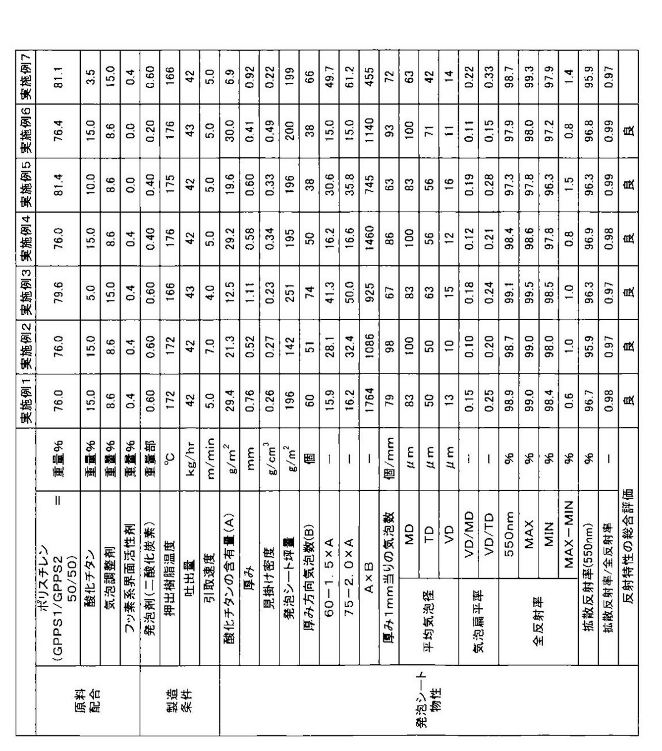


なお、図1は、厚み方向の気泡数が異なる実施例1、4および6の発泡シートについての全反射率の測定結果を波長(nm)を横軸とし、全反射率(%)を縦軸として示したグラフである。図2は、酸化チタンの含有量が異なる実施例4および11の発泡シートについての全反射率の測定結果を、波長(nm)を横軸とし、全反射率(%)を縦軸として示したグラフである。
実施例1,2,6,8,10,14,17,19および20、ならびに比較例3および5で得られた発泡シートの押出方向および幅方向断面写真を図3~24に示す。
<発泡シートの厚み>
発泡シートの厚みは、前記の方法により測定した。
発泡シートの全幅にわたって、幅方向に等間隔に、縦10cm×横10cm×発泡シートの厚みの試験片を切り出し、該試験片の重量(g)を測定した。発泡シートの坪量は、試験片の重量をその面積で除し、次いで単位換算することで求めた。なお、積層発泡シートの場合には、まず、前述と同様の方法にて積層発泡シート全体の坪量を測定した。一方、樹脂層積層用押出機の吐出量とシートの引取り速度、及びシートの幅から樹脂積層部の坪量を算出した。そして、発泡シートの坪量は、積層発泡シートの坪量から樹脂積層部の坪量を減じて求めた。
発泡シートの見掛け密度は、発泡シートの坪量を、発泡シートの厚みにより除し、次いで単位換算することにより求めた。
発泡シートの酸化チタン含有量Aは、前記発泡シートの坪量と、酸化チタン使用量より計算にて求めた。
発泡シートの厚み方向の気泡数は、前述の方法により求めた。なお、気泡数の測定は、発泡シートの幅方向に等間隔に3箇所(シート中央部及び中央部より両端側に240mm離れた計3箇所)について行った。積層発泡シートの場合には、発泡シート部分について同様に測定した。
厚み方向平均気泡径、幅方向平均気泡径は、前記厚み方向の平均気泡数の測定に用いた、各々の拡大写真を使用して、前述の方法により行った。押出方向の平均気泡径は、別途、前述の方法により求めた。なお、気泡数の測定は、発泡シートの押出方向断面上の3箇所(任意の1箇所と、該箇所から押出方向に互いに反対方向に等間隔(240mm)離れた2箇所)について行った。なお、積層発泡シートの場合には、発泡シート部分について同様に測定した。
VD/MD気泡扁平率、VD/TD気泡扁平率は、前記平均気泡径から前記方法により算出した。
JIS K7105-1981の全光線反射率測定法Aに準拠して求めた。具体的には、発泡シートの3箇所(幅方向の中央部及び該中央部より幅方向の反対方向に240mm離れた2つの位置)から3つの試験片を切り出した。全反射率測定は、各試験片の表面(マンドレル接触面)を紫外可視分光光度計(島津製作所製、UV-2450)と、積分球試料台(島津製作所製、ISR-2200)とを使用し0.5nm毎に波長450~750nmの範囲の、入射角8度における反射率を測定し、3枚のシートについて得られた値の算術平均値を全反射率(%)とした。なお、該全反射率は、硫酸バリウム(Merck社製、DIN5033、白色標準)の反射率を100%とした相対値である。
拡散反射率の測定は、前記全反射率の測定と同じ装置を用い、入射角0度として測定を行った。
なお、表中の全反射率(550nm)は、3つの試験片についての波長550nmにおける全反射率の算術平均値である。表中の全反射率(MAX)(全反射率の最大値)は、3つの試験片についての波長450~750nmの範囲における反射率の最大値の算術平均値である。全反射率(MIN)(全反射率の最小値)は、3つの試験片についての波長450~750nmの範囲における反射率の最小値の算術平均値である。全反射率(MAX-MIN)は、上記全反射率の最大値と最小値との差から求められる。拡散反射率/全反射率は、550nmにおける拡散反射率の550nmにおける全反射率に対する比)である。
なお、積層発泡シートは、樹脂層が積層された状態でのシートについて、同様に測定を行った。
光反射特性の総合評価は、以下の(i)~(iii)の3つ全ての基準に合格した場合のみ、光反射性が良好であるとして判断して行った。(i)~(iii)の基準の一つ又はそれ以上満たされない場合は光反射性が不良として判断した。
基準(i):550nmにおける全反射率が96.5%以上である。該全反射率が96.5%であれば、発泡シートは光反射シートとして実用可能である。
基準(ii):450~750nmの波長範囲における全反射率の最大値と、最小値との差(MAX-MIN)が2.0%以下である。(MAX-MIN)が2.0%以下であれば、発泡シートは反射ムラが少なく、450~750nmの波長範囲において、安定した光反射性能を発揮できる。
基準(iii):550nmにおける拡散反射率の550nmにおける全反射率に対する比(拡散反射率/全反射率)が、0.95以上である。この比が0.95より小さくなると、発泡シートの鏡面反射率が高まり、例えば、発泡シートを液晶TVに実装した場合に視野角が狭くなるなどの不具合が生じ易くなる。
Claims (8)
- 見掛け密度0.08~0.9g/cm3および厚み0.1~3mmを有するポリスチレン系樹脂発泡シートから構成される光反射シートであって、
該発泡シートが酸化チタンを該発泡シート1平方メートル当たりAグラムの量で含有するとともに、その厚み方向の平均気泡径1~50μmおよびその厚み方向の気泡数Bを有し、
AとBが下式(1)~(3)を満足する光反射シート。
3 ≦ A ≦ 70 (1)
B ≧ 20 (2)
B ≧ 60-1.5×A (3)
- 前記酸化チタンの含有量Aが10~50g/m2、及び/又は前記気泡数Bが35個以上である、請求項1に記載の光反射シート。
- 前記酸化チタンがルチル型結晶構造を有する、請求項1または請求項2に記載の光反射シート。
- 前記ポリスチレン系樹脂発泡シートの坪量が100~450g/m2である、請求項1~請求項3のいずれかに記載の光反射シート。
- 前記発泡シートが、フッ素系界面活性剤を含有する、請求項1~請求項4のいずれかに記載の光反射シート。
- 前記発泡シートの少なくとも片方の面に積層された樹脂層を更に含む、請求項1~請求項5のいずれかに記載の光反射シート。
- 前記樹脂層の坪量が3~30g/m2である、請求項6に記載の光反射シート。
- 前記発泡シートが押出発泡により形成されたものである請求項1~請求項7のいずれかに記載の光反射シート。
Priority Applications (3)
| Application Number | Priority Date | Filing Date | Title |
|---|---|---|---|
| CN201380038846.8A CN104471447B (zh) | 2012-07-23 | 2013-07-18 | 光反射片 |
| JP2013550680A JP5645292B2 (ja) | 2012-07-23 | 2013-07-18 | 光反射シート |
| KR1020147034705A KR101563104B1 (ko) | 2012-07-23 | 2013-07-18 | 광 반사 시트 |
Applications Claiming Priority (4)
| Application Number | Priority Date | Filing Date | Title |
|---|---|---|---|
| JP2012-162987 | 2012-07-23 | ||
| JP2012162987 | 2012-07-23 | ||
| JP2012-178297 | 2012-08-10 | ||
| JP2012178297 | 2012-08-10 |
Publications (1)
| Publication Number | Publication Date |
|---|---|
| WO2014017367A1 true WO2014017367A1 (ja) | 2014-01-30 |
Family
ID=49997181
Family Applications (1)
| Application Number | Title | Priority Date | Filing Date |
|---|---|---|---|
| PCT/JP2013/069473 Ceased WO2014017367A1 (ja) | 2012-07-23 | 2013-07-18 | 光反射シート |
Country Status (4)
| Country | Link |
|---|---|
| JP (1) | JP5645292B2 (ja) |
| KR (1) | KR101563104B1 (ja) |
| CN (1) | CN104471447B (ja) |
| WO (1) | WO2014017367A1 (ja) |
Cited By (2)
| Publication number | Priority date | Publication date | Assignee | Title |
|---|---|---|---|---|
| JP2017122184A (ja) * | 2016-01-08 | 2017-07-13 | デンカ株式会社 | スチレン系樹脂発泡シートとその製造方法及び食品包装容器 |
| JP2020111060A (ja) * | 2016-02-05 | 2020-07-27 | 大日本印刷株式会社 | 内装用シート、部屋、乗り物 |
Families Citing this family (1)
| Publication number | Priority date | Publication date | Assignee | Title |
|---|---|---|---|---|
| JP7834540B2 (ja) * | 2022-03-31 | 2026-03-24 | 株式会社ジェイエスピー | 発泡シートの製造方法 |
Citations (5)
| Publication number | Priority date | Publication date | Assignee | Title |
|---|---|---|---|---|
| JP2002194129A (ja) * | 2000-12-22 | 2002-07-10 | Kanegafuchi Chem Ind Co Ltd | スチレン系樹脂押出発泡体およびその製造方法 |
| JP2004196907A (ja) * | 2002-12-17 | 2004-07-15 | Jsp Corp | ポリスチレン系樹脂押出発泡板の製造方法及びポリスチレン系樹脂押出発泡板 |
| JP2009256426A (ja) * | 2008-04-14 | 2009-11-05 | Jsp Corp | スチレン系樹脂押出発泡板 |
| JP2010145908A (ja) * | 2008-12-22 | 2010-07-01 | Furukawa Electric Co Ltd:The | 光反射シートおよびその製造方法 |
| JP2011075890A (ja) * | 2009-09-30 | 2011-04-14 | Sekisui Plastics Co Ltd | 光拡散シート、光拡散シートの製造方法、および発光装置 |
Family Cites Families (7)
| Publication number | Priority date | Publication date | Assignee | Title |
|---|---|---|---|---|
| JP4923378B2 (ja) | 2003-05-16 | 2012-04-25 | 東レ株式会社 | 光反射フィルムおよびその製造方法 |
| JP4566549B2 (ja) * | 2003-11-28 | 2010-10-20 | 株式会社カネカ | 高断熱性スチレン系樹脂発泡体およびその製造方法 |
| US20090068402A1 (en) * | 2005-04-19 | 2009-03-12 | Kenichi Yoshida | Foamed Sheet for Reflector, Reflector, and Method for Producing Foamed Sheet for Reflector |
| CN100543500C (zh) * | 2005-04-19 | 2009-09-23 | 积水化成品工业株式会社 | 反射板用发泡片材、反射板及反射板用发泡片材的制造方法 |
| KR101132503B1 (ko) | 2005-09-14 | 2012-04-02 | 코오롱인더스트리 주식회사 | 반사시트 |
| JP2008088207A (ja) * | 2006-09-29 | 2008-04-17 | Asahi Kasei Chemicals Corp | ポリトリメチレンテレフタレート樹脂組成物発泡シート及びその製造方法 |
| JP2011170295A (ja) * | 2010-02-22 | 2011-09-01 | Sekisui Plastics Co Ltd | 光反射板 |
-
2013
- 2013-07-18 JP JP2013550680A patent/JP5645292B2/ja not_active Expired - Fee Related
- 2013-07-18 KR KR1020147034705A patent/KR101563104B1/ko not_active Expired - Fee Related
- 2013-07-18 CN CN201380038846.8A patent/CN104471447B/zh not_active Expired - Fee Related
- 2013-07-18 WO PCT/JP2013/069473 patent/WO2014017367A1/ja not_active Ceased
Patent Citations (5)
| Publication number | Priority date | Publication date | Assignee | Title |
|---|---|---|---|---|
| JP2002194129A (ja) * | 2000-12-22 | 2002-07-10 | Kanegafuchi Chem Ind Co Ltd | スチレン系樹脂押出発泡体およびその製造方法 |
| JP2004196907A (ja) * | 2002-12-17 | 2004-07-15 | Jsp Corp | ポリスチレン系樹脂押出発泡板の製造方法及びポリスチレン系樹脂押出発泡板 |
| JP2009256426A (ja) * | 2008-04-14 | 2009-11-05 | Jsp Corp | スチレン系樹脂押出発泡板 |
| JP2010145908A (ja) * | 2008-12-22 | 2010-07-01 | Furukawa Electric Co Ltd:The | 光反射シートおよびその製造方法 |
| JP2011075890A (ja) * | 2009-09-30 | 2011-04-14 | Sekisui Plastics Co Ltd | 光拡散シート、光拡散シートの製造方法、および発光装置 |
Cited By (2)
| Publication number | Priority date | Publication date | Assignee | Title |
|---|---|---|---|---|
| JP2017122184A (ja) * | 2016-01-08 | 2017-07-13 | デンカ株式会社 | スチレン系樹脂発泡シートとその製造方法及び食品包装容器 |
| JP2020111060A (ja) * | 2016-02-05 | 2020-07-27 | 大日本印刷株式会社 | 内装用シート、部屋、乗り物 |
Also Published As
| Publication number | Publication date |
|---|---|
| CN104471447B (zh) | 2016-03-30 |
| KR101563104B1 (ko) | 2015-10-23 |
| CN104471447A (zh) | 2015-03-25 |
| JP5645292B2 (ja) | 2014-12-24 |
| KR20150000905A (ko) | 2015-01-05 |
| JPWO2014017367A1 (ja) | 2016-07-11 |
Similar Documents
| Publication | Publication Date | Title |
|---|---|---|
| JP4005123B2 (ja) | 反射板用発泡シート、反射板及び反射板用発泡シートの製造方法 | |
| CN1922509B (zh) | 用于平板显示的漫射膜 | |
| JP2010222566A (ja) | 樹脂成形体およびその製造方法 | |
| JP5645292B2 (ja) | 光反射シート | |
| JP5006891B2 (ja) | アクリル系樹脂フィルムの製造方法及びアクリル系樹脂フィルム | |
| WO2006064907A1 (ja) | 光反射体およびそれを用いた面光源装置 | |
| CN100543500C (zh) | 反射板用发泡片材、反射板及反射板用发泡片材的制造方法 | |
| KR102001119B1 (ko) | 액정 디스플레이 반사판용 적층형 백색 폴리에스테르 필름 | |
| JP2015138151A (ja) | 光反射シート | |
| JP2012027382A (ja) | 反射板 | |
| JP2010042598A (ja) | 帯電防止性多層シートの製造方法 | |
| JP5942106B2 (ja) | ポリオレフィン樹脂製透明シート | |
| JP2011075890A (ja) | 光拡散シート、光拡散シートの製造方法、および発光装置 | |
| JP2009109596A (ja) | 反射シート | |
| JP4866075B2 (ja) | 光反射体およびそれを用いた面光源装置 | |
| JP2016194548A (ja) | 光反射シート | |
| JP2010070608A (ja) | 光学用アクリルフィルム、導光板およびバックライトユニット | |
| JP2018034380A (ja) | 樹脂シート | |
| TW202108381A (zh) | 多層薄膜及其製造方法,以及捲繞體 | |
| JP2014223784A (ja) | フィルム | |
| JP2014038171A (ja) | 異方性光拡散積層体及びプロジェクタースクリーン | |
| JP5205000B2 (ja) | 反射シート | |
| KR102001118B1 (ko) | 액정 디스플레이 반사판용 적층형 백색 폴리에스테르 필름 | |
| KR20130108290A (ko) | 광반사체, 조명 기구, 전식 간판 및 면광원 장치 | |
| JP2015069020A (ja) | 白色反射フィルム |
Legal Events
| Date | Code | Title | Description |
|---|---|---|---|
| WWE | Wipo information: entry into national phase |
Ref document number: 201380038846.8 Country of ref document: CN |
|
| ENP | Entry into the national phase |
Ref document number: 2013550680 Country of ref document: JP Kind code of ref document: A |
|
| 121 | Ep: the epo has been informed by wipo that ep was designated in this application |
Ref document number: 13823389 Country of ref document: EP Kind code of ref document: A1 |
|
| ENP | Entry into the national phase |
Ref document number: 20147034705 Country of ref document: KR Kind code of ref document: A |
|
| NENP | Non-entry into the national phase |
Ref country code: DE |
|
| 122 | Ep: pct application non-entry in european phase |
Ref document number: 13823389 Country of ref document: EP Kind code of ref document: A1 |