WO2014017263A1 - ガラス製品の製造方法およびガラス製品製造装置 - Google Patents
ガラス製品の製造方法およびガラス製品製造装置 Download PDFInfo
- Publication number
- WO2014017263A1 WO2014017263A1 PCT/JP2013/068132 JP2013068132W WO2014017263A1 WO 2014017263 A1 WO2014017263 A1 WO 2014017263A1 JP 2013068132 W JP2013068132 W JP 2013068132W WO 2014017263 A1 WO2014017263 A1 WO 2014017263A1
- Authority
- WO
- WIPO (PCT)
- Prior art keywords
- workpiece
- glass product
- glass
- temperature
- pulse current
- Prior art date
- Legal status (The legal status is an assumption and is not a legal conclusion. Google has not performed a legal analysis and makes no representation as to the accuracy of the status listed.)
- Ceased
Links
Images



Classifications
-
- C—CHEMISTRY; METALLURGY
- C03—GLASS; MINERAL OR SLAG WOOL
- C03B—MANUFACTURE, SHAPING, OR SUPPLEMENTARY PROCESSES
- C03B23/00—Re-forming shaped glass
- C03B23/0086—Heating devices specially adapted for re-forming shaped glass articles in general, e.g. burners
-
- C—CHEMISTRY; METALLURGY
- C03—GLASS; MINERAL OR SLAG WOOL
- C03B—MANUFACTURE, SHAPING, OR SUPPLEMENTARY PROCESSES
- C03B11/00—Pressing molten glass or performed glass reheated to equivalent low viscosity without blowing
- C03B11/12—Cooling, heating, or insulating the plunger, the mould, or the glass-pressing machine; cooling or heating of the glass in the mould
- C03B11/122—Heating
-
- C—CHEMISTRY; METALLURGY
- C03—GLASS; MINERAL OR SLAG WOOL
- C03B—MANUFACTURE, SHAPING, OR SUPPLEMENTARY PROCESSES
- C03B11/00—Pressing molten glass or performed glass reheated to equivalent low viscosity without blowing
- C03B11/16—Gearing or controlling mechanisms specially adapted for glass presses
-
- C—CHEMISTRY; METALLURGY
- C03—GLASS; MINERAL OR SLAG WOOL
- C03B—MANUFACTURE, SHAPING, OR SUPPLEMENTARY PROCESSES
- C03B23/00—Re-forming shaped glass
- C03B23/26—Punching reheated glass
-
- H—ELECTRICITY
- H05—ELECTRIC TECHNIQUES NOT OTHERWISE PROVIDED FOR
- H05B—ELECTRIC HEATING; ELECTRIC LIGHT SOURCES NOT OTHERWISE PROVIDED FOR; CIRCUIT ARRANGEMENTS FOR ELECTRIC LIGHT SOURCES, IN GENERAL
- H05B3/00—Ohmic-resistance heating
- H05B3/0004—Devices wherein the heating current flows through the material to be heated
-
- C—CHEMISTRY; METALLURGY
- C03—GLASS; MINERAL OR SLAG WOOL
- C03B—MANUFACTURE, SHAPING, OR SUPPLEMENTARY PROCESSES
- C03B2215/00—Press-moulding glass
- C03B2215/40—Product characteristics
- C03B2215/46—Lenses, e.g. bi-convex
- C03B2215/48—Convex-concave
-
- C—CHEMISTRY; METALLURGY
- C03—GLASS; MINERAL OR SLAG WOOL
- C03B—MANUFACTURE, SHAPING, OR SUPPLEMENTARY PROCESSES
- C03B2215/00—Press-moulding glass
- C03B2215/69—Controlling the pressure applied to the glass via the dies
-
- C—CHEMISTRY; METALLURGY
- C03—GLASS; MINERAL OR SLAG WOOL
- C03B—MANUFACTURE, SHAPING, OR SUPPLEMENTARY PROCESSES
- C03B2215/00—Press-moulding glass
- C03B2215/72—Barrel presses or equivalent, e.g. of the ring mould type
Definitions
- the present invention relates to a glass product manufacturing method and a glass product manufacturing apparatus.
- a glass product a glass lens can be mentioned, for example.
- Patent Document 1 discloses that a glass plate material is made of glass by pressing a mold (mold) against the glass plate material at a temperature equal to or higher than the glass transition temperature Tg of the glass plate material as a workpiece.
- a method of manufacturing a glass lens by a thermal imprint method to be molded into a lens is disclosed.
- Patent Document 2 describes a workpiece made of a glass material containing Bi 2 O 3 after being processed (preform) in accordance with the shape of the processing surface of a mold.
- a method for manufacturing a glass lens is disclosed in which a workpiece is annealed at a temperature not lower than the glass transition temperature Tg of the glass material and not higher than the yield temperature Ts, and the workpiece made of the glass material is pressed and processed with a mold. .
- a workpiece made of a glass material is processed based on the glass transition temperature Tg and the sag temperature Ts of the glass material.
- the processing temperature at the time of preforming is a glass transition temperature Tg to a deformation temperature Ts of the glass material
- the processing temperature at the time of pressure molding is a temperature 30 to 50 ° C. higher than the deformation temperature Ts.
- Patent Document 3 in a state where a workpiece is disposed between two punches, a pulse current is applied between the two punches to increase the temperature of the workpiece.
- a semiconductor crystal body is deformed into a desired shape such as a lens by an electric discharge plasma processing method for processing a workpiece.
- an electric discharge plasma processing method for processing a workpiece there is no description about the manufacture of glass products in general.
- the glass transition temperature Tg and the sag temperature Ts of glass materials are increasing. For this reason, the processing temperature of the workpiece made of glass material is increased, and the mold used for molding and the surface coating material of the mold are exposed to a high temperature, so that the mold and the surface coating material are easily damaged by heat load. There is a problem that the product life of the mold and the surface coating material is shortened.
- the surface coating material is made of, for example, DLC (Diamond Like Carbon), and is provided on the surface of the mold so that the workpiece can be easily separated from the mold.
- the present invention can obtain a glass product of a desired shape, the mold used for molding and the surface coating material of the mold of the glass product are not easily damaged by heat load, and the glass product manufacturing apparatus has a simple structure. It is an object of the present invention to provide a glass product manufacturing method and a glass product manufacturing apparatus capable of performing the same.
- a method for manufacturing a glass product according to the present invention includes a step of placing a workpiece made of a glass material between two opposing punches, and a step of applying a pulse current to the workpiece. Including a step of starting application and a step of starting pressurization of the workpiece by the two punches, and deforming the workpiece in a state in which the temperature of the workpiece is increased by applying the pulse current A glass product is obtained from the workpiece by electric discharge plasma machining.
- the glass product manufacturing apparatus manufactures glass products from the said workpiece by the electrical discharge plasma process which deform
- the apparatus includes: a pulse current applying unit for applying a pulse current to the workpiece; and a holding unit for holding and pressing the workpiece.
- a glass product having a desired shape can be obtained, and the mold used for molding and the surface coating material of the mold are not easily damaged by a thermal load. Further, since the temperature rise is performed by applying a pulse current, the glass product manufacturing apparatus can have a simple structure.
- the inventor selected the following glass product manufacturing method based on the prior art as a comparison target.
- two punches and a die (sleeve) in which a workpiece made of a glass material is disposed are heated by a heating element disposed in the periphery, and the glass transition temperature Tg of the glass material and A glass product is manufactured by pressurizing and forming a workpiece with a punch when the processing temperature reaches the processing temperature based on the deformation temperature Ts.
- the processing conditions of the workpiece are determined based on the temperature measured by a thermocouple provided on the punch.
- the thermocouple is embedded in the punch, embedded in the die, or disposed near the heating element.
- FIG. 1 is a graph showing temperature and pressure profiles in a glass product manufacturing method based on the prior art.
- the workpiece is not pressurized during the temperature rise of the two punches and the die on which the workpiece is placed by the heating element, and the deformation of the glass material
- Ts exceeds 30 to 50 ° C
- pressurization of the workpiece is started with a punch, the temperature is lowered, and the pressure is released when the temperature falls below the glass transition temperature Tg to cool the workpiece.
- a cooling method there are a case of cooling and a case of quenching by blowing air or N 2 gas.
- FIG. 3 shows a conceptual diagram of an electric discharge plasma processing apparatus which is a glass product manufacturing apparatus used in the glass product manufacturing method in the present embodiment.
- the discharge plasma processing apparatus 101 includes a chamber 1, two punches 2 a and 2 b facing each other in the vertical direction, a cylindrical die 3 surrounding the punches 2 a and 2 b, a thermocouple 4, A DC pulse power supply 6, wirings 7a and 7b, and displacement portions 8a and 8b are provided.
- Each of the punches 2a and 2b has conductivity.
- the punches 2 a and 2 b and the die 3 are disposed inside the chamber 1.
- a workpiece 5 made of a glass material is arranged inside the die 3 so as to be sandwiched between two punches 2a and 2b.
- the thermocouple 4 is arranged so that one end reaches the inside of the die 3 in order to measure the temperature during processing of the workpiece 5.
- Punches 2a and 2b are fixed to the displacement portions 8a and 8b, respectively, and the displacement portions 8a and 8b displace the punches 2a and 2b in the vertical direction, respectively.
- the DC pulse power supply 6 is electrically connected to the punches 2a and 2b by wirings 7a and 7b.
- the electric discharge plasma processing apparatus 101 pressurizes the workpiece 5 by the displacement of at least one of the punches 2a and 2b by the displacement portions 8a and 8b, and applies a pulse current from the DC pulse power source 6 to the punches 2a and 2b.
- the workpiece 5 is processed to produce a glass product. That is, the discharge plasma processing apparatus 101 manufactures a glass product from the workpiece 5 by discharge plasma processing that deforms the workpiece 5 in a state where the temperature of the workpiece 5 made of a glass material is increased by a pulse current.
- a DC pulse power source 6 as a pulse current application unit for applying a pulse current to the workpiece 5, and a holding unit for sandwiching and holding the workpiece 5 and pressurizing the workpiece 5 Punches 2a and 2b are provided.
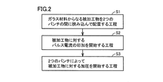
- the glass product manufacturing method includes a step S1 in which a workpiece 5 made of a glass material is sandwiched between two opposing punches 2a and 2b, and a pulse current is applied to the workpiece 5.
- a pulse current is applied to the workpiece 5.
- step S2 for starting the workpiece 5 and the step S3 for starting pressurization of the workpiece 5 by the two punches 2a and 2b and the workpiece 5 is heated in a state where the temperature of the workpiece 5 is increased by applying a pulse current.
- a glass product is obtained from the workpiece 5 by discharge plasma processing in which the pressure is deformed by pressurization.
- the current and pressure profile of the glass product manufacturing method in the present embodiment is as shown in FIG.
- a glass product having a desired shape can be obtained.
- the mold used for molding and the surface coating material of the mold are not easily damaged by heat load.
- the temperature of the workpiece is increased by applying a pulse current, so that the glass product manufacturing apparatus can be simplified.
- FIG. 5 shows a conceptual diagram in the chamber 1 of the glass product manufacturing apparatus used in the glass product manufacturing method based on the prior art.
- the two punches 2a and 2b and the die 3 on which the workpiece 5 made of a glass material is arranged are heated by a heating element 14 arranged around.
- the temperature is measured by the thermocouple 4 embedded in the punch 2b.
- the punches 2a and 2b and the die 3 reach the processing temperature based on the glass transition temperature Tg and the deformation temperature Ts of the glass material, the workpiece 5 made of the glass material is added by the downward displacement of the punch 2b. Press and mold.
- the processing conditions are determined based on the temperature measured by the thermocouple 4 provided on the punch 2b.
- FIG. 6 shows a conceptual diagram in the chamber 1 of the discharge plasma processing apparatus 101 which is a glass product manufacturing apparatus used in the glass product manufacturing method in the present embodiment.
- the present embodiment it is possible to simultaneously apply and apply a pulse current to the workpiece 5.
- the step S2 for starting application of a pulse current to the workpiece 5 and the step S3 for starting pressurization on the workpiece 5 are performed simultaneously.
- the waiting time for raising the temperature can be eliminated, and the processing time can be shortened.
- the application of the pulse current to the workpiece 5 by the pulse current application unit and the pressurization to the workpiece 5 by the punches 2a and 2b as holding units are performed simultaneously. It can be said that it is preferable.
- the processing conditions of the workpiece 5 are determined by the magnitude of the pulse current (current value) and the application time. Specifically, pressurization is started simultaneously with the application of the pulse current, and the applied pressure is released after the application of the pulse current is stopped. For this reason, in the manufacturing method of the glass product in this Embodiment, it does not depend on the physical-property value (glass transition temperature Tg, yielding temperature Ts, etc.) of glass material.
- a glass product such as a glass lens is manufactured at a maximum temperature reached when the workpiece 5 is processed is lower by 50 ° C. to 100 ° C. than the deformation temperature Ts of the glass material. Can do. For this reason, the mold used for molding and the surface coating material of the mold are not exposed to high temperatures, the mold and the surface coating material are not easily damaged by heat load, and the product life of the mold and the surface coating material is extended. . In addition, since it is not necessary to rapidly increase or decrease the temperature when processing the workpiece 5, the glass product manufacturing apparatus does not become complicated and large, and the cost of the glass product manufacturing apparatus decreases.
- discharge plasma processing apparatus 101 which is a glass product manufacturing apparatus used in the glass product manufacturing method in the present embodiment
- a heating element as provided in a glass product manufacturing apparatus used in a glass product manufacturing method based on the prior art. Is provided with a DC pulse power source 6 for applying a pulse current to the workpiece 5 as shown in FIG. For this reason, it is not necessary to install a heating element in the chamber 1 of the discharge plasma processing apparatus 101, and the glass product manufacturing apparatus can have a simple structure.
- the glass product manufacturing apparatus used in the glass product manufacturing method based on the prior art, a heat insulating structure for heat insulation including the heating element is required, but the glass used in the glass product manufacturing method in the present embodiment. Since the discharge plasma processing apparatus 101, which is a product manufacturing apparatus, only needs to have a heat insulating structure that insulates only the punches 2a and 2b and the die 3, the glass product manufacturing apparatus can be downsized.
- the discharge plasma processing apparatus 101 which is a glass product manufacturing apparatus used in the glass product manufacturing method in the present embodiment, it is for temperature control like the glass product manufacturing apparatus used in the glass product manufacturing method based on the prior art.
- the program controller for pulse current control is provided.
- thermocouple 4 provided on the die 3 and the punches 2a and 2b is used not for temperature control but for detecting trouble such as abnormal heat generation.
- Example 7 As a more specific embodiment of the present invention, an example is shown in which a glass lens is manufactured by processing a workpiece made of a glass material having a deformation temperature of 650 ° C. and having a diameter of 15 mm and a thickness of 3 mm.
- FIG. 7 is a graph showing a profile of current, temperature, displacement, and applied pressure in this example. The temperature is measured with a thermocouple.
- the initial state was assumed.
- the current value of the applied pulse current was increased to 500 A in the first minute, then decreased to 400 A in one minute, and held in that state for one minute thereafter.
- the applied pressure was gradually increased to 2 kN, but the workpiece continued to be deformed without being broken, and a glass lens having a desired shape could be manufactured.
- the maximum temperature reached by the thermocouple provided on the die was 575 ° C.
- mold No longer exposed to high temperatures for a long time. Therefore, the mold and the surface coating material are not easily damaged by the heat load, and as a result, the product life of the mold and the surface coating material is extended.
- a glass product such as a glass lens can be manufactured at a maximum temperature at which the workpiece is processed is 50 ° C. to 100 ° C. lower than the deformation temperature Ts of the glass material. For this reason, the mold used for molding and the surface coating material of the mold are not exposed to high temperatures, the mold and the surface coating material are not easily damaged by heat load, and the product life of the mold and the surface coating material is extended. . Further, it is not necessary to rapidly increase or decrease the temperature during processing of the workpiece, and the glass product manufacturing apparatus does not become complicated and large, and the cost of the glass product manufacturing apparatus is reduced.
- the present invention can be used in a glass product manufacturing method and a glass product manufacturing apparatus.
- thermocouple 1 chamber, 2a, 2b punch, 3 die, 4 thermocouple, 5 work piece, 6 DC pulse power supply, 7a, 7b wiring, 8a, 8b displacement part, 14 heating element, 101 discharge plasma processing apparatus.
Landscapes
- Chemical & Material Sciences (AREA)
- Engineering & Computer Science (AREA)
- Materials Engineering (AREA)
- Organic Chemistry (AREA)
- Manufacturing & Machinery (AREA)
- Plasma Technology (AREA)
Description
本発明は、ガラス製品の製造方法およびガラス製品製造装置に関するものである。ガラス製品の例としては、たとえばガラスレンズを挙げることができる。
特開2011-16671号公報(特許文献1)には、被加工物であるガラス板材のガラス転移温度Tg以上の温度で、ガラス板材に対してモールド(型)を押し付けることにより、ガラス板材をガラスレンズに成形する、熱インプリント方式によるガラスレンズの製造方法が開示されている。
特開2011-184257号公報(特許文献2)には、Bi2O3を含むガラス材料からなる被加工物を成形型の加工面形状に合わせて加工(プリフォーム)した後に、ガラス材料からなる被加工物をガラス材料のガラス転移温度Tg以上、屈伏温度Ts以下の温度でアニールし、ガラス材料からなる被加工物を成形型で加圧して加工する、ガラスレンズの製造方法が開示されている。
特許文献1,2に記載のガラスレンズの製造方法では、ガラス材料のガラス転移温度Tgと屈伏温度Tsを基準としてガラス材料からなる被加工物の加工を行っている。一般的には、プリフォーム時の加工温度は、ガラス材料のガラス転移温度Tg~屈伏温度Tsであり、加圧成形時の加工温度は屈伏温度Tsよりも30~50℃高い温度である。
ところで、国際公開WO2011/089971号(特許文献3)には、2つのパンチの間に被加工物を配置した状態で、2つのパンチの間にパルス電流を印加して被加工物の温度を高くすることにより、被加工物を加工する放電プラズマ加工法により、半導体結晶体をレンズ等の所望の形状に変形させることが開示されている。しかし、ガラス製品全般の製造については何ら記載されていない。
近年、ガラスレンズの小型化および薄型化を実現するために、ガラス材料のガラス転移温度Tgと屈伏温度Tsとが高くなってきている。このため、ガラス材料からなる被加工物の加工温度が高くなり、成形に用いられる型や型の表面コート材が高い温度にさらされるため、型や表面コート材が熱負荷によってダメージを受けやすくなり、型や表面コート材の製品寿命が短くなるという問題がある。表面コート材は、たとえばDLC(Diamond Like Carbon)からなり、被加工物が型から離れやすくなるように型の表面に設けられている。
また、ガラス材料からなる被加工物の加工温度が高くなる一方で、ガラスレンズの製造装置では製造時間を短縮するためには、従来よりも加工時の温度上昇および温度降下を急速に行なうことになり、その結果、製造装置が複雑化、大型化し、製造装置のコストが上がるという問題がある。
そこで、本発明は、所望の形状のガラス製品を得ることができ、成形に用いられる型やガラス製品の型の表面コート材が熱負荷によるダメージを受けにくく、ガラス製品製造装置を単純な構造にすることができるガラス製品の製造方法およびガラス製品製造装置を提供することを目的とする。
上記目的を達成するため、本発明に基づくガラス製品の製造方法は、ガラス材料からなる被加工物を互いに対向する2つのパンチの間に挟み込んで配置する工程と、上記被加工物に対するパルス電流の印加を開始する工程と、上記2つのパンチによって上記被加工物に対する加圧を開始する工程とを含み、上記パルス電流の印加によって上記被加工物の温度を高くした状態で上記被加工物を変形させる放電プラズマ加工により、上記被加工物からガラス製品を得る。
また、本発明に基づくガラス製品製造装置は、パルス電流によってガラス材料からなる被加工物の温度を高くした状態で上記被加工物を変形させる放電プラズマ加工により、上記被加工物からガラス製品を製造するための装置であって、上記被加工物に対してパルス電流を印加するためのパルス電流印加部と、上記被加工物を挟み込んで保持し、加圧するための保持部とを備える。
本発明によれば、所望の形状のガラス製品を得ることができ、成形に用いられる型や型の表面コート材が熱負荷によるダメージを受けにくい。また、昇温はパルス電流の印加によって行なわれるので、ガラス製品製造装置を単純な構造にすることができる。
発明者は、本発明を検討するに当たって、以下のような従来技術に基づくガラス製品の製造方法を比較対象とした。
従来技術に基づくガラス製品の製造方法では、ガラス材料からなる被加工物を配置した2つのパンチとダイ(スリーブ)は、周囲に配置された発熱体によって加熱され、ガラス材料のガラス転移温度Tgおよび屈伏温度Tsを基準とする加工温度に到達した段階で被加工物をパンチによって加圧して成形することで、ガラス製品が製造される。被加工物の加工条件は、パンチに設けられた熱電対で測定された温度を基準として決められている。熱電対は、パンチに埋設されたり、ダイに埋設されたり、発熱体の近傍に配置されたりする。
図1は、従来技術に基づくガラス製品の製造方法における温度および加圧力のプロファイルを示すグラフである。図1に示すように、従来技術に基づくガラス製品の製造方法では、発熱体による被加工物を配置した2つのパンチとダイの昇温中は被加工物を加圧せず、ガラス材料の屈伏温度Tsを30~50℃超えた時点でパンチによる被加工物の加圧を開始し、降温を開始してガラス転移温度Tg以下になった点で加圧力を開放し、被加工物の冷却を開始する。冷却方法としては、放冷の場合と空気やN2ガスを吹き付けて急冷する場合とがある。
(実施の形態)
図2~図4を参照して、本発明に基づく実施の形態1におけるガラス製品の製造方法およびガラス製品製造装置について説明する。本実施の形態におけるガラス製品の製造方法のフローチャートを図2に示す。本実施の形態におけるガラス製品の製造方法で用いられるガラス製品製造装置である放電プラズマ加工装置の概念図を図3に示す。
図2~図4を参照して、本発明に基づく実施の形態1におけるガラス製品の製造方法およびガラス製品製造装置について説明する。本実施の形態におけるガラス製品の製造方法のフローチャートを図2に示す。本実施の形態におけるガラス製品の製造方法で用いられるガラス製品製造装置である放電プラズマ加工装置の概念図を図3に示す。
図3に示すように、放電プラズマ加工装置101は、チャンバ1と、上下方向に互いに対向する2つのパンチ2a,2bと、パンチ2a,2bを取り囲む円筒形のダイ3と、熱電対4と、直流パルス電源6と、配線7a,7bと、変位部8a,8bとを備える。パンチ2a,2bは、それぞれ導電性を有する。パンチ2a,2bとダイ3とは、チャンバ1の内部に配置されている。ガラス材料からなる被加工物5は、ダイ3の内部で2つのパンチ2a,2bに挟まれるように配置される。熱電対4は、被加工物5の加工中の温度を測定するために、一方の端部がダイ3の内部に至るように配置されている。変位部8a,8bには、それぞれパンチ2a,2bが固定されており、変位部8a,8bは、パンチ2a,2bをそれぞれ上下方向に変位させる。直流パルス電源6は、配線7a,7bにより、パンチ2a,2bと電気的に接続されている。
放電プラズマ加工装置101は、変位部8a,8bによるパンチ2a,2bの少なくとも一方の変位によって被加工物5を加圧するとともに、直流パルス電源6からパンチ2a,2b間にパルス電流を印加することにより、被加工物5を加工してガラス製品を製造する。すなわち、放電プラズマ加工装置101は、パルス電流によってガラス材料からなる被加工物5の温度を高くした状態で被加工物5を変形させる放電プラズマ加工により、被加工物5からガラス製品を製造するための装置であって、被加工物5に対してパルス電流を印加するためのパルス電流印加部としての直流パルス電源6と、被加工物5を挟み込んで保持し、加圧するための保持部としてのパンチ2a,2bとを備える。
本実施の形態におけるガラス製品の製造方法は、ガラス材料からなる被加工物5を互いに対向する2つのパンチ2a,2bの間に挟み込んで配置する工程S1と、被加工物5に対するパルス電流の印加を開始する工程S2と、2つのパンチ2a,2bによって被加工物5に対する加圧を開始する工程S3とを含み、パルス電流の印加によって被加工物5の温度を高くした状態で被加工物5を加圧により変形させる放電プラズマ加工により、被加工物5からガラス製品を得る。
本実施の形態におけるガラス製品の製造方法の電流および加圧力のプロファイルは図4に示すようになる。
本実施の形態におけるガラス製品の製造方法では、所望の形状のガラス製品を得ることができる。この際、成形に用いられる型や型の表面コート材が熱負荷によるダメージを受けにくい。また、本実施の形態におけるガラス製品の製造方法であれば、被加工物の昇温はパルス電流の印加によって行なわれるので、ガラス製品製造装置を単純化することができる。
本実施の形態におけるガラス製品の製造方法においては、ガラス材料のガラス転移温度Tgおよび屈伏温度Tsを基準としてガラス材料からなる被加工物の加工を行なう必要がない。比較のために、従来技術に基づくガラス製品の製造方法で用いられるガラス製品製造装置のチャンバ1内の概念図を図5に示す。
従来技術に基づくガラス製品の製造方法では、ガラス材料からなる被加工物5を配置した2つのパンチ2a,2bおよびダイ3は、周囲に配置された発熱体14によって加熱される。このとき、パンチ2bに埋設された熱電対4によって温度が測定される。パンチ2a,2bおよびダイ3がガラス材料のガラス転移温度Tgおよび屈伏温度Tsを基準とする加工温度に到達した段階で、パンチ2bが下方に変位することによってガラス材料からなる被加工物5を加圧し、成形する。加工条件は、パンチ2bに設けられた熱電対4で測定された温度を基準として決められている。
これに対して、本実施の形態におけるガラス製品の製造方法で用いられるガラス製品製造装置である放電プラズマ加工装置101のチャンバ1内の概念図を図6に示す。本実施の形態では、被加工物5に対するパルス電流の印加と加圧とを同時に行なうことができる。
本実施の形態におけるガラス製品の製造方法では、被加工物5に対するパルス電流の印加を開始する工程S2と、被加工物5に対する加圧を開始する工程S3とが同時に行なわれることがより好ましい。この場合、昇温のための待ち時間をなくすことができ、加工時間を短縮することができる。
同様に、本実施の形態におけるガラス製品製造装置では、パルス電流印加部による被加工物5に対するパルス電流の印加と、保持部としてのパンチ2a,2bによる被加工物5に対する加圧とが同時に行なわれることが好ましいといえる。
本実施の形態におけるガラス製品の製造方法では、被加工物5の加工条件はパルス電流の大きさ(電流値)と印加時間とで定められる。具体的には、パルス電流の印加と同時に加圧を開始し、パルス電流の印加を止めた後に加圧力を開放する。このため、本実施の形態におけるガラス製品の製造方法では、ガラス材料の物性値(ガラス転移温度Tg、屈伏温度Tsなど)にとらわれない。
本実施の形態におけるガラス製品の製造方法では、被加工物5の加工時の最高到達温度がガラス材料の屈伏温度Tsから50℃~100℃低い温度で、ガラスレンズなどのガラス製品を製造することができる。このため、成形に用いられる型や型の表面コート材が高い温度にさらされることがなく、型や表面コート材が熱負荷によるダメージを受けにくくなり、型や表面コート材の製品寿命が長くなる。また、被加工物5の加工時の温度上昇・温度降下を急速に行なう必要がなくなるので、ガラス製品製造装置が複雑化・大型化せず、ガラス製品製造装置のコストが下がる。
本実施の形態におけるガラス製品の製造方法で用いられるガラス製品製造装置である放電プラズマ加工装置101では、従来技術に基づくガラス製品の製造方法で用いられるガラス製品製造装置に備わっていたような発熱体が不要である一方で、図3に示すような被加工物5にパルス電流を印加する直流パルス電源6を備える。このため、放電プラズマ加工装置101のチャンバ1内に発熱体を設置する必要がなくなり、ガラス製品製造装置を単純な構造にすることができる。
さらに、従来技術に基づくガラス製品の製造方法で用いられるガラス製品製造装置では、発熱体を含めて断熱する断熱構造が必要であったが、本実施の形態におけるガラス製品の製造方法で用いられるガラス製品製造装置である放電プラズマ加工装置101では、パンチ2a,2bおよびダイ3だけを断熱する断熱構造を備えていればよいため、ガラス製品製造装置を小型化することができる。
また、本実施の形態におけるガラス製品の製造方法で用いられるガラス製品製造装置である放電プラズマ加工装置101では、従来技術に基づくガラス製品の製造方法で用いられるガラス製品製造装置のような温度制御用のプログラム制御器が不要である一方で、パルス電流制御用のプログラム制御器を備える。
なお、ダイ3やパンチ2a,2bに設けられた熱電対4は、温度制御のためではなく、異常発熱などのトラブル検知用として用いられる。
(実施例)
本発明のより具体的な実施例として、屈伏温度が650℃であるガラス材料からなり、直径15mm、厚み3mmである被加工物を加工してガラスレンズを製造した例を示す。図7は、本実施例における電流、温度、変位量、加圧力のプロファイルを示すグラフである。温度は、熱電対で測定したものである。
本発明のより具体的な実施例として、屈伏温度が650℃であるガラス材料からなり、直径15mm、厚み3mmである被加工物を加工してガラスレンズを製造した例を示す。図7は、本実施例における電流、温度、変位量、加圧力のプロファイルを示すグラフである。温度は、熱電対で測定したものである。
屈伏温度が650℃であるガラス材料からなり、直径15mm、厚み3mmである被加工物を、2つのパンチの間に配置し、2つのパンチの間に0.1kNの加圧力をかけた状態を初期状態とした。図7に示すように、印加するパルス電流の電流値は最初の1分間で500Aまで上げ、その後1分間で400Aまで下げ、その状態でその後1分間保持した。この間、加圧力を2kNまで漸増させたが、被加工物は破壊されることなく変形を続け、所望の形状を有するガラスレンズを製造することができた。このとき、ダイに設けられた熱電対の最高到達温度は575℃であった。
ここでは、ガラスレンズを製造する例を示したが、ガラスレンズ以外のガラス製品の製造においても、本発明は同様に適用することができる。
このように、本発明に基づくガラス製品の製造方法によれば、ガラス材料の屈伏温度以下で被加工物を加圧して加工することができるとともに、成形に用いられる型や型の表面コート材が高い温度に長時間さらされることがなくなる。したがって、型や表面コート材が熱負荷によるダメージを受けにくくなり、その結果、型や表面コート材の製品寿命が長くなる。
本発明では、被加工物の加工時の最高到達温度がガラス材料の屈伏温度Tsから50℃~100℃低い温度でガラスレンズなどのガラス製品を製造することができる。このため、成形に用いられる型や型の表面コート材が高い温度にさらされることがなく、型や表面コート材が熱負荷によるダメージを受けにくくなり、型や表面コート材の製品寿命が長くなる。また、被加工物の加工時の温度上昇・温度降下を急速に行なう必要がなくなり、ガラス製品製造装置が複雑化・大型化せず、ガラス製品製造装置のコストが下がる。
なお、今回開示した上記実施の形態はすべての点で例示であって制限的なものではない。本発明の範囲は上記した説明ではなくて請求の範囲によって示され、請求の範囲と均等の意味および範囲内でのすべての変更を含むものである。
本発明は、ガラス製品の製造方法およびガラス製品製造装置に利用することができる。
1 チャンバ、2a,2b パンチ、3 ダイ、4 熱電対、5 被加工物、6 直流パルス電源、7a,7b 配線、8a,8b 変位部、14 発熱体、101 放電プラズマ加工装置。
Claims (4)
- ガラス材料からなる被加工物を互いに対向する2つのパンチの間に挟み込んで配置する工程と、
前記被加工物に対するパルス電流の印加を開始する工程と、
前記2つのパンチによって前記被加工物に対する加圧を開始する工程とを含み、
前記パルス電流の印加によって前記被加工物の温度を高くした状態で前記被加工物を変形させる放電プラズマ加工により、前記被加工物からガラス製品を得る、ガラス製品の製造方法。 - 前記被加工物に対するパルス電流の印加を開始する工程と、前記2つのパンチによって前記被加工物に対する加圧を開始する工程とが同時に行なわれる、請求項1に記載のガラス製品の製造方法。
- パルス電流によってガラス材料からなる被加工物の温度を高くした状態で前記被加工物を変形させる放電プラズマ加工により、前記被加工物からガラス製品を製造するための装置であって、
前記被加工物に対してパルス電流を印加するためのパルス電流印加部と、
前記被加工物を挟み込んで保持し、加圧するための保持部とを備える、ガラス製品製造装置。 - 前記パルス電流印加部による前記被加工物に対するパルス電流の印加と、前記保持部による前記被加工物に対する加圧とが同時に行なわれる、請求項3に記載のガラス製品製造装置。
Priority Applications (2)
| Application Number | Priority Date | Filing Date | Title |
|---|---|---|---|
| JP2014526836A JP5751386B2 (ja) | 2012-07-25 | 2013-07-02 | ガラス製品の製造方法およびガラス製品製造装置 |
| US14/597,287 US20150121963A1 (en) | 2012-07-25 | 2015-01-15 | Glass product manufacturing method and glass product manufacturing apparatus |
Applications Claiming Priority (2)
| Application Number | Priority Date | Filing Date | Title |
|---|---|---|---|
| JP2012-164468 | 2012-07-25 | ||
| JP2012164468 | 2012-07-25 |
Related Child Applications (1)
| Application Number | Title | Priority Date | Filing Date |
|---|---|---|---|
| US14/597,287 Continuation US20150121963A1 (en) | 2012-07-25 | 2015-01-15 | Glass product manufacturing method and glass product manufacturing apparatus |
Publications (1)
| Publication Number | Publication Date |
|---|---|
| WO2014017263A1 true WO2014017263A1 (ja) | 2014-01-30 |
Family
ID=49997079
Family Applications (1)
| Application Number | Title | Priority Date | Filing Date |
|---|---|---|---|
| PCT/JP2013/068132 Ceased WO2014017263A1 (ja) | 2012-07-25 | 2013-07-02 | ガラス製品の製造方法およびガラス製品製造装置 |
Country Status (3)
| Country | Link |
|---|---|
| US (1) | US20150121963A1 (ja) |
| JP (1) | JP5751386B2 (ja) |
| WO (1) | WO2014017263A1 (ja) |
Citations (4)
| Publication number | Priority date | Publication date | Assignee | Title |
|---|---|---|---|---|
| JPH1111961A (ja) * | 1997-06-19 | 1999-01-19 | Asahi Optical Co Ltd | 石英ガラスの製造方法 |
| JP2006327875A (ja) * | 2005-05-26 | 2006-12-07 | Olympus Corp | 光学素子用材料及び光学素子用材料の製造方法 |
| WO2011089971A1 (ja) * | 2010-01-20 | 2011-07-28 | 株式会社村田製作所 | 半導体結晶体の加工方法、および半導体結晶体の加工装置 |
| JP2011195424A (ja) * | 2010-03-24 | 2011-10-06 | Akita Seisakusho:Kk | 成形型 |
Family Cites Families (1)
| Publication number | Priority date | Publication date | Assignee | Title |
|---|---|---|---|---|
| US6222242B1 (en) * | 1998-07-27 | 2001-04-24 | Komatsu Ltd. | Thermoelectric semiconductor material and method of manufacturing same |
-
2013
- 2013-07-02 WO PCT/JP2013/068132 patent/WO2014017263A1/ja not_active Ceased
- 2013-07-02 JP JP2014526836A patent/JP5751386B2/ja not_active Expired - Fee Related
-
2015
- 2015-01-15 US US14/597,287 patent/US20150121963A1/en not_active Abandoned
Patent Citations (4)
| Publication number | Priority date | Publication date | Assignee | Title |
|---|---|---|---|---|
| JPH1111961A (ja) * | 1997-06-19 | 1999-01-19 | Asahi Optical Co Ltd | 石英ガラスの製造方法 |
| JP2006327875A (ja) * | 2005-05-26 | 2006-12-07 | Olympus Corp | 光学素子用材料及び光学素子用材料の製造方法 |
| WO2011089971A1 (ja) * | 2010-01-20 | 2011-07-28 | 株式会社村田製作所 | 半導体結晶体の加工方法、および半導体結晶体の加工装置 |
| JP2011195424A (ja) * | 2010-03-24 | 2011-10-06 | Akita Seisakusho:Kk | 成形型 |
Also Published As
| Publication number | Publication date |
|---|---|
| JP5751386B2 (ja) | 2015-07-22 |
| US20150121963A1 (en) | 2015-05-07 |
| JPWO2014017263A1 (ja) | 2016-07-07 |
Similar Documents
| Publication | Publication Date | Title |
|---|---|---|
| JP2011528995A5 (ja) | ||
| CN101845606A (zh) | 电流自阻加热成形铝基复合材料薄壁零件方法 | |
| US9815103B2 (en) | Warm working method for stainless steel foil and mold for warm working | |
| JP4679546B2 (ja) | プレス成形方法 | |
| JP5751386B2 (ja) | ガラス製品の製造方法およびガラス製品製造装置 | |
| JP2010207887A (ja) | 軽合金材料製プレス成形品のプレス成形用金型 | |
| TWI481570B (zh) | 連續式工件模造設備及方法 | |
| CN107282929A (zh) | 纤维定向增强复合材料电流直加热粉末热挤压制备方法及装置 | |
| JP6807161B2 (ja) | 成形装置及び成形方法 | |
| JP5224259B2 (ja) | マグネシウム合金薄板の塑性加工方法 | |
| JP2007260761A (ja) | 熱間プレス装置 | |
| CN107382040A (zh) | 一种高良率移动终端3d防护玻璃罩热压成型装置 | |
| JP2013026400A (ja) | 半導体結晶体の加工方法 | |
| JP2011513166A (ja) | 加熱成形によるガラス製品の製造装置及び製造方法 | |
| CN107365063A (zh) | 一种智能高良率移动终端3d防护玻璃罩热压成型装置 | |
| JP5981551B2 (ja) | 放電プラズマ加工装置および放電プラズマ加工品の製造方法 | |
| CN110125272A (zh) | 用于成形微型散热器微槽道薄板装置及方法 | |
| JP2004331471A (ja) | 光学素子の成形方法及び成形装置 | |
| WO2014041583A1 (ja) | 金属板の温間プレス成形方法 | |
| JP4035817B2 (ja) | 熱可塑性樹脂成形体の溶着方法及びその装置 | |
| JP2003096505A (ja) | ハイブリッドホットプレスとその制御方法 | |
| CN107382041A (zh) | 一种移动终端3d防护玻璃罩热压成型装置 | |
| JP6018469B2 (ja) | ステンレス鋼箔の温間加工方法 | |
| JP2003053829A (ja) | シート成形方法およびその成形装置 | |
| JP5399673B2 (ja) | 成形装置及び成形品の製造方法 |
Legal Events
| Date | Code | Title | Description |
|---|---|---|---|
| 121 | Ep: the epo has been informed by wipo that ep was designated in this application |
Ref document number: 13823316 Country of ref document: EP Kind code of ref document: A1 |
|
| ENP | Entry into the national phase |
Ref document number: 2014526836 Country of ref document: JP Kind code of ref document: A |
|
| NENP | Non-entry into the national phase |
Ref country code: DE |
|
| 122 | Ep: pct application non-entry in european phase |
Ref document number: 13823316 Country of ref document: EP Kind code of ref document: A1 |