WO2014017007A1 - 蓄冷熱交換器 - Google Patents
蓄冷熱交換器 Download PDFInfo
- Publication number
- WO2014017007A1 WO2014017007A1 PCT/JP2013/003663 JP2013003663W WO2014017007A1 WO 2014017007 A1 WO2014017007 A1 WO 2014017007A1 JP 2013003663 W JP2013003663 W JP 2013003663W WO 2014017007 A1 WO2014017007 A1 WO 2014017007A1
- Authority
- WO
- WIPO (PCT)
- Prior art keywords
- cold storage
- storage material
- container
- material container
- inner fin
- Prior art date
- Legal status (The legal status is an assumption and is not a legal conclusion. Google has not performed a legal analysis and makes no representation as to the accuracy of the status listed.)
- Ceased
Links
Images








Classifications
-
- F—MECHANICAL ENGINEERING; LIGHTING; HEATING; WEAPONS; BLASTING
- F28—HEAT EXCHANGE IN GENERAL
- F28D—HEAT-EXCHANGE APPARATUS, NOT PROVIDED FOR IN ANOTHER SUBCLASS, IN WHICH THE HEAT-EXCHANGE MEDIA DO NOT COME INTO DIRECT CONTACT
- F28D1/00—Heat-exchange apparatus having stationary conduit assemblies for one heat-exchange medium only, the media being in contact with different sides of the conduit wall, in which the other heat-exchange medium is a large body of fluid, e.g. domestic or motor car radiators
- F28D1/02—Heat-exchange apparatus having stationary conduit assemblies for one heat-exchange medium only, the media being in contact with different sides of the conduit wall, in which the other heat-exchange medium is a large body of fluid, e.g. domestic or motor car radiators with heat-exchange conduits immersed in the body of fluid
- F28D1/04—Heat-exchange apparatus having stationary conduit assemblies for one heat-exchange medium only, the media being in contact with different sides of the conduit wall, in which the other heat-exchange medium is a large body of fluid, e.g. domestic or motor car radiators with heat-exchange conduits immersed in the body of fluid with tubular conduits
- F28D1/053—Heat-exchange apparatus having stationary conduit assemblies for one heat-exchange medium only, the media being in contact with different sides of the conduit wall, in which the other heat-exchange medium is a large body of fluid, e.g. domestic or motor car radiators with heat-exchange conduits immersed in the body of fluid with tubular conduits the conduits being straight
- F28D1/0535—Heat-exchange apparatus having stationary conduit assemblies for one heat-exchange medium only, the media being in contact with different sides of the conduit wall, in which the other heat-exchange medium is a large body of fluid, e.g. domestic or motor car radiators with heat-exchange conduits immersed in the body of fluid with tubular conduits the conduits being straight the conduits having a non-circular cross-section
- F28D1/05366—Assemblies of conduits connected to common headers, e.g. core type radiators
- F28D1/05391—Assemblies of conduits connected to common headers, e.g. core type radiators with multiple rows of conduits or with multi-channel conduits combined with a particular flow pattern, e.g. multi-row multi-stage radiators
-
- F—MECHANICAL ENGINEERING; LIGHTING; HEATING; WEAPONS; BLASTING
- F25—REFRIGERATION OR COOLING; COMBINED HEATING AND REFRIGERATION SYSTEMS; HEAT PUMP SYSTEMS; MANUFACTURE OR STORAGE OF ICE; LIQUEFACTION SOLIDIFICATION OF GASES
- F25B—REFRIGERATION MACHINES, PLANTS OR SYSTEMS; COMBINED HEATING AND REFRIGERATION SYSTEMS; HEAT PUMP SYSTEMS
- F25B39/00—Evaporators; Condensers
- F25B39/02—Evaporators
- F25B39/022—Evaporators with plate-like or laminated elements
-
- F—MECHANICAL ENGINEERING; LIGHTING; HEATING; WEAPONS; BLASTING
- F28—HEAT EXCHANGE IN GENERAL
- F28D—HEAT-EXCHANGE APPARATUS, NOT PROVIDED FOR IN ANOTHER SUBCLASS, IN WHICH THE HEAT-EXCHANGE MEDIA DO NOT COME INTO DIRECT CONTACT
- F28D20/00—Heat storage plants or apparatus in general; Regenerative heat-exchange apparatus not covered by groups F28D17/00 or F28D19/00
- F28D20/02—Heat storage plants or apparatus in general; Regenerative heat-exchange apparatus not covered by groups F28D17/00 or F28D19/00 using latent heat
-
- F—MECHANICAL ENGINEERING; LIGHTING; HEATING; WEAPONS; BLASTING
- F28—HEAT EXCHANGE IN GENERAL
- F28F—DETAILS OF HEAT-EXCHANGE AND HEAT-TRANSFER APPARATUS, OF GENERAL APPLICATION
- F28F3/00—Plate-like or laminated elements; Assemblies of plate-like or laminated elements
- F28F3/02—Elements or assemblies thereof with means for increasing heat-transfer area, e.g. with fins, with recesses, with corrugations
- F28F3/025—Elements or assemblies thereof with means for increasing heat-transfer area, e.g. with fins, with recesses, with corrugations the means being corrugated, plate-like elements
- F28F3/027—Elements or assemblies thereof with means for increasing heat-transfer area, e.g. with fins, with recesses, with corrugations the means being corrugated, plate-like elements with openings, e.g. louvered corrugated fins; Assemblies of corrugated strips
-
- F—MECHANICAL ENGINEERING; LIGHTING; HEATING; WEAPONS; BLASTING
- F28—HEAT EXCHANGE IN GENERAL
- F28F—DETAILS OF HEAT-EXCHANGE AND HEAT-TRANSFER APPARATUS, OF GENERAL APPLICATION
- F28F3/00—Plate-like or laminated elements; Assemblies of plate-like or laminated elements
- F28F3/02—Elements or assemblies thereof with means for increasing heat-transfer area, e.g. with fins, with recesses, with corrugations
- F28F3/04—Elements or assemblies thereof with means for increasing heat-transfer area, e.g. with fins, with recesses, with corrugations the means being integral with the element
- F28F3/042—Elements or assemblies thereof with means for increasing heat-transfer area, e.g. with fins, with recesses, with corrugations the means being integral with the element in the form of local deformations of the element
- F28F3/046—Elements or assemblies thereof with means for increasing heat-transfer area, e.g. with fins, with recesses, with corrugations the means being integral with the element in the form of local deformations of the element the deformations being linear, e.g. corrugations
-
- F—MECHANICAL ENGINEERING; LIGHTING; HEATING; WEAPONS; BLASTING
- F25—REFRIGERATION OR COOLING; COMBINED HEATING AND REFRIGERATION SYSTEMS; HEAT PUMP SYSTEMS; MANUFACTURE OR STORAGE OF ICE; LIQUEFACTION SOLIDIFICATION OF GASES
- F25B—REFRIGERATION MACHINES, PLANTS OR SYSTEMS; COMBINED HEATING AND REFRIGERATION SYSTEMS; HEAT PUMP SYSTEMS
- F25B2400/00—Component parts or details not otherwise provided for in this subclass
- F25B2400/24—Thermal storage element
-
- F—MECHANICAL ENGINEERING; LIGHTING; HEATING; WEAPONS; BLASTING
- F28—HEAT EXCHANGE IN GENERAL
- F28D—HEAT-EXCHANGE APPARATUS, NOT PROVIDED FOR IN ANOTHER SUBCLASS, IN WHICH THE HEAT-EXCHANGE MEDIA DO NOT COME INTO DIRECT CONTACT
- F28D1/00—Heat-exchange apparatus having stationary conduit assemblies for one heat-exchange medium only, the media being in contact with different sides of the conduit wall, in which the other heat-exchange medium is a large body of fluid, e.g. domestic or motor car radiators
- F28D1/02—Heat-exchange apparatus having stationary conduit assemblies for one heat-exchange medium only, the media being in contact with different sides of the conduit wall, in which the other heat-exchange medium is a large body of fluid, e.g. domestic or motor car radiators with heat-exchange conduits immersed in the body of fluid
- F28D1/04—Heat-exchange apparatus having stationary conduit assemblies for one heat-exchange medium only, the media being in contact with different sides of the conduit wall, in which the other heat-exchange medium is a large body of fluid, e.g. domestic or motor car radiators with heat-exchange conduits immersed in the body of fluid with tubular conduits
- F28D1/0408—Multi-circuit heat exchangers, e.g. integrating different heat exchange sections in the same unit or heat exchangers for more than two fluids
- F28D1/0426—Multi-circuit heat exchangers, e.g. integrating different heat exchange sections in the same unit or heat exchangers for more than two fluids with units having particular arrangement relative to the large body of fluid, e.g. with interleaved units or with adjacent heat exchange units in common air flow or with units extending at an angle to each other or with units arranged around a central element
- F28D1/0435—Combination of units extending one behind the other
-
- F—MECHANICAL ENGINEERING; LIGHTING; HEATING; WEAPONS; BLASTING
- F28—HEAT EXCHANGE IN GENERAL
- F28D—HEAT-EXCHANGE APPARATUS, NOT PROVIDED FOR IN ANOTHER SUBCLASS, IN WHICH THE HEAT-EXCHANGE MEDIA DO NOT COME INTO DIRECT CONTACT
- F28D20/00—Heat storage plants or apparatus in general; Regenerative heat-exchange apparatus not covered by groups F28D17/00 or F28D19/00
- F28D2020/0004—Particular heat storage apparatus
- F28D2020/0008—Particular heat storage apparatus the heat storage material being enclosed in plate-like or laminated elements, e.g. in plates having internal compartments
-
- F—MECHANICAL ENGINEERING; LIGHTING; HEATING; WEAPONS; BLASTING
- F28—HEAT EXCHANGE IN GENERAL
- F28D—HEAT-EXCHANGE APPARATUS, NOT PROVIDED FOR IN ANOTHER SUBCLASS, IN WHICH THE HEAT-EXCHANGE MEDIA DO NOT COME INTO DIRECT CONTACT
- F28D20/00—Heat storage plants or apparatus in general; Regenerative heat-exchange apparatus not covered by groups F28D17/00 or F28D19/00
- F28D2020/0004—Particular heat storage apparatus
- F28D2020/0013—Particular heat storage apparatus the heat storage material being enclosed in elements attached to or integral with heat exchange conduits
-
- F—MECHANICAL ENGINEERING; LIGHTING; HEATING; WEAPONS; BLASTING
- F28—HEAT EXCHANGE IN GENERAL
- F28D—HEAT-EXCHANGE APPARATUS, NOT PROVIDED FOR IN ANOTHER SUBCLASS, IN WHICH THE HEAT-EXCHANGE MEDIA DO NOT COME INTO DIRECT CONTACT
- F28D21/00—Heat-exchange apparatus not covered by any of the groups F28D1/00 - F28D20/00
- F28D2021/0019—Other heat exchangers for particular applications; Heat exchange systems not otherwise provided for
- F28D2021/008—Other heat exchangers for particular applications; Heat exchange systems not otherwise provided for for vehicles
- F28D2021/0085—Evaporators
-
- F—MECHANICAL ENGINEERING; LIGHTING; HEATING; WEAPONS; BLASTING
- F28—HEAT EXCHANGE IN GENERAL
- F28F—DETAILS OF HEAT-EXCHANGE AND HEAT-TRANSFER APPARATUS, OF GENERAL APPLICATION
- F28F2275/00—Fastening; Joining
- F28F2275/12—Fastening; Joining by methods involving deformation of the elements
- F28F2275/122—Fastening; Joining by methods involving deformation of the elements by crimping, caulking or clinching
-
- Y—GENERAL TAGGING OF NEW TECHNOLOGICAL DEVELOPMENTS; GENERAL TAGGING OF CROSS-SECTIONAL TECHNOLOGIES SPANNING OVER SEVERAL SECTIONS OF THE IPC; TECHNICAL SUBJECTS COVERED BY FORMER USPC CROSS-REFERENCE ART COLLECTIONS [XRACs] AND DIGESTS
- Y02—TECHNOLOGIES OR APPLICATIONS FOR MITIGATION OR ADAPTATION AGAINST CLIMATE CHANGE
- Y02E—REDUCTION OF GREENHOUSE GAS [GHG] EMISSIONS, RELATED TO ENERGY GENERATION, TRANSMISSION OR DISTRIBUTION
- Y02E60/00—Enabling technologies; Technologies with a potential or indirect contribution to GHG emissions mitigation
- Y02E60/14—Thermal energy storage
Definitions
- the present disclosure relates to a cold storage heat exchanger used in a refrigeration cycle apparatus.
- a refrigeration cycle apparatus is used as an air conditioner. Attempts have been made to provide limited cooling even when the refrigeration cycle apparatus is stopped. For example, in a vehicle air conditioner, a compressor of a refrigeration cycle apparatus is driven by a traveling engine. For this reason, if the engine stops while the vehicle is temporarily stopped, the refrigeration cycle apparatus stops. In order to provide limited cooling during such a temporary stop, a cold storage heat exchanger in which a cold storage material for storing cold heat is added to the evaporator of the refrigeration cycle apparatus is disclosed (for example, Patent Document 1). reference).
- the cold storage heat exchanger described in Patent Document 1 includes an inner fin that increases the heat transfer area with the cold storage material inside the cold storage material container. Moreover, it has several uneven
- This indication aims at providing the cold storage heat exchanger which can improve the joining rate of a cold storage material container and an inner fin in view of the above-mentioned point.
- a cold storage heat exchanger includes a refrigerant passage and a plurality of refrigerant tubes that are stacked and spaced from each other;
- a regenerator container that divides a room for storing the material, a cooling air passage through which air that cools the space to be cooled flows when the regenerator material cools and cools from the regenerator material, and disposed inside the regenerator container
- an inner fin that increases the heat transfer area with the cold storage material.
- the inner fin has at least a plurality of flat portions perpendicular to the stacking direction of the refrigerant tubes, and all the flat portions of one inner fin are respectively in the flow direction of the air flowing through the cooling air passage. At least partially, it is joined to the inner surface of the cool storage material container.
- the regenerator heat exchanger has a refrigerant passage, a plurality of refrigerant tubes arranged in a stacked manner at intervals from each other, and joined to the refrigerant tube and accommodates the regenerator material.
- the cool storage material container that partitions the room, the cooling air passage through which the air that cools the cooling target space flows when storing the cool storage material and when leaving the cool storage material, and the cool storage material container and the cool storage Inner fins that increase the heat transfer area with the material.
- the cool storage material container has a pair of plate members, and a room for storing the cool storage material is formed between the pair of plate members.
- the inner fin has a plurality of flat portions perpendicular to the stacking direction of the refrigerant tubes and a connecting portion that connects adjacent flat portions, and the cross-sectional shape perpendicular to the longitudinal direction of the refrigerant tubes has a wave shape. Yes.
- the plurality of flat portions of the inner fin have end-side flat portions disposed at both end portions of the inner fin in the air flow direction that flows through the cooling air passage.
- the pair of plate members are joined to each other so as to have a room for accommodating the cold storage material between the pair of plate members with the end-side flat portion interposed therebetween.
- the pair of plate members among the plurality of flat portions of the inner fin, sandwiched between the end side flat portions disposed at both ends in the flow direction of the air flowing through the cooling air passage, A pair of plate members are joined so as to have a room for accommodating the regenerator material therebetween.
- the end side flat portions disposed at both ends in the air flow direction flowing through the cooling air passage may be brought into surface contact with a pair of plate members constituting the cold storage material container. it can.
- the brazing start point with the inner surface of the cool storage material container is secured at the end side plane portions arranged at both ends in the air flow direction through the cooling air passage among the plurality of plane portions of the inner fin. Therefore, it is possible to improve the joining rate between the cool storage material container and the inner fin.
- a plurality of refrigerant pipes that have refrigerant passages and are spaced apart from each other, a cold storage material container that is joined to the refrigerant pipes and that partitions a room for storing the cold storage material, and cold storage
- the cool storage material container has a pair of plate members joined so as to have a room for storing the cool storage material therebetween. At least one of the longitudinal end portion of the refrigerant pipe and the end portion of the air flow direction in the pair of plate members is a position shift that suppresses the position shift of the plate member when joining the pair of plate members.
- a suppression unit is provided.
- the regenerator heat exchanger includes a plurality of refrigerant tubes that have refrigerant passages and are arranged in a stacked manner at intervals, and a room that is joined to the refrigerant tubes and contains a regenerator material.
- the regenerator container to be partitioned, the cooling air passage through which the air that cools the cooling target space flows when the regenerator material cools and cools from the regenerator material, and the regenerator material is disposed inside the regenerator container and And an inner fin that increases the heat transfer area.
- the inner fin is formed in a wave shape and has a plurality of top portions. All the top portions of one inner fin are joined to the inner surface of the cool storage material container at least in a part in the flow direction of the air flowing through the cooling air passage.
- FIG. 10 is a sectional view taken along line XX in FIG. 9.
- FIG. 12B is a sectional view taken along line XIIB-XIIB in FIG. 12A. It is a perspective view showing an inner fin in a 6th embodiment of this indication. It is a partially exploded perspective view which shows the cool storage material container 47 in 7th Embodiment of this indication. It is a partially exploded perspective view which shows the cool storage material container 47 in the modification of 7th Embodiment. It is a partial side view which shows the inner fin in other embodiment of this indication. It is a side view showing an inner fin in other embodiments of this indication.
- FIG. 1 shows a configuration of a refrigeration cycle apparatus that constitutes the vehicle air conditioner according to the first embodiment of the present disclosure.
- the refrigeration cycle apparatus 1 constituting the air conditioner includes a compressor 10, a radiator 20, a decompressor 30, and an evaporator (evaporator) 40. These components are connected in an annular shape by piping and constitute a refrigerant circulation path.
- the compressor 10 is driven by an internal combustion engine (or an electric motor or the like) that is a power source 2 for traveling the vehicle. When the power source 2 stops, the compressor 10 also stops.
- the compressor 10 sucks the refrigerant from the evaporator 40, compresses it, and discharges it to the radiator 20.
- the radiator 20 cools the high-temperature refrigerant.
- the radiator 20 is also called a condenser.
- the decompressor 30 decompresses the refrigerant cooled by the radiator 20.
- the evaporator 40 evaporates the refrigerant decompressed by the decompressor 30 and cools the passenger compartment air.
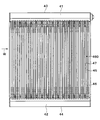
- the evaporator 40 has a first heat exchange section 48 and a second heat exchange section 49 arranged in two layers. And the 2nd heat exchange part 49 is arrange
- the evaporator 40 has a refrigerant passage member branched into a plurality.
- the refrigerant passage member is provided by a metal passage member such as aluminum.
- the refrigerant passage member is provided by first to fourth headers 41 to 44 positioned in a set, and a plurality of tubes 45 connecting the headers 41 to 44.
- the first header 41 and the second header 42 form a pair, and are arranged in parallel at a predetermined distance from each other.
- the third header 43 and the fourth header 44 also form a pair, and are arranged in parallel at a predetermined distance from each other.
- a plurality of tubes 45 are arranged at equal intervals between the first header 41 and the second header 42. Each tube 45 communicates with the corresponding header 41, 42 at its end.
- a first heat exchanging portion 48 (see FIG. 3) is formed by the first header 41, the second header 42, and a plurality of tubes 45 arranged therebetween.
- a plurality of tubes 45 are arranged at equal intervals between the third header 43 and the fourth header 44. Each tube 45 communicates with the corresponding header 43, 44 at its end.
- a second heat exchanging portion 49 (see FIG. 3) is formed by the third header 43, the fourth header 44, and a plurality of tubes 45 arranged therebetween.
- a joint (not shown) as a refrigerant inlet is provided at the end of the first header 41.
- the inside of the first header 41 is partitioned into a first partition and a second partition by a partition plate (not shown) provided substantially at the center in the length direction.
- the plurality of tubes 45 are divided into a first group and a second group.
- the refrigerant is supplied to the first section of the first header 41.
- the refrigerant is distributed from the first section to the plurality of tubes 45 belonging to the first group.
- the refrigerant flows into the second header 42 through the first group and is collected.
- the refrigerant is distributed again from the second header 42 to the plurality of tubes 45 belonging to the second group.
- the refrigerant flows into the second section of the first header 41 through the second group.
- a joint (not shown) as a refrigerant outlet is provided.
- the inside of the third header 43 is partitioned into a first partition and a second partition by a partition plate (not shown) provided substantially at the center in the length direction.
- the plurality of tubes 45 are divided into a first group and a second group.
- the first section of the third header 43 is adjacent to the second section of the first header 41.
- the first section of the third header 43 and the second section of the first header 41 are in communication.
- the refrigerant flows from the second section of the first header 41 into the first section of the third header 43.
- the refrigerant is distributed from the first section to the plurality of tubes 45 belonging to the first group.
- the refrigerant flows into the fourth header 44 through the first group and is collected.
- the refrigerant is distributed again from the fourth header 44 to the plurality of tubes 45 belonging to the second group.
- the refrigerant flows into the second section of the third header 43 through the second group.
- coolant in a U shape is formed.
- the refrigerant in the second section of the third header 43 flows out from the refrigerant outlet and flows toward the compressor 10.
- the plurality of tubes 45 are arranged at substantially constant intervals.
- a plurality of gaps are formed between the plurality of tubes 45.
- a plurality of air-side fins 46 and a plurality of cold storage material containers 47 are brazed to the plurality of gaps.
- the plurality of air-side fins 46 and the plurality of cold storage material containers 47 are arranged with a predetermined regularity, for example.
- a part of the gap is a cooling air passage 460.
- the remaining part of the gap is an accommodating part in which the cool storage material container 47 is arranged.
- the cool storage material containers 47 are arranged almost uniformly distributed throughout the evaporator 40.
- the two tubes 45 located on both sides of the cold storage material container 47 define a cooling air passage 460 for exchanging heat with air on the opposite side to the cold storage material container 47.
- the tube 45 is a multi-hole tube formed in a flat shape and having a plurality of refrigerant passages therein.
- the tube 45 can be obtained by, for example, an extrusion method.
- the plurality of refrigerant passages extend along the longitudinal direction of the tube 45 and open at both ends of the tube 45.
- the plurality of tubes 45 are arranged in a row. In each row, the plurality of tubes 45 are arranged such that their main surfaces (flat surfaces) face each other.
- the evaporator 40 includes air-side fins 46 in the cooling air passage 460 for increasing the contact area with the air supplied to the passenger compartment.
- the air-side fins 46 are disposed in an air passage that is defined between two adjacent tubes 45.
- the air side fin 46 is thermally coupled to the two adjacent tubes 45.
- the air-side fins 46 are joined to two adjacent tubes 45 by a brazing material.
- the air-side fin 46 is formed by bending a thin metal plate such as aluminum into a corrugated shape, and includes an armor window-shaped louver 461 (see FIG. 4).
- the evaporator 40 When the evaporator 40 evaporates the refrigerant in the evaporator 40 and exhibits an endothermic effect, the evaporator 40 solidifies the regenerator material to store the cold energy, and cools the stored heat when the regenerator material melts. It is an exchanger.
- the evaporator 40 has a cool storage material container 47 that partitions a room for storing a plurality of cool storage materials.
- the regenerator container 47 is made of metal such as aluminum and is formed in a flat container shape.
- the cold storage material container 47 has a pair of plate members 470 having a substantially U-shaped cross section (bathtub shape), and houses the cold storage material inside by joining the opening sides of the pair of plate members 470 to each other. The room is divided.
- the cold storage material container 47 has a wide main surface (flat surface) on both sides.
- the two main walls that provide these two main surfaces are each arranged in parallel with the tube 45. These two main walls have an uneven shape.
- a plurality of container side convex portions 47 a that protrude toward the outside of the cool storage material container 47 and a plurality of containers that are recessed inside the cool storage material container 47.
- a side recess 47b is provided.
- the cold storage material container 47 is disposed between two adjacent tubes 45.
- the cool storage material container 47 is thermally coupled to two tubes 45 disposed on both sides thereof by a container-side convex portion 47a.
- the cool storage material container 47 is joined to the two adjacent tubes 45 by a joining material excellent in heat transfer.
- a resin material such as a brazing material or an adhesive can be used.
- the cold storage material container 47 of this example is brazed to the tube 45. More specifically, both the tube 45 constituting the first heat exchange unit 48 and the tube 45 constituting the second heat exchange unit 49 are joined to the outer surface of the cold storage material container 47.
- a brazing material is disposed between the cold storage material container 47 and the tube 45 in order to connect them with a wide cross-sectional area.
- This brazing material can also be provided by placing a brazing material foil between the cold storage material container 47 and the tube 45. As a result, the cool storage material container 47 performs good heat conduction with the tube 45.
- the container side convex portion 47 a of the main wall of the cold storage material container 47 is brazed to the tube 45.
- Si silicon
- the ease of flowing into the brazing portion can be adjusted.
- the greater the amount of Si in the brazing material the easier it will flow into the brazing part.
- the container-side recess 47b in the main wall of the cool storage material container 47 constitutes a cool storage material-side air passage 462 through which air flows.
- the inner fin 60 is disposed on the inner side of the cool storage material container 47 so as to be thermally and mechanically coupled to the cool storage material container 47.
- the inner fin 60 is joined to the inner surface of the main wall of the cool storage material container 47 by a joining material excellent in heat transfer. This joining is made by brazing. Since the inner fin 60 is coupled to the inner side of the cold storage material container 47, deformation of the cold storage material container 47 is prevented and pressure resistance is improved.
- the inner fin 60 has a plurality of plane portions 61 perpendicular to the stacking direction of the tubes 45 and a connection portion 62 that positions the adjacent plane portions 61 at a predetermined distance.
- a cross-sectional shape orthogonal to the flow direction of air flowing through the cooling air passage 460 (perpendicular to the plane of FIG. 5) has a wave shape.
- the inner fin 60 is formed by bending a thin metal plate such as aluminum into a wave shape.
- the inner fin 60 does not need to have a plurality of flat portions 61 perpendicular to the stacking direction of the tubes 45, and may have a crest (top) instead. These peaks are connected to adjacent peaks by a connecting portion 62.
- the inner fin 60 is joined with the inner surface of the cool storage material container 47 located in the container inner side rather than the container side convex part 47a. More specifically, the inner fin 60 is joined to the container side concave portion 47b of the main wall of the cold storage material container 47, that is, a portion projecting inward (inner surface projection) by brazing, so that the mechanical strength and the pressure resistance performance are improved. It is increasing. Thereby, the container side convex part 47a and the inner fin 60 which protruded outside among the main walls of the cool storage material container 47 are not joined.
- All the flat portions 61 constituting one inner fin 60 are joined to the inner surface of the regenerator container 47 in at least a part in the flow direction of the air flowing through the cooling air passage 460.
- the container-side recess 47b of the main wall of the regenerator container 47 extends in the flow direction of the air flowing through the cooling air passage 460 (the left-right direction on the paper surface).
- the container-side concave portion 47b and the flat surface portion 61 of the inner fin 60 are in surface contact.
- one container-side convex portion 47a and one container-side concave portion 47b are provided at a portion of the cold storage material container 47 facing one tube 45. And in the site
- the clearance dimension of the brazing start point between the inner surface of the cool storage material container 47 and the surface of the inner fin 60 is changed, and the cool storage material container 47 at that time is changed.
- the brazing state between the inner surface of the inner fin and the surface of the inner fin 60 was determined.
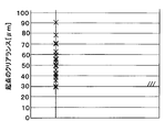
- the plot in FIG. 6 has shown the clearance dimension of the brazing start point in case brazing has generate
- all the flat portions 61 of one inner fin 60 are joined to the inner surface of the regenerator container 47 at least in part in the air flow direction through the cooling air passage 460.
- the brazing start point with the inner surface of the cold storage material container 47 can be ensured in all the flat portions 61 of one inner fin 60. Therefore, it is possible to improve the joining rate between the cold storage material container 47 and the inner fin 60.
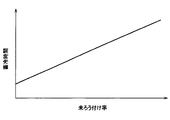
- FIG. 7 shows the relationship between the unbrazed rate of the cold storage material container 47 and the inner fin 60 and the cold storage time of the cold storage material during cold storage.
- the unbrazed rate is a brazed area when the inner surface of the cold storage material container 47 and the surface of the flat portion 61 of the inner fin 60 are completely brazed (hereinafter referred to as 100% brazed area).
- the lower the brazing rate between the cool storage material container 47 and the inner fin 60 the shorter the time required for storing the cool storage material.
- the cool storage time of a cool storage material becomes short by improving the joining rate of the cool storage material container 47 and the inner fin 60, and a cool storage material can be solidified in a short time. Therefore, it is possible to reliably cool the cold stored in the cold storage material during a temporary stop such as idling stop.
- the cold storage material container 47 or the inner fin 60 in order to solidify the cold storage material in a short time, it is effective to shorten the distance (phase change distance) from the cold storage material container 47 or the inner fin 60 to the cold storage material to be solidified. And by joining the inner fin 60 to the inner surface of the cool storage material container 47, the two phase change distances of the distance from the cool storage material container 47 to the cool storage material and the distance from the inner fin 60 to the cool storage material are shortened. There is a need to. By improving the brazing rate between the cold storage material container 47 and the inner fin 60, the effect of shortening the phase change distance by the inner fin 60 can be reliably exhibited.
- the concave and convex shapes of the inner fin and the cold storage material container are staggered, it may be difficult to secure the brazing start point (the part where the clearance between the inner surface of the cold storage material container and the inner fin is 30 ⁇ m or less). is there. For this reason, the cool storage material is pinched
- the amount of heat conduction is determined by the thermal conductivity and surface area of the substance, so if a heat storage material with low heat conductivity is sandwiched between the cold storage material container and the inner fin, the cold storage material container will move to the inner fin. The heat transfer is hindered and cold heat cannot be stored in the inner fin. For this reason, the effect which shortens the phase change distance by an inner fin cannot fully be acquired, and a cool storage material cannot be solidified in a short time.
- the effect of shortening the phase change distance by the inner fin 60 can be exhibited reliably by improving the joining rate of the cool storage material container 47 and the inner fin 60.
- the regenerator material can be solidified in a short time, even when the vehicle is operated for a short period of time, the cold heat stored in the regenerator material is allowed to cool sufficiently when the vehicle is temporarily stopped. It is possible to secure a time for releasing the cool air.
- the container-side convex portion 47a of the cold storage material container 47 is formed in an inverted V shape in which the central portion in the left-right direction (air flow direction) is arranged vertically above both ends. Yes.
- the plurality of inverted V-shaped container-side convex portions 47a are arranged side by side along the longitudinal direction of the cold storage material container 47, that is, the vertical direction.
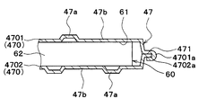
- a joining portion 471 is provided on the outer peripheral portion of the pair of plate members 470 of the cold storage material container 47, and the joining portions 471 are joined together, so that the plate members 4701 and 4702 are joined together.
- the joint portion 471 of one plate member 4701 has a plurality of claw portions 4701a, and the joint portion 471 of the other plate member 4702 has a plurality of notches 4702a.
- the plurality of claw portions 4701a are fitted in the plurality of notches 4702a and bent, whereby the one plate member 4701 and the other plate member 4702 are fixed by caulking.
- the plate member fixing method using the claw portion 4701a and the notch 4702a is also applicable to the first embodiment and the following embodiments.
- the planar portion 71 of the inner fin 70 is formed in a shape corresponding to the container-side convex portion 47 a of the cold storage material container 47. That is, the flat surface portion 71 of the inner fin 70 is formed in an inverted V shape in which the center portion in the left-right direction (air flow direction) is disposed on the upper side in the vertical direction from both ends. A plurality of inverted V-shaped flat portions 71 are arranged side by side along the longitudinal direction of the cool storage material container 47, that is, the vertical direction.
- the connecting portion 72 of the inner fin 70 that positions the adjacent flat portions 71 at a predetermined distance apart has a cross-sectional shape perpendicular to the stacking direction of the tubes 45 (the direction perpendicular to the paper surface), and the center portion in the left-right direction (the air flow direction) Is an inverted V-shape arranged vertically above the both ends.
- the inclination angle of the container-side convex portion of the cold storage material container 47 with respect to the horizontal direction is equal to the inclination angle of the flat portion 71 of the inner fin 70 with respect to the horizontal direction.
- the vertical length of the container-side convex portion 47 a of the cold storage material container 47 is equal to the vertical length of the flat surface portion 71 of the inner fin 70.
- the pitch (interval) of the plurality of container-side convex portions 47 a of the cold storage material container 47 is equal to the pitch (interval) of the plurality of flat surface portions 71 of the inner fin 70.
- the inner surface of the container-side convex portion 47 a of the plate members 4701 and 4702 of the cold storage material container 47 and the flat surface portion 71 of the inner fin 70 are in surface contact.
- the part 47a is arranged with a half-pitch shift. That is, the container-side convex portion 47 a of one plate member 4701 is opposed to the container-side concave portion 47 b of the other plate member 4702, and the container-side concave portion 47 b of one plate member 4701 is opposite to the other plate member 4702. It faces the container-side convex portion 47a.
- the planar portion 71 of the inner fin 70 is formed in a shape corresponding to the container-side convex portion 47a of the cold storage material container 47, and the inner surface of the container-side convex portion 47a of the cold storage material container 47 is formed on the inner surface.
- the container side convex part of the cool storage material container is formed in the inverted V shape
- vertical to an air flow direction is a wave shape
- the inner fin is the container side adjacent to a cool storage material container.
- the flow of the brazing material for joining the inner fin and the cold storage material container is divided by the container-side recess formed between the protrusions.
- the container side recessed part 47b is formed by forming the plane part 71 of the inner fin 70 in the shape (inverted V shape) corresponding to the container side convex part 47a of the cool storage material container 47 like this embodiment.
- the brazing material can be poured without being obstructed. Thereby, it becomes possible to braze the cool storage material container 47 and the inner fin 70 more reliably.
- the claw portion 4701a of one plate member 4701 is fitted into the notch 4702a of the other plate member 4702 and bent. Thereby, the amount by which the bent part of the claw part 4701a protrudes outside the joint part 471 can be reduced. Therefore, when assembled in the air conditioning unit, interference with other members arranged close to the evaporator 40 can be suppressed.
- a third embodiment of the present disclosure will be described based on FIGS. 9 and 10. Compared to the second embodiment, the third embodiment is different in the uneven shape of the inner surface of the cold storage material container 47, and uses the same inner fin as the inner fin 60 of the first embodiment. .
- the container-side convex portion 47a of the cold storage material container 47 is formed in an inverted V shape in which the center portion in the air flow direction (left and right direction on the paper surface) is arranged vertically above both ends. ing.
- the plurality of inverted V-shaped container-side convex portions 47a are arranged side by side along the longitudinal direction of the cold storage material container 47, that is, the vertical direction.
- the distance in the air flow direction from the center in the air flow direction to the end of the container-side convex portion 47a is referred to as a rib length L.
- the rib length L of some container-side protrusions 47a is the rib length of the other container-side protrusions 47a. It is shorter than L.
- the container side recessed part 47b is formed in the joint part 471 vicinity which joins the plate members 4701 and 4702 among the inner surfaces of the cool storage material container 47. As shown in FIG. And the inner surface of this container side recessed part 47b and the plane part 61 of the inner fin 60 surface-contact, and become a brazing start point.
- the container-side protrusion 47a having a long rib length L is referred to as a first container-side protrusion 471a.
- the container-side convex portion 47a having a rib length L shorter than the first container-side convex portion 471a is referred to as a second container-side convex portion 472a.
- the number of second container side convex portions 472a is smaller than the number of first container side convex portions 471a.
- the distance in the vertical direction between the central portions of the adjacent container side convex portions 47a in the air flow direction is referred to as a rib pitch p.
- the second container side convex portion 472a on the plate members 4701 and 4702 of the cold storage material container 47, the length in the vertical direction in the container side concave portion 47b formed in the vicinity of the joint portion 471 is referred to as a plane length l.
- the plane length l is longer than the rib pitch p.
- the cold storage material container 47 has an outer convex shape that protrudes outward when viewed as a whole, and in order to seal the inner fin 60 by crimping both ends of the pair of plate members 4701 and 4702 in the air flow direction, The clearance with the inner fin 60 tends to increase at the center of the cold storage material container 47.
- the rigidity of the cold storage material container 47 is high and the dimensional change is small.
- the cold storage container 47 is provided by providing the container-side recess 47b in the vicinity of the joint 471 on the inner surface of the cold storage container 47 as a starting point of brazing with the inner fin 60 as in the present embodiment. And the inner fin 60 can be securely brazed.
- a fourth embodiment of the present disclosure will be described based on FIG. The fourth embodiment is different from the third embodiment in the uneven shape of the inner surface of the cold storage material container 47.
- this part container side convex part 47a is called 3rd container side convex part 473a.
- the other container-side convex portion 47a has a rib length L on one side in the air flow direction (the right side in the drawing).
- the rib length is longer than the rib length L on the other side (left side of the paper) in the air flow direction.
- this other container side convex part 47a is called the 4th container side convex part 474a.
- the third container side convex portions 473a and the fourth container side convex portions 474a are alternately arranged along the vertical direction.
- a container-side recess 47b is formed in the vicinity of 471, that is, in a portion where the rigidity of the cold storage material container 47 is high. For this reason, according to the present embodiment, it is possible to obtain the same effects as those of the third embodiment. (Fifth embodiment) Next, a fifth embodiment of the present disclosure will be described based on FIGS. 12A and 12B. The fifth embodiment is different from the first embodiment in the shape of the inner fin.
- the container-side convex portion 47a of the cold storage material container 47 is formed in an inverted V-shape in which the center portion in the air flow direction (the left-right direction on the paper surface) is arranged vertically above both ends. ing.
- the plurality of inverted V-shaped container-side convex portions 47a are arranged side by side along the longitudinal direction of the cold storage material container 47, that is, the vertical direction.
- the inner fin 80 includes a plurality of plane portions 81 perpendicular to the stacking direction of the tubes 45 and a connection portion 82 that positions the adjacent plane portions 81 at a predetermined distance.
- the flat portion 81 extends in the longitudinal direction of the tube 45, and the inner fin 80 has a corrugated cross-sectional shape perpendicular to the longitudinal direction of the tube 45.
- planar portions hereinafter referred to as end-side planar portions 810) disposed at both ends in the air flow direction are sandwiched between a pair of plate members 4701 and 4702. Yes.
- the end side flat surface portion 810 of the inner fin 80 is sandwiched between the joint portions 471 that join the pair of plate members 4701 and 4702 together.
- the cold storage material container 47 joins the pair of plate members 4701 and 4702 so as to have a space therebetween, with the end-side flat portion 810 of the inner fin 80 sandwiched between the pair of plate members 470.
- the plurality of flat portions 81 may not be perpendicular to the stacking direction of the tubes 45 except for the end-side flat portion 810, and may be a peak portion (top portion) instead.
- the mountain portion is connected to the adjacent mountain portion by a connecting portion 82.
- the pair of plate members 470 are joined to each other with a space between the pair of plate members 470 with the end-side flat portion 810 of the inner fin 80 sandwiched therebetween. Therefore, the end side flat portion 810 of the inner fin 80 can be brought into surface contact with the pair of plate members 470 constituting the cold storage material container 47. For this reason, since the brazing start point with the inner surface of the cool storage material container 47 can be secured in the end side plane portion 810 of the inner fin 80, the joining rate between the cool storage material container 47 and the inner fin 80 is improved. Is possible. (Sixth embodiment) Next, a sixth embodiment of the present disclosure will be described based on FIG. The sixth embodiment differs from the first embodiment in the shape of the inner fin 60.
- the inner fin 60 of the present embodiment has a cross-sectional shape perpendicular to the flow direction of the air flowing through the cooling air passage 460 (see FIG. 5), with the planar portion 61 on one side and the other side.
- the corrugated portion is an offset fin that is offset with respect to the adjacent corrugated portion in the air flow direction.
- the cold storage material can be solidified in a short time.
- a seventh embodiment of the present disclosure will be described based on FIGS. 14A and 14B.
- the seventh embodiment differs from the second embodiment in the shape of a pair of plate members 470 that form the cold storage material container 47.
- a pair of plate members 4701, 4702 has a pair of plate members 4701, 4702 at the ends of the tubes 45 in the longitudinal direction (longitudinal direction of the regenerator container 47) and the air flow direction.
- a claw portion 475 is provided as a positional deviation suppressing portion for suppressing the positional deviation of the plate members 4701 and 4702 when they are joined to each other.
- the claw portion 475 can prevent the plate members 4701 and 4702 from being displaced in the longitudinal direction and the air flow direction of the tube 45 when the pair of plate members 4701 and 4702 are joined together. For this reason, when joining a pair of plate members 4701 and 4702, it can suppress that the positional relationship and dimensional relationship of the uneven
- a plurality of claw portions 4701a may be provided on the claw portion 475 as in the second embodiment.
- the present disclosure is not limited to the above-described embodiment, and can be variously modified as follows without departing from the spirit of the present disclosure.
- the present invention is not limited to this and may be arranged at the same pitch.
- the plane part 81 is extended in the longitudinal direction of the tube 45 inside the cool storage material container 47, and the cross-sectional shape orthogonal to the longitudinal direction of the tube 45 is wave shape 1
- the structure of the inner fin 80 is not limited to this.
- the planar portion 81 extends in the longitudinal direction of the tube 45, and a plurality of inner fins 80 whose cross-sectional shape orthogonal to the longitudinal direction of the tube 45 has a wave shape are connected to the tube 45. A plurality of them may be arranged along the longitudinal direction.
- the inner fin 60 may be formed in a fiber shape (fiber shape).
- the same shape as the inner fin 60 of the sixth embodiment may be applied to the inner fins 70, 80, 90.
- the claw portions 475 as the positional deviation suppressing portions are provided on both the longitudinal end portion of the tube 45 and the air flow direction end portion of the pair of plate members 470 .
- the present invention is not limited to this, and the claw portion 475 may be provided on either one of the end portion in the longitudinal direction of the tube 45 and the end portion in the air flow direction of the pair of plate members 470.
- a pair of plate members 470 (4701, 4702) are joined so as to have a space therebetween, thereby partitioning a room for storing the regenerator material.
- a room for storing the regenerator material may be defined by bending a single plate and opposingly joining the main surfaces.
- the inner fins 60, 70, 80, 90 have a plurality of plane portions 61, 71, 81, 91 perpendicular to the stacking direction of the tubes 45, but the plane portions 61, 71, 91, 81 and 91 may be peaks (tops) having curved surfaces.
Landscapes
- Engineering & Computer Science (AREA)
- Physics & Mathematics (AREA)
- Thermal Sciences (AREA)
- Mechanical Engineering (AREA)
- General Engineering & Computer Science (AREA)
- Heat-Exchange Devices With Radiators And Conduit Assemblies (AREA)
- Air-Conditioning For Vehicles (AREA)
Abstract
蓄冷熱交換器は、冷媒通路を有して互いに間隔を設けて配置された複数のチューブ(45)と、チューブに接合されて蓄冷材を収容する部屋を区画する蓄冷材容器(47)と、蓄冷材への蓄冷時および蓄冷材からの放冷時に冷却対象空間を冷却する空気が流通する冷却用空気通路(460)と、蓄冷材容器の内部に配置されて蓄冷材との伝熱面積を増大させるインナーフィン(60、70、80、90)とを備える。インナーフィンは、チューブ積層方向に対して垂直な複数の平面部(61、71、81、91)を少なくとも有しており、1つのインナーフィンの全ての平面部は、それぞれ、冷却用空気通路を流通する空気の流れ方向における少なくとも一部において、蓄冷材容器の内側表面に接合されている。これにより、蓄冷材容器とインナーフィンとの接合率を向上させることができる。
Description
本出願は、当該開示内容が参照によって本出願に組み込まれた、2012年7月23日に出願された日本特許出願2012-162825を基にしている。
本開示は、冷凍サイクル装置に用いられる蓄冷熱交換器に関するものである。
従来、空調装置には、冷凍サイクル装置が用いられている。この冷凍サイクル装置が停止している状態においても、限定された冷房を提供する試みがなされている。例えば、車両用空調装置では、走行用エンジンによって冷凍サイクル装置の圧縮機が駆動される。このため、車両が一時的に停車している間にエンジンが停止すると、冷凍サイクル装置が停止する。このような一時的な停車中に、限定された冷房を提供するために、冷凍サイクル装置の蒸発器に冷熱を蓄える蓄冷材を付加した蓄冷熱交換器が開示されている(例えば、特許文献1参照)。
この特許文献1に記載の蓄冷熱交換器では、蓄冷材容器の内部に、蓄冷材との伝熱面積を増大させるインナーフィンを備えている。また、蓄冷材容器の外側表面および内側表面に、複数の凹凸形状を有している。
しかしながら、本願の発明者の検討によると、開示上記特許文献1に記載の蓄冷熱交換器では、蓄冷材容器の内側表面に設けられた凸部(蓄冷材容器の外側に向かって突出する部位)において、蓄冷材容器とインナーフィンとがろう付け接合されない部分が発生する可能性がある。蓄冷材容器とインナーフィンとが接合されていないと、蓄冷材容器内の蓄冷材が完全に凝固するまでの時間が長くなるおそれがある。
本開示は上記点に鑑みて、蓄冷材容器とインナーフィンとの接合率を向上させることができる蓄冷熱交換器を提供することを目的とする。
上記目的を達成するため、本開示の第1態様によると、蓄冷熱交換器は、冷媒通路を有するとともに互いに間隔を設けて積層配置された複数の冷媒管と、冷媒管に接合されるとともに蓄冷材を収容する部屋を区画する蓄冷材容器と、蓄冷材への蓄冷時および蓄冷材からの放冷時に冷却対象空間を冷却する空気が流通する冷却用空気通路と、蓄冷材容器の内部に配置されるとともに蓄冷材との伝熱面積を増大させるインナーフィンとを備える。インナーフィンは、冷媒管の積層方向に対して垂直な複数の平面部を少なくとも有しており、1つのインナーフィンの全ての平面部は、それぞれ、冷却用空気通路を流通する空気の流れ方向における少なくとも一部において、蓄冷材容器の内側表面に接合されている。
これによれば、1つのインナーフィンの全ての平面部を、それぞれ、冷却用空気通路を流通する空気の流れ方向における少なくとも一部において、蓄冷材容器の内側表面に接合させている。よって、全ての平面部において、蓄冷材容器の内側表面とのろう付け起点を確保することができる。したがって、蓄冷材容器とインナーフィンとの接合率を向上させることが可能となる。
また、本開示の第2態様によると、蓄冷熱交換器は、冷媒通路を有するとともに、互いに間隔を設けて積層配置された複数の冷媒管と、冷媒管に接合されるとともに蓄冷材を収容する部屋を区画する蓄冷材容器と、蓄冷材への蓄冷時および蓄冷材からの放冷時に冷却対象空間を冷却する空気が流通する冷却用空気通路と、蓄冷材容器の内部に配置されるとともに蓄冷材との伝熱面積を増大させるインナーフィンとを備える。蓄冷材容器は、一対のプレート部材を有しているとともに、一対のプレート部材間に蓄冷材を収容する部屋が形成されている。インナーフィンは、冷媒管の積層方向に対して垂直な複数の平面部と、隣り合う平面部を接続する接続部とを有するとともに、冷媒管の長手方向に直交する断面形状が波形状になっている。インナーフィンの複数の平面部は、冷却用空気通路を流通する空気の流れ方向のインナーフィンの両端部に配置される端側平面部を有している。一対のプレート部材間に、端側平面部を挟んだ状態で、間に蓄冷材を収容する部屋を有するように一対のプレート部材同士は接合されている。
これによれば、一対のプレート部材間に、インナーフィンの複数の平面部のうち、冷却用空気通路を流通する空気の流れ方向の両端部に配置される端側平面部を挟んだ状態で、一対のプレート部材同士が、間に蓄冷材を収容する部屋を有するように接合されている。インナーフィンの複数の平面部のうち、冷却用空気通路を流通する空気の流れ方向の両端部に配置される端側平面部を、蓄冷材容器を構成する一対のプレート部材と面接触させることができる。このため、インナーフィンの複数の平面部のうち、冷却用空気通路を流通する空気の流れ方向の両端部に配置される端側平面部において、蓄冷材容器の内側表面とのろう付け起点を確保することができるので、蓄冷材容器とインナーフィンとの接合率を向上させることが可能となる。
本開示の第3態様によると、冷媒通路を有するとともに互いに間隔を設けて配置された複数の冷媒管と、冷媒管に接合されるとともに蓄冷材を収容する部屋を区画する蓄冷材容器と、蓄冷材への蓄冷時および蓄冷材からの放冷時に冷却対象空間を冷却する空気が流通する冷却用空気通路と、蓄冷材容器の内部に配置されるとともに、蓄冷材との伝熱面積を増大させるインナーフィンとを備える。蓄冷材容器は、蓄冷材を収容する部屋を間に有するように接合された一対のプレート部材を有している。一対のプレート部材における、冷媒管の長手方向の端部および空気の流れ方向の端部のうちの少なくとも一方には、一対のプレート部材同士を接合する際にプレート部材の位置ズレを抑制する位置ズレ抑制部が設けられている。
この場合、一対のプレート部材に位置ズレ抑制部を設けることで、一対のプレート部材同士を接合する際にプレート部材が位置ズレすることを抑制できる。このため、一対のプレート部材同士を接合する際に、蓄冷材容器とインナーフィンとの位置関係や寸法関係がズレてしまうことを抑制できる。したがって、蓄冷材容器とインナーフィンとのろう付け性を向上させ、蓄冷材容器とインナーフィンとの接合率を向上させることが可能となる。
本開示の第4態様によると、蓄冷熱交換器は、冷媒通路を有するとともに互いに間隔を設けて積層配置された複数の冷媒管と、冷媒管に接合されるとともに、蓄冷材を収容する部屋を区画する蓄冷材容器と、蓄冷材への蓄冷時および蓄冷材からの放冷時に冷却対象空間を冷却する空気が流通する冷却用空気通路と、蓄冷材容器の内部に配置されるとともに蓄冷材との伝熱面積を増大させるインナーフィンとを備える。インナーフィンは、波形状に形成されて複数の頂部を有している。1つのインナーフィンの全ての頂部は、それぞれ、冷却用空気通路を流通する空気の流れ方向における少なくとも一部において、蓄冷材容器の内側表面に接合されている。
これによって、蓄冷材容器とインナーフィンとの接合率を向上させることが可能となる。
以下に、図面を参照しながら本開示を実施するための複数の形態を説明する。各形態において先行する形態で説明した事項に対応する部分には同一の参照符号を付して重複する説明を省略する場合がある。各形態において構成の一部のみを説明している場合は、構成の他の部分については先行して説明した他の形態を適用することができる。各実施形態で具体的に組合せが可能であることを明示している部分同士の組合せばかりではなく、特に組合せに支障が生じなければ、明示してなくとも実施形態同士を部分的に組み合せることも可能である。
以下、本開示の実施形態について図に基づいて説明する。なお、以下の各実施形態相互において、互いに同一もしくは均等である部分には、図中、同一符号を付してある。
(第1実施形態)
本開示の第1実施形態となる車両用空調装置を構成する冷凍サイクル装置の構成を図1に示す。この空調装置を構成する冷凍サイクル装置1は、圧縮機10、放熱器20、減圧器30、および蒸発器(エバポレータ)40を有する。これら構成部品は、配管によって環状に接続され、冷媒循環路を構成する。
(第1実施形態)
本開示の第1実施形態となる車両用空調装置を構成する冷凍サイクル装置の構成を図1に示す。この空調装置を構成する冷凍サイクル装置1は、圧縮機10、放熱器20、減圧器30、および蒸発器(エバポレータ)40を有する。これら構成部品は、配管によって環状に接続され、冷媒循環路を構成する。
圧縮機10は、車両の走行用の動力源2である内燃機関(あるいは電動機等)によって駆動される。動力源2が停止すると、圧縮機10も停止する。圧縮機10は、蒸発器40から冷媒を吸引し、圧縮し、放熱器20へ吐出する。放熱器20は、高温冷媒を冷却する。放熱器20は、凝縮器とも呼ばれる。減圧器30は、放熱器20によって冷却された冷媒を減圧する。蒸発器40は、減圧器30によって減圧された冷媒を蒸発させ、車室内空気を冷却する。
図2および図3において、蒸発器40は、2層に配置された第1熱交換部48と第2熱交換部49とを有する。そして、第2熱交換部49が空気流れ上流側に配置され、第1熱交換部48が空気流れ下流側に配置されている。
具体的には、蒸発器40は、複数に分岐した冷媒通路部材を有する。この冷媒通路部材は、アルミニウム等の金属製の通路部材によって提供される。冷媒通路部材は、組をなして位置づけられた第1~第4ヘッダ41~44と、それらヘッダ41~44の間を連結する複数のチューブ45によって提供されている。
第1ヘッダ41と第2ヘッダ42とは、組をなしており、互いに所定距離れて平行に配置されている。第3ヘッダ43と第4ヘッダ44も組をなしており、互いに所定距離れて平行に配置されている。第1ヘッダ41と第2ヘッダ42との間には、複数のチューブ45が等間隔に配列されている。各チューブ45は、その端部において対応するヘッダ41、42内に連通している。これら第1ヘッダ41と、第2ヘッダ42と、それらの間に配置された複数のチューブ45によって第1熱交換部48(図3参照)が形成されている。
第3ヘッダ43と第4ヘッダ44との間には、複数のチューブ45が等間隔に配列されている。各チューブ45は、その端部において対応するヘッダ43、44内に連通している。これら第3ヘッダ43と、第4ヘッダ44と、それらの間に配置された複数のチューブ45によって第2熱交換部49(図3参照)が形成されている。
第1ヘッダ41の端部には、冷媒入口としての図示しないジョイントが設けられている。第1ヘッダ41内は、その長さ方向のほぼ中央に設けられた図示しない仕切板によって、第1区画と第2区画とに区画されている。これに対応して、複数のチューブ45は、第1群と第2群とに区分されている。
冷媒は、第1ヘッダ41の第1区画に供給される。冷媒は、第1区画から、第1群に属する複数のチューブ45に分配される。冷媒は、第1群を通して第2ヘッダ42に流入し、集合される。冷媒は、第2ヘッダ42から、第2群に属する複数のチューブ45に再び分配される。冷媒は、第2群を通して第1ヘッダ41の第2区画に流入する。このように、第1熱交換部48においては、冷媒をU字状に流す流路が形成される。
第3ヘッダ43の端部には、冷媒出口としての図示しないジョイントが設けられている。第3ヘッダ43内は、その長さ方向のほぼ中央に設けられた図示しない仕切板によって、第1区画と第2区画とに区画されている。これに対応して、複数のチューブ45は、第1群と第2群とに区分されている。第3ヘッダ43の第1区画は、第1ヘッダ41の第2区画に隣接している。第3ヘッダ43の第1区画と第1ヘッダ41の第2区画とは連通している。
冷媒は、第1ヘッダ41の第2区画から、第3ヘッダ43の第1区画に流入する。冷媒は、第1区画から、第1群に属する複数のチューブ45に分配される。冷媒は、第1群を通して第4ヘッダ44に流入し、集合される。冷媒は、第4ヘッダ44から、第2群に属する複数のチューブ45に再び分配される。冷媒は、第2群を通して第3ヘッダ43の第2区画に流入する。このように、第2熱交換部49においても、冷媒をU字状に流す流路が形成される。第3ヘッダ43の第2区画内の冷媒は、冷媒出口から流出し、圧縮機10へ向けて流れる。
図2において、複数のチューブ45は、略一定の間隔で配置されている。それら複数のチューブ45の間には、複数の隙間が形成されている。これら複数の隙間には、複数の空気側フィン46と複数の蓄冷材容器47とが、ろう付けされている。複数の空気側フィン46と複数の蓄冷材容器47は、例えば所定の規則性をもって配置されている。隙間のうちの一部は、冷却用空気通路460である。隙間のうちの残部は、蓄冷材容器47が配置されている収容部である。
複数のチューブ45の間に形成された合計間隔のうちの10%以上50%以下が収容部とされる。蓄冷材容器47は、蒸発器40の全体にほぼ均等に分散して配置されている。蓄冷材容器47の両側に位置する2つのチューブ45は、蓄冷材容器47とは反対側において空気と熱交換するための冷却用空気通路460を区画している。
チューブ45は、扁平状に形成され、内部に複数の冷媒通路を有する多穴管である。このチューブ45は、例えば押出製法によって得ることができる。複数の冷媒通路は、チューブ45の長手方向に沿って延びており、チューブ45の両端に開口している。複数のチューブ45は、列をなして並べられている。各列において、複数のチューブ45は、その主面(扁平面)が対向するように配置されている。
蒸発器40は、車室へ供給される空気と接触面積を増加させるための空気側フィン46を冷却用空気通路460に備えている。空気側フィン46は、隣接する2つのチューブ45の間に区画された空気通路に配置されている。空気側フィン46は、隣接する2つのチューブ45と熱的に結合している。
空気側フィン46は、ろう材によって、隣接する2つのチューブ45に接合されている。空気側フィン46は、薄いアルミニウム等の金属板を波状に曲げることにより形成されており、鎧窓状のルーバ461(図4参照)を備えている。
蒸発器40は、蒸発器40にて冷媒を蒸発させて吸熱作用を発揮させる際に、蓄冷材を凝固させて冷熱を蓄え、蓄冷材が融解する際に蓄えられた冷熱を放冷する蓄冷熱交換器である。蒸発器40は、複数の蓄冷材を収容する部屋を区画する蓄冷材容器47を有している。
図4に示すように、蓄冷材容器47は、アルミニウム等の金属製であり、扁平な容器状に形成されている。蓄冷材容器47は、断面略Uの字状(バスタブ状)の一対のプレート部材470を有しており、一対のプレート部材470の開口側を互いに接合することにより、内部に蓄冷材を収容するための部屋を区画している。
蓄冷材容器47は、広い主面(扁平面)を両面に有している。これら2つの主面を提供する2つの主壁は、それぞれがチューブ45と平行に配置されている。これら2つの主壁は、凹凸形状を有している。本実施形態では、蓄冷材容器47の主壁の内側表面には、蓄冷材容器47の外側に向けて突出した複数の容器側凸部47aと、蓄冷材容器47の内側に凹んだ複数の容器側凹部47bとが設けられている。
蓄冷材容器47は、隣接する2つのチューブ45の間に配置されている。蓄冷材容器47は、その両側に配置された2つのチューブ45に熱的に容器側凸部47aで結合している。蓄冷材容器47は、熱伝達に優れた接合材によって、隣接する2つのチューブ45に接合されている。接合材としては、ろう材または接着材などの樹脂材料を用いることができる。本例の蓄冷材容器47は、チューブ45にロウ付けされている。より詳細には、蓄冷材容器47の外側表面には、第1熱交換部48を構成するチューブ45および第2熱交換部49を構成するチューブ45の双方が接合されている。
蓄冷材容器47とチューブ45との間には、それらの間を広い断面積によって連結するためにろう材が配置されている。このろう材は、蓄冷材容器47とチューブ45との間にろう材の箔を配置することによっても提供することができる。この結果、蓄冷材容器47は、チューブ45との間で良好な熱伝導を行う。
蓄冷材容器47の主壁の容器側凸部47aは、チューブ45にロウ付けされている。このロウ付けに用いるろう材のSi(シリコン)量を調節することで、ロウ付け部への流れ込みやすさを調整できる。ろう材のSi量が多いほど、ロウ付け部に流れ込みやすくなる。また、蓄冷材容器47の主壁の容器側凹部47bは、空気が流通する蓄冷材側空気通路462を構成している。
図4および図5に示すように、蓄冷材容器47の内部側には、インナーフィン60が蓄冷材容器47に熱的及び機械的に結合されて配設されている。インナーフィン60は、熱伝達に優れた接合材によって、蓄冷材容器47の主壁の内側表面に接合されている。この接合は、ロウ付けによって成される。蓄冷材容器47の内部側に、インナーフィン60が結合していることで、蓄冷材容器47の変形が防止され、耐圧性が向上する。
インナーフィン60は、チューブ45の積層方向に対して垂直な複数の平面部61と、隣り合う平面部61を所定距離離して位置づける接続部62とを有している。インナーフィン60における、冷却用空気通路460を流通する空気の流れ方向(図5の紙面垂直方向)に直交する断面形状が波形状になっている。本例では、インナーフィン60は、薄いアルミニウム等の金属板を波状に曲げることにより形成されている。インナーフィン60は、チューブ45の積層方向に対して垂直な複数の平面部61を有さなくともよく、代わりに山部(頂部)を有しても良い。これら山部は隣り合う山部と接続部62によって接続されている。
そして、蓄冷材容器47の内側表面が凹凸状であるため、インナーフィン60は、容器側凸部47aよりも容器内方側に位置する蓄冷材容器47の内表面と接合している。より具体的には、インナーフィン60は、蓄冷材容器47の主壁の容器側凹部47b、即ち、内側に突出した部分(内面突起)とロウ付けにより接合されて、機械的強度並びに耐圧性能を高めている。これによって、蓄冷材容器47の主壁のうち、外側に突出した容器側凸部47aとインナーフィン60とは、接合されていない。
1つのインナーフィン60を構成している全ての平面部61は、それぞれ、冷却用空気通路460を流通する空気の流れ方向における少なくとも一部において、蓄冷材容器47の内側表面に接合されている。具体的には、図4に示すように、蓄冷材容器47の主壁の容器側凹部47bが、冷却用空気通路460を流通する空気の流れ方向(紙面の左右方向)に延びており、当該容器側凹部47bとインナーフィン60の平面部61とが面接触するようになっている。これにより、蓄冷材容器47の容器側凹部において、インナーフィン60の平面部61とのろう付け起点が確保されるので、蓄冷材容器47の内側表面とインナーフィン60とが積極的にろう付け接合されるようになっている。
本実施形態では、蓄冷材容器47における1つのチューブ45に対向する部位において、容器側凸部47aと容器側凹部47bとが1つずつ設けられている。そして、蓄冷材容器47における1つのチューブ45に対向する部位において、容器側凹部47bの空気流れ方向の長さは、容器側凸部47aの空気流れ方向の長さよりも長く(本例では約5倍の長さに)なっている。
ここで、蓄冷材容器47の内側表面とインナーフィン60の表面とが確実にろう付け接合されるために必要な、蓄冷材容器47の内側表面とインナーフィン60の表面との間のクリアランスの大きさの限界値を実験により求めた。
具体的には、蓄冷材容器47を矯正することによって、蓄冷材容器47の内側表面とインナーフィン60の表面との間の、ろう付け起点のクリアランス寸法を変化させ、そのときの蓄冷材容器47の内側表面とインナーフィン60の表面とのろう付け状態を判定した。図6にその結果を示す。なお、図6におけるプロットは、未ろう付けが発生している、すなわち、ろう付けが行われていない場合における、ろう付け起点のクリアランス寸法を示している。
図6から明らかなように、蓄冷材容器47の内側表面とインナーフィン60の表面との間のクリアランス寸法が30μmより大きいと、未ろう付けが発生する。このため、蓄冷材容器47の内側表面とインナーフィン60の表面との間のクリアランス寸法は30μm以下に設定することが望ましい。
以上説明したように、1つのインナーフィン60の全ての平面部61を、それぞれ、冷却用空気通路460を流通する空気の流れ方向における少なくとも一部において、蓄冷材容器47の内側表面に接合させることで、1つのインナーフィン60の全ての平面部61において、蓄冷材容器47の内側表面とのろう付け起点を確保することができる。したがって、蓄冷材容器47とインナーフィン60との接合率を向上させることが可能となる。
ところで、蓄冷材容器47とインナーフィン60の未ろう付け率と、蓄冷時における蓄冷材の蓄冷時間との関係を図7に示す。ここで、未ろう付け率とは、蓄冷材容器47の内側表面とインナーフィン60の平面部61の表面とが完全にろう付けされた場合のろう付け面積(以下、100%ろう付け面積という)から実際のろう付け面積を引いた値を、100%ろう付け面積で除した値である。つまり、未ろう付け率=(100%ろう付け面積-実際のろう付け面積)/(100%ろう付け面積)である。
図7に示すように、蓄冷材容器47とインナーフィン60との未ろう付け率が低いほど、蓄冷材の蓄冷に要する時間が短くなる。このため、本実施形態のように、蓄冷材容器47とインナーフィン60との接合率を向上させることで、蓄冷材の蓄冷時間が短くなり、蓄冷材を短時間で凝固させることができる。したがって、アイドリングストップ等の一時的な停車中に、確実に蓄冷材に蓄えられた冷熱を放冷することが可能となる。
ところで、蓄冷材を短時間で凝固させるためには、蓄冷材容器47またはインナーフィン60から凝固させたい蓄冷材までの距離(相変化距離)を短くすることが有効である。そして、蓄冷材容器47の内側表面にインナーフィン60を接合することで、蓄冷材容器47から蓄冷材までの距離と、インナーフィン60から蓄冷材までの距離との、2つの相変化距離を短くする必要がある。蓄冷材容器47とインナーフィン60のろう付け率を向上させることによって、インナーフィン60による相変化距離を短くする効果を確実に発揮させることができる。
しかしながら、インナーフィンと蓄冷材容器の凹凸形状が互い違いになっている場合、ろう付け起点(蓄冷材容器の内側表面とインナーフィンとのクリアランス寸法が30μm以下の部位)の確保が困難となるおそれがある。このため、蓄冷材容器とインナーフィンとの間に蓄冷材が挟まれている。
熱伝導において、物質の熱伝導率と表面積によって熱伝導量が決定されるため、熱伝導率が低い蓄熱材が蓄冷材容器とインナーフィンとの間に挟まれると、蓄冷材容器からインナーフィンへの熱の移動が妨げられ、インナーフィンに冷熱を蓄えることできなくなる。このため、インナーフィンによる相変化距離を短くする効果を充分に得ることができず、蓄冷材を短時間で凝固させることができない。
これに対し、本実施形態では、蓄冷材容器47とインナーフィン60との接合率を向上させることで、インナーフィン60による相変化距離を短くする効果を確実に発揮させることができる。その結果、蓄冷材を短時間で凝固させることができるので、短時間の車両の運転に対しても、一時的な停車時に、蓄冷材に蓄えられた冷熱を放冷して車室内に充分な冷気を放出する時間を確保することが可能となる。
(第2実施形態)
次に、本開示の第2実施形態について図8A~8Cに基づいて説明する。本実施形態は、上記第1実施形態と比較して、蓄冷材容器47の内側表面の凹凸形状およびインナーフィンの形状が異なるものである。
(第2実施形態)
次に、本開示の第2実施形態について図8A~8Cに基づいて説明する。本実施形態は、上記第1実施形態と比較して、蓄冷材容器47の内側表面の凹凸形状およびインナーフィンの形状が異なるものである。
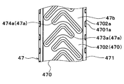
図8Aに示すように、蓄冷材容器47の容器側凸部47aは、左右方向(空気流れ方向)の中心部が両端部よりも鉛直方向上方側に配置された逆V字状に形成されている。そして、逆V字状の容器側凸部47aは、蓄冷材容器47の長手方向、すなわち鉛直方向に沿うように複数並んで配置されている。蓄冷材容器47の一対のプレート部材470の外周部には接合部471が設けられ、接合部471同士が接合されることで、プレート部材4701、4702同士が接合している。一方のプレート部材4701の接合部471は複数の爪部4701aを有し、他方のプレート部材4702の接合部471は複数の切り欠き4702aを有している。図8Cに示すように、複数の爪部4701aが複数の切り欠き4702aにそれぞれ嵌められ、折り曲げられることで、一方のプレート部材4701と他方のプレート部材4702とがカシメ固定されている。この爪部4701aと切り欠き4702aを用いたプレート部材同士の固定方法は、上記第1実施形態および以下の実施形態にも適用可能である。
図8Bに示すように、インナーフィン70の平面部71は、蓄冷材容器47の容器側凸部47aと対応する形状に形成されている。つまり、インナーフィン70の平面部71は、左右方向(空気流れ方向)の中心部が両端部よりも鉛直方向上方側に配置された逆V字状に形成されている。そして、逆V字状の平面部71は、蓄冷材容器47の長手方向、すなわち鉛直方向に沿うように複数並んで配置されている。このとき、隣り合う平面部71を所定距離離して位置づけるインナーフィン70の接続部72は、チューブ45の積層方向(紙面垂直方向)に垂直な断面形状が、左右方向(空気流れ方向)の中心部が両端部よりも鉛直方向上方側に配置された逆V字形状になっている。
図8A、8Bに示すように、蓄冷材容器47の容器側凸部の水平方向に対する傾斜角度と、インナーフィン70の平面部71の水平方向に対する傾斜角度とが等しくなっている。
本実施形態では、蓄冷材容器47の容器側凸部47aにおける鉛直方向の長さが、インナーフィン70の平面部71における鉛直方向の長さと等しくなっている。また、蓄冷材容器47の複数の容器側凸部47aのピッチ(間隔)が、インナーフィン70の複数の平面部71のピッチ(間隔)と等しくなっている。そして、図8Cに示すように、蓄冷材容器47のプレート部材4701、4702における容器側凸部47aの内側表面と、インナーフィン70の平面部71とが面接触をしている。
また、本実施形態では、蓄冷材容器47を構成する一対のプレート部材470のうち、一方のプレート部材4701に形成される容器側凸部47aと、他方のプレート部材4702に形成される容器側凸部47aとは、半ピッチずれて配置されている。すなわち、一方のプレート部材4701の容器側凸部47aは、他方のプレート部材4702の容器側凹部47bと対向しており、また一方のプレート部材4701の容器側凹部47bは、他方のプレート部材4702の容器側凸部47aと対向している。
本実施形態によれば、インナーフィン70の平面部71を、蓄冷材容器47の容器側凸部47aに対応する形状に形成し、蓄冷材容器47の容器側凸部47aの内側表面に、インナーフィン70の平面部71が接合されるようにすることで、インナーフィン70の平面部71と、蓄冷材容器47の容器側凸部47aの内側表面とを面接触させることができる。これにより、蓄冷材容器47の内側表面とのろう付け起点を確保することができるので、蓄冷材容器47とインナーフィン70との接合率を向上させることが可能となる。
ところで、蓄冷材容器の容器側凸部は逆V字状に形成されているが、インナーフィンは空気流れ方向に垂直な断面形状が波形状になっている場合、蓄冷材容器の隣り合う容器側凸部間に形成される容器側凹部よって、インナーフィンと蓄冷材容器とを接合するためのろう材の流れが分断されるおそれがある。
これに対し、本実施形態のように、インナーフィン70の平面部71を、蓄冷材容器47の容器側凸部47aに対応する形状(逆V字状)に形成することで、容器側凹部47bに阻まれることなく、ろう材を流すことができる。これにより、蓄冷材容器47とインナーフィン70とをより確実にろう付けすることが可能となる。
さらに、本実施形態では、蓄冷材容器47の容器側凸部の水平方向に対する傾斜角度と、インナーフィン70の平面部71の水平方向に対する傾斜角度とを等しくしているので、蓄冷材容器47の容器側凸部47aの内側表面と、インナーフィン70の平面部71との接触面積を広くすることができる。このため、蓄冷材容器47とインナーフィン70との接合率をより向上させることが可能となる。
また、本実施形態では、一方のプレート部材4701の爪部4701aは他方のプレート部材4702の切り欠き4702aに嵌め込まれ、折り曲げられている。これにより、爪部4701aの折曲部が接合部471よりも外側に突出する量を低減できる。そのため、空調ユニットに組み付けた際に、蒸発器40と近接して配置される他の部材との干渉を抑制することができる。
(第3実施形態)
次に、本開示の第3実施形態について図9および図10に基づいて説明する。本第3実施形態は、上記第2実施形態と比較して、蓄冷材容器47の内側表面の凹凸形状が異なり、インナーフィンとして第1実施形態のインナーフィン60と同様のものを用いるものである。
(第3実施形態)
次に、本開示の第3実施形態について図9および図10に基づいて説明する。本第3実施形態は、上記第2実施形態と比較して、蓄冷材容器47の内側表面の凹凸形状が異なり、インナーフィンとして第1実施形態のインナーフィン60と同様のものを用いるものである。
図9に示すように、蓄冷材容器47の容器側凸部47aは、空気流れ方向(紙面左右方向)の中心部が両端部よりも鉛直方向上方側に配置された逆V字状に形成されている。そして、逆V字状の容器側凸部47aは、蓄冷材容器47の長手方向、すなわち鉛直方向に沿うように複数並んで配置されている。
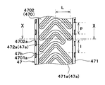
ここで、容器側凸部47aにおける、空気流れ方向中心部から端部までの空気の流れ方向の距離を、リブ長さLという。1つの蓄冷材容器47のプレート部材470に形成される複数の容器側凸部47aのうち、一部の容器側凸部47aのリブ長さLは、他の容器側凸部47aのリブ長さLよりも短くなっている。
このため、図10に示すように、蓄冷材容器47の内側表面のうち、プレート部材4701、4702同士を接合する接合部471近傍に、容器側凹部47bが形成される。そして、この容器側凹部47bの内側表面とインナーフィン60の平面部61とが面接触して、ろう付け起点となる。
ここで、1つの蓄冷材容器47のプレート部材4701、4702に形成される複数の容器側凸部47aのうち、リブ長さLが長い容器側凸部47aを第1容器側凸部471aといい、第1容器側凸部471aよりリブ長さLが短い容器側凸部47aを第2容器側凸部472aという。本実施形態では、1つの蓄冷材容器47のプレート部材470において、第2容器側凸部472aの数は、第1容器側凸部471aの数よりも少ない。
ここで、隣り合う容器側凸部47aの空気流れ方向の中心部同士の間の鉛直方向の距離をリブピッチpという。また、蓄冷材容器47のプレート部材4701、4702に第2容器側凸部472aを設けることにより、接合部471近傍に形成された容器側凹部47bにおける、鉛直方向の長さを平面長さlという。本実施形態では、平面長さlは、リブピッチpよりも長くなっている。
ところで、蓄冷材容器47は、全体を見ると外側へ突出する外凸形状になっており、一対のプレート部材4701、4702の空気流れ方向両端部をかしめてインナーフィン60を封止するために、蓄冷材容器47の中央部においてインナーフィン60とのクリアランスが大きくなりやすい。一方、一対のプレート部材4701、4702のかしめ部近傍、すなわちプレート部材470同士を接合する接合部471近傍は、蓄冷材容器47の剛性が高く、寸法変化が小さい。
したがって、本実施形態のように、蓄冷材容器47の内側表面のうち、接合部471近傍に、容器側凹部47bを設けて、インナーフィン60とのろう付け起点とすることで、蓄冷材容器47とインナーフィン60とを確実にろう付けすることが可能となる。
(第4実施形態)
次に、本開示の第4実施形態について図11に基づいて説明する。本第4実施形態は、上記第3実施形態と比較して、蓄冷材容器47の内側表面の凹凸形状が異なるものである。
(第4実施形態)
次に、本開示の第4実施形態について図11に基づいて説明する。本第4実施形態は、上記第3実施形態と比較して、蓄冷材容器47の内側表面の凹凸形状が異なるものである。
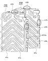
図11に示すように、1つの蓄冷材容器47のプレート部材470に形成される複数の容器側凸部47aのうち、一部の容器側凸部47aは、空気流れ方向一方側(紙面右側)のリブ長さLが、空気流れ方向他方側(紙面左側)のリブ長さLよりも短くなっている。以下、この一部の容器側凸部47aを、第3容器側凸部473aという。
また、1つの蓄冷材容器47のプレート部材470に形成される複数の容器側凸部47aのうち、他の容器側凸部47aは、空気流れ方向一方側(紙面右側)のリブ長さLが、空気流れ方向他方側(紙面左側)のリブ長さLよりも長くなっている。以下、この他の容器側凸部47aを、第4容器側凸部474aという。
1つの蓄冷材容器47のプレート部材470において、第3容器側凸部473aと第4容器側凸部474aとは、鉛直方向に沿って交互に並んで配置されている。
蓄冷材容器47のプレート部材470に第3容器側凸部473aおよび第4容器側凸部474aを設けることで、蓄冷材容器47の内側表面のうち、プレート部材4701、4702同士を接合する接合部471近傍、すなわち蓄冷材容器47の剛性が高い部位に、容器側凹部47bが形成される。このため、本実施形態によれば、上記第3実施形態と同様の効果を得ることが可能となる。
(第5実施形態)
次に、本開示の第5実施形態について図12A、12Bに基づいて説明する。本第5実施形態は、上記第1実施形態と比較して、インナーフィンの形状が異なるものである。
(第5実施形態)
次に、本開示の第5実施形態について図12A、12Bに基づいて説明する。本第5実施形態は、上記第1実施形態と比較して、インナーフィンの形状が異なるものである。
図12Aに示すように、蓄冷材容器47の容器側凸部47aは、空気流れ方向(紙面左右方向)の中心部が両端部よりも鉛直方向上方側に配置された逆V字状に形成されている。そして、逆V字状の容器側凸部47aは、蓄冷材容器47の長手方向、すなわち鉛直方向に沿うように複数並んで配置されている。
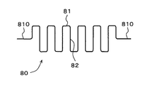
また、インナーフィン80は、図12Bに示すように、チューブ45の積層方向に対して垂直な複数の平面部81と、隣り合う平面部81を所定距離離して位置づける接続部82とを有している。平面部81がチューブ45の長手方向に延びており、インナーフィン80はチューブ45の長手方向に垂直な断面形状が波形状になっている。インナーフィン80の複数の平面部81のうち、空気流れ方向の両端部に配置される平面部(以下、端側平面部810という)は、一対のプレート部材4701、4702同士の間に挟まれている。つまり、一対のプレート部材4701、4702同士を接合する接合部471には、インナーフィン80の端側平面部810が挟み込まれている。換言すると、蓄冷材容器47は、一対のプレート部材470間にインナーフィン80の端側平面部810を挟んだ状態で、一対のプレート部材4701、4702同士を、間に空間を有するように接合することにより、形成されている。複数の平面部81は、端側平面部810以外はチューブ45の積層方向に対して垂直でなくともよく、代わりに山部(頂部)であっても良い。山部は隣り合う山部と接続部82によって接続されている。
本実施形態によれば、一対のプレート部材470間に、インナーフィン80の端側平面部810を挟んだ状態で、一対のプレート部材470同士を、間に空間を有するように接合している。したがって、インナーフィン80の端側平面部810を、蓄冷材容器47を構成する一対のプレート部材470と面接触させることができる。このため、インナーフィン80の端側平面部810において、蓄冷材容器47の内側表面とのろう付け起点を確保することができるので、蓄冷材容器47とインナーフィン80との接合率を向上させることが可能となる。
(第6実施形態)
次に、本開示の第6実施形態について図13に基づいて説明する。本第6実施形態は、上記第1実施形態と比較して、インナーフィン60の形状が異なるものである。
(第6実施形態)
次に、本開示の第6実施形態について図13に基づいて説明する。本第6実施形態は、上記第1実施形態と比較して、インナーフィン60の形状が異なるものである。
図13に示すように、本実施形態のインナーフィン60は、冷却用空気通路460(図5参照)を流通する空気の流れ方向に垂直な断面形状が、平面部61を一方側と他方側に交互に位置させて曲折する波形状であって、空気の流れ方向で、部分的に切り起こされた切り起こし部63を備え、空気の流れ方向から見たときに、切り起こし部63によって形成される波形状部分が、空気の流れ方向で隣接する波形状部分に対してオフセットしているオフセットフィンである。
本実施形態によれば、蓄冷材からインナーフィン60までの距離である相変化距離を短くすることができるので、蓄冷材を短時間で凝固させることが可能となる。
(第7実施形態)
次に、本開示の第7実施形態について図14A、14Bに基づいて説明する。本第7実施形態は、上記第2実施形態と比較して、蓄冷材容器47を形成する一対のプレート部材470の形状が異なるものである。
(第7実施形態)
次に、本開示の第7実施形態について図14A、14Bに基づいて説明する。本第7実施形態は、上記第2実施形態と比較して、蓄冷材容器47を形成する一対のプレート部材470の形状が異なるものである。
図14Aに示すように、一対のプレート部材4701、4702における、チューブ45の長手方向(蓄冷材容器47の長手方向)の端部および空気流れ方向の端部には、一対のプレート部材4701、4702同士を接合する際にプレート部材4701、4702の位置ズレを抑制するための位置ズレ抑制部としての爪部475が設けられている。
本実施形態によれば、爪部475により、一対のプレート部材4701、4702同士を接合する際にプレート部材4701、4702がチューブ45の長手方向および空気流れ方向に位置ズレすることを抑制できる。このため、一対のプレート部材4701、4702同士を接合する際に、蓄冷材容器47の内側表面の凹凸形状とインナーフィン60との位置関係や寸法関係がズレてしまうことを抑制できる。したがって、蓄冷材容器47とインナーフィン60とのろう付け性を向上させ、蓄冷材容器47とインナーフィン60との接合率を向上させることが可能となる。
また、図14Bに示すように、上記第2実施例同様に、複数の爪部4701aを爪部475に設けてもよい。
(他の実施形態)
本開示は上述の実施形態に限定されることなく、本開示の趣旨を逸脱しない範囲内で、以下のように種々変形可能である。
(他の実施形態)
本開示は上述の実施形態に限定されることなく、本開示の趣旨を逸脱しない範囲内で、以下のように種々変形可能である。
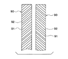
(1)上記第2実施形態では、蓄冷材容器47の内部に、逆V字状の平面部71を有する1つのインナーフィン70を配置した例について説明したが、インナーフィンの構成はこれに限定されない。例えば、図15に示すように、蓄冷材容器47の内部に、左右方向(空気流れ方向)の中心部が端部よりも鉛直方向上方側になるように傾斜した平面部91および接続部92を有する傾斜型のインナーフィン90を、2つ組み合わせて配置してもよい。
(2)上記第2実施形態では、一対のプレート部材470のうち、一方のプレート部材4701aに形成される容器側凸部47aと、他方のプレート部材4702aに形成される容器側凸部47aとを、半ピッチずれて配置した例について説明したが、これに限らず、同一ピッチで配置してもよい。
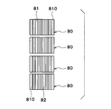
(3)上記第5実施形態では、蓄冷材容器47の内部に、平面部81がチューブ45の長手方向に延びており、チューブ45の長手方向に直交する断面形状が波形状になっている1つのインナーフィン80を配置した例について説明したが、インナーフィン80の構成はこれに限定されない。例えば、図16に示すように、平面部81がチューブ45の長手方向に延びており、チューブ45の長手方向に直交する断面形状が波形状になっている複数のインナーフィン80を、チューブ45の長手方向に沿って複数配置してもよい。
(4)上記第6実施形態では、蓄冷材からインナーフィン60までの距離である相変化距離を短くするために、インナーフィン60としてオフセットフィンを用いた例について説明したが、これに限らず、例えば、インナーフィン60を繊維状(ファイバー状)としてもよい。また第6実施形態のインナーフィン60と同様の形状を上記インナーフィン70、80、90に適用してもよい。
(5)上記第7実施形態では、一対のプレート部材470におけるチューブ45の長手方向の端部および空気流れ方向の端部の双方に、位置ズレ抑制部としての爪部475を設けた例について説明したが、これに限らず、一対のプレート部材470におけるチューブ45の長手方向の端部および空気流れ方向の端部のいずれか一方に、爪部475を設けてもよい。
また、上記実施形態1~7では、一対のプレート部材470(4701、4702)を、間に空間を有するように接合することにより、内部に蓄冷材を収容するための部屋を区画したが、これに限らない。一枚のプレートを折り曲げて、主面を対向接合させることにより、蓄冷材を収容する部屋を区画してもよい。
上記実施形態では、インナーフィン60、70、80、90は、チューブ45の積層方向に対して垂直な複数の平面部61、71、81、91を有していたが、平面部61、71、81、91は曲面を有する山部(頂部)であっても良い。
Claims (7)
- 冷媒通路を有するとともに、互いに間隔を設けて積層配置された複数の冷媒管(45)と、
前記冷媒管(45)に接合されるとともに、蓄冷材を収容する部屋を区画する蓄冷材容器(47)と、
前記蓄冷材への蓄冷時および前記蓄冷材からの放冷時に冷却対象空間を冷却する空気が流通する冷却用空気通路(460)と、
前記蓄冷材容器(47)の内部に配置されるとともに、前記蓄冷材との伝熱面積を増大させるインナーフィン(60、70、80、90)とを備える蓄冷熱交換器であって、
前記インナーフィン(60、70、80、90)は、前記冷媒管(45)の積層方向に対して垂直な複数の平面部(61、71、81、91)を少なくとも有しており、
1つの前記インナーフィン(60、70、80、90)の全ての前記平面部(61、71、81、91)は、それぞれ、前記冷却用空気通路(460)を流通する前記空気の流れ方向における少なくとも一部において、前記蓄冷材容器(47)の内側表面に接合されている蓄冷熱交換器。 - 前記蓄冷材容器(47)は、その内側表面に前記蓄冷材容器(47)の外側に向けて突出した複数の容器側凸部(47a)を有しており、
前記インナーフィン(60、80)の前記平面部(61)は、前記容器側凸部(47a)よりも内方側に位置する前記蓄冷材容器(47)の内側表面に接合されている請求項1に記載の蓄冷熱交換器。 - 前記蓄冷材容器(47)は、その内側表面に前記蓄冷材容器(47)の外側に向けて突出した複数の容器側凸部(47a)を有しており、
前記インナーフィン(70、90)の前記平面部(71、91)は、前記容器側凸部(47a)に対応する形状に形成されており、
前記蓄冷材容器(47)の前記容器側凸部(47a)の内側表面に、前記インナーフィン(70、90)の前記平面部(71、91)が接合されている請求項1に記載の蓄冷熱交換器。 - 前記蓄冷材容器(47)は、その内側表面に前記蓄冷材容器(47)の外側に向けて突出した複数の容器側凸部(47a)を有しており、
前記複数の容器側凸部(47a)のうち、一部の前記容器側凸部(47a)における前記空気の流れ方向の長さは、他の前記容器側凸部(47a)における前記空気の流れ方向の長さよりも短い請求項1ないし3に記載の蓄冷熱交換器。 - 冷媒通路を有するとともに、互いに間隔を設けて積層配置された複数の冷媒管(45)と、
前記冷媒管(45)に接合されるとともに、蓄冷材を収容する部屋を区画する蓄冷材容器(47)と、
前記蓄冷材への蓄冷時および前記蓄冷材からの放冷時に冷却対象空間を冷却する空気が流通する冷却用空気通路(460)と、
前記蓄冷材容器(47)の内部に配置されるとともに、前記蓄冷材との伝熱面積を増大させるインナーフィン(80)とを備える蓄冷熱交換器であって、
前記蓄冷材容器(47)は、一対のプレート部材(470)を有しているとともに、前記一対のプレート部材(470)間に前記蓄冷材を収容する部屋が形成されており、
前記インナーフィン(80)は、前記冷媒管(45)の積層方向に対して垂直な複数の平面部(81)と、隣り合う前記平面部(81)を接続する接続部(82)とを有するとともに、前記冷媒管(45)の長手方向に直交する断面形状が波形状になっており、
前記インナーフィン(80)の前記複数の平面部(81)は、前記冷却用空気通路(460)を流通する前記空気の流れ方向の前記インナーフィン(80)の両端部に配置される端側平面部(810)を有しており、
前記一対のプレート部材(470)間に、前記端側平面部(810)を挟んだ状態で、前記一対のプレート部材(470)同士は、間に前記蓄冷材を収容する前記部屋を有するように接合されている蓄冷熱交換器。 - 冷媒通路を有するとともに、互いに間隔を設けて配置された複数の冷媒管(45)と、
前記冷媒管(45)に接合されるとともに、蓄冷材を収容する部屋を区画する蓄冷材容器(47)と、
前記蓄冷材への蓄冷時および前記蓄冷材からの放冷時に冷却対象空間を冷却する空気が流通する冷却用空気通路(460)と、
前記蓄冷材容器(47)の内部に配置されるとともに、前記蓄冷材との伝熱面積を増大させるインナーフィン(60、70、80、90)とを備える蓄冷熱交換器であって、
前記蓄冷材容器(47)は、前記蓄冷材を収容する前記部屋を間に有するように接合された一対のプレート部材(470)を有しており、
前記一対のプレート部材(470)における、前記冷媒管(45)の長手方向の端部および前記空気の流れ方向の端部のうちの少なくとも一方には、前記一対のプレート部材(47)同士を接合する際に前記プレート部材(47)の位置ズレを抑制する位置ズレ抑制部(475)が設けられている蓄冷熱交換器。 - 冷媒通路を有するとともに、互いに間隔を設けて積層配置された複数の冷媒管(45)と、
前記冷媒管(45)に接合されるとともに、蓄冷材を収容する部屋を区画する蓄冷材容器(47)と、
前記蓄冷材への蓄冷時および前記蓄冷材からの放冷時に冷却対象空間を冷却する空気が流通する冷却用空気通路(460)と、
前記蓄冷材容器(47)の内部に配置されるとともに、前記蓄冷材との伝熱面積を増大させるインナーフィン(60、70、80、90)とを備える蓄冷熱交換器であって、
前記インナーフィン(60、70、80、90)は、波形状に形成されて複数の頂部を有しており、
1つの前記インナーフィン(60、70、80、90)の全ての前記頂部は、それぞれ、前記冷却用空気通路(460)を流通する前記空気の流れ方向における少なくとも一部において、前記蓄冷材容器(47)の内側表面に接合されている蓄冷熱交換器。
Applications Claiming Priority (2)
| Application Number | Priority Date | Filing Date | Title |
|---|---|---|---|
| JP2012162825A JP5849883B2 (ja) | 2012-07-23 | 2012-07-23 | 蓄冷熱交換器 |
| JP2012-162825 | 2012-07-23 |
Publications (1)
| Publication Number | Publication Date |
|---|---|
| WO2014017007A1 true WO2014017007A1 (ja) | 2014-01-30 |
Family
ID=49996835
Family Applications (1)
| Application Number | Title | Priority Date | Filing Date |
|---|---|---|---|
| PCT/JP2013/003663 Ceased WO2014017007A1 (ja) | 2012-07-23 | 2013-06-11 | 蓄冷熱交換器 |
Country Status (2)
| Country | Link |
|---|---|
| JP (1) | JP5849883B2 (ja) |
| WO (1) | WO2014017007A1 (ja) |
Cited By (1)
| Publication number | Priority date | Publication date | Assignee | Title |
|---|---|---|---|---|
| JP2016048147A (ja) * | 2014-08-28 | 2016-04-07 | 株式会社ケーヒン・サーマル・テクノロジー | 蓄冷機能付きエバポレータ |
Families Citing this family (4)
| Publication number | Priority date | Publication date | Assignee | Title |
|---|---|---|---|---|
| JP2017159856A (ja) * | 2016-03-11 | 2017-09-14 | カルソニックカンセイ株式会社 | 蓄冷機能付きエバポレータ |
| CN109070697B (zh) * | 2016-06-01 | 2021-10-08 | 株式会社电装 | 蓄冷热交换器 |
| FR3052549B1 (fr) * | 2016-06-10 | 2019-10-11 | Hutchinson | Echangeur stockeur d'energie thermique |
| JP6926183B2 (ja) * | 2019-12-19 | 2021-08-25 | 東芝電波プロダクツ株式会社 | 放熱器 |
Citations (4)
| Publication number | Priority date | Publication date | Assignee | Title |
|---|---|---|---|---|
| JP2001147090A (ja) * | 1999-11-18 | 2001-05-29 | Sanden Corp | 熱交換器 |
| JP2005337606A (ja) * | 2004-05-27 | 2005-12-08 | Sanden Corp | 積層型熱交換器およびその製造方法 |
| JP2011012947A (ja) * | 2009-06-05 | 2011-01-20 | Denso Corp | 蓄冷熱交換器 |
| JP2012126149A (ja) * | 2010-12-13 | 2012-07-05 | Showa Denko Kk | 蓄冷機能付きエバポレータ |
Family Cites Families (2)
| Publication number | Priority date | Publication date | Assignee | Title |
|---|---|---|---|---|
| JP2003090689A (ja) * | 2001-09-13 | 2003-03-28 | Denso Corp | 蓄冷蓄熱熱交換器 |
| JP5525726B2 (ja) * | 2008-12-26 | 2014-06-18 | 株式会社ケーヒン・サーマル・テクノロジー | 蓄冷機能付きエバポレータ |
-
2012
- 2012-07-23 JP JP2012162825A patent/JP5849883B2/ja not_active Expired - Fee Related
-
2013
- 2013-06-11 WO PCT/JP2013/003663 patent/WO2014017007A1/ja not_active Ceased
Patent Citations (4)
| Publication number | Priority date | Publication date | Assignee | Title |
|---|---|---|---|---|
| JP2001147090A (ja) * | 1999-11-18 | 2001-05-29 | Sanden Corp | 熱交換器 |
| JP2005337606A (ja) * | 2004-05-27 | 2005-12-08 | Sanden Corp | 積層型熱交換器およびその製造方法 |
| JP2011012947A (ja) * | 2009-06-05 | 2011-01-20 | Denso Corp | 蓄冷熱交換器 |
| JP2012126149A (ja) * | 2010-12-13 | 2012-07-05 | Showa Denko Kk | 蓄冷機能付きエバポレータ |
Cited By (1)
| Publication number | Priority date | Publication date | Assignee | Title |
|---|---|---|---|---|
| JP2016048147A (ja) * | 2014-08-28 | 2016-04-07 | 株式会社ケーヒン・サーマル・テクノロジー | 蓄冷機能付きエバポレータ |
Also Published As
| Publication number | Publication date |
|---|---|
| JP2014020757A (ja) | 2014-02-03 |
| JP5849883B2 (ja) | 2016-02-03 |
Similar Documents
| Publication | Publication Date | Title |
|---|---|---|
| JP6183100B2 (ja) | 蓄冷熱交換器 | |
| JP5768480B2 (ja) | 蓄冷熱交換器 | |
| WO2014030306A1 (ja) | 蓄冷熱交換器 | |
| JP5542576B2 (ja) | 蓄冷機能付きエバポレータ | |
| JP5849883B2 (ja) | 蓄冷熱交換器 | |
| WO2014041771A1 (ja) | 熱交換器 | |
| WO2016170751A1 (ja) | 蓄冷熱交換器 | |
| JP5920087B2 (ja) | 蓄冷熱交換器 | |
| JP2017067430A (ja) | 蓄冷熱交換器 | |
| WO2019111849A1 (ja) | 熱交換器 | |
| WO2020110639A1 (ja) | 熱交換器 | |
| JP5772608B2 (ja) | 熱交換器 | |
| WO2020184315A1 (ja) | 熱交換器 | |
| JP6573030B2 (ja) | 蓄冷熱交換器 | |
| JP5381626B2 (ja) | 蓄冷熱交換器 | |
| JP5402527B2 (ja) | 複式熱交換器 | |
| JP6327386B2 (ja) | 蓄冷熱交換器 | |
| JP7151560B2 (ja) | 蓄冷熱交換器 | |
| WO2019208041A1 (ja) | 熱交換器 | |
| JP7159757B2 (ja) | 熱交換器 | |
| JP7226364B2 (ja) | 熱交換器 | |
| WO2017057174A1 (ja) | 蓄冷熱交換器 | |
| JP2018096568A (ja) | 熱交換器 | |
| JP2017106661A (ja) | 熱交換器 | |
| WO2022044741A1 (ja) | 蓄冷熱交換器 |
Legal Events
| Date | Code | Title | Description |
|---|---|---|---|
| 121 | Ep: the epo has been informed by wipo that ep was designated in this application |
Ref document number: 13822965 Country of ref document: EP Kind code of ref document: A1 |
|
| NENP | Non-entry into the national phase |
Ref country code: DE |
|
| 122 | Ep: pct application non-entry in european phase |
Ref document number: 13822965 Country of ref document: EP Kind code of ref document: A1 |