WO2014016891A1 - ヨー制御用ブレーキパッド及びブレーキ部材 - Google Patents
ヨー制御用ブレーキパッド及びブレーキ部材 Download PDFInfo
- Publication number
- WO2014016891A1 WO2014016891A1 PCT/JP2012/068602 JP2012068602W WO2014016891A1 WO 2014016891 A1 WO2014016891 A1 WO 2014016891A1 JP 2012068602 W JP2012068602 W JP 2012068602W WO 2014016891 A1 WO2014016891 A1 WO 2014016891A1
- Authority
- WO
- WIPO (PCT)
- Prior art keywords
- brake pad
- yaw control
- fiber
- fluororesin fiber
- fluororesin
- Prior art date
- Legal status (The legal status is an assumption and is not a legal conclusion. Google has not performed a legal analysis and makes no representation as to the accuracy of the status listed.)
- Ceased
Links
Images


Classifications
-
- F—MECHANICAL ENGINEERING; LIGHTING; HEATING; WEAPONS; BLASTING
- F16—ENGINEERING ELEMENTS AND UNITS; GENERAL MEASURES FOR PRODUCING AND MAINTAINING EFFECTIVE FUNCTIONING OF MACHINES OR INSTALLATIONS; THERMAL INSULATION IN GENERAL
- F16D—COUPLINGS FOR TRANSMITTING ROTATION; CLUTCHES; BRAKES
- F16D69/00—Friction linings; Attachment thereof; Selection of coacting friction substances or surfaces
- F16D69/02—Composition of linings ; Methods of manufacturing
- F16D69/025—Compositions based on an organic binder
- F16D69/026—Compositions based on an organic binder containing fibres
-
- F—MECHANICAL ENGINEERING; LIGHTING; HEATING; WEAPONS; BLASTING
- F16—ENGINEERING ELEMENTS AND UNITS; GENERAL MEASURES FOR PRODUCING AND MAINTAINING EFFECTIVE FUNCTIONING OF MACHINES OR INSTALLATIONS; THERMAL INSULATION IN GENERAL
- F16D—COUPLINGS FOR TRANSMITTING ROTATION; CLUTCHES; BRAKES
- F16D69/00—Friction linings; Attachment thereof; Selection of coacting friction substances or surfaces
- F16D2069/005—Friction linings; Attachment thereof; Selection of coacting friction substances or surfaces having a layered structure
-
- F—MECHANICAL ENGINEERING; LIGHTING; HEATING; WEAPONS; BLASTING
- F16—ENGINEERING ELEMENTS AND UNITS; GENERAL MEASURES FOR PRODUCING AND MAINTAINING EFFECTIVE FUNCTIONING OF MACHINES OR INSTALLATIONS; THERMAL INSULATION IN GENERAL
- F16D—COUPLINGS FOR TRANSMITTING ROTATION; CLUTCHES; BRAKES
- F16D69/00—Friction linings; Attachment thereof; Selection of coacting friction substances or surfaces
- F16D2069/005—Friction linings; Attachment thereof; Selection of coacting friction substances or surfaces having a layered structure
- F16D2069/008—Layers of fibrous materials
-
- F—MECHANICAL ENGINEERING; LIGHTING; HEATING; WEAPONS; BLASTING
- F16—ENGINEERING ELEMENTS AND UNITS; GENERAL MEASURES FOR PRODUCING AND MAINTAINING EFFECTIVE FUNCTIONING OF MACHINES OR INSTALLATIONS; THERMAL INSULATION IN GENERAL
- F16D—COUPLINGS FOR TRANSMITTING ROTATION; CLUTCHES; BRAKES
- F16D2200/00—Materials; Production methods therefor
- F16D2200/0078—Materials; Production methods therefor laminated
-
- F—MECHANICAL ENGINEERING; LIGHTING; HEATING; WEAPONS; BLASTING
- F16—ENGINEERING ELEMENTS AND UNITS; GENERAL MEASURES FOR PRODUCING AND MAINTAINING EFFECTIVE FUNCTIONING OF MACHINES OR INSTALLATIONS; THERMAL INSULATION IN GENERAL
- F16D—COUPLINGS FOR TRANSMITTING ROTATION; CLUTCHES; BRAKES
- F16D2200/00—Materials; Production methods therefor
- F16D2200/0082—Production methods therefor
- F16D2200/0086—Moulding materials together by application of heat and pressure
-
- F—MECHANICAL ENGINEERING; LIGHTING; HEATING; WEAPONS; BLASTING
- F16—ENGINEERING ELEMENTS AND UNITS; GENERAL MEASURES FOR PRODUCING AND MAINTAINING EFFECTIVE FUNCTIONING OF MACHINES OR INSTALLATIONS; THERMAL INSULATION IN GENERAL
- F16D—COUPLINGS FOR TRANSMITTING ROTATION; CLUTCHES; BRAKES
- F16D2200/00—Materials; Production methods therefor
- F16D2200/0082—Production methods therefor
- F16D2200/0091—Impregnating a mat of fibres with a binder
Definitions
- the present invention relates to a brake pad for yaw control and a brake member using the same.
- Patent Document 1 phenol resin molding materials
- Patent Document 2 carbon materials
- Patent Document 3 phenol resin molding materials
- Patent Document 2 carbon materials
- Wind turbine yaw control may be performed using brake pads provided on the wind turbine bearings. A high pressure load is applied to the yaw control brake pad over a long period of time due to the structure of the nacelle of the windmill and the like.
- an object of the present invention is to provide a brake pad for yaw control that has a high compressive strength that can withstand a high load over a long period of time and that has excellent wear resistance.
- the present invention relates to a brake pad for yaw control that includes a fluororesin fiber assembly and a matrix resin impregnated in the fluororesin fiber assembly and includes a braking portion having a braking surface.
- the brake pad according to the present invention has a high compressive strength capable of withstanding a high load over a long period of time, and has excellent wear resistance.
- the ratio of the matrix resin in the braking part may be 20 to 50% by mass based on the total mass of the braking part.
- the fluororesin fiber assembly may be a woven fabric. It is even more advantageous in terms of compressive strength and wear resistance that the brake pad has these configurations.
- the brake pad according to the present invention may further include a base portion that is provided on the opposite side of the braking surface of the braking portion and supports the braking portion.
- the base portion may include a non-fluororesin fiber aggregate and a matrix resin impregnated in the non-fluororesin fiber aggregate.
- the braking unit may further include a non-fluororesin fiber assembly, and the fluororesin fiber assembly and the non-fluororesin fiber assembly may be alternately laminated.
- the non-fluororesin fiber aggregate is formed of at least one fiber selected from cotton, wool, silk, hemp, rayon, nylon, acrylic, vinylon, polyester, polyolefin, polyurethane, aramid, boron, zylon, glass and carbon. It may be an aggregate.
- the brake pad may include 20 to 60 sheet-like fluororesin fiber aggregates, and the fiber aggregates may be laminated.
- the brake pad includes a sheet-like fluororesin fiber aggregate and a sheet-like non-fluororesin fiber aggregate, the total number of the fiber aggregates is 20 to 60, and the fiber aggregates are laminated. Also good.
- the matrix resin is, for example, a cured product of a phenol resin composition or an epoxy resin composition.
- the present invention relates to a wind turbine yaw control brake member including a support member having a recess and a brake pad fitted in the recess.
- the brake member according to the present invention includes the yaw control brake pad according to the present invention.
- FIG. 1 is a cross-sectional view showing an embodiment of a brake pad.
- a brake pad 100 shown in FIG. 1 includes a braking portion 1 having a flat braking surface S, and a base portion 2 that is provided on the opposite side of the braking surface S of the braking portion 1 and supports the braking portion 1.
- the frictional resistance for yaw control is applied to the non-braking member by the contact between the braking surface S of the braking unit 1 and the member to be braked.
- the braking unit 1 includes a plurality of fluororesin fiber reinforced resin layers 10 each having a sheet-like fluororesin fiber aggregate and a matrix resin impregnated therein.
- the fluororesin fiber aggregates included in each fluororesin fiber reinforced resin layer 10 are laminated along a direction perpendicular to their main surfaces.
- the matrix resins of the adjacent fluororesin fiber reinforced resin layers 10 are usually formed integrally with each other, and a clear interface is often not formed between them.
- the brake pad 100 Since the brake part 1 has the fluororesin fiber aggregate and the matrix resin, the brake pad 100 has a wear resistance characteristic equal to or higher than that of a conventional resin material and a carbon sintered body, and is a non-braking member. Even when a high load is applied due to the mass or the like, it can have a low friction coefficient characteristic that does not damage the non-braking member.
- the fluororesin fiber assembly constituting the braking part 1 is mainly composed of fluororesin fibers.
- the fluororesin fiber assembly is made of union, mixed twist, blended cotton, etc. as long as the low friction characteristics of the fluororesin fibers are not impaired.
- Other fiber materials may be included by the method described above.
- the fluororesin fiber assembly and the non-fluororesin fiber assembly described later may be a woven fabric, a knitted fabric, a cross woven fabric, or a felt. By using these forms of fiber assemblies, it is possible to more effectively prevent the brake pads from cracking when a high load is applied. From the viewpoint of the impregnation property of the matrix resin, the fiber assembly may be a woven fabric whose porosity can be easily adjusted.
- fluororesin fibers forming the fluororesin fiber aggregate examples include polytetrafluoroethylene (PTFE) fiber, tetrafluoroethylene-hexafluoropropylene copolymer (FEP) fiber, and tetrafluoroethylene-p-fluoroalkyl vinyl ether copolymer.
- PTFE polytetrafluoroethylene
- FEP tetrafluoroethylene-hexafluoropropylene copolymer
- ETFE ethylene-tetrafluoroethylene copolymer
- the base portion 2 includes a plurality of non-fluorinated resin fiber reinforced resin layers 11 and 12 having a sheet-like non-fluorinated resin fiber aggregate and a matrix resin impregnated therein.
- the non-fluororesin fiber reinforced resin layer 11 and the non-fluororesin fiber reinforced resin layer 12 include different types of non-fluorine resin fibers.
- the brake part 1 in contact with the non-braking member is required to have excellent wear resistance and strength capable of withstanding a high load, whereas the base part 2 is required to have a strength capable of withstanding a high load. Since it does not contact the non-braking member within the period of use, a high degree of wear resistance is not required. For this reason, what is necessary is just to comprise the base
- the brake pad has a two-layer structure of the braking portion 1 and the base portion 2 having different laminated structures, and by using only the braking portion 1 with the fluororesin fiber imparting wear resistance, the expensive fluororesin fiber The amount used can be reduced. This makes it possible to achieve both low cost and high wear resistance.
- the non-fluorinated resin fiber aggregate is made of, for example, at least one fiber selected from cotton, wool, silk, hemp, rayon, nylon, acrylic, vinylon, polyester, polyolefin, polyurethane, aramid, boron, zylon, glass, and carbon.
- Including From the viewpoint of low cost, natural fiber cotton, synthetic fiber polyester, or inorganic fiber glass can be selected.
- natural fiber hemp, synthetic aramid fiber, or inorganic carbon fiber can be selected.
- the matrix resin constituting the brake pad is a cured product of a thermosetting resin composition containing one or more thermosetting resins selected from phenol resins, epoxy resins, vinyl ester resins, unsaturated polyester resins, and the like. It may be a thermoplastic resin selected from polyamide and polyacetal. From the viewpoint of heat resistance, a thermosetting resin composition can be selected.
- the phenol resin has good wettability with the fluororesin fiber.
- Epoxy resins have good adhesion to fibers and also have excellent mechanical properties.
- the composition of the matrix resin of each fiber reinforced resin layer constituting the braking part or the base part may be the same or different.
- a resol type phenol resin for example, a novolac type phenol resin, a resol type phenol resin, or both of them can be used. From the viewpoint of molding stability, a resol type phenol resin can be selected.
- the epoxy resin examples include bisphenol A glycidyl ether type epoxy resin, bisphenol F glycidyl ether type epoxy resin, bisphenol S glycidyl ether type epoxy resin, bisphenol AD glycidyl ether type epoxy resin, phenol novolac type epoxy resin, biphenyl type epoxy resin and cresol. It may be at least one selected from the group consisting of novolak type epoxy resins.
- the content of the matrix resin (ratio of the matrix resin to the total mass of the fiber aggregate and the matrix resin) may be 20 to 50% by mass. When the content of the matrix resin is in the range of 20 to 50% by mass, the strength and the friction characteristics as a brake pad tend to be particularly good. From the same viewpoint, the content of the matrix resin may be 25 to 45% by mass, or 30 to 40% by mass.
- the matrix resin content in the braking portion may be within the above range, or the matrix resin content in the entire brake pad may be within the above range.
- FIG. 2 is also a cross-sectional view showing an embodiment of the brake pad.
- a brake pad 100 shown in FIG. 2 includes a braking portion 1 having a braking surface S, and a base portion 2 that is provided on the opposite side of the braking portion 1 from the braking surface S and supports the braking portion 1.
- the fluororesin fiber reinforcing layers 10 including the fluororesin fiber aggregates and the non-fluororesin fiber reinforcing layers 11 including the non-fluororesin fiber aggregates are alternately stacked.
- the cost reduction can be further reduced by alternately laminating the fluororesin fiber aggregates and the fiber aggregates of other materials.
- the base part 2 of the brake pad 2 shown in FIG. 2 is composed of a plurality of non-fluorinated resin fiber reinforced layers 11.
- FIG. 3 is also a cross-sectional view showing an embodiment of the brake pad.
- the brake pad 100 shown in FIG. 3 is that, in the braking unit 1, the fiber assembly (fiber reinforced resin layer) stacking direction (direction perpendicular to the main surface of each layer) is inclined with respect to the braking surface S. This is different from the brake pad of FIG.
- the fiber assembly (fiber reinforced resin layer) stacking direction direction perpendicular to the main surface of each layer
- the angle (inclination angle) with respect to the braking surface S in the stacking direction of the fiber assembly may be 2 to 90 °. From the viewpoint of molding, if the inclination angle is small, the yield of the molding process can be increased. Therefore, the inclination angle may be 2 to 30 °.
- the brake pad according to the present invention is not limited to the embodiment exemplified above, and can be appropriately modified without departing from the gist of the present invention.
- the base part comprised from a non-fluororesin fiber reinforcement layer does not necessarily need to be provided.
- the laminated structure becomes vertically symmetrical or a structure similar to it, and warps. Reduction effect is obtained.
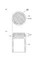
- a brake member 200 shown in FIG. 4 includes a support member 110 having a cylindrical recess 111 and a brake pad 100 according to the present embodiment having a cylindrical shape fitted in the recess 111.
- a plurality of brake members 200 are attached to a wind turbine bearing or the like, and are suitably used as brake members of a yaw control device that tracks the wind turbine rotating surface in a varying wind direction.
- the support member is made of, for example, brass.
- the brake pad (disc pad) incorporated in the brake member receives the load due to the mass of the nacelle and the wind, and also the dynamic load during the yaw operation, so it must be strong and durable enough to withstand this. . Since the brake pad according to the present embodiment is excellent in strength and durability, it can effectively prevent cracking and breakage during long-term use.
- the brake pads wear continuously, it is necessary to replace them regularly, but it is desirable to reduce the frequency of replacement as much as possible. Since the brake pad according to the present embodiment has high wear resistance, the service life is long and the replacement frequency can be reduced. Furthermore, by improving the wear resistance, it is possible to reduce the thickness of the braking portion while maintaining a long life. As a result, the effect of reducing the weight of the brake member, reducing the raw material cost, and reducing the generation of abrasion powder can be obtained.
- PTFE fiber woven fabric cut to a size of 100 mm ⁇ 100 mm (manufactured by Toray Industries, Inc., trade name: Toyoflon (registered trademark), product number: 2402, basis weight: 201 g / m 2 ) and glass fiber woven fabric (manufactured by Nitto Boseki Co., Ltd., The basis weight: 570 g / m 2 ) was dipped in a resol type phenol resin solution (manufactured by Hitachi Chemical Co., Ltd., trade name: VP-51N) and pulled up. The woven fabric impregnated with the resin solution was dried by heating at 110 ° C.
- the matrix resin impregnation ratio after drying was 37% by mass for the prepreg of the PTFE resin fiber woven fabric and 45% by mass for the prepreg of the glass fiber woven fabric.
- the impregnation rate of the matrix resin is a value obtained by subtracting the mass of one woven fabric from the mass of the prepreg after drying as a matrix resin impregnation amount and dividing the matrix impregnation amount by the mass of the entire prepreg.
- the obtained prepreg was used for producing molded articles of the following Examples and Comparative Examples.
- the content ratio of the fiber and the matrix resin is obtained by subtracting the mass of the fiber woven fabric used from the mass of the obtained molded product as the matrix resin content, and the fiber woven fabric or matrix resin content is the mass of the entire molded product. It is the value obtained by dividing.
- the compressive strength test was performed based on JIS-A 1108 by using an Amsler universal testing machine (manufactured by Shimadzu Corporation) and applying a load in the stacking direction of the prepreg to the molded body.
- the compressive strength was 210 MPa.
- a wear test was performed using a ring-on-disk type wear tester (manufactured by Ibaraki Seisakusho Co., Ltd.).
- a ring material: SUS304 (JIS-G 4303: 2005), outer diameter: 34 mm, inner diameter: 25.6 mm, width: 4.2 mm
- the measurement was performed for 8 hours under the conditions of surface pressure: 8 MPa and rotation speed: 0.16 m / s.
- the wear depth per hour was 0.02 mm / h.
- Example 2 17 sheets of PTFE fiber woven fabric prepreg, 1 sheet of glass fiber woven fabric prepreg, 40 sheets of cotton woven fabric prepreg (manufactured by Hitachi Chemical Co., Ltd., trade name: GP-51NS, matrix resin impregnation rate: 60 mass%) And laminated in order.
- the obtained laminate was pressed at 165 ° C. and 8 MPa for 10 minutes using a 300-ton hydraulic molding machine (manufactured by Toho Press Mfg. Co., Ltd.) and then heated at 180 ° C. for 1 hour to control including PTFE fiber woven fabric.
- PTFE resin fiber / glass fiber / cotton fiber / matrix resin 31/5/31/33 (mass%).
- the obtained molded product was subjected to a compressive strength test and an abrasion test in the same manner as in Example 1.
- the compressive strength was 300 MPa, and the wear depth per hour was 0.02 mm / h.
- Example 3 20 sheets of PTFE fiber woven fabric prepregs and 20 cotton woven fabric prepregs were alternately laminated, and 40 cotton woven fabric prepregs were further laminated thereunder.
- the obtained laminate was pressed and heat treated in the same manner as in Example 1, and a control unit (thickness 2.5 mm) in which PTFE fiber woven fabric and cotton fiber woven fabric were alternately laminated, and the cotton woven fabric A molded body composed of laminated base portions (thickness: 4.0 mm) was obtained.
- PTFE resin fiber / cotton fiber / matrix resin 20/45/35 (% by mass).
- the obtained molded product was subjected to a compressive strength test and an abrasion test in the same manner as in Example 1.
- the compressive strength was 280 MPa, and the wear depth per hour was 0.10 mm / h.
- Example 4 Seventeen PTFE fiber woven prepregs, 16 cotton woven prepregs (manufactured by Hitachi Chemical Co., Ltd., trade name: GP-51NS), and 17 PTFE fiber woven prepregs were sequentially laminated.
- the obtained laminate was pressed and heat-treated in the same manner as in Example 1, and a portion where the PTFE fiber woven fabric reinforcing layer was laminated (thickness: 2.5 mm) and a cotton woven fabric reinforced resin layer were laminated.
- a molded body composed of a portion (thickness: 1.7 mm) and a portion (thickness: 2.5 mm) where the PTFE fiber woven fabric reinforcing layer is laminated is obtained.
- PTFE resin fiber / cotton fiber / matrix resin 56/11/33 (mass%).
- the obtained molded product was subjected to a compressive strength test and an abrasion test in the same manner as in Example 1.
- the compressive strength was 230 MPa, and the wear depth per hour was 0.02 mm / h.
- Example 5 30 PTFE fiber woven fabric prepregs and cotton woven fabric prepregs were alternately laminated.
- the obtained laminate was pressed and heat-treated in the same manner as in Example 1 to obtain a molded body.
- the obtained molded body was cut along a direction inclined by 5 ° with respect to the stacking direction, and a portion as a control unit having a thickness of 2.5 mm was cut out.
- 40 pieces of cotton woven fabric prepregs are laminated on this, and the press and heat treatment are performed in the same manner as in Example 1 so that the PTFE fibers and the cotton fibers are alternately laminated while being inclined (thickness 2.5 mm).
- the obtained molded product was subjected to a compressive strength test and an abrasion test in the same manner as in Example 1.
- the compressive strength was 240 MPa, and the wear depth per hour was 0.06 mm / h.
- Comparative Example 2 A carbon sliding material (manufactured by Hitachi Chemical Co., Ltd., trade name: Hitalock HCB-10, Hitalock is a registered trademark) was obtained, and a compressive strength test and an abrasion test were conducted in the same manner as in Example 1.
- the compressive strength was 100 MPa, and the wear depth per hour was 0.17 mm / h.
- Table 1 summarizes the compressive strength and the depth of wear of the molded articles of each Example and Comparative Example.
- Example 6 The compacts produced in Example 2 and Comparative Examples 2 and 3 were cut in the stacking direction to cut out disc-shaped brake pads having a diameter of 80 mm. This brake pad was applied to a brake member having the structure shown in FIG. 4 and used continuously for one year in a windmill. As a result, it was confirmed that the brake pad of Example 2 was free from cracking and chipping and could be used without any problem. On the other hand, the brake pads of Comparative Example 2 and Comparative Example 3 were cracked and chipped after one month of use, and could not be used continuously. Moreover, it was also confirmed that the brake pad of Example 2 has a wear amount that can be used without replacement for two years or more.
Landscapes
- Engineering & Computer Science (AREA)
- General Engineering & Computer Science (AREA)
- Mechanical Engineering (AREA)
- Reinforced Plastic Materials (AREA)
- Braking Arrangements (AREA)
- Laminated Bodies (AREA)
Description
100mm×100mmのサイズにカットしたPTFE繊維織布(東レ株式会社製、商品名:トヨフロン(登録商標)、品番:2402、目付:201g/m2)及びガラス繊維織布(日東紡績株式会社製、目付:570g/m2)をそれぞれレゾール型フェノール樹脂溶液(日立化成工業株式会社製、商品名:VP-51N)に浸漬し、引き上げた。前記樹脂溶液が含浸した織布を、110℃、10分の加熱により乾燥して、PTFE繊維織布、又はガラス繊維織布と、それらに含浸したマトリックス樹脂とを有するプリプレグを得た。乾燥後のマトリックス樹脂含浸率(プリプレグの質量に対するマトリックス樹脂の割合)は、PTFE樹脂繊維織布のプリプレグでは37質量%、ガラス繊維織布のプリプレグでは45質量%であった。マトリックス樹脂の含浸率は、乾燥後のプリプレグ質量から織布一枚の質量を引いた値をマトリックス樹脂含浸量とし、マトリックス含浸量をプリプレグ全体の質量で除して得られる値である。得られたプリプレグを、以下の実施例及び比較例の成形体を作製するために用いた。
(成形体の作製)
PTFE繊維織布プリプレグを50枚積層し、300トン油圧成形機(東邦プレス製作所株式会社製)を用いて、165℃、8MPaで10分プレスした後、180℃で1時間加熱して、フェノール樹脂の硬化物をマトリックス樹脂として含む厚み7.5mmの成形体を得た。得られた成形体のいて、PTFE樹脂繊維/マトリックス樹脂=66/34(質量%)であった。繊維及びマトリックス樹脂の含有率は、得られた成形体の質量から用いた繊維織布の質量を引いた値をマトリックス樹脂含有量とし、繊維織布又はマトリックス樹脂含有量を成形体全体の質量で除して得た値である。
圧縮強度試験は、JIS-A 1108に基づき、アムスラー式万能試験機(株式会社島津製作所製)を用い、成形体に対して、プリプレグの積層方向に荷重を加えることにより行った。圧縮強度は210MPaであった。
リングオンディスク型摩耗試験機(株式会社茨城製作所製)を用いて摩耗試験を行った。50mm×10mm×5mmに切り出したサンプルのPTFE繊維織布側に、リング(材質:SUS304(JIS―G 4303:2005)、外径:34mm、内径:25.6mm、巾:4.2mm)を押しあて、面圧:8MPa、回転速度:0.16m/sの条件で8時間測定した。時間当たりの摩耗深さは0.02mm/hであった。
PTFE繊維織布プリプレグを17枚、ガラス繊維織布プリプレグを1枚、綿織布プリプレグ(日立化成工材株式会社製、商品名:GP-51NS、マトリックス樹脂含浸率:60質量%)を40枚、順番に積層した。得られた積層体を、300トン油圧成形機(東邦プレス製作所株式会社製)を用いて、165℃、8MPaで10分プレスした後、180℃で1時間加熱し、PTFE繊維織布を含む制御部(厚さ2.6mm)と、ガラス繊維織布を含むガラス繊維織布強化層と綿織布を含む綿繊維強化層とからなる基盤部(厚さ:4.0mm)とから構成される成形体を得た。得られた成形体において、PTFE樹脂繊維/ガラス繊維/綿繊維/マトリックス樹脂=31/5/31/33(質量%)であった。
PTFE繊維織布プリプレグと綿織布プリプレグを交互に20枚積層し、さらにその下部に綿織布プリプレグを40枚積層した。得られた積層体を実施例1と同様にプレス及び加熱処理して、PTFE繊維織布と綿繊維織布が交互に積層している制御部(厚さ2.5mm)と、綿織布が積層している基盤部(厚さ4.0mm)とから構成される成形体を得た。得られた成形体において、PTFE樹脂繊維/綿繊維/マトリックス樹脂=20/45/35(質量%)であった。
PTFE繊維織布プリプレグを17枚、綿織布プリプレグ(日立化成工材株式会社製、商品名:GP-51NS)を16枚、PTFE繊維織布プリプレグを17枚、順次積層した。得られた積層体を実施例1と同様にプレス及び加熱処理して、PTFE繊維織布強化層が積層している部分(厚さ:2.5mm)、綿織布強化樹脂層が積層している部分(厚さ1.7mm)及びPTFE繊維織布強化層が積層している部分(厚さ2.5mm)から構成される成形体を得た。得られた成形体において、PTFE樹脂繊維/綿繊維/マトリックス樹脂=56/11/33(質量%)であった。
PTFE繊維織布プリプレグと綿織布プリプレグを交互に30枚積層した。得られた積層体を、実施例1と同様にプレス及び加熱熱処理して、成形体を得た。得れた成形体を、積層方向に対して5°傾いた方向に沿って切断して、厚み:2.5mmの制御部としての部分を切り出した。これに、綿織布プリプレグを40枚積層し、実施例1と同様にプレス及び加熱処理して、PTFE繊維及び綿繊維が傾斜しながら交互に積層している制御部(厚さ2.5mm)と、綿繊維が積層している基盤部(厚さ4.0mm)とから構成される成形体を得た。得られた成形体において、PTFE樹脂繊維/綿繊維/マトリックス樹脂=21/46/33(質量%)であった。
綿繊維織布プリプレグを50枚積層して得た積層体を、実施例1と同様にプレス及び加熱処理して、成形体(綿繊維/マトリックス樹脂=67/33(質量%))を得た。得られた成形体について、実施例1と同様に圧縮強度試験及び摩耗試験を行った。圧縮強度は260MPaであり、時間当たりの摩耗深さは2.0mm/hであった。
カーボン摺動材料(日立化成工業株式会社製、商品名:ヒタロックHCB-10、ヒタロックは登録商標)を入手し、実施例1と同様に圧縮強度試験及び摩耗試験を行った。圧縮強度は100MPaであり、時間当たりの摩耗深さは0.17mm/hであった。
フェノール樹脂(エア・ウォーター株式会社製、商品名:ベルパールS890、ベルパールは登録商標):70質量%と、黒鉛(日本黒鉛工業株式会社製、商品名:CB150):30質量%とを混練した。得られた混錬物を、150℃に熱した金型に入れ、2MPaで5分プレスした後、180℃で8時間処理し、フェノール樹脂成形体を得た。得られた成形体について、実施例1と同様に圧縮強度試験及び摩耗試験を行った。圧縮強度は220MPaであり、時間当たりの摩耗深さは0.40mm/hであった。

実施例2、比較例2、3で作製した成形体を積層方向に切断して、直径80mmの円盤形状のブレーキパッドを切り出した。このブレーキパッドを、図4に示す構成のブレーキ部材に適用し、風車において1年間継続して使用した。その結果、実施例2のブレーキパッドは、割れ、欠けがなく、問題なく使用できることが確認された。一方、比較例2及び比較例3のブレーキパッドは、使用1ヶ月で割れ、欠けが確認され、継続して使用することはできなかった。また、実施例2のブレーキパッドでは、2年以上交換せず使用可能な程度の摩耗量であることも確認された。
Claims (10)
- フッ素樹脂繊維集合体と該フッ素樹脂繊維集合体に含浸したマトリックス樹脂とを含み、制動面を有する制動部を備える、ヨー制御用ブレーキパッド。
- 前記制動部における前記マトリックス樹脂の割合が、前記制動部の全質量を基準として20~50質量%である、請求項1に記載のヨー制御用ブレーキパッド。
- 前記フッ素樹脂繊維集合体が織物である、請求項1又は2に記載のヨー制御用ブレーキパッド。
- 前記制動部の前記制動面とは反対側に設けられた、前記制動部を支持する基盤部を更に備え、
前記基盤部が、非フッ素樹脂繊維集合体と該非フッ素樹脂繊維集合体に含浸したマトリックス樹脂とを含む、
請求項1~3のいずれか一項に記載のヨー制御用ブレーキパッド。 - 前記制動部が、非フッ素樹脂繊維集合体を更に含み、前記フッ素樹脂繊維集合体と前記非フッ素樹脂繊維集合体とが交互に積層されている、請求項1~4のいずれか一項に記載のヨー制御用ブレーキパッド。
- 前記非フッ素樹脂繊維集合体が、綿、毛、絹、麻、レーヨン、ナイロン、アクリル、ビニロン、ポリエステル、ポリオレフィン、ポリウレタン、アラミド、ボロン、ザイロン、ガラス及び炭素から選ばれる少なくとも1種の繊維から形成された集合体である、請求項4又は5に記載のヨー制御用ブレーキパッド。
- シート状の前記フッ素樹脂繊維集合体を20~60枚含み、それら繊維集合体が積層されている、請求項1~6のいずれか一項に記載のヨー制御用ブレーキパッド。
- シート状の前記フッ素樹脂繊維集合体及びシート状の前記非フッ素樹脂繊維集合体を含み、それら繊維集合体の合計数が20~60枚であり、それら繊維集合体が積層されている、請求項1~6のいずれか一項に記載のヨー制御用ブレーキパッド。
- 前記マトリックス樹脂が、フェノール樹脂組成物又はエポキシ樹脂組成物の硬化物である、請求項1~8のいずれか一項に記載のヨー制御用ブレーキパッド。
- くぼみを有する支持部材と、
該くぼみに嵌め込まれた請求項1~9のいずれか一項に記載のヨー制御用ブレーキパッドと、
を備える、風車のヨー制御用ブレーキ部材。
Priority Applications (4)
| Application Number | Priority Date | Filing Date | Title |
|---|---|---|---|
| PCT/JP2012/068602 WO2014016891A1 (ja) | 2012-07-23 | 2012-07-23 | ヨー制御用ブレーキパッド及びブレーキ部材 |
| US14/408,571 US9568061B2 (en) | 2012-07-23 | 2012-07-23 | Brake pad for yaw control, and brake member |
| JP2014526628A JP6056859B2 (ja) | 2012-07-23 | 2012-07-23 | ヨー制御用ブレーキパッド及びブレーキ部材 |
| CN201280074751.7A CN104471270B (zh) | 2012-07-23 | 2012-07-23 | 偏航控制用制动块及制动构件 |
Applications Claiming Priority (1)
| Application Number | Priority Date | Filing Date | Title |
|---|---|---|---|
| PCT/JP2012/068602 WO2014016891A1 (ja) | 2012-07-23 | 2012-07-23 | ヨー制御用ブレーキパッド及びブレーキ部材 |
Publications (1)
| Publication Number | Publication Date |
|---|---|
| WO2014016891A1 true WO2014016891A1 (ja) | 2014-01-30 |
Family
ID=49996728
Family Applications (1)
| Application Number | Title | Priority Date | Filing Date |
|---|---|---|---|
| PCT/JP2012/068602 Ceased WO2014016891A1 (ja) | 2012-07-23 | 2012-07-23 | ヨー制御用ブレーキパッド及びブレーキ部材 |
Country Status (4)
| Country | Link |
|---|---|
| US (1) | US9568061B2 (ja) |
| JP (1) | JP6056859B2 (ja) |
| CN (1) | CN104471270B (ja) |
| WO (1) | WO2014016891A1 (ja) |
Cited By (2)
| Publication number | Priority date | Publication date | Assignee | Title |
|---|---|---|---|---|
| CN105351415A (zh) * | 2015-12-22 | 2016-02-24 | 江西华伍制动器股份有限公司 | 风力发电机偏航制动衬垫及其制备方法 |
| JP2017019886A (ja) * | 2015-07-07 | 2017-01-26 | 日立化成株式会社 | 摺動部材及び風車のヨー制御用ブレーキ部材 |
Families Citing this family (4)
| Publication number | Priority date | Publication date | Assignee | Title |
|---|---|---|---|---|
| EP3028983B1 (de) * | 2014-12-05 | 2018-02-07 | Zollern GmbH & Co. KG | Winde, insbesondere Freifallwinde mit einer Betriebs- und Haltebremse |
| CN107286570B (zh) * | 2017-06-20 | 2018-05-29 | 方达能源集团有限公司 | 偏航刹车片及其制备方法 |
| DE102018216268A1 (de) * | 2017-09-29 | 2019-04-04 | Robert Bosch Gmbh | Additiv hergestellte bremsklotzanordnung mit gesteuertem kompressibilitätsfaktor |
| CN110762141A (zh) * | 2019-09-30 | 2020-02-07 | 广东新志密封技术有限公司 | 风电偏航器制动多层层压摩擦片成型工艺及制品 |
Citations (7)
| Publication number | Priority date | Publication date | Assignee | Title |
|---|---|---|---|---|
| JPH04153291A (ja) * | 1990-10-17 | 1992-05-26 | Oowada Carbon Kogyo Kk | 摩擦材料 |
| JPH04306285A (ja) * | 1991-04-04 | 1992-10-29 | Oowada Carbon Kogyo Kk | 摩擦材料 |
| JPH0762329A (ja) * | 1993-08-24 | 1995-03-07 | Hitachi Chem Co Ltd | 摩擦材用混和物及びそれを用いた摩擦材 |
| JPH0882277A (ja) * | 1994-09-13 | 1996-03-26 | Mitsubishi Heavy Ind Ltd | 風車用ヨーブレーキ |
| JP2003528261A (ja) * | 1999-10-20 | 2003-09-24 | カール−ツァイス−スティフツング | ブレーキシステムに使用される構成部品用摩擦ライニング |
| JP2004232500A (ja) * | 2003-01-28 | 2004-08-19 | Komatsu Ltd | 風力発電設備のナセル旋回駆動装置、及びその運転方法 |
| JP2006518413A (ja) * | 2003-01-24 | 2006-08-10 | バラード マテリアル プロダクツ インコーポレイテッド | 炭素繊維摩擦材料 |
Family Cites Families (13)
| Publication number | Priority date | Publication date | Assignee | Title |
|---|---|---|---|---|
| US2989657A (en) * | 1956-07-23 | 1961-06-20 | Westinghouse Electric Corp | Laminated structure having polyfluoroethylene on one surface thereof |
| JPS4923564A (ja) | 1972-06-23 | 1974-03-02 | ||
| US4045608A (en) * | 1974-09-23 | 1977-08-30 | Todd Robert A | Friction facing with porous sheet base |
| US5646076A (en) * | 1979-12-21 | 1997-07-08 | Bortz; David N. | Friction controlling devices and methods of their manufacture |
| US4999067A (en) * | 1989-02-13 | 1991-03-12 | Erblok Associates | Method for making a hermaphrodite hook and loop fasteners |
| US4997067A (en) * | 1989-06-26 | 1991-03-05 | Fenner America, Inc. | Friction apparatus |
| US5230952A (en) * | 1991-06-17 | 1993-07-27 | Coltec Industries Inc. | Sintered composite friction material comprising fluorocarbon resin |
| JPH05138790A (ja) | 1991-11-19 | 1993-06-08 | Mitsubishi Materials Corp | 摩擦材の製造方法 |
| JP2002348390A (ja) | 2001-05-24 | 2002-12-04 | Daikin Ind Ltd | プリプレグシート及び繊維強化プラスチック成形体 |
| AU2002256901A1 (en) | 2002-05-20 | 2003-12-02 | Du Pont-Toray Co., Ltd. | Shreds for reinforcement, fiber-reinforced product using the shreds, and method of manufacturing the shreds and the product |
| JP2006249129A (ja) | 2005-03-08 | 2006-09-21 | Hitachi Chem Co Ltd | 研磨剤の製造方法及び研磨剤 |
| JP2008001883A (ja) | 2005-11-11 | 2008-01-10 | Hitachi Chem Co Ltd | フェノール樹脂成形材料 |
| CN101956775B (zh) | 2010-05-20 | 2012-08-08 | 湖南博云汽车制动材料有限公司 | 风力发电机用树脂基偏航刹车片及其制备方法 |
-
2012
- 2012-07-23 JP JP2014526628A patent/JP6056859B2/ja not_active Expired - Fee Related
- 2012-07-23 WO PCT/JP2012/068602 patent/WO2014016891A1/ja not_active Ceased
- 2012-07-23 US US14/408,571 patent/US9568061B2/en not_active Expired - Fee Related
- 2012-07-23 CN CN201280074751.7A patent/CN104471270B/zh not_active Expired - Fee Related
Patent Citations (7)
| Publication number | Priority date | Publication date | Assignee | Title |
|---|---|---|---|---|
| JPH04153291A (ja) * | 1990-10-17 | 1992-05-26 | Oowada Carbon Kogyo Kk | 摩擦材料 |
| JPH04306285A (ja) * | 1991-04-04 | 1992-10-29 | Oowada Carbon Kogyo Kk | 摩擦材料 |
| JPH0762329A (ja) * | 1993-08-24 | 1995-03-07 | Hitachi Chem Co Ltd | 摩擦材用混和物及びそれを用いた摩擦材 |
| JPH0882277A (ja) * | 1994-09-13 | 1996-03-26 | Mitsubishi Heavy Ind Ltd | 風車用ヨーブレーキ |
| JP2003528261A (ja) * | 1999-10-20 | 2003-09-24 | カール−ツァイス−スティフツング | ブレーキシステムに使用される構成部品用摩擦ライニング |
| JP2006518413A (ja) * | 2003-01-24 | 2006-08-10 | バラード マテリアル プロダクツ インコーポレイテッド | 炭素繊維摩擦材料 |
| JP2004232500A (ja) * | 2003-01-28 | 2004-08-19 | Komatsu Ltd | 風力発電設備のナセル旋回駆動装置、及びその運転方法 |
Cited By (2)
| Publication number | Priority date | Publication date | Assignee | Title |
|---|---|---|---|---|
| JP2017019886A (ja) * | 2015-07-07 | 2017-01-26 | 日立化成株式会社 | 摺動部材及び風車のヨー制御用ブレーキ部材 |
| CN105351415A (zh) * | 2015-12-22 | 2016-02-24 | 江西华伍制动器股份有限公司 | 风力发电机偏航制动衬垫及其制备方法 |
Also Published As
| Publication number | Publication date |
|---|---|
| CN104471270A (zh) | 2015-03-25 |
| US20150308532A1 (en) | 2015-10-29 |
| CN104471270B (zh) | 2018-01-02 |
| JP6056859B2 (ja) | 2017-01-11 |
| US9568061B2 (en) | 2017-02-14 |
| JPWO2014016891A1 (ja) | 2016-07-07 |
Similar Documents
| Publication | Publication Date | Title |
|---|---|---|
| JP6056859B2 (ja) | ヨー制御用ブレーキパッド及びブレーキ部材 | |
| JP5595705B2 (ja) | 摺動面材及び該摺動面材を備えた複層摺動部材 | |
| JP5859183B2 (ja) | 摺動面材及び該摺動面材を備えた複層摺動部材 | |
| CN102145556A (zh) | 耐高温金属-织物/树脂自润滑轴承复合材料及其制备方法 | |
| JP5691553B2 (ja) | 耐圧摺動部材及びブレーキパッド | |
| EP3021002B1 (en) | Laminate sliding member, and sliding bearing using said laminate sliding member | |
| JP5026216B2 (ja) | 摺動部材用繊維強化樹脂組成物及び積層摺動部材 | |
| JP5249726B2 (ja) | 摺動部材用繊維強化樹脂組成物及び積層摺動部材 | |
| CN111139653A (zh) | 一种自润滑织物及其用途 | |
| EP3189124B1 (en) | Composite bearing with enhanced wear and machinability | |
| JP2005220487A (ja) | フッ素繊維布帛および複合材料 | |
| JP6610042B2 (ja) | 摺動部材及び風車のヨー制御用ブレーキ部材 | |
| JP6182638B1 (ja) | 熱プレス用緩衝材 | |
| JP2004107661A (ja) | 水中用摺動部材ならびにその製造方法 | |
| CN117301649B (zh) | 一种自润滑织物摩擦件结构及其制备方法 | |
| CN109435270B (zh) | 一种船舶轴系端面密封用静环材料及其制备方法 | |
| JP2004091606A (ja) | 水中用摺動部材ならびにその製造方法 | |
| JPS5835468B2 (ja) | ふっ素樹脂交織布積層複合材料およびその製造方法 | |
| CN121183563A (zh) | 一种耐高温高强度低磨损自润滑织物衬垫复合材料及其制备方法和摩擦副 | |
| CZ34163U1 (cs) | Kompozitní deska pro kluzná uložení | |
| JPH11209481A (ja) | Frp成形品及びその製造方法 |
Legal Events
| Date | Code | Title | Description |
|---|---|---|---|
| 121 | Ep: the epo has been informed by wipo that ep was designated in this application |
Ref document number: 12881909 Country of ref document: EP Kind code of ref document: A1 |
|
| ENP | Entry into the national phase |
Ref document number: 2014526628 Country of ref document: JP Kind code of ref document: A |
|
| WWE | Wipo information: entry into national phase |
Ref document number: 14408571 Country of ref document: US |
|
| NENP | Non-entry into the national phase |
Ref country code: DE |
|
| 122 | Ep: pct application non-entry in european phase |
Ref document number: 12881909 Country of ref document: EP Kind code of ref document: A1 |