WO2014014092A1 - 石炭改質方法及び石炭改質装置 - Google Patents
石炭改質方法及び石炭改質装置 Download PDFInfo
- Publication number
- WO2014014092A1 WO2014014092A1 PCT/JP2013/069671 JP2013069671W WO2014014092A1 WO 2014014092 A1 WO2014014092 A1 WO 2014014092A1 JP 2013069671 W JP2013069671 W JP 2013069671W WO 2014014092 A1 WO2014014092 A1 WO 2014014092A1
- Authority
- WO
- WIPO (PCT)
- Prior art keywords
- coal
- gas
- fluidized bed
- classifier
- supplied
- Prior art date
- Legal status (The legal status is an assumption and is not a legal conclusion. Google has not performed a legal analysis and makes no representation as to the accuracy of the status listed.)
- Ceased
Links
Images




Classifications
-
- C—CHEMISTRY; METALLURGY
- C10—PETROLEUM, GAS OR COKE INDUSTRIES; TECHNICAL GASES CONTAINING CARBON MONOXIDE; FUELS; LUBRICANTS; PEAT
- C10B—DESTRUCTIVE DISTILLATION OF CARBONACEOUS MATERIALS FOR PRODUCTION OF GAS, COKE, TAR, OR SIMILAR MATERIALS
- C10B57/00—Other carbonising or coking processes; Features of destructive distillation processes in general
- C10B57/08—Non-mechanical pretreatment of the charge, e.g. desulfurization
- C10B57/10—Drying
-
- C—CHEMISTRY; METALLURGY
- C10—PETROLEUM, GAS OR COKE INDUSTRIES; TECHNICAL GASES CONTAINING CARBON MONOXIDE; FUELS; LUBRICANTS; PEAT
- C10B—DESTRUCTIVE DISTILLATION OF CARBONACEOUS MATERIALS FOR PRODUCTION OF GAS, COKE, TAR, OR SIMILAR MATERIALS
- C10B21/00—Heating of coke ovens with combustible gases
-
- C—CHEMISTRY; METALLURGY
- C10—PETROLEUM, GAS OR COKE INDUSTRIES; TECHNICAL GASES CONTAINING CARBON MONOXIDE; FUELS; LUBRICANTS; PEAT
- C10B—DESTRUCTIVE DISTILLATION OF CARBONACEOUS MATERIALS FOR PRODUCTION OF GAS, COKE, TAR, OR SIMILAR MATERIALS
- C10B53/00—Destructive distillation, specially adapted for particular solid raw materials or solid raw materials in special form
- C10B53/04—Destructive distillation, specially adapted for particular solid raw materials or solid raw materials in special form of powdered coal
-
- C—CHEMISTRY; METALLURGY
- C10—PETROLEUM, GAS OR COKE INDUSTRIES; TECHNICAL GASES CONTAINING CARBON MONOXIDE; FUELS; LUBRICANTS; PEAT
- C10B—DESTRUCTIVE DISTILLATION OF CARBONACEOUS MATERIALS FOR PRODUCTION OF GAS, COKE, TAR, OR SIMILAR MATERIALS
- C10B57/00—Other carbonising or coking processes; Features of destructive distillation processes in general
- C10B57/08—Non-mechanical pretreatment of the charge, e.g. desulfurization
-
- C—CHEMISTRY; METALLURGY
- C10—PETROLEUM, GAS OR COKE INDUSTRIES; TECHNICAL GASES CONTAINING CARBON MONOXIDE; FUELS; LUBRICANTS; PEAT
- C10L—FUELS NOT OTHERWISE PROVIDED FOR; NATURAL GAS; SYNTHETIC NATURAL GAS OBTAINED BY PROCESSES NOT COVERED BY SUBCLASSES C10G OR C10K; LIQUIFIED PETROLEUM GAS; USE OF ADDITIVES TO FUELS OR FIRES; FIRE-LIGHTERS
- C10L9/00—Treating solid fuels to improve their combustion
- C10L9/08—Treating solid fuels to improve their combustion by heat treatments, e.g. calcining
-
- F—MECHANICAL ENGINEERING; LIGHTING; HEATING; WEAPONS; BLASTING
- F26—DRYING
- F26B—DRYING SOLID MATERIALS OR OBJECTS BY REMOVING LIQUID THEREFROM
- F26B17/00—Machines or apparatus for drying materials in loose, plastic, or fluidised form, e.g. granules, staple fibres, with progressive movement
- F26B17/10—Machines or apparatus for drying materials in loose, plastic, or fluidised form, e.g. granules, staple fibres, with progressive movement with movement performed by fluid currents, e.g. issuing from a nozzle, e.g. pneumatic, flash, vortex or entrainment dryers
-
- F—MECHANICAL ENGINEERING; LIGHTING; HEATING; WEAPONS; BLASTING
- F26—DRYING
- F26B—DRYING SOLID MATERIALS OR OBJECTS BY REMOVING LIQUID THEREFROM
- F26B23/00—Heating arrangements
- F26B23/02—Heating arrangements using combustion heating
- F26B23/028—Heating arrangements using combustion heating using solid fuel; burning the dried product
-
- F—MECHANICAL ENGINEERING; LIGHTING; HEATING; WEAPONS; BLASTING
- F26—DRYING
- F26B—DRYING SOLID MATERIALS OR OBJECTS BY REMOVING LIQUID THEREFROM
- F26B3/00—Drying solid materials or objects by processes involving the application of heat
- F26B3/02—Drying solid materials or objects by processes involving the application of heat by convection, i.e. heat being conveyed from a heat source to the materials or objects to be dried by a gas or vapour, e.g. air
- F26B3/06—Drying solid materials or objects by processes involving the application of heat by convection, i.e. heat being conveyed from a heat source to the materials or objects to be dried by a gas or vapour, e.g. air the gas or vapour flowing through the materials or objects to be dried
- F26B3/08—Drying solid materials or objects by processes involving the application of heat by convection, i.e. heat being conveyed from a heat source to the materials or objects to be dried by a gas or vapour, e.g. air the gas or vapour flowing through the materials or objects to be dried so as to loosen them, e.g. to form a fluidised bed
-
- C—CHEMISTRY; METALLURGY
- C10—PETROLEUM, GAS OR COKE INDUSTRIES; TECHNICAL GASES CONTAINING CARBON MONOXIDE; FUELS; LUBRICANTS; PEAT
- C10B—DESTRUCTIVE DISTILLATION OF CARBONACEOUS MATERIALS FOR PRODUCTION OF GAS, COKE, TAR, OR SIMILAR MATERIALS
- C10B47/00—Destructive distillation of solid carbonaceous materials with indirect heating, e.g. by external combustion
- C10B47/28—Other processes
- C10B47/30—Other processes in rotary ovens or retorts
-
- C—CHEMISTRY; METALLURGY
- C10—PETROLEUM, GAS OR COKE INDUSTRIES; TECHNICAL GASES CONTAINING CARBON MONOXIDE; FUELS; LUBRICANTS; PEAT
- C10L—FUELS NOT OTHERWISE PROVIDED FOR; NATURAL GAS; SYNTHETIC NATURAL GAS OBTAINED BY PROCESSES NOT COVERED BY SUBCLASSES C10G OR C10K; LIQUIFIED PETROLEUM GAS; USE OF ADDITIVES TO FUELS OR FIRES; FIRE-LIGHTERS
- C10L2290/00—Fuel preparation or upgrading, processes or apparatus therefore, comprising specific process steps or apparatus units
- C10L2290/06—Heat exchange, direct or indirect
-
- C—CHEMISTRY; METALLURGY
- C10—PETROLEUM, GAS OR COKE INDUSTRIES; TECHNICAL GASES CONTAINING CARBON MONOXIDE; FUELS; LUBRICANTS; PEAT
- C10L—FUELS NOT OTHERWISE PROVIDED FOR; NATURAL GAS; SYNTHETIC NATURAL GAS OBTAINED BY PROCESSES NOT COVERED BY SUBCLASSES C10G OR C10K; LIQUIFIED PETROLEUM GAS; USE OF ADDITIVES TO FUELS OR FIRES; FIRE-LIGHTERS
- C10L2290/00—Fuel preparation or upgrading, processes or apparatus therefore, comprising specific process steps or apparatus units
- C10L2290/08—Drying or removing water
-
- C—CHEMISTRY; METALLURGY
- C10—PETROLEUM, GAS OR COKE INDUSTRIES; TECHNICAL GASES CONTAINING CARBON MONOXIDE; FUELS; LUBRICANTS; PEAT
- C10L—FUELS NOT OTHERWISE PROVIDED FOR; NATURAL GAS; SYNTHETIC NATURAL GAS OBTAINED BY PROCESSES NOT COVERED BY SUBCLASSES C10G OR C10K; LIQUIFIED PETROLEUM GAS; USE OF ADDITIVES TO FUELS OR FIRES; FIRE-LIGHTERS
- C10L2290/00—Fuel preparation or upgrading, processes or apparatus therefore, comprising specific process steps or apparatus units
- C10L2290/54—Specific separation steps for separating fractions, components or impurities during preparation or upgrading of a fuel
- C10L2290/546—Sieving for separating fractions, components or impurities during preparation or upgrading of a fuel
Definitions
- the present invention relates to a coal reforming method and a coal reforming apparatus.
- the present application claims priority based on Japanese Patent Application No. 2012-162080 filed in Japan on July 20, 2012 and Japanese Patent Application No. 2012-162081 filed on July 20, 2012 in Japan, These contents are incorporated herein.
- Patent Document 1 discloses a technique for using sludge as a raw material containing carbon, drying the sludge in a drying furnace, and then treating the sludge as a fuel by treating it in a carbonization furnace (that is, a carbonization furnace). Is disclosed. Patent Document 1 below describes that heat necessary for drying and dry distillation is supplied by burning sludge, auxiliary fuel, the obtained carbide and volatile matter.
- coal with a low water content as a raw material containing carbon
- it can be commercialized as a fuel gas or chemical raw material using volatile components other than those required for drying and dry distillation, Most of the water is used for drying and carbonization, and there is a problem that there is little volatile content available for commercialization.
- the present invention has been made in view of the above problems, and the object of the present invention is to improve efficiency even when a component derived from coal is used as an external fuel accompanying the reforming process.
- An object of the present invention is to provide a coal reforming method and a coal reforming apparatus capable of well reforming coal.
- coal such as subbituminous coal and lignite has a high water content because it has many hydrophilic functional groups such as hydroxyl groups in the components of the coal and easily stores water in pores present in the coal.
- Coal with a high water content can cover the amount of heat required for drying and dry distillation with only the combustion heat of volatile matter, assuming that the heat of combustion of volatile matter generated from coal is used as a heat source for drying and dry distillation. It became clear that there might not be.
- the present inventor does not require a new pre-process even if the coal used is a coal with a high water content. We intensively studied methods that can reform coal more efficiently.
- a fluidized bed drying classifier is used to dry coal that is put into the apparatus, and pulverized coal is recovered from gas containing pulverized coal discharged from the fluidized bed drying classifier, and the recovered pulverized coal is used as a heat source.
- the inventors have conceived that the amount of heat necessary for drying and dry distillation can be secured without adding a new pre-process, and the present invention has been made.
- a coal reforming method includes a step of classifying coarse coal and pulverized coal while drying the coal with a fluidized bed drying classifier; A step of reforming to a dry distillation gas and char; heat obtained by supplying at least a part of the pulverized coal and at least a part of the dry distillation gas to a combustor for combustion, and the fluidized bed drying classifier And supplying as a heat source to at least one of the carbonizers.
- at least part of the exhaust gas discharged from the fluidized bed drying classifier is at least one of the fluidized bed drying classifier and the dry distillation apparatus from the combustor. You may further provide the process mixed with the combustion gas supplied to either.
- the coal reforming method according to (1) or (2) further includes a step of supplying at least a part of the pulverized coal obtained by the fluidized bed drying classifier to the carbonizer. Also good.
- the coal reforming method according to the above (3) after the pulverized coal supplied to the carbonizer is molded alone or together with the coarse coal, the coal is supplied to the carbonizer. You may make it do.
- the dry distillation apparatus is an indirect heating method in which a heated gas is supplied from the outside; You may further provide the process of supplying the said heated gas after being done to the said fluidized bed drying classifier.
- coal reforming method in the coal reforming method according to any one of (1) to (5), at least a part of the exhaust gas discharged from the fluidized bed drying classifier is supplied to the fluidized bed drying classifier. You may further provide the process mixed with the heating gas to be performed.
- an external fuel is used instead of the dry distillation gas of the pulverized coal and the dry distillation gas supplied to the combustor. May be used.
- a coal reforming apparatus includes a fluidized-bed dry classifier that classifies coarse coal and pulverized coal while drying coal; and dry-distills the coarse coal after drying; A carbonizer for reforming to carbonized gas and char; heat supplied by burning at least a part of the carbonized gas and the pulverized coal and burning the carbonized gas and the pulverized coal; And a combustor that supplies at least one of the steam generator and the carbonizer as a heat source. (9) In the coal reforming apparatus according to (8), at least a part of the exhaust gas discharged from the fluidized bed drying classifier is transferred from the combustor to at least the fluidized bed drying classifier and the dry distillation apparatus.
- the coal reforming apparatus according to (10) further includes a molding machine that molds the pulverized coal alone or together with the coarse coal; the pulverized coal obtained from the fluidized bed drying classifier After at least a part of is molded by the molding machine alone or together with the coarse coal, it is supplied to the dry distillation apparatus.
- the dry distillation apparatus is an indirect heating method in which a heating gas is supplied from the outside; discharged from the dry distillation apparatus The heated gas is then fed to the fluidized bed drying classifier; a configuration may be employed.
- the coal reformer according to any one of (8) to (12) at least a part of the exhaust gas discharged from the fluidized bed drying classifier is transferred to the fluidized bed drying classifier. You may employ
- an external fuel is used instead of the dry distillation gas of the pulverized coal and the dry distillation gas supplied to the combustor. May be used.
- a fluidized bed cooling classifier is used to cool char generated by dry distillation, and fine powdered char is recovered from a gas containing fine powder char discharged from the fluidized bed cooling classifier. It was also conceived that the amount of heat required for drying and dry distillation can be maintained without using a pre-process by using the collected fine powder char as a heat source.
- a coal reforming method includes a step of drying coal with a dryer; a step of reforming the coal after drying with a carbonizer to reform to dry distillation gas and char; Separating the fine char while cooling the char with a fluidized bed cooling classifier; and heat obtained by supplying the fine char and at least a part of the dry distillation gas to a combustor for combustion. Supplying as a heat source to at least one of the dryer and the carbonizer.
- the coal reforming method according to (15), wherein the exhaust gas discharged from at least one of the dryer and the fluidized bed cooling classifier is supplied to the fluidized bed cooling classifier as a cooling gas. May be further provided.
- the dry distillation apparatus is an indirect heating method in which a heated gas is supplied from the outside; The method may further include a step of supplying the heated gas after being supplied to the dryer.
- a fluidized bed drying classifier is used as the dryer.
- the method further includes classifying the coal into coarse coal and pulverized coal while drying the coal; and further supplying the pulverized coal to the combustor.
- the coal reforming method according to (19) at least a part of the exhaust gas discharged from the fluidized bed drying classifier is mixed with a heated gas supplied as the heat source to the fluidized bed drying classifier. You may further provide the process to do.
- the coal reforming method according to (19) or (20) further includes a step of supplying at least a part of the pulverized coal obtained from the fluidized bed drying classifier to the dry distillation device. Also good.
- the coal reforming apparatus includes a dryer that dries the coal; a carbonizer that dry-distills the coal after drying and reforms the coal into dry distillation gas and char; A fluidized bed cooling classifier for classifying while cooling the char to separate fine char from the char; and supplying the fine char and at least a part of the dry distillation gas, and burning the dry distillation gas and the fine char And a combustor that supplies heat obtained as a heat source to at least one of the dryer and the carbonizer.
- the exhaust gas discharged from at least one of the dryer and the fluidized bed cooling classifier is supplied to the fluidized bed cooling classifier as a cooling gas.
- At least a part of the exhaust gas discharged from the dryer is at least one of the dryer and the carbonizer from the combustor. It may be configured to be mixed with the combustion gas supplied as the heat source.
- the dry distillation apparatus is an indirect heating method in which a heated gas is supplied from the outside; discharged from the dry distillation apparatus The heated gas is supplied to the dryer; a configuration may be employed.
- fluidized bed drying classification in which the dryer classifies coarse coal and pulverized coal while drying the coal.
- the pulverized coal is supplied to the combustor; a configuration may be employed.
- (29) In the coal reforming apparatus according to (28), at least a part of the exhaust gas discharged from the fluidized bed drying classifier is mixed with a heated gas supplied as the heat source to the fluidized bed drying classifier. You may comprise.
- (30) In the coal reforming apparatus according to (28) or (29) above, a configuration is adopted in which at least a part of the pulverized coal obtained from the fluidized bed drying classifier is supplied to the carbonizer. May be.
- the coal reforming apparatus further includes a molding machine that molds the pulverized coal alone or together with the coarse coal; the pulverized coal obtained from the fluidized bed drying classifier At least a part of is formed by the molding machine alone or together with the coarse coal, and then supplied to the carbonizer; the configuration may be adopted.
- a molding machine that molds the pulverized coal alone or together with the coarse coal; the pulverized coal obtained from the fluidized bed drying classifier At least a part of is formed by the molding machine alone or together with the coarse coal, and then supplied to the carbonizer; the configuration may be adopted.
- an external fuel is used instead of the dry distillation gas of the fine char and the dry distillation gas supplied to the combustor. May be used.
- the dryer used when reforming coal is a fluidized bed drying classifier, and pulverized coal obtained from the fluidized bed drying classifier is used as fuel. By using it, it becomes possible to reform coal more efficiently.
- the cooler used when reforming coal is a fluidized bed cooling classifier, and fine powder char obtained from the fluidized bed cooling classifier is used as fuel. By using it, it becomes possible to reform coal more efficiently.
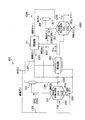
- FIG. 1 is a process flow diagram showing a configuration of a coal reforming apparatus according to the present embodiment
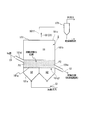
- FIG. 2 is a longitudinal sectional view for explaining a fluidized bed drying classifier of the coal reforming apparatus according to the present embodiment. It is.
- FIG. 3 is a figure which shows an example of the automatic control in the coal reforming apparatus which concerns on this embodiment, Comprising: It is explanatory drawing which shows a part of FIG.
- the coal reforming apparatus 10 receives supply of coal having a particle size distribution (in other words, coal that has not been subjected to prior agglomeration such as briquetting), and dries the supplied coal. And a device for producing char by reforming by dry distillation.
- a particle size distribution in other words, coal that has not been subjected to prior agglomeration such as briquetting
- the coal reforming apparatus 10 includes a fluidized bed drying classifier 101, a carbonizer 103, a dust collector 105, a cooler 107, and a combustor 109. Prepare mainly.
- the drier is an apparatus that heats coal having a particle size distribution supplied to the coal reforming apparatus 10 to remove moisture contained in the coal and dry the coal to a predetermined moisture content.
- a fluidized bed drying classifier 101 is used as a dryer.
- the fluidized bed drying classifier 101 is supplied with a high-temperature gas, for example, about 300 ° C. discharged from the carbonizer 103 as a heating gas G1.
- the fluidized bed drying classifier 101 includes a bottom wall 101a, a side wall 101b, an upper wall 101c, a coal input pipe 101d provided on the side wall 101b, and a dry coal.
- a discharge pipe 101e, a heated gas discharge pipe 101f provided on the upper wall 101c, and a dispersion plate 101g disposed in the internal space S are provided.
- the coal input pipe 101d and the dry coal discharge pipe 101e are provided at positions opposite to each other. In other words, for example, when viewed in the longitudinal sectional view of FIG.
- the coal input pipe 101d is connected to the left side of the paper with respect to the side wall 101b, while the dry coal discharge pipe 101e is on the right side of the paper, which is the opposite side. It is connected. Further, when viewed along the vertical direction, the position of the connection port P1 between the coal input pipe 101d and the side wall 101b is higher than the position of the connection port P2 between the dry coal discharge pipe 101e and the side wall 101b. .
- the heating gas G1 is lowered in the vertical direction.
- Dispersion plate 101g in which a large number of small through holes 101g1 for passing from the top to the bottom are formed.
- the dispersion plate 101g is horizontally arranged at the same height position as the lower end of the connection port P2.
- the dispersion plate 101g has a peripheral edge fixed to the inner peripheral surface of the side wall 101b, and a lower surface supported at a position above the bottom wall 101a.
- the dispersion plate 101g causes the internal space S to dry and classify the input coal C1, and the heated gas taken from the bottom wall 101a directly below the dry classification chamber S1. Is divided into a heated gas supply chamber S2 for receiving the gas.
- the heated gas G1 supplied from the bottom wall 101a which is the bottom of the container constituting the fluidized bed drying classifier 101 passes through the through hole 101g1 provided in the dispersion plate 101g upward from the heated gas supply chamber S2. It flows toward the drying classification chamber S1 that is the upper part in the container, and is discharged from the heated gas discharge pipe 101f that is a discharge part provided on the upper wall 101c above the container.
- Coal C1 having a particle size distribution is fed onto the dispersion plate 101g and is heated in a fluidized state by the heated gas G1 blown upward from the heated gas supply chamber S2 which is the lower part of the container.
- coal C1 is continuously fed into the drying classification chamber S1 through the connection port P1 through the coal charging pipe 101d and stacked on the dispersion plate 101g.
- the heated gas G1 supplied into the heated gas supply chamber S2 passes through the through hole 101g1 from the lower side to the upper side of the dispersion plate 101g.
- the heated gas G1 sent into the dry classification chamber S1 in this way is blown up from the lower layer of the coal C1 stacked on the dispersion plate 101g toward the upper layer.
- the coal C1 flows due to the wind pressure by blowing the heating gas G1, and at the same time, is dried by heating. Therefore, in the fluidized bed drying classifier 101 according to the present embodiment, the heated gas G1 supplied from below the container also functions as a fluidizing gas in addition to the function as the heated drying gas.
- the heating gas G1 supplied into the drying classification chamber S1 of the fluidized bed drying classifier 101 causes the coal C1 in the drying classification chamber S1 to be in a fluid state and is heated by the heating gas G1 to remove contained moisture. It will be done.
- the atmospheric temperature in the drying classifying chamber S1 is maintained at about 100 ° C. by the supplied heating gas G1, and the coal C1 at the outlet of the fluidized bed drying classifier 101 is maintained.
- the supplied coal C1 is heated so that the temperature of the coal reaches about several tens to 100 ° C. (preferably, for example, about 80 to 100 ° C.). Thereby, the water
- the internal temperature of the drying classifying chamber S1 can be controlled according to the flow rate of the heating gas G1 supplied to the fluidized bed drying classifier 101, for example. Further, the water content of the coal C1 at the outlet of the fluidized bed drying classifier 101 is appropriately set according to the target value of the moisture content in the dry coal C2 supplied to the subsequent dry distillation apparatus 103, a predetermined operation rule, and the like. do it.
- the heating gas G1 is supplied to the drying classification chamber S1, and the coal C1 on the dispersion plate 101g becomes a fluid state.
- the fine powder having a particle size of, for example, about 0.3 mm to 0.5 mm contained in the coal C1 (the particle size is a particle size on the premise of sieving and corresponds to a short diameter; the same applies hereinafter).
- Charcoal C3 rides on the heated gas G1 that flows upward in the dry classification chamber S1 and is discharged from the upper part of the fluidized bed dry classifier 101.
- Coarse coal which is a coal having a particle size larger than that of pulverized coal, is finally removed to a predetermined moisture content (for example, a moisture content of 10%, etc.).
- connection port P2 which is a discharge port provided in the vicinity of the dispersion plate 101g, and conveyed to the dry distillation apparatus 103 provided in the subsequent stage.
- the heating gas G2 containing the pulverized coal C3 discharged from the fluidized bed drying classifier 101 is introduced into the dust collector 105 described later, as shown in FIGS.
- the coal C1 containing moisture is dried, and at the same time, the classification process of the coal C1 using the heated gas (fluidized gas) G1.
- the classification process of the coal C1 using the heated gas (fluidized gas) G1. has been done.
- pulverized coal having a predetermined particle size pulverized coal C3 having a particle size equal to or smaller than a predetermined classification point, although a small amount of coal larger than the predetermined classification point is also mixed
- the amount of pulverized coal C3 obtained from the fluidized bed drying classifier 101 is the initial particle size distribution of the coal C1 charged into the fluidized bed drying classifier 101 or the heating gas G1 that is the fluidized gas in the fluidized bed drying classifier 101. It depends on the flow rate.
- the classification point in the fluidized bed drying classifier 101 that is, the target particle size for dividing the coal C1 having a particle size distribution into pulverized coal C3 and coarse coal (dry coal C2) can be adjusted by the flow rate of the fluidized gas. By changing the setting of the classification point by this adjustment, the amount of the pulverized coal C3 discharged from the upper part of the fluidized bed drying classifier 101 can be changed.
- a boiler is separately provided in the middle of the pipe L4 for supplying the heated gas G1 from the dry distillation apparatus 103 to the fluidized bed drying classifier 101. After installing (not shown), high-temperature steam generated by the boiler may be used as the heating gas G1.
- the dry distillation apparatus 103 is an apparatus that feeds dry coal (dry coarse coal) C2 that has been dried by the fluidized bed dry classifier 101 to a predetermined moisture content, and dry-distills the supplied dry coarse coal. .
- a direct heating type dry distillation apparatus such as a circulating fluidized bed or an internal heating rotary kiln may be used, but an indirect heating type dry distillation apparatus such as an external heating rotary kiln may be used. preferable.
- an indirect heating type carbonization device such as an external heating rotary kiln, the heating gas used when carbonizing dry coal C2 is mixed with the carbonization gas consisting of volatiles generated by carbonization of dry coal C2. And the calorific value of the dry distillation gas (including the tar component) can be kept high.
- dry distillation gas D1 such as gas or tar and char C4 are generated.
- the atmospheric temperature inside the dry distillation vessel 103 is about 400 ° C. to 1200 ° C., although it depends on the dry distillation conditions.
- the atmospheric temperature inside the dry distillation apparatus 103 is less than 400 ° C., the pyrolysis reaction of the dry coal C2 does not proceed, and it becomes difficult to generate the dry distillation gas D1 and char C4.
- the atmospheric temperature inside the carbonizer 103 exceeds 1200 ° C., the pyrolysis reaction of the dry coal C2 has been completed and the release of volatile components has also been completed. There is a possibility that the thermal efficiency of will decrease.
- the dry distillation apparatus 103 when using an indirect heating type dry distillation apparatus, such as an external heating type rotary kiln, as the dry distillation apparatus 103, it is preferable to set the atmospheric temperature inside the dry distillation apparatus 103 to 900 ° C. or less because of the structure and material.
- an indirect heating type dry distillation apparatus such as an external heating type rotary kiln
- the char C4 generated by the dry distillation apparatus 103 has a high temperature of about 600 ° C. although it depends on the dry distillation conditions, so that it is transported to the cooler 107 described later and cooled.
- the main component is carbonization gas D1 (tar (a component that becomes liquid at normal temperature), hydrocarbons such as carbon monoxide (CO), hydrogen (H 2 ), and methane (CH 4 ).
- tar a component that becomes liquid at normal temperature
- hydrocarbons such as carbon monoxide (CO), hydrogen (H 2 ), and methane (CH 4 ).
- gases including those that are gases even at room temperature
- At least a part of the produced dry distillation gas D1 is supplied to a combustor 109, which will be described later, and is used as a heat source for heat used in the coal reformer 10.
- a part of the dry distillation gas D1 can also be recovered as a product (product gas or tar).
- the dust collector 105 is a device that separates pulverized coal C3 contained in the exhaust gas G2 discharged from the fluidized bed drying classifier 101 from gas components.
- a cyclone or a bag filter can be used as the dust collector 105 according to the present embodiment.
- the pulverized coal (dry pulverized coal) C3 separated by the dust collector 105 is conveyed to a combustor 109 described later. Further, the gas from which the pulverized coal C3 has been removed is discharged out of the system of the coal reformer 10 as exhaust gas.
- the amount of dry coal C2 conveyed from the fluidized bed dry classifier 101 to the carbonizer 103 is small, or the moisture content of the dry coal C2 at the outlet of the fluidized bed dry classifier 101 is equal to a predetermined value or If lower than that, a part of the pulverized coal C3 recovered by the dust collector 105 may be supplied to the dry distillation apparatus 103 using the pipe L3 shown in FIG. By doing so, operations can be optimized, such as increasing the amount of dry coal C2 supplied to the carbonizer 103, or increasing the water content of the dry coal C2 to a predetermined amount.
- the pulverized coal C3 may be molded or granulated alone or together with the dry coal C2 before being supplied to the dry distillation apparatus 103 by using a molding machine such as a molding machine or a granulator (not shown).
- a molding machine such as a molding machine or a granulator (not shown).
- the “molding” and “granulation” referred to here are included in the “molding” referred to in the present invention. This point is the same in other embodiments and modifications. More specifically, the molding machine or the granulator is installed on the pipe L3, and the dry coal C2 taken out from the fluidized bed drying classifier 101 is molded or molded by the molding machine. In addition to the dry coal C2 that is granulated by a granulator and then transported from the fluidized bed drying classifier 101 to the dry distillation device 103, it may be supplied to the dry distillation device 103.
- the pulverized coal C3 By making the pulverized coal C3 into a molded product or granulated product in advance, it is possible to suppress the generation of dust in the dry distillation apparatus 103 and to reduce the amount of fine powder char scattered along with the dry distillation gas D1. It is possible to improve the recovery rate of the char C4. Molding can be performed by compression molding or extrusion molding, and granulation can be performed by rolling granulation or the like. At that time, a binder such as tar or cement may be added to the pulverized coal C3 in order to improve moldability and granulation.
- a binder such as tar or cement
- the size of the molded product or granulated product is preferably about several mm or more in diameter (corresponding to the minor axis if not spherical) from the viewpoint of suppressing dust generation and preventing scattering.
- the upper limit is not particularly limited, but considering the ease of molding / granulation and handling, and the ease of heat transfer to the inside of the char C4 obtained after dry distillation, the diameter (diameter should be sieved). It is preferable that the diameter is a preliminarily assumed diameter and indicates a minor axis equivalent).
- the size of the molded product or the granulated product is also affected by the ability of the molding machine or the granulator. For example, in the case of briquette molding, a size of about several cm to 10 cm is common.
- the exhaust gas discharged from the dry distillation apparatus 103 is supplied as the heating gas and fluidizing gas (heating gas G1) to the fluidized bed drying classifier 101 .
- at least a part of the exhaust gas discharged from the dust collector 105 is added to the heating gas G1 as a circulating gas and mixed using the pipe L2 shown in FIG. 101 may be supplied.
- the flow rate and temperature of the heated gas G1 supplied to the fluidized bed drying classifier 101 can be easily adjusted. And the coal reforming apparatus 10 can be operated more efficiently.
- the cooler 107 is a device that cools the char C4 generated by the carbonizer 103 to a temperature that is easy to handle.
- a known cooler can be used.
- a cooler of an indirect cooling system such as a rotary kiln, or a direct by water spraying is used.
- a cooling type cooling device, a fluidized bed cooling device, or the like can be used.
- the combustor 109 is a device that creates heat used in the coal reforming apparatus 10 according to the present embodiment.
- the combustor 109 is supplied with at least a part of the dry distillation gas D1 generated by the dry distillation device 103 and pulverized coal (dry pulverized coal) C3 recovered by the dust collector 105 as fuel.
- the combustor 109 generates a high-temperature combustion gas G3 of about 1000 ° C. to 1500 ° C., for example, by burning the dry distillation gas D1 and the pulverized coal C3.
- This combustion gas G3 is introduced into the carbonizer 103 and used as a heat source for advancing the thermal decomposition reaction in the carbonizer 103.
- a combustor for combusting the dry distillation gas D1 and a combustor for combusting the pulverized coal C3 may be provided separately, but the dry distillation gas D1 is combusted. It is preferable to use a common combustor in which a burner (for example, a pulverized coal charging pipe or the like) for charging pulverized coal C3 is installed in the combustion space of the combustor.
- a burner for example, a pulverized coal charging pipe or the like
- the pulverized coal C3 is introduced into the high temperature field where the dry distillation gas D1 is combusting. Therefore, pulverized coal C3 can be easily burned.
- the indirect heating system dry distillation device to which heating gas is supplied from the outside such as an external heating type rotary kiln
- the dry distillation device 103 is used as the dry distillation device 103
- the heated gas discharged from the dry distillation device 103 is fluidized bed drying classifier.
- the dry distillation apparatus 103 serves as the combustor 109.
- the temperature of the combustion gas G3 of about 1000 ° C. to 1500 ° C. discharged from the combustor 109 may be too high.
- a heat exchanger such as a boiler (not shown) is provided in the middle of the pipe L5 for supplying the combustion gas G3 from the combustor 109 to the dry distillation apparatus 103. May be arranged to lower the temperature of the combustion gas G3.
- the coal reforming apparatus 10 according to the present embodiment has been described in detail above with reference to FIGS. 1 and 2.
- the dryer is the fluidized bed drying classifier 101, and the pulverized coal C3 generated from the fluidized bed drying classifier 101 is transferred to the combustor 109. Introduce. Thereby, even when coal having a high water content is used, it is possible to cover the amount of heat necessary for drying and dry distillation without supplying another fuel from the outside.
- coal reformer 10 when using coal with a low water content, it is possible to cover a heat source for drying and carbonizing the coal by combustion of the generated dry distillation gas, but the coal reformer 10 according to the present embodiment is used.
- dry pulverized coal C3 obtained from the fluidized bed drying classifier 101 is introduced into the combustor 109 and burned, thereby reducing the supply amount of the dry distillation gas D1 to the combustor 109. It becomes possible. As a result, the amount of gas and tar recovered as a product can be increased.
- the amount of dry pulverized coal C3 obtained from the fluidized bed drying classifier 101 is the particle size distribution of the coal C1 charged into the coal reformer 10, and the heating supplied into the fluidized bed drying classifier 101.
- the flow rate of the gas G1 when the water content of the coal C1 becomes high and the water content of the dry coal C2 at the outlet of the fluidized bed dry classifier 101 becomes high, the fluidized bed dry classification.
- the dry pulverized coal C3 sent to the combustor 109 is reduced by reducing the flow rate of the heating gas G1 that is a fluidizing gas.
- the amount of dry coal C2 supplied to the dry distillation device 103 and the water content are adjusted by reducing the supply amount or returning the dry pulverized coal C3 to the dry distillation device 103 from the pipe L3 shown in FIG. Can do.
- the dry pulverized coal C3 may be formed alone or together with the dry coal C2 before being supplied to the carbonizer 103.
- the amount of dry pulverized coal C3 recovered by the dust collector 105 is adjusted by using, for example, the fluidized bed drying classifier using the exhaust gas discharged from the dust collector 105 as a circulating gas using the pipe L2 shown in FIG.
- the amount of dry pulverized coal C3 can be increased or decreased by adjusting the flow rate of the fluidizing gas by increasing or decreasing the flow rate of the heating gas G1 by supplying to 101 and increasing or decreasing the supply amount.
- the flow rate of the heating gas G1 supplied from the dry distillation apparatus 103 is increased so that the heating gas G1 can maintain a desired amount of heat even when the circulating gas supplied from the pipe L2 is mixed and the temperature decreases. compensate.
- the fluidized gas supplied to the fluidized bed drying classifier 101 may be performed manually by the operator of the coal reforming apparatus 10, or automatically performed by various control devices (not shown) provided in the coal reforming apparatus 10. May be.
- the following automatic control is performed in the coal reforming method described for the coal reforming apparatus 10. That is, the amount of dry coal C2 supplied from the fluidized bed drying classifier 101 to the carbonizer 103 is measured by the measuring device 202, and the control device grasps this. The control device increases or decreases the supply amount of coal C1 cut out from the supply device 204 to the fluidized bed drying classifier 101 so that the supply amount becomes a constant amount.
- the moisture content of the dry coal C2 at the outlet of the fluidized bed drying classifier 101 is measured by the moisture meter 201, and the control device grasps this.
- the control device controls the pump 206 so that the water content falls within a desired range. That is, when the control device determines that the moisture content is higher than a desired range, the rotational speed of the pump 206 is increased. Thereby, the flow volume of the exhaust gas (circulation gas) which flows through the piping L2 increases, and the flow volume of the heating gas G1 supplied to the fluidized bed drying classifier 101 increases.
- the flow rate of the exhaust gas G2 including the pulverized coal C3 generated in the fluidized bed drying classifier 101 is increased, so that the amount of the pulverized coal C3 obtained by the dust collector 105 is also increased.
- the supply amount by the supply unit 205 is increased until a desired supply amount is obtained.
- the amount of heat of the combustion gas G3 generated in the combustor 109 increases, so the amount of heat of the heated gas G1 supplied to the fluidized bed drying classifier 101 via the pipe L5 and the pipe L4 increases.
- the amount of heat applied to the coal C1 charged into the fluidized bed drying classifier 101 increases, so that the coal C1 can be further dried and the water content of the dry coal C2 can be reduced.
- the meter 203 measures the pulverized coal C3 supplied to the combustor 109 by the feeder 205 so that the amount of pulverized coal C3 is reduced.
- the surplus pulverized coal C3 is supplied to the carbonizer 103 via the pipe L3.
- the flow rate of the exhaust gas (circulation gas) flowing through the pipe L2 is reduced by lowering the rotational speed of the pump 206, and the flow rate of the heating gas G1 supplied to the fluidized bed drying classifier 101 is lowered.
- the amount of pulverized coal C3 supplied to the combustor 109 may be reduced.
- this gas is burned in the combustor 109 and generated.
- the generated combustion gas can be used as a heating gas in the dry distillation apparatus 103, and the generated high calorific value dry distillation gas can be recovered as a product.
- the pulverized coal C3 is burned by the combustor 109, it is possible to reduce the calibration in which the pulverized coal is mixed into the dry distillation gas D1 while operating relatively efficiently.
- the dry distillation gas D1 is recovered by separating it into gas and tar, further decomposing and recovering tar, or recovering by gas reforming or tar reforming. You may do it.
- Examples 1 to 3 and Comparative Example 1 shown below coal having a particle size distribution shown in Table 1 below was used as a raw material.
- a particle size is a particle size on the premise of sieving, and shows a short diameter equivalent.
- Example 1 Roughly pulverized coal C1 (water content: 60%) having a particle size distribution as shown in Table 1 above is charged into the fluidized bed drying classifier 101 at 600 kg / h (240 kg / h excluding moisture), The fluidized bed drying classifier 101 was dried using a heated gas G1 at 350 ° C. and 2600 Nm 3 / h until the water content became 10%. The obtained dry coal C2 was thrown into the dry distillation apparatus 103 which is an external heating type rotary kiln, and was heated up to 600 degreeC, and dry distillation was performed.
- the dry distillation apparatus 103 which is an external heating type rotary kiln, and was heated up to 600 degreeC, and dry distillation was performed.
- Example 1 130 kg / h char, 65 Nm 3 / h gas (CO, H 2 , CH 4 as a main component, heat amount 3450 kcal / Nm 3 gas) and 18 kg / h tar can be obtained.
- the total amount obtained (total amount of gas and tar excluding the product char generated in the carbonizer 103) was sent to the combustor 109 to be combusted to obtain a combustion gas G3 at 1500 ° C.
- 15 kg / h dry pulverized coal C3 recovered from the fluidized bed dry classifier 101 was simultaneously burned.
- the heated gas G1 is cooled by mixing the exhaust gas from the dust collector 105 using the pipe L1 shown in FIG.
- Example 2 Roughly pulverized coal C1 having a particle size distribution as shown in Table 1 (water content: 65%) is charged into the fluidized bed drying classifier 101 at 690 kg / h (240 kg / h excluding moisture), The fluidized bed drying classifier 101 was dried using a heated gas G1 at 320 ° C. and 2800 Nm 3 / h until the water content became 10%. In this drying process, the exhaust gas discharged from the dust collector 105 is mixed with the heated gas G1 using the pipe L2 shown in FIG. 1, and the heated gas G1 is finally increased to 200 Nm 3 / h. It was. The obtained dry coal C2 was heated to 600 ° C.
- the dry distillation apparatus 103 which is an external heating rotary kiln, and dry distillation was performed.
- 125 kg / h char, 62 Nm 3 / h gas (CO, H 2 , CH 4 as a main component, heat amount 3450 kcal / Nm 3 gas) and 17 kg / h tar can be obtained.
- the entire amount obtained was sent to the combustor 109 to be combusted to obtain a combustion gas at 1500 ° C.
- 25 kg / h of dry pulverized coal C2 recovered from the fluidized bed drying classifier 101 was simultaneously combusted.
- Example 2 the heated gas G1 is cooled by mixing the exhaust gas from the dust collector 105 using the pipe L1 shown in FIG.
- dust adhesion hardly occurred and carry-over hardly occurred.
- Example 3 Roughly pulverized coal C1 (water content: 57%) having a particle size distribution as shown in Table 1 above is charged into the fluidized bed drying classifier 101 at 560 kg / h (240 kg / h excluding moisture), In the fluidized bed drying classifier 101, drying was performed using a heated gas G1 at 310 ° C. and 2600 Nm 3 / h until the water content became 10%. The obtained dry coal C2 was heated to 600 ° C. in the dry distillation apparatus 103 which is an external heating rotary kiln, and dry distillation was performed.
- the remaining 9 kg / h dry pulverized coal C3 was subjected to compression molding with a molding machine (not shown in the figure) provided on the pipe L3 in FIG. As a result, it was confirmed that the amount of char recovered (recovery rate) was improved, and the amount of fine powder in the recovered char was smaller than that of the comparative example, and the char was less dusting.
- the heated gas G1 is cooled by mixing the exhaust gas from the dust collector 105 using the pipe L1 shown in FIG.
- the coal reforming method includes a step of classifying the coal C1 into the coarse coal that is the dry coal C2 and the pulverized coal C3 while drying the coal C1 with the fluidized bed drying classifier 101; Is subjected to carbonization by the carbonizer 103 and reformed into the carbonization gas D1 and char C4; at least a part of the pulverized coal C3 and at least a part of the carbonization gas D1 are supplied to the combustor 109 and burned. And supplying the obtained heat as a heat source to at least one of the fluidized bed drying classifier 101 and the dry distillation apparatus 103.
- coal reforming method described in (1) above at least a part of the exhaust gas G2 discharged from the fluidized bed dry classifier 101 is transferred from at least the combustor 109 to the fluidized bed dry classifier 101 and the dry distillation apparatus 103. You may further provide the process mixed with the combustion gas G3 supplied to either one.
- the coal reforming method according to the above (1) or (2) further includes a step of supplying at least a part of the pulverized coal C3 obtained in the fluidized bed drying classifier 101 to the carbonizer 103. Also good.
- the pulverized coal C3 supplied to the dry distillation apparatus 103 is supplied to the dry distillation apparatus 103 after being formed alone or after being formed together with the coarse coal.
- the dry distillation apparatus 103 is an indirect heating method in which a heated gas is supplied from the outside; A step of supplying the heated gas G1 after being supplied to the fluidized bed drying classifier 101 may be further provided.
- the coal reforming method according to any one of (1) to (5) above at least a part of the exhaust gas G2 discharged from the fluidized bed drying classifier 101 is transferred to the fluidized bed drying classifier 101. You may further provide the process mixed with the heating gas G1 supplied.
- the coal reforming apparatus includes a fluidized-bed dry classifier 101 that classifies the coarse coal as dry coal C2 and the fine coal C3 while drying the coal C1, and the coarse particles after drying.
- the coal reforming apparatus according to (8) or (9) is configured such that at least a part of the pulverized coal C3 obtained by the fluidized bed drying classifier 101 is supplied to the carbonizer 103. May be.
- the coal reforming apparatus according to (10) further includes a molding machine that molds the pulverized coal C3 alone or together with the dried coal C2; the pulverized coal C3 obtained from the fluidized bed drying classifier 101; It may be configured that at least a part is supplied to the dry distillation apparatus 103 after being molded by the molding machine alone or after being molded together with the dry coal C2.
- the dry distillation apparatus 103 is an indirect heating method in which a heated gas is supplied from the outside; The heated gas G1 after that is supplied to the fluidized bed drying classifier 101; a configuration may be adopted.
- the coal reforming apparatus according to any one of (8) to (12) at least a part of the exhaust gas G2 discharged from the fluidized bed drying classifier 101 is transferred to the fluidized bed drying classifier 101. You may employ
- the fluidized bed drying classifier 101 is employed as a dryer used when reforming the coal C1, and the pulverized coal C3 obtained from the fluidized bed drying classifier 101 is used as fuel. As a result, the coal C1 can be reformed more efficiently.
- FIG. 4 is a process flow diagram showing the configuration of the coal reforming apparatus 310 according to the present embodiment
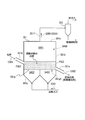
- FIG. 5 is for explaining the fluidized bed cooling classifier 307 of the coal reforming apparatus 310 according to the present embodiment.
- the coal reforming apparatus 310 according to the present embodiment is supplied with coal C301 having a particle size distribution (in other words, coal that has not been subjected to prior agglomeration processing such as briquetting). It is an apparatus for producing char by reforming by drying and dry distillation.
- the coal reformer 310 includes a dryer 301, a carbonizer 303, a boiler 305, a fluidized bed cooling classifier 307, a dust collector 309, and a combustor 311. Prepare for.
- the dryer 301 is an apparatus for removing the moisture contained in the coal C301 to a predetermined amount of water and heating the coal C301 by heating the coal C301 having a particle size distribution supplied to the coal reformer 310. It is.
- the dryer 301 according to this embodiment it is preferable to use an indirect heating type dryer.
- the indirect heating type dryer include tube dryers such as a steam tube dryer (STD) and a call-in tube (Coal-In-Tube: CIT) dryer.
- STD steam tube dryer
- CIT call-in tube
- a high-temperature gas for example, about 300 ° C. discharged from the carbonizer 303, which will be described later, is supplied to the dryer 301 as the heated gas G301.
- the high-temperature gas discharged from the carbonizer 303 may be directly supplied to the dryer 301 as the heated gas G301 without passing through the boiler 305.
- the internal atmospheric temperature is maintained at about 100 ° C. by the supplied heated gas, and the temperature of the dry coal C302 at the outlet of the dryer 301 is about several tens of degrees C. to 100 ° C. (preferably, for example, 80
- the supplied coal C301 is heated so as to be about ⁇ 100 ° C. Thereby, the water
- the temperature of the dry coal C302 at the outlet of the dryer 301 is lower than the lower limit temperature allowed for the equipment design (for example, less than 80 ° C.), water of a predetermined target value or more may remain in the dry coal C302. This is undesirable.
- the temperature of the dry coal C302 at the exit of the dryer 301 greatly exceeds 100 ° C., dry distillation of the dry coal C302 may start, which is not preferable.
- the internal temperature of the dryer 301 can be controlled by adjusting the flow rate of the heated gas G301 supplied to the dryer 301, for example. Further, the moisture content of the dry coal C302 on the outlet side of the dryer 301 can be appropriately set according to the target value of the moisture content in the dry coal C302 supplied to the subsequent dry distillation device 303, a predetermined operation rule, or the like. Good.
- the dry coal C302 from which moisture has been removed to a predetermined moisture content (for example, 10% moisture content) by the dryer 301 is conveyed to a carbonizer 303 provided at a subsequent stage.
- the heated gas G302 discharged from the dryer 301 is processed as exhaust gas.
- the pipe L301 shown in FIG. 4 at least a part of the heated gas G302 is transferred from a combustor 311 to be described later to a dry distillation device. You may mix with the combustion gas G303 supplied to 303.
- FIG. In this case, adjusting the amount of exhaust gas from the pipe L301 makes it easier to control the carbonization temperature of the carbonizer 303, which is more preferable.
- the dry-coalter 303 is a device that receives dry coal C302, which is coal dried to a predetermined moisture content by the dryer 301, and carbonizes the supplied dry coal C302.
- a direct heating system such as a circulating fluidized bed or an internal heating rotary kiln may be used, but an indirect heating system such as an external heating rotary kiln may be used. preferable.
- an indirect heating-type dry kiln such as an external heating type rotary kiln, the heating gas used when dry-drying the dry coal C302 is mixed with the dry-distillation gas D301 made of volatile matter generated by the dry distillation of the dry coal C302. It becomes possible to prevent this, and the calorific value of the dry distillation gas D301 (including the tar component) can be kept high.
- a combustion gas G303 generated by combustion of a substance in a combustor 311 to be described later is supplied to the carbonizer 303 as a heated gas, and dry distillation of the dry coal C302 proceeds by the supplied combustion gas G303, and gas or A dry distillation gas D301 such as tar and a char C304 are generated.
- the atmospheric temperature inside the carbonizer 303 is about 400 ° C. to 1200 ° C. depending on the carbonization conditions.
- the atmospheric temperature inside the carbonizer 303 is lower than 400 ° C., the pyrolysis reaction of the dry coal C302 does not proceed, and it becomes difficult to generate the carbonized gas D301 and char C304.
- the atmospheric temperature inside the carbonizer 303 exceeds 1200 ° C., the pyrolysis reaction of the dry coal C302 has been completed, and the release of volatile matter has also been completed. There is a possibility that the thermal efficiency of will decrease.
- the atmospheric temperature inside the kiln 303 it is preferable to set the atmospheric temperature inside the kiln 303 to 900 ° C. or less because of the structure and material.
- the char C304 generated by the carbonizer 303 has a temperature of about 600 ° C. although it depends on the carbonization conditions, so that it is transported to the cooler 307 to be described later and cooled.
- the main component is carbonization gas D301 (tar (a component that becomes liquid at room temperature), hydrocarbons such as carbon monoxide (CO), hydrogen (H 2 ), and methane (CH 4 ).
- CO carbon monoxide
- H 2 hydrogen
- CH 4 methane
- gases including those that are gases even at room temperature
- At least a part of the produced dry distillation gas D301 is supplied to a combustor 311 described later and burned, and used as a heat source of heat used in the coal reformer 310.
- a part of the dry distillation gas D301 can be recovered as a product.
- the cooler 307 is a device that cools the char C304 generated by the carbonizer 303 to a temperature that is easy to handle.
- a fluidized bed cooling classifier is used as the cooler 307 (hereinafter referred to as a fluidized bed cooling classifier 307).
- the fluidized bed drying classifier 307 includes a bottom wall 307a, a side wall 307b, an upper wall 307c, a high-temperature char charging pipe 307d provided on the side wall 307b, and a cooling unit, which form a container that forms the internal space 300S.
- a rear char discharge pipe 307e, a cooling gas discharge pipe 307f provided on the upper wall 307c, and a dispersion plate 307g disposed in the internal space 300S are provided.
- the high temperature char charging pipe 307d and the cooled char discharging pipe 307e are provided at positions opposite to each other.
- the high-temperature char input pipe 307 d is connected to the left side of the paper with respect to the side wall 307 b, while the post-cooling char discharge pipe 307 e is the opposite side. Connected to the right side. Furthermore, when viewed along the vertical direction, the position of the connection port P301 between the high temperature char input pipe 307d and the side wall 307b is higher than the position of the connection port P302 between the char discharge pipe 307e after cooling and the side wall 307b. ing.
- the cooling gas G307 is moved upward from the bottom in the vertical direction.
- a dispersion plate 307g is provided in which a large number of small through holes 307g1 for passage are formed.
- the dispersion plate 307g is horizontally disposed at the same height as the lower end of the connection port P302.
- the dispersion plate 307g has a peripheral edge fixed to the inner peripheral surface of the side wall 307b, and a lower surface supported at a position above the bottom wall 307a.
- the internal space 300S cools and classifies the charged high temperature char C304, and the cooling gas taken from the bottom wall 307a directly below the cooling classification chamber S301. It is partitioned into a cooling gas supply chamber S302 that receives G307.
- the cooling gas G307 supplied from the bottom wall 307a which is the bottom of the container forming the fluidized bed cooling classifier 307 passes through the through holes 307g1 provided in the dispersion plate 307g from the cooling gas supply chamber S302 toward the cooling classification chamber S301. It passes toward the cooling classification chamber S301, which is the upper part in the container, and is discharged from the cooling gas discharge pipe 307f, which is a discharge part provided on the upper wall 307c above the container.
- the high-temperature char C304 generated by the dry distillation apparatus 303 is fed onto the dispersion plate 307g and becomes a fluid state by the cooling gas G307 blown upward from the cooling gas supply chamber S302 which is the lower part of the container. Is done.
- the high temperature char C304 is introduced into the cooling classification chamber S301 through the connection port P301 through the high temperature char introduction pipe 307d and laminated on the dispersion plate 307g.
- the cooling gas G307 supplied into the cooling gas supply chamber S302 passes through the through hole 307g1 from the lower side to the upper side of the dispersion plate 307g.
- the cooling gas G307 sent into the cooling classification chamber S301 in this way is blown up from the lower layer of the high temperature char C304 stacked on the dispersion plate 307g toward the upper layer.
- the cooling gas G307 supplied from below the container also functions as a fluidizing gas.
- the cooling gas G307 (ie, fluidizing gas) supplied to the fluidized bed cooling classifier 307 is a gas that does not contain oxygen in order to prevent the high temperature char C304 from burning inside the fluidized bed cooling classifier 307. It is preferable to use (for example, nitrogen gas).
- the cooling gas G307 in this embodiment is supplied to the fluidized bed cooling classifier 307 from a gas supply device (not shown).
- a gas supply device not shown.
- the exhaust gas from the dust collector 309 may be returned to the fluidized bed cooling classifier 307, or (2) the exhaust gas G302 from the dryer 301.
- both the exhaust gas from the dust collector 309 and the exhaust gas G302 from the dryer 301 may be supplied to the fluidized bed cooling classifier 307.
- the exhaust gas G302 from the dryer 301 it may be supplied after cooling to a predetermined temperature, if necessary.
- the high temperature char C304 in the cooling classification chamber S301 flows by the cooling gas G307 supplied to the fluidized bed cooling classifier 307, but the fine char C306 having a particle size of about 0.3 mm to 0.5 mm is It rides on the cooling gas G307 flowing upward in the cooling classification chamber S301 in the vertical direction and is discharged from the cooling gas discharge pipe 307f on the upper wall 307c.
- the cooled char C305 having a particle size larger than the fine char C306 is discharged from a discharge port (connection port P302) provided in the vicinity of the dispersion plate 307g of the fluidized bed cooling classifier 307.
- the high temperature char C304 is cooled and the high temperature char C304 is classified using the cooling gas G307 (fluidized gas).
- classification treatment removes fine powder char C306 having a predetermined particle size (fine powder char having a particle size equal to or smaller than a predetermined classification point, but a small amount of char larger than the classification point is also mixed). It is possible to reduce the ratio of fine powder mixed in the char C305 after cooling collected as a product, and it is possible to efficiently reduce the dust generation of the manufactured char. Further, by removing the fine char C306 from the high temperature char C304, it becomes possible to further suppress or prevent clogging of the pipe that may occur in the pipe that transports the manufactured cooled char C305.
- the amount of the fine char C306 obtained from the fluidized bed cooling classifier 307 is the initial particle size distribution of the coal C301 input to the coal reformer 310 or the flow rate of the cooling gas G307 that is the fluidized gas in the fluidized bed cooling classifier 307. (Flow rate).
- the classification point (the target particle size for dividing the high temperature char C304 having a particle size distribution into the fine char C306 and the cooled char C305 having a larger particle size than the fine char C306) can be adjusted by increasing or decreasing the flow rate of the cooling gas G307. Yes, by changing the setting of the classification point, the ratio of the fine char C306 discharged from the upper part of the fluidized bed cooling classifier 307 to the high temperature char C304 can be changed.
- the cooling gas G308 including the fine char C306 discharged from the fluidized bed cooling classifier 307 is introduced into the dust collector 309 as shown in FIGS.
- the dust collector 309 is a device that separates the fine char C306 contained in the introduced cooling gas G308 from gas components.
- a cyclone or a bag filter can be used as the dust collector 309 according to the present embodiment.
- the fine char C306 separated by the dust collector 309 is conveyed to a combustor 311 described later.
- the gas from which the fine char C306 has been removed is discharged out of the system as exhaust gas.
- the combustor 311 is an apparatus that creates heat used in the coal reforming apparatus 310 according to the present embodiment.
- the combustor 311 is supplied with at least a part of the dry distillation gas D301 generated by the dry distillation device 303 and fine powder char C306 collected by the dust collector 309 as fuel.
- the combustor 311 generates a combustion gas G303 having a high temperature of, for example, about 1000 ° C. to 1500 ° C. by burning the dry distillation gas and the fine powder char.
- This combustion gas G303 is introduced into the carbonizer 303 and used as a heat source for advancing the thermal decomposition reaction in the carbonizer 303.
- a combustor for combusting the dry distillation gas D ⁇ b> 301 and a combustor for combusting the fine powder char C ⁇ b> 306 may be provided separately, but combustion of the combustor for combusting the dry distillation gas D ⁇ b> 301 is performed. It is preferable to use a common combustor in which a burner (for example, a char charging pipe or the like) for charging fine powder char C306 is installed in the space.
- a burner for example, a char charging pipe or the like
- the high temperature field where the combustible dry distillation gas D301 is generally combusted is used.
- Fine powder char C306 can be introduced, and fine char char C306 can be easily burned.
- an indirect heating type dry distillation apparatus in which heated gas is supplied from the outside such as an external heating rotary kiln is used as the dry distillation apparatus 303, and the heated gas G301 discharged from the dry distillation apparatus 303 is supplied to the drying apparatus 301.
- the dry distillation apparatus 303 may serve as the combustor 311.
- the temperature of the combustion gas discharged from the combustor 311 of about 1000 ° C to 1500 ° C may be too high.
- a heat exchanger such as a boiler is disposed in the middle of the pipe L302 for supplying the combustion gas G303 from the combustor 311 and the combustion gas G303.
- the temperature may be lowered.
- coal C301 having a high water content is used as a raw material, even if the dry distillation gas D301 generated by the dry distillation device 303 is used, heat necessary for drying and dry distillation may not be provided.
- the fluidized bed cooling classifier 307 is adopted as the cooler, and the fine powder char C306 classified by the fluidized bed cooling classifier 307 is combusted. 311 is introduced. As a result, even when coal C301 having a high water content is used, the amount of heat necessary for drying and dry distillation can be covered without supplying another fuel from the outside.
- coal C301 having a low water content when used as a raw material, it is possible to cover the heat source for drying and dry distillation by burning the generated dry distillation gas D301, but the coal reforming according to the present embodiment
- the fine char char C306 discharged from the fluidized bed cooling classifier 307 is also introduced into the combustor 311 and combusted, whereby the amount of dry distillation gas D301 supplied to the combustor 311 is reduced. It becomes possible to reduce. As a result, it is possible to increase the amount of gas, tar, etc. recovered as a product.
- the amount of fine powder C306 obtained from the fluidized bed cooling classifier 307 includes the initial particle size distribution of the coal C301 input to the coal reformer 310 and the cooling gas supplied to the fluidized bed cooling classifier 307. Although it is determined by the flow rate of G307, when the moisture content of coal C301 becomes high and the moisture content of dry coal C302 at the outlet of dryer 301 becomes high, cooling gas G307 which is a fluidized gas is used. The required amount of heat can be generated by increasing the amount of fine powder char C306 sent to the combustor 311 and increasing the amount of combustion.
- the flow rate of the cooling gas G307 which is a fluidized gas, is reduced to reduce the amount of fine char C306 sent to the combustor 311.
- the amount of heat given from the combustor 311 to the carbonizer 303 can be suppressed.
- the amount of dry coal C302 supplied to the carbonizer 303 and the water content can be adjusted.
- the operator of the coal reformer 310 may manually perform the grasping of the moisture content of the dry coal C302 on the outlet side of the dryer 301 and the flow rate control of the cooling gas G307 in the fluidized bed cooling classifier 307. However, it may be automatically performed by various control devices (not shown) provided in the coal reformer 310.
- FIG. 6 is a process flow diagram showing a coal reforming apparatus 310A according to this modification. Note that portions not included in the following description are the same as those in the second embodiment, and thus description thereof is omitted.
- the cooling gas G307 supplied to the fluidized bed cooling classifier 307 is separated from the fine char char C306 by the dust collector 309 and then discharged out of the system as exhaust gas. It was.
- the coal reforming apparatus 310 ⁇ / b> A according to this modification it is possible to circulate and use the cooling gas G ⁇ b> 307 supplied to the fluidized bed cooling classifier 307 as described below.
- the gas discharged from the dust collector 309 and separated from the fine char C306 is again fluidized bed cooling classified using the pipe L302 shown in FIG.
- the cooling gas G307 is supplied to the vessel 307.
- a part of the exhaust gas G302 discharged from the dryer 301 is supplied to the fluidized bed cooling classifier 307 using the pipe L303. You may supply as G307.
- the fluidized bed It becomes possible to easily adjust the flow rate of the cooling gas G307 supplied to the cooling classifier 307.
- the flow rate of the cooling gas G307 is increased or decreased by increasing or decreasing the supply amount of the exhaust gas supplied to the fluidized bed cooling classifier 307, and as a result, the flow rate of the fluidizing gas is adjusted.
- the amount can be increased or decreased.
- the temperature of the exhaust gas from the dust collector 309 or the temperature of the exhaust gas from the dryer 301 is higher than a predetermined temperature and is not suitable for use as the cooling gas G307, it is in the middle of the pipe L302 or the pipe L303.
- a known cooler (not shown) may be provided to lower the temperature to such an extent that it can be used as the cooling gas G307.
- the cooler provided in the subsequent stage of the dry distillation apparatus 303 is the fluidized bed cooling classifier 307.
- the dryer provided in the previous stage of the dry distillation device 303 is a dryer using a fluidized bed (fluidized bed drying classifier 351).
- the coal reforming apparatus 410 according to the present embodiment will be described with reference to FIGS. 7 and 8. In the following description, differences from the second embodiment will be mainly described.
- the coal reforming apparatus 410 includes a fluidized bed drying classifier 351, a carbonizer 303, a fluidized bed cooling classifier 307, dust collectors 309 and 353, and a combustion And 311 mainly.
- the carbonizer 303 Regarding the carbonizer 303, the fluidized bed cooling classifier 307, the dust collector 309, and the combustor 311 included in the coal reformer 410 according to the present embodiment, the carbonizer of the coal reformer 310 described in the second embodiment. 303, the fluidized bed cooling classifier 307, the dust collector 309, and the combustor 311 have the same configuration and exhibit the same effects, and thus detailed description thereof will be omitted below.
- the dryer heats the coal C301 having a particle size distribution supplied to the coal reforming apparatus 410, thereby removing moisture contained in the coal C301 to a predetermined moisture content, Is a device for drying.
- a fluidized bed drying classifier 351 is used as a dryer.
- the fluidized bed drying classifier 351 includes a bottom wall 351a, a side wall 351b, an upper wall 351c, a coal input pipe 351d provided on the side wall 351b, and dry coal, which form a container forming the internal space S400.
- a discharge pipe 351e, a heated gas discharge pipe 351f provided on the upper wall 351c, and a dispersion plate 351g disposed in the internal space S400 are provided.
- the coal input pipe 351d and the dry coal discharge pipe 351e are provided at positions opposite to each other. In other words, for example, when viewed in the longitudinal sectional view of FIG.
- the coal input pipe 351d is connected to the left side of the paper with respect to the side wall 351b, while the dry coal discharge pipe 351e is on the right side of the paper. It is connected. Further, when viewed along the vertical direction, the position of the connection port P351 between the coal input pipe 351d and the side wall 351b is higher than the position of the connection port P352 between the dry coal discharge pipe 351e and the side wall 351b. .
- a dispersion plate 351g having a large number of small through holes 351g1 is provided in the internal space S400 of the fluidized bed drying classifier 351, as shown in the longitudinal sectional view of FIG. 8, in order to fluidize the input coal C301, the heating gas G301 is passed.
- a dispersion plate 351g having a large number of small through holes 351g1 is provided in order to fluidize the input coal C301.
- the dispersion plate 351g is horizontally arranged at the same height as the lower end of the connection port P352.
- the dispersion plate 351g has a peripheral edge fixed to the inner peripheral surface of the side wall 351b and a lower surface supported at a position above the bottom wall 351a.
- the dispersion plate 351g causes the internal space S400 to dry-classify the coal C301 that has been charged, and the heated gas that has been taken in from the bottom wall 351a directly below the dry-classification chamber S401. It is partitioned into a heated gas supply chamber S402 that receives G301.
- Coal C301 having a particle size distribution is fed onto the dispersion plate 351g and heated in a fluidized state by the heated gas G301 blown upward from the heated gas supply chamber S402 which is the lower part of the container.
- coal C301 is continuously fed into the drying classification chamber S401 from the connection port P351 through the coal charging pipe 351d and stacked on the dispersion plate 351g.
- the heating gas G301 supplied into the heating gas supply chamber S402 passes through the through hole 351g1 from the lower side to the upper side of the dispersion plate 351g.
- the heated gas G301 sent into the drying classification chamber S401 is blown up from the lower layer of the coal C301 stacked on the dispersion plate 351g toward the upper layer.
- the coal C301 flows due to the wind pressure by the blowing of the heating gas G301, and at the same time is dried by heating. Therefore, in the fluidized bed drying classifier 351 according to the present embodiment, the heated gas G301 supplied from below the container also functions as a fluidizing gas in addition to the function as the heated drying gas.
- the heated gas G301 supplied to the fluidized bed drying classifier 351 causes the coal C301 in the fluidized bed drying classifier 351 to be in a fluidized state, and the contained moisture is removed by being heated by the heated gas G301.
- the internal gas temperature is maintained at about 100 ° C. by the supplied heating gas G301, and the temperature of the coal C302 at the outlet of the fluidized bed drying classifier 351 is several.
- the supplied coal C301 is heated so as to be about 10 to 100 ° C. (preferably, for example, about 80 to 100 ° C.). Thereby, the water
- the moisture exceeding the predetermined target value in the dry coal C302 May remain, which is not preferable.
- the temperature of the dry coal C302 at the exit of the fluidized bed drying classifier 351 greatly exceeds 100 ° C., the dry distillation of the dry coal C302 may start, which is not preferable.
- the internal temperature of the fluidized bed drying classifier 351 can be controlled by the flow rate of the heated gas G301 supplied to the fluidized bed drying classifier 351, for example. Further, regarding the moisture content of the dry coal C302 on the outlet side of the fluidized bed drying classifier 351, the target value of the moisture amount required in the dry coal C302 when supplying to the subsequent dry distillation device 303, a predetermined operation rule, etc. What is necessary is just to set suitably according to.
- pulverized coal C303 having a particle size of about 0.3 mm to 0.5 mm is converted into a fluidized bed drying classifier. It rides on the heated gas G301 flowing upward in the 351 and is discharged from the upper part of the fluidized bed drying classifier 351. Coarse coal having a particle size larger than pulverized coal C303 is discharged from a connection port P352 of a dry coal discharge pipe 351e, which is a discharge port provided in the vicinity of the dispersion plate 351g of the fluidized bed drying classifier 351. .
- the coarse coal is finally removed to a predetermined moisture content (for example, a moisture content of 10%, etc.), and is transported to a dry distillation apparatus 303 provided at a subsequent stage. Further, the heated gas G302 containing the pulverized coal C303 discharged from the fluidized bed drying classifier 351 is introduced into a dust collector 353, which will be described later, as shown in FIGS.
- the coal C301 containing moisture is dried, and at the same time, the coal C301 is classified using the heated gas (fluidized gas) G301.
- classification treatment removes pulverized coal C303 having a predetermined particle size (pulverized coal having a particle size equal to or lower than the classification point, although a small amount of coal larger than the classification point is also mixed). It is possible to reduce the ratio of fine powder mixed in dry coal C302 (coarse coal after drying) supplied to the vessel 303.
- the amount of pulverized coal C303 obtained from the fluidized bed drying classifier 351 depends on the initial particle size distribution of the coal C301 charged into the coal reformer 410, or the heated gas G301 that is the fluidized gas in the fluidized bed drying classifier 351. It depends on the flow rate. Further, the classification point (target particle size for dividing coal C301 having a particle size distribution into pulverized coal C303 and coarse coal C302) can also be adjusted by the flow rate of the heating gas G301, which is a fluidizing gas, and the setting of the classification point is changed. Thus, the ratio of the pulverized coal C303 discharged from the upper part of the fluidized bed drying classifier 351 can be changed.
- the exhaust gas G302 containing the pulverized coal C303 discharged from the fluidized bed drying classifier 351 is introduced into the dust collector 353 as shown in FIGS.
- the dust collector 353 is a device that separates pulverized coal C303 contained in the introduced exhaust gas G302 from gas components.
- a cyclone or a bag filter can be used as the dust collector 353 according to the present embodiment.
- the pulverized coal (dried pulverized coal) C303 separated by the dust collector 353 is conveyed to the combustor 311. Further, the gas from which the pulverized coal C303 has been removed is discharged out of the system as exhaust gas.
- the amount of the dry coal C302 conveyed from the fluidized bed dry classifier 351 to the dry distillation device 303 is small, or the moisture content of the dry coal C302 at the outlet of the fluidized bed dry classifier 351 is equal to or lower than the predetermined value.
- a part of the pulverized coal C303 recovered by the dust collector 353 may be supplied to the dry distillation apparatus 303 using the pipe L304 shown in FIG. By doing so, the amount of dry coal C302 can be increased, or the water content of dry coal C302 can be increased to optimize the operation.
- molding machines such as a molding machine not shown, or a granulator at that time.
- a binder such as tar or cement may be added to the pulverized coal C303.
- the size of the molded product or granulated product is about several mm or more in diameter (diameter is a diameter premised on sieving and indicates the equivalent of a short diameter) from the viewpoint of dust generation suppression and scattering prevention. It is preferable.
- the upper limit of the diameter is not particularly limited, but is preferably 10 mm or less in consideration of ease of molding / granulation and handling and ease of heat transfer to the inside of the char.
- the size of the molded product or the granulated product is also affected by the ability of the molding machine or the granulator. For example, in the case of briquette molding, a size of about several cm to 10 cm is common.
- the exhaust gas discharged from the carbonizer 303 is used as the heating and fluidizing gas.
- the combustion gas discharged from the combustor 311 is necessary. Accordingly, after cooling with the exhaust gas supplied from the pipe L301, it may be supplied directly to the fluidized bed drying classifier 351.
- the combustion gas G303 discharged from the combustor 311 it is more preferable because it is easy to control the dry distillation temperature of the dry distillation device 303 by adjusting the amount of exhaust gas mixed from the pipe L301.
- a boiler (not shown) is separately installed in the middle of the piping supplied from the carbonizer 303 and is generated by this boiler. Steam may be used as the heated gas G301.
- the exhaust gas discharged from the dry distillation device 303 is supplied as the heating gas and fluidizing gas to the fluidized bed drying classifier 351 .
- the exhaust gas discharged from the dust collector 353 is described. At least a part of the above may be mixed with the heated gas G301 as a circulating gas by using the pipe L305 shown in FIG.
- coal reformer 410 has been described above with reference to FIGS. 7 and 8.
- the dryer is the fluidized bed drying classifier 351 and the cooler is the fluidized bed cooling classifier 307, which is generated from each.
- the pulverized coal C303 and the pulverized char C306 are introduced into the combustor 311. Thereby, even when coal C301 having a high water content is used, it is possible to supply the amount of heat necessary for drying and dry distillation without supplying another fuel from the outside.
- coal C301 having a low moisture content it is possible to cover the heat source for drying and dry distillation by burning the generated volatile matter.
- the dry pulverized coal C303 obtained from the fluidized bed drying classifier 351 and the pulverized char C306 obtained from the fluidized bed cooling classifier 307 as the heat source of the coal reformer 410, the amount of gas and tar recovered as a product can be reduced. Can be increased.
- the amount of dry pulverized coal C303 obtained in the fluidized bed dry classifier 351 is determined based on the particle size distribution of the coal C301 introduced into the coal reformer 410 and the heating in the fluidized bed dry classifier 351. Although it depends on the flow rate of the gas G301, when the moisture content of the coal C301 becomes high and the moisture content of the dry coal C302 at the outlet of the fluidized bed drying classifier 351 becomes high, the heating gas which is a fluidized gas Increasing the amount of dry pulverized coal C303 sent to the combustor 311 by increasing the flow rate of G301 makes it possible to generate a necessary amount of heat.
- the flow rate of the heated gas G301 is decreased to reduce the amount of dry pulverized coal C303 sent to the combustor 311;
- the quantity and moisture content of the dry coal C302 supplied to the dry distillation device 303 can be adjusted by sending the dry pulverized coal C303 to the dry distillation device 303 from the pipe L304 shown in FIG.
- the dry pulverized coal C302 may be molded or granulated in advance or together with the dry coal C302.
- the amount of dry pulverized coal C303 recovered by the dust collector 353 is adjusted by, for example, fluidized bed drying using the exhaust gas discharged from the dust collector 353 as a circulating gas using the pipe L305 shown in FIG.
- the flow rate of the heating gas G301 can be increased or decreased, and the flow rate of the fluidizing gas can be adjusted to increase or decrease the amount of dry pulverized coal C303.
- the flow rate of the heating gas supplied from the dry distillation apparatus 303 is adjusted so that the heating gas G301 can maintain a desired amount of heat even when the circulating gas supplied from the pipe L305 is mixed. .
- the cooling gas G307 to be supplied to the fluidized bed cooling classifier 307 at least one of the exhaust gas from the dust collector 309 and the exhaust gas from the dust collector 353, or the cooling gas from a gas supply device (not shown) is used. It may be used.
- the fluidizing gas flow rate control in the process may be performed manually by the operator of the coal reforming apparatus 410 or automatically by various control devices (not shown) provided in the coal reforming apparatus 410. May be.
- FIG. 9 is a process flow diagram showing a coal reforming apparatus 410A according to this modification.
- the description will mainly focus on the differences from the third embodiment, but the rest is the same as the third embodiment, and the description thereof is omitted.
- the cooling gas supplied to the fluidized bed cooling classifier 307 is circulated and used in the same manner as the coal reforming apparatus 310A shown as the modification of the second embodiment. Is possible.
- the exhaust gas discharged from the dust collector 309 and separated from the fine char C303 is again fluidized bed cooling classified using the pipe L302 shown in FIG.
- the cooling gas G307 is supplied to the vessel 307.
- L301 and L303 may be used to supply the fluidized bed cooling classifier 307 as the cooling gas G307.
- the temperature of the exhaust gas sent from the dust collector 309 or the temperature of the exhaust gas sent from the fluidized bed drying classifier 351 is higher than a predetermined temperature, it is in the middle of the pipe L302 or the pipe L303.
- a known cooler (not shown) may be provided to lower the temperature to such an extent that it can be used as the cooling gas G307.
- this gas is burned in the combustor 311 and generated.
- the generated combustion gas G303 is used as a heating gas in the dry distillation device 303, and the generated high calorific value dry distillation gas D301 can be recovered as a product.
- the pulverized coal C303 and the pulverized char C306 are burned by the combustor 311, it is possible to reduce the calibration in which the pulverized coal and the pulverized char are mixed into the dry distillation gas D301 while operating relatively efficiently.
- the dry distillation gas D301 is recovered by separating it into gas and tar, further recovering by further decomposing tar, or recovering by gas reforming or tar reforming. You may do it.
- Example 4 corresponds to the second embodiment described with reference to FIG.
- roughly crushed coal C301 (water content: 60%) having a particle size distribution as shown in Table 2 above was placed in a steam tube indirect heating type dryer 301 at 600 kg / h (water content). Was removed at 240 kg / h) and dried until the water content was 10%.
- the obtained dry coal C302 was heated to 600 ° C. in a dry distillation apparatus 303 using an external heating rotary kiln, and was subjected to dry distillation.
- Example 4 As a result, 138 kg / h char, 69 Nm 3 / h gas (CO, H 2 , CH 4 as the main component, calorific value 3450 kcal / Nm 3 gas) and 19 kg / h tar can be obtained.
- the total amount obtained was sent to the combustor 311 and burned to obtain a combustion gas at 1500 ° C.
- 9 kg / h fine powder char C 306 recovered from the fluidized bed cooling classifier 307 was combusted simultaneously.
- the amount of char C305 finally recovered as a product in Example 4 was 129 kg / h.
- the combustion gas G303 is cooled using the pipe L301 shown in FIG.
- Example 5 corresponds to the third embodiment described with reference to FIG.
- Example 5 roughly crushed coal C301 having a particle size distribution as shown in Table 2 above (water content: 60%) was put into a fluidized bed drying classifier 351 at 600 kg / h (240 kg / h when water was removed). h), and dried in a fluidized bed drying classifier 351 using a heated gas G301 at 350 ° C. and 2600 Nm 3 / h until the water content became 10%.
- the obtained dry coal C302 was heated to 600 ° C. in a dry distillation apparatus 303 using an external heating rotary kiln, and was subjected to dry distillation.
- the combustor 311 includes 10 kg / h dry pulverized coal C303 recovered from the fluidized bed dry classifier 351 and 5 kg / h pulverized char C306 recovered from the fluidized bed cooling classifier 307. Burned at the same time.
- Example 5 the amount of char C305 finally recovered as a product was 130 kg / h.
- the combustion gas G303 is cooled using the pipe L301 shown in FIG.
- the inside of the piping from the carbonizer 303 to the combustor 311 was inspected after operation, there was almost no dust adhesion and almost no carryover.
- Example 6 also corresponds to the third embodiment described with reference to FIG.
- coarsely crushed coal C301 having a particle size distribution as shown in Table 2 above (water content: 58%) was placed in a fluidized bed dry classifier 351 at 571 kg / h (240 kg / h), and dried in a fluidized bed drying classifier 351 using a heated gas G301 at 320 ° C. and 2600 Nm 3 / h until the water content became 10%.
- the obtained dry coal C302 was heated to 600 ° C. in a dry distillation apparatus 303 using an external heating rotary kiln, and was subjected to dry distillation.
- Example 6 the amount of char C305 finally recovered as a product was 133 kg / h, and the char recovery amount (recovery rate) was improved.
- 8 kg of 15 kg of pulverized coal C303 recovered by the fluidized bed drying classifier 351 using the L304 line shown in FIG. 7 was used using a molding machine (not shown). After compression molding, it is put into the dry distillation apparatus 302, and the combustion gas G303 is cooled using the pipe L301 shown in FIG. When the inside of the piping from the carbonizer 303 to the combustor 311 was inspected after operation, there was almost no dust adhesion and almost no carryover.
- the coal reforming method includes a step of drying coal C301 with a dryer 301; a step of dry-drying dry coal C302 with a carbonizer 303 and reforming to dry distillation gas D301 and char C304; Classifying the finely divided char C306 by cooling it with the fluidized bed cooling classifier 307; supplying the finely divided char C306 and at least a part of the dry distillation gas D301 to the combustor 311 and burning the heat obtained. And a step of supplying at least one of the dryer 301 and the carbonizer 303 as a heat source.
- the exhaust gas discharged from at least one of the dryer 301 and the fluidized bed cooling classifier 307 is supplied to the fluidized bed cooling classifier 307 as a cooling gas. May be further provided.
- the coal reforming method described in (15) or (16) above at least a part of the exhaust gas G302 discharged from the dryer 301 is transferred from the combustor 311 to at least one of the dryer 301 and the carbonizer 303. You may further provide the process mixed with the combustion gas G303 supplied to either.
- the dry distillation apparatus 303 is an indirect heating method in which a heated gas is supplied from the outside; A step of supplying the heated gas G301 to the dryer 301 may be further provided.
- a step of supplying the heated gas G301 to the dryer 301 may be further provided.
- a step of classifying the coal C301 into coarse coal and pulverized coal C303 which are dry coal C302 while drying the coal C301; and supplying the pulverized coal C303 to the combustor 311 may be further provided.
- coal reforming method In the coal reforming method according to (19), at least a part of the exhaust gas G302 discharged from the fluidized bed drying classifier 351 is heated gas G303 supplied to the fluidized bed drying classifier 351 as the heat source. You may further provide the process of mixing.
- the coal reforming method according to (19) or (20) further includes a step of supplying at least a part of the pulverized coal C303 obtained from the fluidized bed drying classifier 351 to the dry distillation device 303. Also good.
- the coal reformer 310 includes a dryer 301 for drying the coal C301; a dry distillation unit 303 for dry distillation of the dry coal C302 and reforming to dry distillation gas D301 and char C304; and classification while cooling the char C304 Obtained by burning the dry distillation gas D301 and the fine powder char C304. And a combustor 311 for supplying the generated heat to at least one of the dryer 301 and the carbonizer 303 as a heat source.
- the exhaust gas discharged from at least one of the dryer 301 or the fluidized bed cooling classifier 307 is supplied to the fluidized bed cooling classifier 307 as a cooling gas. You may be made to do.
- at least a part of the exhaust gas G302 discharged from the dryer 301 is at least one of the dryer 301 and the carbonizer 303 from the combustor 311. Alternatively, it may be configured to be mixed with the combustion gas G303 supplied as the heat source.
- the dry distillation apparatus 303 is an indirect heating method in which a heated gas is supplied from the outside; The discharged heated gas G301 is supplied to the dryer 301; a configuration may be adopted.
- the dryer performs drying coal while drying the coal C301.
- the coal reformer 410 described in (28) above at least a part of the exhaust gas G302 discharged from the fluidized bed drying classifier 351 is heated gas supplied to the fluidized bed drying classifier 351 as the heat source. You may comprise so that it may mix with G301.
- the coal reforming apparatus 410 according to (28) or (29) described above employs a configuration in which at least a part of the pulverized coal C303 obtained from the fluidized bed drying classifier 351 is supplied to the dry distillation device 303. May be.
- the coal reforming apparatus 410 according to (30) further includes a molding machine that forms the pulverized coal C303 alone or together with the dry coal C302; the pulverized coal C303 obtained from the fluidized bed drying classifier 351. Is formed by the molding machine alone or together with the dry coal C302 and then supplied to the carbonizer 303; a configuration may be adopted.
- an external fuel is used instead of the dry distillation gas D301 of the fine powder char C306 and the dry distillation gas D301 supplied to the combustor 311. May be used.
- the fluidized bed cooling classifier 307 is employed as a cooler used when reforming coal, and is obtained from the fluidized bed cooling classifier 307.
- the fine char C306 as fuel, the coal C301 can be reformed more efficiently.
- Example 10 The coal reforming method and the coal reforming apparatus of the present invention are also characterized in that the coal reforming process can be performed without using an additional external fuel, and as a result, the production efficiency is improved.
- Examples 7 to 9 and Comparative Example 3 are shown below.
- Example 7 corresponds to the first embodiment described with reference to FIG.
- coarsely pulverized coal C1 (water content: 60%) having the particle size distribution shown in Table 1 above was transferred to a fluidized bed drying classifier 101 at 560 kg / h (240 kg / h when water was removed).
- a fluidized bed drying classifier 101 was transferred to a fluidized bed drying classifier 101 at 560 kg / h (240 kg / h when water was removed).
- a heated gas G1 at 230 ° C. and 2800 Nm 3 / h until the water content becomes 10%.
- the obtained dry coal C2 was heated to 600 ° C. in the dry distillation apparatus 103 which is an external heating rotary kiln, and dry distillation was performed. As a result, it is possible to obtain 132 kg / h char, 67 Nm 3 / h gas (CO, H 2 , CH 4 as a main component, heat of 3450 kcal / Nm 3 gas) and 18.7 kg / h tar.
- the total amount obtained (total amount of gas and tar excluding the product char generated in the carbonizer 103) was sent to the combustor 109 to be combusted to generate 1500 ° C. combustion gas G3.
- Example 7 the heated gas G1 was cooled by mixing the exhaust gas from the dust collector 105 using the pipe L1 shown in FIG.
- Example 8 corresponds to the second embodiment described with reference to FIG.
- Example 8 roughly crushed coal C301 having a particle size distribution as shown in Table 2 (water content: 60%) was placed in a steam tube indirect heating type dryer 301 at 600 kg / h ( When water was removed, it was charged at 240 kg / h) and dried until the water content reached 10%.
- the obtained dry coal C302 was heated to 600 ° C. in a dry distillation apparatus 303 using an external heating rotary kiln, and was subjected to dry distillation. As a result, it is possible to obtain 132 kg / h char, 69 Nm 3 / h gas (CO, H 2 , CH 4 as a main component, heat amount 3450 kcal / Nm 3 gas) and 19 kg / h tar.
- the total amount of the obtained gas and tar was sent to the combustor 311 and combusted to generate 1500 ° C. combustion gas (the amount of char scattered from the carbonizer 303 together with the gas and tar was estimated to be about 6 kg / h. ).
- Example 8 In the combustor 311, in addition to these volatile components, 3 kg / h fine powder char C 306 recovered from the fluidized bed cooling classifier 307 was combusted simultaneously. In Example 8, the amount of char C305 finally recovered as a product was 129 kg / h. In Example 8, the combustion gas G303 is cooled by mixing a part of the exhaust gas using the pipe L301 shown in FIG.
- Example 9 corresponds to the third embodiment described with reference to FIG.
- coarsely pulverized coal C301 (water content: 60%) having the particle size distribution shown in Table 2 above was transferred to a fluidized bed drying classifier 351 at 560 kg / h (240 kg / h excluding moisture). ), And dried in a fluidized bed drying classifier 351 using a heated gas G301 at 230 ° C. and 2800 Nm 3 / h until the water content became 10%.
- the obtained dry coal C302 was heated to 600 ° C. in a dry distillation apparatus 303 using an external heating rotary kiln, and was subjected to dry distillation. As a result, it is possible to obtain 136 kg / h char, 68 Nm 3 / h gas (CO, H 2 , CH 4 as a main component, heat amount 3450 kcal / Nm 3 gas) and 19 kg / h tar. The total amount of the obtained gas and tar was sent to the combustor 311 to obtain 1500 ° C. combustion gas G303.
- Example 9 In the combustor 311, in addition to these volatile components, 7 kg / h dry pulverized coal C303 recovered from the fluidized bed dry classifier 351 and 2 kg / h pulverized char C306 recovered from the fluidized bed cooling classifier 307 are added. Burned at the same time. In Example 9, the amount of char C305 finally recovered as a product was 134 kg / h, and the char recovery amount (recovery rate) was improved.
- Example 9 8 kg of 15 kg of pulverized coal C303 recovered by the fluidized bed drying classifier 351 using the line of L304 shown in FIG. 7 was used using a molding machine (not shown). After the compression molding, the combustion gas G303 is cooled by being charged into the carbonizer 302 and mixing a part of the exhaust gas using the pipe L301 shown in FIG. When the inside of the piping from the carbonizer 303 to the combustor 311 was inspected after operation, there was almost no dust adhesion and almost no carryover.
- Table 3 shows a summary of the results of Examples 7 to 9 and Comparative Example 3 described above. As can be seen from Table 3, the production efficiency of Examples 7 to 9 was improved from about 7% to nearly 10% as compared with Comparative Example 3. In general, it is difficult to improve the thermal efficiency (manufacturing efficiency) even by a few percent, but in Examples 7 to 9 to which the present invention is applied, a remarkable improvement in thermal efficiency was confirmed.
Landscapes
- Chemical & Material Sciences (AREA)
- Engineering & Computer Science (AREA)
- Oil, Petroleum & Natural Gas (AREA)
- Organic Chemistry (AREA)
- Materials Engineering (AREA)
- Mechanical Engineering (AREA)
- General Engineering & Computer Science (AREA)
- Combustion & Propulsion (AREA)
- Life Sciences & Earth Sciences (AREA)
- Physics & Mathematics (AREA)
- Thermal Sciences (AREA)
- Sustainable Development (AREA)
- Microbiology (AREA)
- Solid Fuels And Fuel-Associated Substances (AREA)
- Drying Of Solid Materials (AREA)
- Coke Industry (AREA)
Abstract
Description
本願は、2012年07月20日に日本に出願された特願2012-162080号と、2012年07月20日に日本に出願された特願2012-162081号とに基づき優先権を主張し、これらの内容をここに援用する。
本発明の各態様の要旨は、以下の通りである。
(2)上記(1)に記載の石炭改質方法は、前記流動層乾燥分級器から排出される排ガスの少なくとも一部を、前記燃焼器から前記流動層乾燥分級器及び前記乾留器の少なくとも何れか一方へと供給される燃焼ガスに混合する工程をさらに備えてもよい。
(3)上記(1)又は(2)に記載の石炭改質方法は、前記流動層乾燥分級器で得られる前記微粉炭の少なくとも一部を、前記乾留器へと供給する工程をさらに備えてもよい。
(4)上記(3)に記載の石炭改質方法では、前記乾留器に供給される前記微粉炭を、単独で成形した後、又は前記粗粒炭と共に成形した後に、前記乾留器へと供給するようにしてもよい。
(5)上記(1)~(4)の何れか1項に記載の石炭改質方法では、前記乾留器が、外部からの加熱ガスの供給を受ける間接加熱方式であり;前記乾留器から排出された後の前記加熱ガスを、前記流動層乾燥分級器へと供給する工程をさらに備えてもよい。
(6)上記(1)~(5)の何れか1項に記載の石炭改質方法は、前記流動層乾燥分級器から排出される排ガスの少なくとも一部を、前記流動層乾燥分級器に供給される加熱ガスに混合する工程をさらに備えてもよい。
(7)上記(1)~(6)の何れか1項に記載の石炭改質方法では、前記燃焼器に供給する前記微粉炭及び前記乾留ガスのうちの前記乾留ガスの代わりに、外部燃料を用いてもよい。
(8)本発明の一態様に係る石炭改質装置は、石炭を乾燥させながら粗粒炭と微粉炭とに分級する流動層乾燥分級器と;乾燥後の前記粗粒炭を乾留して、乾留ガス及びチャーに改質する乾留器と;前記乾留ガスの少なくとも一部と前記微粉炭とが供給され、前記乾留ガス及び前記微粉炭を燃焼させることで得られる熱を、前記流動層乾燥分級器及び前記乾留器の少なくとも何れか一方に熱源として供給する燃焼器と;を備える。
(9)上記(8)に記載の石炭改質装置では、前記流動層乾燥分級器から排出される排ガスの少なくとも一部が、前記燃焼器から、前記流動層乾燥分級器及び前記乾留器の少なくとも何れか一方に前記熱源として供給される燃焼ガスに混合されるように構成してもよい。
(10)上記(8)又は(9)に記載の石炭改質装置では、前記流動層乾燥分級器で得られる前記微粉炭の少なくとも一部が、前記乾留器へと供給されるように構成してもよい。
(11)上記(10)に記載の石炭改質装置では、前記微粉炭を単独で成形、又は前記粗粒炭と共に成形する成形機を更に備え;前記流動層乾燥分級器から得られる前記微粉炭の少なくとも一部が、前記成形機により単独で成形された後、又は前記粗粒炭と共に成形された後に、前記乾留器へと供給される;ように構成してもよい。
(12)上記(8)~(11)の何れか1項に記載の石炭改質装置では、前記乾留器が、外部から加熱ガスの供給を受ける間接加熱方式であり;前記乾留器から排出された後の前記加熱ガスが、前記流動層乾燥分級器へと供給される;構成を採用してもよい。
(13)上記(8)~(12)の何れか1項に記載の石炭改質装置では、前記流動層乾燥分級器から排出される排ガスの少なくとも一部が、前記流動層乾燥分級器に前記熱源として供給される加熱ガスに混合される構成を採用してもよい。
(14)上記(8)~(13)の何れか1項に記載の石炭改質装置では、前記燃焼器に供給する前記微粉炭及び前記乾留ガスのうちの前記乾留ガスの代わりに、外部燃料を用いてもよい。
上記に基づく本発明の他の態様の要旨は、以下の通りである。
(16)上記(15)に記載の石炭改質方法は、前記乾燥器及び前記流動層冷却分級器の少なくとも何れか一方から排出される排ガスを冷却ガスとして前記流動層冷却分級器に供給する工程を更に備えてもよい。
(17)上記(15)又は(16)に記載の石炭改質方法は、前記乾燥器から排出される排ガスの少なくとも一部を、前記燃焼器から、前記乾燥器及び前記乾留器の少なくとも何れか一方へと供給される燃焼ガスに混合する工程をさらに備えてもよい。
(18)上記(15)~(17)の何れか1項に記載の石炭改質方法では、前記乾留器が、外部から加熱ガスの供給を受ける間接加熱方式であり;前記乾留器から排出された後の前記加熱ガスを、前記乾燥器へと供給する工程をさらに備える;ようにしてもよい。
(19)上記(15)~(18)の何れか1項に記載の石炭改質方法では、前記石炭を前記乾燥器で乾燥させる工程で、前記乾燥器として流動層乾燥分級器を用いることで、前記石炭を乾燥させながら粗粒炭と微粉炭とに分級し;前記微粉炭を前記燃焼器へと供給する工程をさらに備える;ようにしてもよい。
(20)上記(19)に記載の石炭改質方法は、前記流動層乾燥分級器から排出される排ガスの少なくとも一部を、前記流動層乾燥分級器に前記熱源として供給される加熱ガスに混合する工程をさらに備えてもよい。
(21)上記(19)又は(20)に記載の石炭改質方法は、前記流動層乾燥分級器から得られる前記微粉炭の少なくとも一部を、前記乾留器へと供給する工程をさらに備えてもよい。
(22)上記(21)に記載の石炭改質方法では、前記流動層乾燥分級器から得られる前記微粉炭の少なくとも一部を、単独で成形又は前記粗粒炭と共に成形した後に、前記乾留器へと供給してもよい。
(23)上記(15)~(22)の何れか1項に記載の石炭改質方法では、前記燃焼器に供給する前記微粉チャー及び前記乾留ガスのうちの前記乾留ガスの代わりに、外部燃料を用いてもよい。
(24)また、本発明の他の態様に係る石炭改質装置は、石炭を乾燥させる乾燥器と;乾燥後の前記石炭を乾留して、乾留ガス及びチャーに改質する乾留器と;前記チャーを冷却しながら分級して前記チャーより微粉チャーを分離する流動層冷却分級器と;前記微粉チャーと、前記乾留ガスの少なくとも一部と、が供給され、前記乾留ガス及び前記微粉チャーを燃焼させることで得られる熱を、前記乾燥器又は前記乾留器の少なくとも何れか一方に熱源として供給する燃焼器と;を備える。
(25)上記(24)に記載の石炭改質装置では、前記乾燥器又は前記流動層冷却分級器の少なくとも何れか一方から排出される排ガスが、冷却ガスとして前記流動層冷却分級器に供給されるようにしてもよい。
(26)上記(24)又は(25)に記載の石炭改質装置では、前記乾燥器から排出される排ガスの少なくとも一部が、前記燃焼器から前記乾燥器及び前記乾留器の少なくとも何れか一方に前記熱源として供給される燃焼ガスに混合されるように構成してもよい。
(27)上記(24)~(26)の何れか1項に記載の石炭改質装置では、前記乾留器が、外部からの加熱ガスの供給を受ける間接加熱方式であり;前記乾留器から排出された前記加熱ガスが、前記乾燥器へと供給される;構成を採用してもよい。
(28)上記(24)~(27)の何れか1項に記載の石炭改質装置では、前記乾燥器が、前記石炭を乾燥させながら粗粒炭と微粉炭とに分級する流動層乾燥分級器であり;前記微粉炭が前記燃焼器へと供給される;構成を採用してもよい。
(29)上記(28)に記載の石炭改質装置では、前記流動層乾燥分級器から排出される排ガスの少なくとも一部が、前記流動層乾燥分級器に前記熱源として供給される加熱ガスに混合されるように構成してもよい。
(30)上記(28)又は(29)に記載の石炭改質装置では、前記流動層乾燥分級器から得られる前記微粉炭の少なくとも一部が、前記乾留器へと供給される構成を採用してもよい。
(31)上記(30)に記載の石炭改質装置では、前記微粉炭を単独で成形、又は前記粗粒炭と共に成形する成形機を更に備え;前記流動層乾燥分級器から得られる前記微粉炭の少なくとも一部が、前記成形機により、単独で成形、又は前記粗粒炭と共に成形された後に、前記乾留器へと供給される;構成を採用してもよい。
(32)上記(24)~(31)の何れか1項に記載の石炭改質装置では、前記燃焼器に供給する前記微粉チャー及び前記乾留ガスのうちの前記乾留ガスの代わりに、外部燃料を用いてもよい。
以下では、図1~図3を参照しながら、本発明の第1の実施形態に係る石炭改質装置の構成について、詳細に説明する。図1は、本実施形態に係る石炭改質装置の構成を示すプロセスフロー図であり、図2は、本実施形態に係る石炭改質装置の流動層乾燥分級器を説明するための縦断面図である。また、図3は、本実施形態に係る石炭改質装置における自動制御の一例を示す図であって、図1の一部分を示す説明図である。
この流動層乾燥分級器101を平面視してその周方向に沿って見た場合、石炭投入配管101dと乾燥石炭排出配管101eとは互いに反対位置に設けられている。言い換えると、例えば図2の縦断面図で見た場合には、側壁101bに対し、石炭投入配管101dは紙面左側に接続されている一方、乾燥石炭排出配管101eはその反対側である紙面右側に接続されている。さらに言うと、鉛直方向に沿って見た場合、石炭投入配管101dと側壁101bとの接続口P1の位置は、乾燥石炭排出配管101eと側壁101bとの接続口P2の位置よりも高くなっている。
粒度分布を有する石炭C1は、分散板101g上に送入され、容器の下方部分である加熱ガス供給室S2から上方に向かって噴きあげられる加熱ガスG1により流動状態となって、加熱される。より詳しく言うと、まず、石炭C1が、石炭投入配管101dを介して前記接続口P1より乾燥分級室S1内に連続的に投入され、分散板101g上に積層される。そして、加熱ガス供給室S2内に供給された加熱ガスG1は、分散板101gの下方から上方に向かって通孔101g1を通過していく。このようにして乾燥分級室S1内に送り込まれた加熱ガスG1は、分散板101g上に積み重ねられた石炭C1の下層から上層に向かって吹き上げられていく。この過程で、加熱ガスG1の吹きつけにより、石炭C1が風圧により流動すると同時に、加熱により乾燥されていく。従って、本実施形態に係る流動層乾燥分級器101では、容器の下方から供給される加熱ガスG1は、加熱乾燥ガスとしての機能に加えて、流動化ガスとしても機能している。
また、流動層乾燥分級器101から排出された微粉炭C3を含む加熱ガスG2は、図1及び図2に示したように、後述する集塵器105へと導入される。
なお、乾留器103として、外熱式ロータリーキルン等の間接加熱方式の乾留器を用いる場合には、構造や材質等の関係から、乾留器103内部の雰囲気温度を900℃以下とすることが好ましい。
また、その際、図示されない成型機又は造粒機などの成形機を用いて、乾留器103へ供給する前に微粉炭C3を、単独又は乾燥石炭C2と共に成型又は造粒してもよい。なお、ここで言う「成型」及び「造粒」は、本発明で言う「成形」に含まれる。この点は、他の実施形態や各変形例においても同様である。
成型又は造粒について詳しく言うと、配管L3上に前記成型機又は前記造粒機を設置し、ここで、流動層乾燥分級器101から取り出された乾燥石炭C2を成型機で成型するかまたは造粒機で造粒し、その後、流動層乾燥分級器101から乾留器103へと搬送される乾燥石炭C2に加えて、乾留器103に供給するようにしてもよい。
乾留ガスD1を燃焼させるための燃焼器と、微粉炭C3を燃焼させるための燃焼器とを共通にすることで、乾留ガスD1が燃焼している高温場に対して微粉炭C3を投入することが可能となるので、微粉炭C3を容易に燃焼させることが可能となる。
前記制御装置による自動制御を採用した場合の変形例について、図3を用いて以下に説明する。
本変形例では、上記石炭改質装置10に対し、さらに、流動層乾燥分級器101の出側から乾留器103の入側にかけての配管に設けられた水分計201及び計量器202と、集塵器105から燃焼器109に向かう配管に設けられた計量器203と、前記制御装置とを備えた構成を採用している。なお、図3には、これらの追加装置以外に、流動層乾燥分級器101に石炭C1を切り出して送る供給器204と、集塵器105からの微粉炭C3を燃焼器109に向かって供給する供給器205と、集塵器105から流動層乾燥分級器101に排ガス(循環ガス)を戻すポンプ206とが図示されているが、これらは上記石炭改質装置10にも具備されているものであり、図1ではそれらの図示を省略している。
すなわち、流動層乾燥分級器101から乾留器103に向かう乾燥石炭C2の供給量を計量器202で計量し、これを前記制御装置が把握する。前記制御装置は、前記供給量が一定量となるように、供給器204から流動層乾燥分級器101に切り出される石炭C1の供給量を増減する。
すなわち、前記制御装置が、前記水分含有量が所望の範囲よりも高いと判断した場合には、ポンプ206の回転数を上げる。これにより、配管L2を流れる排ガス(循環ガス)の流量が増し、流動層乾燥分級器101に供給される加熱ガスG1の流量が増す。
すると、燃焼器109で発生する燃焼ガスG3の熱量が増えるため、前記配管L5及び前記配管L4を介して流動層乾燥分級器101に供給される加熱ガスG1の熱量が増える。その結果、流動層乾燥分級器101内に投入された石炭C1に加えられる熱量が増えるので、石炭C1をより乾燥させることができ、乾燥石炭C2の水分含有量を減らすことができる。
これ以外の方法として、ポンプ206の回転数を下げることにより、配管L2を流れる排ガス(循環ガス)の流量を減らし、流動層乾燥分級器101に供給される加熱ガスG1の流量を下げ、その結果として燃焼器109に供給する微粉炭C3の供給量を減らすようにしてもよい。この場合、燃焼器109で発生する燃焼ガスG3の熱量が減るため、流動層乾燥分級器101内に投入された石炭C1に加えられる熱量も減るので、乾燥石炭C2をより適切な水分含有量にできると共に、石炭C1の加熱に用いられる熱量を節約することができる。勿論、このような制御と、上述の、余った微粉炭C3を、配管L3を介して乾留器103に戻す制御とを組み合わせて行ってもよい。
続いて、実施例1~3及び比較例1を示しながら、本発明の実施形態に係る石炭改質装置10についてより具体的に説明する。なお、以下に示す実施例1~3は、あくまでも例示であって、本発明の石炭改質装置が、下記に示す実施例1~3のみに限定解釈されるものではない。

上記表1に示したような粒度分布を有する粗破砕した石炭C1(水分含有量:60%)を、流動層乾燥分級器101に600kg/h(水分を除くと240kg/h)で投入し、流動層乾燥分級器101において350℃でかつ2600Nm3/hの加熱ガスG1を用いて、水分含有量が10%になるまで乾燥させた。得られた乾燥石炭C2を、外熱式ロータリーキルンである乾留器103に投入して600℃に昇温させ、乾留を行った。
その結果、130kg/hのチャー、65Nm3/hのガス(CO,H2,CH4を主成分とする、熱量3450kcal/Nm3のガス)、及び、18kg/hのタールを得ることができ、得られた全量(乾留器103で発生した製品チャーを除くガスおよびタールの全量)を燃焼器109に送って燃焼させ、1500℃の燃焼ガスG3とした。燃焼器109では、流動層乾燥分級器101から回収した15kg/hの乾燥微粉炭C3を同時に燃焼させた。なお、この実施例1においては、図1に示した配管L1を利用して集塵器105からの排ガスを混合させることで、加熱ガスG1の冷却を行っている。
上記表1に示したような粒度分布を有する粗破砕した石炭C1(水分含有量:65%)を、流動層乾燥分級器101に690kg/h(水分を除くと240kg/h)で投入し、流動層乾燥分級器101において320℃でかつ2800Nm3/hの加熱ガスG1を用いて、水分含有量が10%になるまで乾燥させた。なお、この乾燥処理に際しては、図1に示した配管L2を用いて、集塵器105から排出された排ガスを加熱ガスG1に混合し、加熱ガスG1を最終的に200Nm3/hまで増加させた。得られた乾燥石炭C2を、外熱式ロータリーキルンである乾留器103で600℃に昇温させ、乾留を行った。その結果、125kg/hのチャー、62Nm3/hのガス(CO,H2,CH4を主成分とする、熱量3450kcal/Nm3のガス)、及び、17kg/hのタールを得ることができ、得られた全量を燃焼器109に送って燃焼させ、1500℃の燃焼ガスとした。燃焼器109では、流動層乾燥分級器101から回収した25kg/hの乾燥微粉炭C2を同時に燃焼させた。なお、この実施例2においては、図1に示した配管L1を利用して集塵器105からの排ガスを混合させることで、加熱ガスG1の冷却を行っている。操業後に乾留器103から燃焼器109にかけての配管内部を検査したところ、ダスト付着は殆ど生じておらず、キャリーオーバーは殆ど生じていなかった。
上記表1に示したような粒度分布を有する粗破砕した石炭C1(水分含有量:57%)を、流動層乾燥分級器101に560kg/h(水分を除くと240kg/h)で投入し、流動層乾燥分級器101において310℃でかつ2600Nm3/hの加熱ガスG1を用いて、水分含有量が10%になるまで乾燥させた。得られた乾燥石炭C2を、外熱式ロータリーキルンである乾留器103で600℃に昇温させ、乾留を行った。その結果、134kg/hのチャー、67Nm3/hのガス(CO,H2,CH4を主成分とする、熱量3450kcal/Nm3のガス)、及び、18.7kg/hのタールを得ることができ、得られた全量(乾留器103で発生した製品チャーを除くガスおよびタールの全量)を燃焼器109に送って燃焼させ、1500℃の燃焼ガスG3とした。燃焼器109では、流動層乾燥分級器101から回収した15kg/hのうちの6kg/hの乾燥微粉炭C3を同時に燃焼させた。残りの9kg/hの乾燥微粉炭C3は、図1中の配管L3上に設けられた成型機(図中表示なし)で圧縮成型を行ってから乾留器103へ投入した。その結果、チャーの回収量(回収率)が向上すると共に、回収されたチャー中の微粉も比較例に比べて少なく、発塵の少ないチャーであることも確認された。なお、この実施例3においては、実施例1と同様に、図1に示した配管L1を利用して集塵器105からの排ガスを混合させることで、加熱ガスG1の冷却を行っている。
上記表1に示したような粒度分布を有する粗破砕した石炭(水分含有量:60%)をバンド乾燥器に600kg/hで投入した。そして、バンド乾燥器において350℃のガス2600Nm3/hを用いて、水分含有量が10%まになるまで乾燥させた。得られた乾燥石炭を、外熱式ロータリーキルンである乾留器で600℃に昇温させ、乾留を行った。その結果、139kg/hのチャー、69Nm3/hのガス(CO,H2,CH4を主成分とする、熱量3450kcal/Nm3のガス)、及び、19kg/hのタールを得ることができ、得られた全量を燃焼器に送って燃焼させ、1500℃の燃焼ガスとした。
この場合、乾燥器及び乾留器で求められる熱量を賄うことが出来なかったため、燃焼器に9kg/hの重油を供給することで燃焼させ、処理に求められる熱量を確保した。このように、流動層乾燥分級器からの乾燥微粉炭を用いない場合には、9kg/hの重油が必要となった。操業後に乾留器から燃焼器への配管内部を検査したところ、ダスト付着が生じており(特に曲げ部において顕著であった)、キャリーオーバーが生じていることが判った。従って、長時間の操業では、配管詰まりの発生が懸念される。
(1)上記実施形態に係る石炭改質方法は、石炭C1を流動層乾燥分級器101で乾燥させながら乾燥石炭C2である粗粒炭、及び微粉炭C3に分級する工程と;前記粗粒炭を乾留器103によって乾留して、乾留ガスD1とチャーC4とに改質する工程と;微粉炭C3の少なくとも一部と乾留ガスD1の少なくとも一部とを燃焼器109に供給して燃焼させて得た熱を、流動層乾燥分級器101及び乾留器103の少なくとも何れか一方に熱源として供給する工程と;を備える。
(2)上記(1)に記載の石炭改質方法は、流動層乾燥分級器101から排出される排ガスG2の少なくとも一部を、燃焼器109から流動層乾燥分級器101及び乾留器103の少なくとも何れか一方へと供給される燃焼ガスG3に混合する工程をさらに備えてもよい。
(3)上記(1)又は(2)に記載の石炭改質方法は、流動層乾燥分級器101で得られる微粉炭C3の少なくとも一部を、乾留器103へと供給する工程をさらに備えてもよい。
(4)上記(3)に記載の石炭改質方法では、乾留器103に供給される微粉炭C3を、単独で成形した後、又は前記粗粒炭と共に成形した後に、乾留器103へと供給するようにしてもよい。
(5)上記(1)~(4)の何れか1項に記載の石炭改質方法では、乾留器103が、外部からの加熱ガスの供給を受ける間接加熱方式であり;乾留器103から排出された後の加熱ガスG1を、流動層乾燥分級器101へと供給する工程をさらに備えてもよい。
(6)上記(1)~(5)の何れか1項に記載の石炭改質方法は、流動層乾燥分級器101から排出される排ガスG2の少なくとも一部を、流動層乾燥分級器101に供給される加熱ガスG1に混合する工程をさらに備えてもよい。
(7)上記(1)~(6)の何れか1項に記載の石炭改質方法では、燃焼器109に供給する微粉炭C3及び乾留ガスD1のうちの乾留ガスD1の代わりに、外部燃料を用いてもよい。
(8)上記実施形態に係る石炭改質装置は、石炭C1を乾燥させながら乾燥石炭C2である粗粒炭と微粉炭C3とに分級する流動層乾燥分級器101と;乾燥後の前記粗粒炭を乾留して、乾留ガスD1及びチャーC4に改質する乾留器103と;乾留ガスD1の少なくとも一部と微粉炭C3とが供給され、乾留ガスD1及び微粉炭C3を燃焼させることで得られる熱を、流動層乾燥分級器101及び乾留器103の少なくとも何れか一方に熱源として供給する燃焼器109と;を備える。
(9)上記(8)に記載の石炭改質装置では、流動層乾燥分級器101から排出される排ガスG2の少なくとも一部が、燃焼器109から、流動層乾燥分級器101及び乾留器103の少なくとも何れか一方に前記熱源として供給される燃焼ガスである加熱ガスG1に混合されるように構成してもよい。
(10)上記(8)又は(9)に記載の石炭改質装置では、流動層乾燥分級器101で得られる微粉炭C3の少なくとも一部が、乾留器103へと供給されるように構成してもよい。
(11)上記(10)に記載の石炭改質装置では、微粉炭C3を単独で成形、又は乾燥石炭C2と共に成形する成形機を更に備え;流動層乾燥分級器101から得られる微粉炭C3の少なくとも一部が、前記成形機により単独で成形された後、又は乾燥石炭C2と共に成形された後に、乾留器103へと供給される;ように構成してもよい。
(12)上記(8)~(11)の何れか1項に記載の石炭改質装置では、乾留器103が、外部から加熱ガスの供給を受ける間接加熱方式であり;乾留器103から排出された後の加熱ガスG1が、流動層乾燥分級器101へと供給される;構成を採用してもよい。
(13)上記(8)~(12)の何れか1項に記載の石炭改質装置では、流動層乾燥分級器101から排出される排ガスG2の少なくとも一部が、流動層乾燥分級器101に前記熱源として供給される加熱ガスG1に混合される構成を採用してもよい。
(14)上記(8)~(13)の何れか1項に記載の石炭改質装置では、燃焼器109に供給する微粉炭C3及び乾留ガスD1のうちの乾留ガスD1の代わりに、外部燃料を用いてもよい。
以下では、図4及び図5を参照しながら、本発明の第2の実施形態に係る石炭改質装置の構成について、詳細に説明する。図4は、本実施形態に係る石炭改質装置310の構成を示したプロセスフロー図であり、図5は、本実施形態に係る石炭改質装置310の流動層冷却分級器307を説明するための縦断面図である。
この流動層乾燥分級器307を平面視してその周方向に沿って見た場合、高温チャー投入配管307dと冷却後チャー排出配管307eとは互いに反対位置に設けられている。言い換えると、例えば図5の縦断面図で見た場合には、側壁307bに対し、高温チャー投入配管307dは紙面左側に接続されている一方、冷却後チャー排出配管307eはその反対側である紙面右側に接続されている。さらに言うと、鉛直方向に沿って見た場合、高温チャー投入配管307dと側壁307bとの接続口P301の位置は、冷却後チャー排出配管307eと側壁307bとの接続口P302の位置よりも高くなっている。
この分散板307gは、前記接続口P302の下端とほぼ同じ高さ位置に、水平に配置されている。この分散板307gは、その周縁が前記側壁307bの内周面に固定され、さらに下面が底壁307aの上方位置に支持されている。その結果、この分散板307gにより、前記内部空間300Sが、投入された高温チャーC304を冷却分級する冷却分級室S301と、この冷却分級室S301の真下でかつ前記底壁307aから取り込まれた冷却ガスG307を受け入れる冷却ガス供給室S302とに区画している。
乾留器303により生成された高温チャーC304は、分散板307g上に送入され、容器の下方部分である冷却ガス供給室S302から上方に向かって噴きあげる冷却ガスG307により流動状態となって、冷却される。より詳しく言うと、まず、高温チャーC304が、高温チャー投入配管307dを介して前記接続口P301より冷却分級室S301内に投入され、分散板307g上に積層される。同時に、冷却ガス供給室S302内に供給された冷却ガスG307は、分散板307gの下方から上方に向かって通孔307g1を通過していく。このようにして冷却分級室S301内に送り込まれた冷却ガスG307は、分散板307g上に積み重ねられた高温チャーC304の下層から上層に向かって吹き上げていく。この過程で、冷却ガスG307の吹きつけにより、高温チャーC304が風圧により流動すると同時に、冷却されていく。従って、本実施形態に係る流動層冷却分級器307では、容器の下方から供給される冷却ガスG307が流動化ガスとしても機能している。
本実施形態における冷却ガスG307は、図示されないガス供給装置より流動層冷却分級器307に供給されている。なお、この形態以外に、後述の変形例に示すように、(1)集塵器309からの排ガスを流動層冷却分級器307に戻しても良いし、(2)乾燥器301からの排ガスG302を流動層冷却分級器307に供給しても良いし、(3)集塵器309からの排ガスと乾燥器301からの排ガスG302との双方を流動層冷却分級器307に供給しても良い。乾燥器301からの排ガスG302を供給する場合には、必要に応じて、所定温度に冷やしてから供給するようにしても良い。
また、微粉チャーC306よりも大きい粒径を有する冷却後チャーC305は、流動層冷却分級器307の分散板307gの近傍に設けられた排出口(接続口P302)から排出される。すなわち、本実施形態に係る流動層冷却分級器307の内部では、高温チャーC304を冷却するとともに、冷却ガスG307(流動化ガス)を用いて高温チャーC304の分級が行われている。また、このような分級処理により、所定の粒径を有する微粉チャーC306(所定の分級点以下の粒径を有する微粉チャー、ただし、前記分級点よりも大きなチャーも少量混入)が取り除かれるため、製品として回収される冷却後チャーC305に微粉が混入している割合を低下させることが可能となり、製造されたチャーの発塵を効率良く低減することが可能となる。また、高温チャーC304の中から微粉チャーC306が取り除かれることで、製造された冷却後チャーC305を搬送する配管に発生しうる配管の目詰まり等をより抑制又は防止することも可能となる。
一方、乾燥器301の出口における乾燥石炭C302の水分含有量が低くなった場合には、流動化ガスである冷却ガスG307の流量を下げて燃焼器311に送る微粉チャーC306の量を少なくすることで、燃焼器311から乾留器303に与える熱量を抑えることができる。その結果、乾留器303に供給される乾燥石炭C302の量や水分含有量を調整することができる。このように、本実施形態では、石炭C301や乾燥石炭C302の含有水分量が変動した場合であっても、石炭改質装置310全体としての熱量バランスを制御することが可能となる。
続いて、図6を参照しながら、上記第2の実施形態に係る石炭改質装置310の変形例について説明する。図6は、本変形例に係る石炭改質装置310Aを示すプロセスフロー図である。なお、以下の説明に含まれていない部分については、上記第2の実施形態と同様であるので、その説明を省略する。
上記第2の実施形態に係る石炭改質装置310は、乾留器303の後段に設けられる冷却器を流動層冷却分級器307とするものであったが、以下で説明する第3の実施形態に係る石炭改質装置410は、冷却器だけでなく、乾留器303の前段に設けられる乾燥器についても、流動層を用いた乾燥器(流動層乾燥分級器351)としている。以下、本実施形態に係る石炭改質装置410について、図7及び図8を参照しながら説明する。なお、以下の説明においては、主に、上記第2の実施形態との相違点を中心に説明する。
この流動層乾燥分級器351を平面視してその周方向に沿って見た場合、石炭投入配管351dと乾燥石炭排出配管351eとは互いに反対位置に設けられている。言い換えると、例えば図8の縦断面図で見た場合には、側壁351bに対し、石炭投入配管351dは紙面左側に接続されている一方、乾燥石炭排出配管351eはその反対側である紙面右側に接続されている。さらに言うと、鉛直方向に沿って見た場合、石炭投入配管351dと側壁351bとの接続口P351の位置は、乾燥石炭排出配管351eと側壁351bとの接続口P352の位置よりも高くなっている。
この分散板351gは、前記接続口P352の下端とほぼ同じ高さ位置に、水平に配置されている。この分散板351gは、その周縁が前記側壁351bの内周面に固定され、さらに下面が底壁351aの上方位置に支持されている。その結果、この分散板351gにより、前記内部空間S400が、投入された前記石炭C301を乾燥分級する乾燥分級室S401と、この乾燥分級室S401の真下でかつ前記底壁351aから取り込まれた加熱ガスG301を受け入れる加熱ガス供給室S402とに区画している。
粒度分布を有する石炭C301は、分散板351g上に送入され、容器の下方部分である加熱ガス供給室S402から上方に向かって噴きあげる加熱ガスG301により流動状態となって、加熱される。より詳しく言うと、まず、石炭C301が、石炭投入配管351dを介して前記接続口P351より乾燥分級室S401内に連続的に投入され、分散板351g上に積層される。同時に、加熱ガス供給室S402内に供給された加熱ガスG301は、分散板351gの下方から上方に向かって通孔351g1を通過していく。このようにして乾燥分級室S401内に送り込まれた加熱ガスG301は、分散板351g上に積み重ねられた石炭C301の下層から上層に向かって吹き上げていく。この過程で、加熱ガスG301の吹きつけにより、石炭C301が風圧により流動すると同時に、加熱により乾燥されていく。従って、本実施形態に係る流動層乾燥分級器351では、容器の下方から供給される加熱ガスG301は、加熱乾燥ガスとしての機能に加えて、流動化ガスとしても機能している。
また、微粉炭C303が取り除かれた乾燥石炭C302を乾留器303で改質し、その後、更に流動層冷却分級器307によって微粉チャーC306を取り除くため、製品として回収されるチャーC305の中から微粉を更に効率良く取り除くことが可能となり、チャーC305の発塵を極めて効率良く低減することが可能となる。
微粉炭C303を予め成型物又は造粒物とすることにより、前記乾留器303内での発塵抑制を図ることができると共に、ガスに同伴されて飛散する微粉チャー量が減ることから、生成されるチャーC305の収率を向上させることができる。成型は圧縮成型や押出成形等で行うことが可能であり、造粒は転動造粒等で行うことが可能である。成型性や造粒性を向上させるために、微粉炭C303にタールやセメント等のバインダを添加してもよい。成型物や造粒物の大きさは、発塵抑制、飛散防止の面からは、直径(直径は、篩い分けを前提とした径であり、短径相当を示す)が数mm程度以上であることが好ましい。また、この直径の上限は特に限定されないが、成型・造粒やハンドリングのし易さ、及び、チャー内部への伝熱のし易さを考慮すると、十数mm以下が好ましい。成型物や造粒物の大きさは、成型機や造粒機の能力によっても影響を受け、例えば、ブリケット成型の場合は、数cm~10cm程度が一般的である。
ところで、流動層冷却分級器307に供給する冷却ガスG307としては、集塵器309からの排ガス及び集塵器353からの排ガスの少なくとも何れか一方、または、図示されないガス供給装置からの冷却ガスを用いても良い。
続いて、図9を参照しながら、第3の実施形態に係る石炭改質装置410の変形例である石炭改質装置410Aについて説明する。図9は、本変形例に係る石炭改質装置410Aを示すプロセスフロー図である。なお、以下の説明においては、主に、上記第3の実施形態との相違点を中心に説明するが、その他については上記第3の実施形態と同様であるとしてその説明を省略する。
続いて、実施例4~6及び比較例2を示しながら、上記第2の実施形態に係る石炭改質装置310(図4)と、上記第3の実施形態に係る石炭改質装置410(図7)とのそれぞれについて、より具体的に説明する。なお、以下に示す各実施例は、あくまでも例示であって、本発明が下記に示す実施例4~6のみに限定解釈されるものではない。
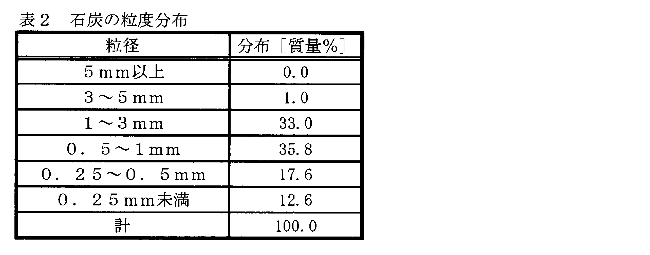
本実施例4は、図4を用いて説明した上記第2の実施形態に対応するものである。本実施例4では、上記表2に示したような粒度分布を有する粗破砕した石炭C301(水分含有量:60%)を、スチームチューブ式の間接加熱型の乾燥器301に600kg/h(水分を除くと240kg/h)で投入し、水分含有量が10%になるまで乾燥させた。得られた乾燥石炭C302を、外熱式ロータリーキルンを用いた乾留器303で600℃に昇温し、乾留を行った。その結果、138kg/hのチャー、69Nm3/hのガス(CO,H2,CH4を主成分とする、熱量3450kcal/Nm3のガス)、及び、19kg/hのタールを得ることができ、得られた全量を燃焼器311に送って燃焼させて1500℃の燃焼ガスとした。燃焼器311では、これらの揮発分に加えて、流動層冷却分級器307から回収した9kg/hの微粉チャーC306を同時に燃焼させた。本実施例4において最終的に製品として回収されたチャーC305の量は、129kg/hとなった。なお、この実施例4においては、図4に示した配管L301を利用して、燃焼ガスG303の冷却を行っている。
本実施例5は、図7を用いて説明した上記第3の実施形態に対応するものである。本実施例5では、上記表2に示したような粒度分布を有する粗破砕した石炭C301(水分含有量:60%)を、流動層乾燥分級器351に600kg/h(水分を除くと240kg/h)で投入し、流動層乾燥分級器351において350℃かつ2600Nm3/hの加熱ガスG301を用いて、水分含有量が10%になるまで乾燥させた。得られた乾燥石炭C302を、外熱式ロータリーキルンを用いた乾留器303で600℃に昇温し、乾留を行った。その結果、135kg/hのチャーC305、68Nm3/hのガス(CO,H2,CH4を主成分とする、熱量3450kcal/Nm3のガス)、及び、19kg/hのタールを得ることができ、得られた全量を燃焼器311に送って1500℃の燃焼ガスG303を得た。燃焼器311では、これらの揮発分に加えて、流動層乾燥分級器351から回収した10kg/hの乾燥微粉炭C303、及び、流動層冷却分級器307から回収した5kg/hの微粉チャーC306を同時に燃焼させた。本実施例5において最終的に製品として回収されたチャーC305の量は、130kg/hとなった。なお、この実施例5においては、図7に示した配管L301を利用して、燃焼ガスG303を冷却している。操業後に乾留器303から燃焼器311への配管内部を検査したところ、ダスト付着は殆ど生じておらず、キャリーオーバーは殆ど生じていなかった。
本実施例6も、図7を用いて説明した上記第3の実施形態に対応するものである。本実施例6では、上記表2に示したような粒度分布を有する粗破砕した石炭C301(水分含有量:58%)を、流動層乾燥分級器351に571kg/h(水分を除くと240kg/h)で投入し、流動層乾燥分級器351において320℃でかつ2600Nm3/hの加熱ガスG301を用いて、水分含有量が10%になるまで乾燥させた。得られた乾燥石炭C302を、外熱式ロータリーキルンを用いた乾留器303で600℃に昇温し、乾留を行った。その結果、135kg/hのチャー、68Nm3/hのガス(CO,H2,CH4を主成分とする、熱量3450kcal/Nm3のガス)、及び、19kg/hのタールを得ることができ、得られた全量を燃焼器311に送って1500℃の燃焼ガスG303を得た。燃焼器311では、これらの揮発分に加えて、流動層乾燥分級器351から回収した7kg/hの乾燥微粉炭C303、及び、流動層冷却分級器307から回収した2kg/hの微粉チャーC306を同時に燃焼させた。本実施例6において最終的に製品として回収されたチャーC305の量は133kg/hとなり、チャーの回収量(回収率)が向上した。なお、この実施例6においては、図7に示したL304のラインを用いて流動層乾燥分級器351で回収した15kgの微粉炭C303のうちの8kgを、成型機(図示せず)を用いて圧縮成型した後に乾留器302に投入するとともに、図7に示した配管L301を利用して、燃焼ガスG303の冷却を行っている。操業後に乾留器303から燃焼器311への配管内部を検査したところ、ダスト付着は殆ど生じておらず、キャリーオーバーは殆ど生じていなかった。
図示されない従来の装置を用いて従来の方法で石炭改質を行った比較例2を以下に示す。
まず、上記表2に示したような粒度分布を有する粗破砕した石炭(水分含有量:60%)を、バンド乾燥器に600kg/hで投入し、バンド乾燥器において330℃のガス2700Nm3/hを用いて、水分含有量が10%になるまで乾燥させた。得られた乾燥石炭を、外熱式ロータリーキルンを用いた乾留器で600℃に昇温し、乾留を行った。その結果、139kg/hのチャー、69Nm3/hのガス(CO,H2,CH4を主成分とする、熱量3450kcal/Nm3のガス)、及び、19kg/hのタールを得ることができ、得られた全量を燃焼器に送って燃焼させて1500℃の燃焼ガスを得た。その結果、乾燥器及び乾留器で求められる熱量を賄うことが出来なかったため、燃焼器に16kg/hの重油を供給して燃焼させ、処理に求められる熱量を確保した。このように、流動層冷却分級器からの微粉チャーを用いない場合には、16kg/hの重油が必要となった。操業後に乾留器から燃焼器への配管内部を検査したところ、ダスト付着が生じており(特に曲げ部において顕著であった)、キャリーオーバーが生じていることが判った。従って、長時間の操業では、配管詰まりの発生が懸念される。
(15)この石炭改質方法は、石炭C301を乾燥器301で乾燥させる工程と;乾燥石炭C302を乾留器303で乾留して、乾留ガスD301及びチャーC304に改質する工程と;チャーC304を流動層冷却分級器307で冷却しながら分級して微粉チャーC306を分離する工程と;微粉チャーC306と乾留ガスD301の少なくとも一部とを燃焼器311へと供給して燃焼させて得た熱を、乾燥器301及び乾留器303の少なくとも何れか一方に熱源として供給する工程と;を備える。
(16)上記(15)に記載の石炭改質方法は、乾燥器301及び流動層冷却分級器307の少なくとも何れか一方から排出される排ガスを冷却ガスとして流動層冷却分級器307に供給する工程を更に備えてもよい。
(17)上記(15)又は(16)に記載の石炭改質方法は、乾燥器301から排出される排ガスG302の少なくとも一部を、燃焼器311から、乾燥器301及び乾留器303の少なくとも何れか一方へと供給される燃焼ガスG303に混合する工程をさらに備えてもよい。
(18)上記(15)~(17)の何れか1項に記載の石炭改質方法では、乾留器303が、外部から加熱ガスの供給を受ける間接加熱方式であり;乾留器303から排出された後の加熱ガスG301を、乾燥器301へと供給する工程をさらに備える;ようにしてもよい。
(19)上記(15)~(18)の何れか1項に記載の石炭改質方法では、石炭C301を乾燥器で乾燥させる工程で、乾燥器として流動層乾燥分級器351を用いることで、石炭C301を乾燥させながら乾燥石炭C302である粗粒炭と微粉炭C303とに分級し;微粉炭C303を燃焼器311へと供給する工程をさらに備える;ようにしてもよい。
(20)上記(19)に記載の石炭改質方法は、流動層乾燥分級器351から排出される排ガスG302の少なくとも一部を、流動層乾燥分級器351に前記熱源として供給される加熱ガスG303に混合する工程をさらに備えてもよい。
(21)上記(19)又は(20)に記載の石炭改質方法は、流動層乾燥分級器351から得られる微粉炭C303の少なくとも一部を、乾留器303へと供給する工程をさらに備えてもよい。
(22)上記(21)に記載の石炭改質方法では、流動層乾燥分級器351から得られる微粉炭C303の少なくとも一部を、単独で成形、又は乾燥石炭C302と共に成形した後に、乾留器303へと供給してもよい。
(23)上記(15)~(22)の何れか1項に記載の石炭改質方法では、燃焼器311に供給する微粉チャーC306及び乾留ガスD301のうちの乾留ガスD301の代わりに、外部燃料を用いてもよい。
(24)石炭改質装置310は、石炭C301を乾燥させる乾燥器301と;乾燥石炭C302を乾留して、乾留ガスD301及びチャーC304に改質する乾留器303と;チャーC304を冷却しながら分級してチャーC304より微粉チャーC306を分離する流動層冷却分級器307と;微粉チャーC306と、乾留ガスD301の少なくとも一部と、が供給され、乾留ガスD301及び微粉チャーC304を燃焼させることで得られる熱を、乾燥器301又は乾留器303の少なくとも何れか一方に熱源として供給する燃焼器311と;を備える。
(25)上記(24)に記載の石炭改質装置310では、乾燥器301又は流動層冷却分級器307の少なくとも何れか一方から排出される排ガスが、冷却ガスとして流動層冷却分級器307に供給されるようにしてもよい。
(26)上記(24)又は(25)に記載の石炭改質装置310では、乾燥器301から排出される排ガスG302の少なくとも一部が、燃焼器311から乾燥器301及び乾留器303の少なくとも何れか一方に前記熱源として供給される燃焼ガスG303に混合されるように構成してもよい。
(27)上記(24)~(26)の何れか1項に記載の石炭改質装置310では、乾留器303が、外部からの加熱ガスの供給を受ける間接加熱方式であり;乾留器303から排出された加熱ガスG301が、乾燥器301へと供給される;構成を採用してもよい。
(28)上記(24)~(27)の何れか1項に記載の石炭改質装置310の他の態様である石炭改質装置410では、前記乾燥器が、石炭C301を乾燥させながら乾燥石炭C302である粗粒炭と微粉炭C303とに分級する流動層乾燥分級器351であり;微粉炭C303が燃焼器311へと供給される;構成を採用してもよい。
(29)上記(28)に記載の石炭改質装置410では、流動層乾燥分級器351から排出される排ガスG302の少なくとも一部が、流動層乾燥分級器351に前記熱源として供給される加熱ガスG301に混合されるように構成してもよい。
(30)上記(28)又は(29)に記載の石炭改質装置410では、流動層乾燥分級器351から得られる微粉炭C303の少なくとも一部が、乾留器303へと供給される構成を採用してもよい。
(31)上記(30)に記載の石炭改質装置410では、微粉炭C303を単独で成形、又は乾燥石炭C302と共に成形する成形機を更に備え;流動層乾燥分級器351から得られる微粉炭C303の少なくとも一部が、前記成形機により、単独で成形、又は前記乾燥石炭C302と共に成形された後に、乾留器303へと供給される;構成を採用してもよい。
(32)上記(24)~(31)の何れか1項に記載の石炭改質装置では、燃焼器311に供給する微粉チャーC306及び乾留ガスD301のうちの乾留ガスD301の代わりに、外部燃料を用いてもよい。
本発明の石炭改質方法及び石炭改質装置は、追加の外部燃料を用いることなく石炭改質プロセスを行えることにも特徴があり、その結果として、製造効率の向上を実現している。以下、この点を確認するために、実施例7~9と比較例3とを示す。
本実施例7は、図1を用いて説明した上記第1の実施形態に対応する。
本実施例7では、前述の表1に示した粒度分布を有する粗破砕した石炭C1(水分含有量:60%)を、流動層乾燥分級器101に560kg/h(水分を除くと240kg/h)で投入し、流動層乾燥分級器101において230℃でかつ2800Nm3/hの加熱ガスG1を用いて、水分含有量が10%になるまで乾燥させた。
燃焼器109では、流動層乾燥分級器101から回収した15kg/hのうちの6kg/hの乾燥微粉炭C3を同時に燃焼させた。残りの9kg/hの乾燥微粉炭C3は、図1中の配管L3上に設けられた成型機(図中表示なし)で圧縮成型を行ってから乾留器103へ投入した。
その結果、チャーの回収量(回収率)が向上すると共に、回収されたチャー中の微粉も後述の比較例3に比べて少なく、発塵の少ないチャーであることが確認された。なお、この実施例7においては、図1に示した配管L1を利用して集塵器105からの排ガスを混合させることで、加熱ガスG1の冷却を行った。
本実施例8は、図4を用いて説明した上記第2の実施形態に対応するものである。
本実施例8では、前述の表2に示したような粒度分布を有する粗破砕した石炭C301(水分含有量:60%)を、スチームチューブ式の間接加熱型の乾燥器301に600kg/h(水分を除くと240kg/h)で投入し、水分含有量が10%になるまで乾燥させた。
燃焼器311では、これらの揮発分に加えて、流動層冷却分級器307から回収した3kg/hの微粉チャーC306を同時に燃焼させた。本実施例8において最終的に製品として回収されたチャーC305の量は、129kg/hとなった。なお、この実施例8においては、図4に示した配管L301を利用して、排ガスの一部を混合することで燃焼ガスG303の冷却を行っている。
本実施例9は、図7を用いて説明した上記第3の実施形態に対応するものである。
本実施例9では、前述の表2に示した粒度分布を有する粗破砕した石炭C301(水分含有量:60%)を、流動層乾燥分級器351に560kg/h(水分を除くと240kg/h)で投入し、流動層乾燥分級器351において230℃でかつ2800Nm3/hの加熱ガスG301を用いて、水分含有量が10%になるまで乾燥させた。
前述の表1に示した粒度分布を有する粗破砕した石炭(水分含有量:60%)をスチームチューブ式乾燥器に600kg/hで投入し、水分含有量が10%になるまで乾燥させた。
得られた乾燥石炭を、外熱式ロータリーキルンである乾留器で600℃に昇温させ、乾留を行った。その結果、139kg/hのチャー、69Nm3/hのガス(CO,H2,CH4を主成分とする、熱量3450kcal/Nm3のガス)、及び、19kg/hのタールを得ることができ、得られたガスとタールの全量および飛散したチャー7kg/hを燃焼器において燃焼させ、1500℃の燃焼ガスとした。
操業後に乾留器から燃焼器への配管内部を検査したところ、ダスト付着が生じており(特に曲げ部において顕著であった)、キャリーオーバーが生じていることが判った。さらに燃焼器出口ガスをサンプリングしたところ、未反応の固体粒子が測定された。従って、長時間の操業では、配管詰まりの発生が懸念される。
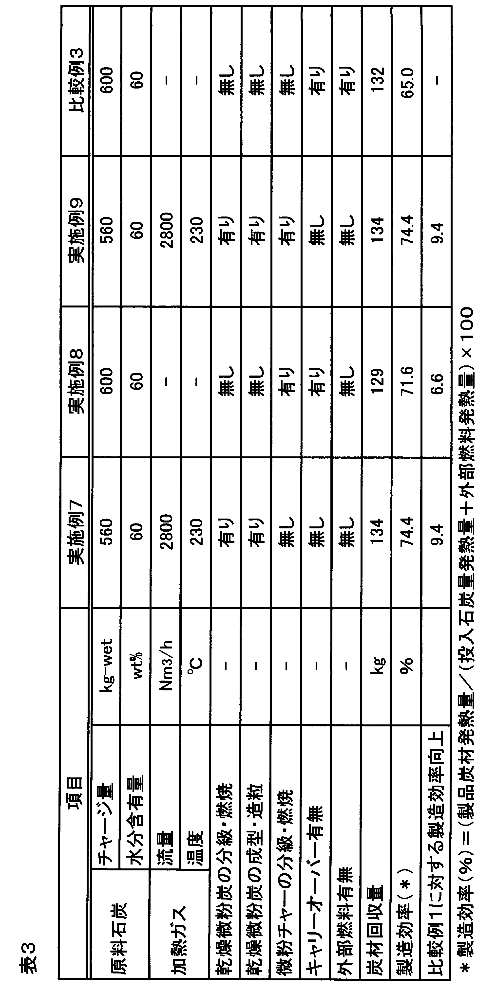
101,351 流動層乾燥分級器
103,303 乾留器
105,309,353 集塵器
107 冷却器
109,311 燃焼器
301 乾燥器
305 ボイラー
307 流動層冷却分級器
Claims (32)
- 石炭を流動層乾燥分級器で乾燥させながら粗粒炭及び微粉炭に分級する工程と;
前記粗粒炭を乾留器によって乾留して、乾留ガスとチャーとに改質する工程と;
前記微粉炭の少なくとも一部と前記乾留ガスの少なくとも一部とを燃焼器に供給して燃焼させて得た熱を、前記流動層乾燥分級器及び前記乾留器の少なくとも何れか一方に熱源として供給する工程と;
を備えることを特徴とする、石炭改質方法。 - 前記流動層乾燥分級器から排出される排ガスの少なくとも一部を、前記燃焼器から前記流動層乾燥分級器及び前記乾留器の少なくとも何れか一方へと供給される燃焼ガスに混合する工程
をさらに備えることを特徴とする、請求項1に記載の石炭改質方法。 - 前記流動層乾燥分級器で得られる前記微粉炭の少なくとも一部を、前記乾留器へと供給する工程
をさらに備えることを特徴とする、請求項1に記載の石炭改質方法。 - 前記乾留器に供給される前記微粉炭を、単独で成形した後、又は前記粗粒炭と共に成形した後に、前記乾留器へと供給する
ことを特徴とする、請求項3に記載の石炭改質方法。 - 前記乾留器が、外部からの加熱ガスの供給を受ける間接加熱方式であり;
前記乾留器から排出された後の前記加熱ガスを、前記流動層乾燥分級器へと供給する工程をさらに備える;
ことを特徴とする、請求項1に記載の石炭改質方法。 - 前記流動層乾燥分級器から排出される排ガスの少なくとも一部を、前記流動層乾燥分級器に供給される加熱ガスに混合する工程をさらに備える
ことを特徴とする、請求項1に記載の石炭改質方法。 - 前記燃焼器に供給する前記微粉炭及び前記乾留ガスのうちの前記乾留ガスの代わりに、外部燃料を用いる
ことを特徴とする、請求項1に記載の石炭改質方法。 - 石炭を乾燥させながら粗粒炭と微粉炭とに分級する流動層乾燥分級器と;
乾燥後の前記粗粒炭を乾留して、乾留ガス及びチャーに改質する乾留器と;
前記乾留ガスの少なくとも一部と前記微粉炭とが供給され、前記乾留ガス及び前記微粉炭を燃焼させることで得られる熱を、前記流動層乾燥分級器及び前記乾留器の少なくとも何れか一方に熱源として供給する燃焼器と;
を備えることを特徴とする、石炭改質装置。 - 前記流動層乾燥分級器から排出される排ガスの少なくとも一部が、前記燃焼器から、前記流動層乾燥分級器及び前記乾留器の少なくとも何れか一方に前記熱源として供給される燃焼ガスに混合される
ことを特徴とする、請求項8に記載の石炭改質装置。 - 前記流動層乾燥分級器で得られる前記微粉炭の少なくとも一部が、前記乾留器へと供給される
ことを特徴とする、請求項8に記載の石炭改質装置。 - 前記微粉炭を単独で成形、又は前記粗粒炭と共に成形する成形機を更に備え;
前記流動層乾燥分級器から得られる前記微粉炭の少なくとも一部が、前記成形機により単独で成形された後、又は前記粗粒炭と共に成形された後に、前記乾留器へと供給される;
ことを特徴とする、請求項10に記載の石炭改質装置。 - 前記乾留器が、外部から加熱ガスの供給を受ける間接加熱方式であり;
前記乾留器から排出された後の前記加熱ガスが、前記流動層乾燥分級器へと供給される;
ことを特徴とする、請求項8に記載の石炭改質装置。 - 前記流動層乾燥分級器から排出される排ガスの少なくとも一部が、前記流動層乾燥分級器に前記熱源として供給される加熱ガスに混合される
ことを特徴とする、請求項8に記載の石炭改質装置。 - 前記燃焼器に供給する前記微粉炭及び前記乾留ガスのうちの前記乾留ガスの代わりに、外部燃料を用いる
ことを特徴とする、請求項8に記載の石炭改質装置。 - 石炭を乾燥器で乾燥させる工程と;
乾燥後の前記石炭を乾留器で乾留して、乾留ガス及びチャーに改質する工程と;
前記チャーを流動層冷却分級器で冷却しながら分級して微粉チャーを分離する工程と;
前記微粉チャーと前記乾留ガスの少なくとも一部とを燃焼器へと供給して燃焼させて得た熱を、前記乾燥器及び前記乾留器の少なくとも何れか一方に熱源として供給する工程と;
を備えることを特徴とする、石炭改質方法。 - 前記乾燥器及び前記流動層冷却分級器の少なくとも何れか一方から排出される排ガスを冷却ガスとして前記流動層冷却分級器に供給する工程
を更に備えることを特徴とする、請求項15に記載の石炭改質方法。 - 前記乾燥器から排出される排ガスの少なくとも一部を、前記燃焼器から、前記乾燥器及び前記乾留器の少なくとも何れか一方へと供給される燃焼ガスに混合する工程をさらに備える
ことを特徴とする、請求項15に記載の石炭改質方法。 - 前記乾留器が、外部から加熱ガスの供給を受ける間接加熱方式であり;
前記乾留器から排出された後の前記加熱ガスを、前記乾燥器へと供給する工程をさらに備える;
ことを特徴とする、請求項15に記載の石炭改質方法。 - 前記石炭を前記乾燥器で乾燥させる工程で、前記乾燥器として流動層乾燥分級器を用いることで、前記石炭を乾燥させながら粗粒炭と微粉炭とに分級し;
前記微粉炭を前記燃焼器へと供給する工程をさらに備える;
ことを特徴とする、請求項15に記載の石炭改質方法。 - 前記流動層乾燥分級器から排出される排ガスの少なくとも一部を、前記流動層乾燥分級器に前記熱源として供給される加熱ガスに混合する工程をさらに備える
ことを特徴とする、請求項19に記載の石炭改質方法。 - 前記流動層乾燥分級器から得られる前記微粉炭の少なくとも一部を、前記乾留器へと供給する工程をさらに備える
ことを特徴とする、請求項19に記載の石炭改質方法。 - 前記流動層乾燥分級器から得られる前記微粉炭の少なくとも一部を、単独で成形又は前記粗粒炭と共に成形した後に、前記乾留器へと供給する
ことを特徴とする、請求項21に記載の石炭改質方法。 - 前記燃焼器に供給する前記微粉チャー及び前記乾留ガスのうちの前記乾留ガスの代わりに、外部燃料を用いる
ことを特徴とする、請求項15に記載の石炭改質方法。 - 石炭を乾燥させる乾燥器と;
乾燥後の前記石炭を乾留して、乾留ガス及びチャーに改質する乾留器と;
前記チャーを冷却しながら分級して前記チャーより微粉チャーを分離する流動層冷却分級器と;
前記微粉チャーと、前記乾留ガスの少なくとも一部と、が供給され、前記乾留ガス及び前記微粉チャーを燃焼させることで得られる熱を、前記乾燥器又は前記乾留器の少なくとも何れか一方に熱源として供給する燃焼器と;
を備える
ことを特徴とする、石炭改質装置。 - 前記乾燥器又は前記流動層冷却分級器の少なくとも何れか一方から排出される排ガスが、冷却ガスとして前記流動層冷却分級器に供給される
ことを特徴とする、請求項24に記載の石炭改質装置。 - 前記乾燥器から排出される排ガスの少なくとも一部が、前記燃焼器から前記乾燥器及び前記乾留器の少なくとも何れか一方に前記熱源として供給される燃焼ガスに混合される
ことを特徴とする、請求項24に記載の石炭改質装置。 - 前記乾留器が、外部からの加熱ガスの供給を受ける間接加熱方式であり;
前記乾留器から排出された前記加熱ガスが、前記乾燥器へと供給される;
ことを特徴とする、請求項24に記載の石炭改質装置。 - 前記乾燥器は、前記石炭を乾燥させながら粗粒炭と微粉炭とに分級する流動層乾燥分級器であり;
前記微粉炭が前記燃焼器へと供給される;
ことを特徴とする、請求項24に記載の石炭改質装置。 - 前記流動層乾燥分級器から排出される排ガスの少なくとも一部が、前記流動層乾燥分級器に前記熱源として供給される加熱ガスに混合される;
ことを特徴とする、請求項28に記載の石炭改質装置。 - 前記流動層乾燥分級器から得られる前記微粉炭の少なくとも一部が、前記乾留器へと供給される
ことを特徴とする、請求項28に記載の石炭改質装置。 - 前記微粉炭を単独で成形、又は前記粗粒炭と共に成形する成形機を更に備え;
前記流動層乾燥分級器から得られる前記微粉炭の少なくとも一部が、前記成形機により、単独で成形、又は前記粗粒炭と共に成形された後に、前記乾留器へと供給される;
ことを特徴とする、請求項30に記載の石炭改質装置。 - 前記燃焼器に供給する前記微粉チャー及び前記乾留ガスのうちの前記乾留ガスの代わりに、外部燃料を用いる
ことを特徴とする、請求項24に記載の石炭改質装置。
Priority Applications (4)
| Application Number | Priority Date | Filing Date | Title |
|---|---|---|---|
| AU2013291057A AU2013291057B2 (en) | 2012-07-20 | 2013-07-19 | Coal reforming method and coal reforming apparatus |
| CN201380047992.7A CN104662136B (zh) | 2012-07-20 | 2013-07-19 | 煤改性方法和煤改性装置 |
| JP2013556711A JP5597778B2 (ja) | 2012-07-20 | 2013-07-19 | 石炭改質方法及び石炭改質装置 |
| US14/415,107 US9309465B2 (en) | 2012-07-20 | 2013-07-19 | Coal reforming method and coal reforming apparatus |
Applications Claiming Priority (4)
| Application Number | Priority Date | Filing Date | Title |
|---|---|---|---|
| JP2012162080 | 2012-07-20 | ||
| JP2012162081 | 2012-07-20 | ||
| JP2012-162080 | 2012-07-20 | ||
| JP2012-162081 | 2012-07-20 |
Publications (1)
| Publication Number | Publication Date |
|---|---|
| WO2014014092A1 true WO2014014092A1 (ja) | 2014-01-23 |
Family
ID=49948912
Family Applications (1)
| Application Number | Title | Priority Date | Filing Date |
|---|---|---|---|
| PCT/JP2013/069671 Ceased WO2014014092A1 (ja) | 2012-07-20 | 2013-07-19 | 石炭改質方法及び石炭改質装置 |
Country Status (5)
| Country | Link |
|---|---|
| US (1) | US9309465B2 (ja) |
| JP (1) | JP5597778B2 (ja) |
| CN (1) | CN104662136B (ja) |
| AU (1) | AU2013291057B2 (ja) |
| WO (1) | WO2014014092A1 (ja) |
Cited By (5)
| Publication number | Priority date | Publication date | Assignee | Title |
|---|---|---|---|---|
| CN104789244A (zh) * | 2015-04-13 | 2015-07-22 | 陕西煤业化工集团神木天元化工有限公司 | 一种带煤气循环的回转炉粉煤热解生产无烟煤方法 |
| CN105112079A (zh) * | 2015-09-17 | 2015-12-02 | 湖南华银能源技术有限公司 | 一种无废水排放的煤提质方法 |
| JP2019502785A (ja) * | 2015-12-10 | 2019-01-31 | ポスコPosco | 炭材の改質方法及びその装置 |
| CN110423628A (zh) * | 2019-09-09 | 2019-11-08 | 重庆润科新材料技术有限公司 | 一种低阶煤干馏生产装置及方法 |
| CN113420461A (zh) * | 2021-07-20 | 2021-09-21 | 山东恒拓科技发展有限公司 | 水泥分解炉在线仿真系统及其建立方法 |
Families Citing this family (15)
| Publication number | Priority date | Publication date | Assignee | Title |
|---|---|---|---|---|
| JP5597778B2 (ja) | 2012-07-20 | 2014-10-01 | 新日鐵住金株式会社 | 石炭改質方法及び石炭改質装置 |
| CN106118697A (zh) * | 2016-08-12 | 2016-11-16 | 田东昊润新材料科技有限公司 | 热能循环利用的褐煤连续式焦化设备 |
| CN106590709B (zh) * | 2016-10-27 | 2019-06-18 | 武汉钢铁有限公司 | 基于水煤气制备并循环的干熄焦工艺 |
| CN106479543B (zh) * | 2016-10-27 | 2019-11-05 | 武汉钢铁有限公司 | 基于干熄冷焦破碎去湿的炼焦煤预处理工艺 |
| KR101891197B1 (ko) * | 2017-04-11 | 2018-08-23 | 주식회사 포스코 | 원료 저장 장치 및 그 저장방법 |
| CN107099315B (zh) * | 2017-05-27 | 2020-04-28 | 中信重工机械股份有限公司 | 低阶煤热解过程中水蒸汽与荒煤气的分离方法 |
| JP6419375B1 (ja) * | 2018-05-16 | 2018-11-07 | 新日鉄住金エンジニアリング株式会社 | 乾燥装置及び乾燥方法 |
| KR102014452B1 (ko) * | 2019-03-15 | 2019-08-26 | 장철 | 석탄 고품위화 시스템 |
| CN110564437B (zh) * | 2019-09-18 | 2021-02-09 | 中国科学院山西煤炭化学研究所 | 一种煤粉炉炉前煤提质系统及方法 |
| WO2022141624A1 (zh) * | 2021-01-04 | 2022-07-07 | 山东省科学院能源研究所 | 一种连续式固体有机物热解多联产系统及其使用方法 |
| US11268039B1 (en) * | 2021-06-28 | 2022-03-08 | Aries Clean Technologies Llc | Direct biochar cooling methods and systems |
| US11268030B1 (en) * | 2021-06-28 | 2022-03-08 | Aries Clean Technologies Llc | Direct biochar cooling methods and systems |
| US11268031B1 (en) * | 2021-06-28 | 2022-03-08 | Aries Clean Technologies Llc | Direct biochar cooling methods and systems |
| US11414322B1 (en) | 2021-02-24 | 2022-08-16 | Aries Clean Technologies Llc | Methods and systems for producing an enhanced surface area biochar product |
| US11268029B1 (en) * | 2021-06-28 | 2022-03-08 | Aries Clean Technologies Llc | Direct biochar cooling methods and systems |
Citations (5)
| Publication number | Priority date | Publication date | Assignee | Title |
|---|---|---|---|---|
| JPH0565487A (ja) * | 1991-09-10 | 1993-03-19 | Nippon Steel Corp | コークス炉の原料炭装入方法 |
| JPH10287882A (ja) * | 1997-04-11 | 1998-10-27 | Nippon Steel Chem Co Ltd | コークス製造用原料炭の事前処理方法及びコークスの製造法 |
| JPH11181443A (ja) * | 1997-12-19 | 1999-07-06 | Mitsubishi Chemical Corp | コークス製造のための原料炭の事前処理方法 |
| JP2005036078A (ja) * | 2003-07-18 | 2005-02-10 | Nippon Steel Corp | コークス乾式消火設備におけるコークス粉の処理方法及び処理装置 |
| JP2008138021A (ja) * | 2006-11-30 | 2008-06-19 | Nippon Steel Corp | コークス炉の石炭事前処理方法及び装置 |
Family Cites Families (11)
| Publication number | Priority date | Publication date | Assignee | Title |
|---|---|---|---|---|
| US3384557A (en) * | 1964-07-21 | 1968-05-21 | Fmc Corp | Method of curing of green briquettes by oxidation |
| US3574065A (en) * | 1969-08-05 | 1971-04-06 | Fmc Corp | Fractional carbonization of coal |
| US4002533A (en) | 1972-07-06 | 1977-01-11 | Westvaco Corporation | Two-step process for conditioning sized coal and resulting product |
| JPS61136586A (ja) * | 1984-12-05 | 1986-06-24 | Nippon Steel Corp | 石炭の間接加熱たて型連続乾留炉 |
| US6453830B1 (en) * | 2000-02-29 | 2002-09-24 | Bert Zauderer | Reduction of nitrogen oxides by staged combustion in combustors, furnaces and boilers |
| JP2003183670A (ja) * | 2001-12-19 | 2003-07-03 | Nippon Steel Corp | 石炭の事前処理方法 |
| JP5148809B2 (ja) | 2004-05-07 | 2013-02-20 | 三菱重工環境・化学エンジニアリング株式会社 | 汚泥の燃料化方法及び装置 |
| US7987613B2 (en) * | 2004-10-12 | 2011-08-02 | Great River Energy | Control system for particulate material drying apparatus and process |
| CN101760222B (zh) | 2009-12-25 | 2011-05-04 | 山东天力干燥设备有限公司 | 一种新型流化床半焦生产系统及其工艺 |
| CN102465043B (zh) * | 2010-11-01 | 2013-07-31 | 中国科学院过程工程研究所 | 一种固体燃料的多段分级热解气化装置及方法 |
| JP5597778B2 (ja) | 2012-07-20 | 2014-10-01 | 新日鐵住金株式会社 | 石炭改質方法及び石炭改質装置 |
-
2013
- 2013-07-19 JP JP2013556711A patent/JP5597778B2/ja not_active Expired - Fee Related
- 2013-07-19 CN CN201380047992.7A patent/CN104662136B/zh active Active
- 2013-07-19 US US14/415,107 patent/US9309465B2/en active Active
- 2013-07-19 WO PCT/JP2013/069671 patent/WO2014014092A1/ja not_active Ceased
- 2013-07-19 AU AU2013291057A patent/AU2013291057B2/en active Active
Patent Citations (5)
| Publication number | Priority date | Publication date | Assignee | Title |
|---|---|---|---|---|
| JPH0565487A (ja) * | 1991-09-10 | 1993-03-19 | Nippon Steel Corp | コークス炉の原料炭装入方法 |
| JPH10287882A (ja) * | 1997-04-11 | 1998-10-27 | Nippon Steel Chem Co Ltd | コークス製造用原料炭の事前処理方法及びコークスの製造法 |
| JPH11181443A (ja) * | 1997-12-19 | 1999-07-06 | Mitsubishi Chemical Corp | コークス製造のための原料炭の事前処理方法 |
| JP2005036078A (ja) * | 2003-07-18 | 2005-02-10 | Nippon Steel Corp | コークス乾式消火設備におけるコークス粉の処理方法及び処理装置 |
| JP2008138021A (ja) * | 2006-11-30 | 2008-06-19 | Nippon Steel Corp | コークス炉の石炭事前処理方法及び装置 |
Cited By (5)
| Publication number | Priority date | Publication date | Assignee | Title |
|---|---|---|---|---|
| CN104789244A (zh) * | 2015-04-13 | 2015-07-22 | 陕西煤业化工集团神木天元化工有限公司 | 一种带煤气循环的回转炉粉煤热解生产无烟煤方法 |
| CN105112079A (zh) * | 2015-09-17 | 2015-12-02 | 湖南华银能源技术有限公司 | 一种无废水排放的煤提质方法 |
| JP2019502785A (ja) * | 2015-12-10 | 2019-01-31 | ポスコPosco | 炭材の改質方法及びその装置 |
| CN110423628A (zh) * | 2019-09-09 | 2019-11-08 | 重庆润科新材料技术有限公司 | 一种低阶煤干馏生产装置及方法 |
| CN113420461A (zh) * | 2021-07-20 | 2021-09-21 | 山东恒拓科技发展有限公司 | 水泥分解炉在线仿真系统及其建立方法 |
Also Published As
| Publication number | Publication date |
|---|---|
| US20150175891A1 (en) | 2015-06-25 |
| AU2013291057B2 (en) | 2015-06-18 |
| JP5597778B2 (ja) | 2014-10-01 |
| CN104662136A (zh) | 2015-05-27 |
| CN104662136B (zh) | 2016-08-17 |
| JPWO2014014092A1 (ja) | 2016-07-07 |
| US9309465B2 (en) | 2016-04-12 |
| AU2013291057A1 (en) | 2015-02-12 |
Similar Documents
| Publication | Publication Date | Title |
|---|---|---|
| JP5597778B2 (ja) | 石炭改質方法及び石炭改質装置 | |
| KR101643792B1 (ko) | 2단계 건조 공급 기화 시스템 및 공정 | |
| CN104169395B (zh) | 用于控制含碳物质的快速热处理的热量的装置和方法 | |
| JP6424182B2 (ja) | コークス用石炭乾燥装置および乾燥方法 | |
| CN103045275B (zh) | 一种自热式热解方法 | |
| US12270002B2 (en) | Process of treating carbonaceous material and apparatus therefor | |
| CN101896581B (zh) | 生产焦炭和燃料气的方法和装置 | |
| JP5407496B2 (ja) | 流動床乾燥加熱分級装置及びコークス炉用原料炭の事前処理方法 | |
| AU2018282459B2 (en) | Dry-distilled coal cooling device, coal upgrading plant, and dry-distilled coal cooling method | |
| US20090217574A1 (en) | Process, system and apparatus for passivating carbonaceous materials | |
| JP5929489B2 (ja) | アブラ椰子核殻炭の製造方法 | |
| JP2011144330A (ja) | 木質バイオマスのガス化システム及びその方法 | |
| US10188980B2 (en) | Coal upgrade plant and method for manufacturing upgraded coal | |
| CN108148610B (zh) | 一种用于炼焦原料煤的预处理方法 | |
| CN103695013B (zh) | 含碳固体燃料热解的系统及方法 | |
| JPH10287882A (ja) | コークス製造用原料炭の事前処理方法及びコークスの製造法 | |
| JP6741393B2 (ja) | 流動床装置及びこれを用いた石炭の乾燥分級方法 | |
| CN102822317B (zh) | 烧结用固体燃料的制造方法、烧结用固体燃料及采用其的烧结矿的制造方法 | |
| JP5714142B2 (ja) | 石炭乾留装置 | |
| KR20180056210A (ko) | 원료 처리 방법 | |
| JPS5829997B2 (ja) | 都市固形廃棄物の流動熱分解法 | |
| WO2021200520A1 (ja) | 炭化物の製造方法および炭化物の製造設備 |
Legal Events
| Date | Code | Title | Description |
|---|---|---|---|
| ENP | Entry into the national phase |
Ref document number: 2013556711 Country of ref document: JP Kind code of ref document: A |
|
| 121 | Ep: the epo has been informed by wipo that ep was designated in this application |
Ref document number: 13819759 Country of ref document: EP Kind code of ref document: A1 |
|
| WWE | Wipo information: entry into national phase |
Ref document number: 14415107 Country of ref document: US |
|
| NENP | Non-entry into the national phase |
Ref country code: DE |
|
| WWE | Wipo information: entry into national phase |
Ref document number: IDP00201500593 Country of ref document: ID |
|
| ENP | Entry into the national phase |
Ref document number: 2013291057 Country of ref document: AU Date of ref document: 20130719 Kind code of ref document: A |
|
| 122 | Ep: pct application non-entry in european phase |
Ref document number: 13819759 Country of ref document: EP Kind code of ref document: A1 |