WO2014013683A1 - 加熱装置 - Google Patents
加熱装置 Download PDFInfo
- Publication number
- WO2014013683A1 WO2014013683A1 PCT/JP2013/004100 JP2013004100W WO2014013683A1 WO 2014013683 A1 WO2014013683 A1 WO 2014013683A1 JP 2013004100 W JP2013004100 W JP 2013004100W WO 2014013683 A1 WO2014013683 A1 WO 2014013683A1
- Authority
- WO
- WIPO (PCT)
- Prior art keywords
- gasket
- flow path
- housing
- heat medium
- heating
- Prior art date
- Legal status (The legal status is an assumption and is not a legal conclusion. Google has not performed a legal analysis and makes no representation as to the accuracy of the status listed.)
- Ceased
Links
Images






Classifications
-
- F—MECHANICAL ENGINEERING; LIGHTING; HEATING; WEAPONS; BLASTING
- F24—HEATING; RANGES; VENTILATING
- F24H—FLUID HEATERS, e.g. WATER OR AIR HEATERS, HAVING HEAT-GENERATING MEANS, e.g. HEAT PUMPS, IN GENERAL
- F24H1/00—Water heaters, e.g. boilers, continuous-flow heaters or water-storage heaters
- F24H1/10—Continuous-flow heaters, i.e. heaters in which heat is generated only while the water is flowing, e.g. with direct contact of the water with the heating medium
- F24H1/101—Continuous-flow heaters, i.e. heaters in which heat is generated only while the water is flowing, e.g. with direct contact of the water with the heating medium using electric energy supply
- F24H1/102—Continuous-flow heaters, i.e. heaters in which heat is generated only while the water is flowing, e.g. with direct contact of the water with the heating medium using electric energy supply with resistance
- F24H1/103—Continuous-flow heaters, i.e. heaters in which heat is generated only while the water is flowing, e.g. with direct contact of the water with the heating medium using electric energy supply with resistance with bare resistances in direct contact with the fluid
-
- B—PERFORMING OPERATIONS; TRANSPORTING
- B60—VEHICLES IN GENERAL
- B60H—ARRANGEMENTS OF HEATING, COOLING, VENTILATING OR OTHER AIR-TREATING DEVICES SPECIALLY ADAPTED FOR PASSENGER OR GOODS SPACES OF VEHICLES
- B60H1/00—Heating, cooling or ventilating devices
- B60H1/22—Heating, cooling or ventilating devices the heat source being other than the propulsion plant
- B60H1/2215—Heating, cooling or ventilating devices the heat source being other than the propulsion plant the heat being derived from electric heaters
- B60H1/2221—Heating, cooling or ventilating devices the heat source being other than the propulsion plant the heat being derived from electric heaters arrangements of electric heaters for heating an intermediate liquid
-
- F—MECHANICAL ENGINEERING; LIGHTING; HEATING; WEAPONS; BLASTING
- F24—HEATING; RANGES; VENTILATING
- F24H—FLUID HEATERS, e.g. WATER OR AIR HEATERS, HAVING HEAT-GENERATING MEANS, e.g. HEAT PUMPS, IN GENERAL
- F24H1/00—Water heaters, e.g. boilers, continuous-flow heaters or water-storage heaters
- F24H1/0072—Special adaptations
- F24H1/009—Special adaptations for vehicle systems
-
- F—MECHANICAL ENGINEERING; LIGHTING; HEATING; WEAPONS; BLASTING
- F24—HEATING; RANGES; VENTILATING
- F24H—FLUID HEATERS, e.g. WATER OR AIR HEATERS, HAVING HEAT-GENERATING MEANS, e.g. HEAT PUMPS, IN GENERAL
- F24H1/00—Water heaters, e.g. boilers, continuous-flow heaters or water-storage heaters
- F24H1/10—Continuous-flow heaters, i.e. heaters in which heat is generated only while the water is flowing, e.g. with direct contact of the water with the heating medium
- F24H1/101—Continuous-flow heaters, i.e. heaters in which heat is generated only while the water is flowing, e.g. with direct contact of the water with the heating medium using electric energy supply
- F24H1/102—Continuous-flow heaters, i.e. heaters in which heat is generated only while the water is flowing, e.g. with direct contact of the water with the heating medium using electric energy supply with resistance
-
- F—MECHANICAL ENGINEERING; LIGHTING; HEATING; WEAPONS; BLASTING
- F24—HEATING; RANGES; VENTILATING
- F24H—FLUID HEATERS, e.g. WATER OR AIR HEATERS, HAVING HEAT-GENERATING MEANS, e.g. HEAT PUMPS, IN GENERAL
- F24H9/00—Details
- F24H9/0005—Details for water heaters
- F24H9/001—Guiding means
- F24H9/0015—Guiding means in water channels
-
- F—MECHANICAL ENGINEERING; LIGHTING; HEATING; WEAPONS; BLASTING
- F24—HEATING; RANGES; VENTILATING
- F24H—FLUID HEATERS, e.g. WATER OR AIR HEATERS, HAVING HEAT-GENERATING MEANS, e.g. HEAT PUMPS, IN GENERAL
- F24H9/00—Details
- F24H9/18—Arrangement or mounting of grates or heating means
- F24H9/1809—Arrangement or mounting of grates or heating means for water heaters
- F24H9/1818—Arrangement or mounting of electric heating means
-
- H—ELECTRICITY
- H05—ELECTRIC TECHNIQUES NOT OTHERWISE PROVIDED FOR
- H05B—ELECTRIC HEATING; ELECTRIC LIGHT SOURCES NOT OTHERWISE PROVIDED FOR; CIRCUIT ARRANGEMENTS FOR ELECTRIC LIGHT SOURCES, IN GENERAL
- H05B3/00—Ohmic-resistance heating
- H05B3/02—Details
- H05B3/04—Waterproof or air-tight seals for heaters
-
- H—ELECTRICITY
- H05—ELECTRIC TECHNIQUES NOT OTHERWISE PROVIDED FOR
- H05B—ELECTRIC HEATING; ELECTRIC LIGHT SOURCES NOT OTHERWISE PROVIDED FOR; CIRCUIT ARRANGEMENTS FOR ELECTRIC LIGHT SOURCES, IN GENERAL
- H05B3/00—Ohmic-resistance heating
- H05B3/20—Heating elements having extended surface area substantially in a two-dimensional [2D] plane, e.g. plate-heater
- H05B3/22—Heating elements having extended surface area substantially in a two-dimensional [2D] plane, e.g. plate-heater non-flexible
- H05B3/24—Heating elements having extended surface area substantially in a two-dimensional [2D] plane, e.g. plate-heater non-flexible heating conductor being self-supporting
-
- B—PERFORMING OPERATIONS; TRANSPORTING
- B60—VEHICLES IN GENERAL
- B60H—ARRANGEMENTS OF HEATING, COOLING, VENTILATING OR OTHER AIR-TREATING DEVICES SPECIALLY ADAPTED FOR PASSENGER OR GOODS SPACES OF VEHICLES
- B60H1/00—Heating, cooling or ventilating devices
- B60H1/22—Heating, cooling or ventilating devices the heat source being other than the propulsion plant
- B60H2001/2268—Constructional features
- B60H2001/2271—Heat exchangers, burners, ignition devices
-
- F—MECHANICAL ENGINEERING; LIGHTING; HEATING; WEAPONS; BLASTING
- F24—HEATING; RANGES; VENTILATING
- F24H—FLUID HEATERS, e.g. WATER OR AIR HEATERS, HAVING HEAT-GENERATING MEANS, e.g. HEAT PUMPS, IN GENERAL
- F24H2250/00—Electrical heat generating means
- F24H2250/02—Resistances
-
- H—ELECTRICITY
- H05—ELECTRIC TECHNIQUES NOT OTHERWISE PROVIDED FOR
- H05B—ELECTRIC HEATING; ELECTRIC LIGHT SOURCES NOT OTHERWISE PROVIDED FOR; CIRCUIT ARRANGEMENTS FOR ELECTRIC LIGHT SOURCES, IN GENERAL
- H05B2203/00—Aspects relating to Ohmic resistive heating covered by group H05B3/00
- H05B2203/022—Heaters specially adapted for heating gaseous material
Definitions
- the present invention relates to a heating device that heats a circulating heat medium using a heating element.
- a flow path through which the heat medium flows is formed in the housing, and a heating element is disposed in the flow path to heat the heat medium. Therefore, in order to improve the heating performance, heat exchange between the heating element and the heat medium must be activated.
- Patent Document 1 a partition (guide) is formed on the outer surface of the first casing in which the heating element is accommodated, and the flow of the heat medium in the flow path is swung by this partition, and the first casing is interposed.
- a device has been devised to extend the time for heat exchange between the heating element and the heat medium.
- the heating element is configured in a flat plate shape to increase the heat transfer area, and a plurality of through holes are formed in the flat plate heating element to exchange heat between the heating medium and the heating element while sequentially passing through the through holes.
- JP 2011-143781 A Japanese Patent No. 3633329
- the present invention has been made to solve the conventional technical problem, and allows heat exchange between the heating element and the heat medium effectively without increasing the number of parts.
- An object of the present invention is to provide a heating device that can eliminate an increase in pressure loss.
- a heating device includes a housing in which a flow path through which a heat medium flows is configured, and a heating element that is disposed in the flow path in the housing and heats the heat medium.
- Each of the housings has a first housing portion and a second housing portion which are connected in a state where at least one surface is open and the openings are in contact with each other, and the first housing portions.
- a plate-shaped gasket interposed between the butted portions of the second housing part and sealing between the two housing parts, and at least a part of the gasket is located in the flow path, and heat in the flow path It is characterized by controlling the flow of the medium.
- the heating device of the invention of claim 2 is characterized in that, in the above invention, the gasket has a wall portion located in the flow path and a passage portion opened at the wall portion.
- a heating device according to the above invention, wherein the gasket narrows a flow path at a location where air easily collects in the housing, depending on the opening size and / or shape of the passage portion formed in the wall portion. .
- a heating device according to the above invention, wherein the gasket has a notch portion that is formed to protrude from the upper portion of the passage portion located at the upper portion of the flow path.
- a heating device according to the second to fourth aspects of the present invention, wherein the gasket is a flow in a location where the heat medium is difficult to flow in the housing due to the opening size and / or shape of the passage formed in the wall. It is characterized by widening the road.
- the opening size and / or the shape of the passage portion formed in the wall portion of the gasket in the invention of claims 2 to 5 is the allowable range of the pressure loss of the heat medium in the flow path. It is characterized by being set within.
- the heating device of the invention of claim 7 is characterized in that, in each of the above inventions, the heating element is disposed between the two housing parts, and the heating element penetrates the passage part formed in the wall part of the gasket.
- the heating device is characterized in that, in the first to sixth aspects of the present invention, the heating elements are disposed in the respective housing portions, and the gasket is located between the heating elements.
- the heating device of the invention of claim 9 is characterized in that, in each of the above inventions, the heat medium is an antifreeze liquid circulating in the water circuit for vehicle heating.
- a heating apparatus comprising a casing in which a flow path through which a heat medium flows is formed and a heating element that is disposed in the flow path in the casing and heats the heat medium
- the casing Each of the first housing part and the second housing part connected in a state in which at least one surface is open and the openings are butted against each other, and the butted portions of the first housing part and the second housing part And a plate-shaped gasket that seals between the two housing parts, and at least a part of the gasket is located in the flow path and controls the flow of the heat medium in the flow path.
- the gasket that seals between the first housing part and the second housing part is used to reduce the flow of the heat medium flowing in the housing. Will be able to control.
- the flow of the heat medium can be controlled by using the gasket that seals between the casings, so that the heat exchange between the heating element and the heat medium can be effectively performed while reducing the number of parts and the cost. Can be made to do.
- a gasket as in the invention of claim 2 is provided with a wall portion located in the flow path and a passage portion opening in the wall portion, and formed in the wall portion of the gasket as in the invention of claim 3, for example.
- the upper part of the flow path is a place where it is difficult for the heat medium to flow, and a place where air easily collects. If the flow path in this portion is narrowed to extrude air as described above, the heat medium will be more difficult to flow.
- a notch is formed in the upper part of the passage portion located at the upper part of the flow path. If the portion is formed so as to protrude, the heat medium can easily pass through the upper portion of the flow path, and the number of places where heat exchange with the heating element becomes difficult can be reduced. Furthermore, the notch has the effect of reducing the pressure loss of the heat medium.
- the heat medium is generated in the housing. It is possible to make it easy to flow through a difficult-to-flow location, to uniformize the flow rate of the heat medium, to efficiently heat the heat medium by the heat generator, and to avoid an abnormal temperature rise of the heat generator.
- the opening size and / or shape of the passage portion formed in the wall portion of the gasket is set within the allowable range of the pressure loss of the heat medium in the flow path as in the invention of claim 6, the heat medium Therefore, it is possible to prevent the disadvantage of excessively increasing the pressure loss of the heat medium in the housing for controlling the flow of the heat.
- the heating element when the heating element is disposed between the two casings as in the invention of claim 7, by allowing the heating element to pass through the passage portion formed in the wall portion of the gasket, It becomes possible to control the flow of the heat medium by the gasket without any trouble.
- the gasket may be positioned between the heating elements.
- the heating device of each of the above inventions is provided in a vehicle heating water circuit in which the antifreeze liquid circulates as in the invention of claim 9 and is used as an auxiliary heat source or an alternative heat source of the engine by heating the antifreeze liquid as a heat medium, It is possible to improve the air conditioning performance of an air conditioner provided with a cooling water circuit and a vehicle on which the cooling water circuit is mounted, and to reduce costs.
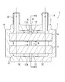
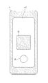
- FIG. 2 is a sectional view taken along line AA in FIG. 1.
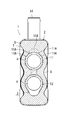
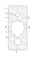
- FIG. 3 is a sectional view taken along line BB in FIG. It is a side view of the 1st housing
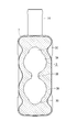
- FIG. 5 is a front view of the gasket of the heating apparatus of FIG.
- the gasket of FIG. 5 correspond to the end surface of the 2nd housing
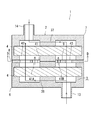
- the heating device 1 includes a housing 2 in which a flow path 3 of a heat medium is formed, and two electric power sources as heating elements provided in the flow path 3 in the housing 2. It consists of a hot wire heater 4.
- the heating device 1 is mounted on a vehicle such as a hybrid vehicle or an electric vehicle.
- a vehicle such as a hybrid vehicle or an electric vehicle.
- an electric source is used as a heat source that supplies heat so as to compensate for waste heat that the engine (heat source) is insufficient.
- heat source heat source
- an automobile as an alternative heat source for supplying heat in place of an engine that does not exist, it is used for heating an antifreeze liquid (heat medium) circulating through a water circuit (not shown) of a vehicle air conditioner.
- LLC cooling water, antifreeze liquid
- the cooling water circuit is provided in the vehicle air conditioner, and the vehicle interior can be heated by the LLC heated by the engine and the heating device 1.
- LLC circulating in the water circuit flows through the flow path 3 as a heat medium and is heated by the heating wire heater 4.
- This water circuit is provided in the vehicle air conditioner in the same manner as described above, and the vehicle interior can be heated by the heat of the refrigerant heated by the heating device 1. Further, water as a heat medium is circulated through the flow path 3, the water is heated by the heating wire heater 4, and the heated water is used as an alternative heat source for the engine to heat the LLC circulating in the heating circuit of the vehicle air conditioner. It may be used as a heat source.
- a heating device 1 is provided with a heater core (not shown) in a heating circuit in which the antifreeze liquid circulates, and the heating device 1 is used as one of the heat sources of the antifreeze liquid and is heated by the heater core. It is also conceivable to blow air.
- the housing 2 of the heating device 1 is interposed between a first housing portion 6 and a second housing portion 7 each having a rectangular container shape made of metal each having an open side surface.
- the opening of the first housing portion 6 and the opening of the second housing portion 7 are brought into contact with each other through the gasket 8 and the housing portions 6 and 7 are mutually connected with bolts (not shown). It is assembled by fixing to.
- Each heating wire heater 4 is inserted into the flow path 3 from an opening (not shown) formed on the other side surface of any one of the casings, and the opening is sealed with a cover (not shown).
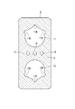
- the gasket 8 seals between the housing parts 6 and 7. Further, as shown in FIG. 5, the wall portion 9 of the gasket 8 is formed with two upper and lower passage portions 11, 12 each having a through hole in the embodiment. Each heating wire heater 4 passes through the passage portions 11 and 12 of the gasket 8 at a predetermined interval and is provided between the first housing portion 6 and the second housing portion 7.
- a heat medium inflow port 13 is formed on the upper surface of the first housing 6, and a heat medium outflow port 14 is formed on the upper surface of the second housing 7.
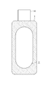
- the flow path 3 in the housing 2 constituted by the housing portions 6 and 7 has a shape in which the centers of two substantially cylindrical space portions 3A are connected by a narrow width portion 3B as shown in FIG.
- the heating wire heaters 4 in a state of passing through the passage portions 11 and 12 of the gasket 8 are respectively positioned in these space portions 3A.
- the upper surface of the upper space portion 3A and the lower surface of the lower space portion 3A are each expanded into a semicircular cross section to form a widened portion 3C.
- the gasket 8 is attached and is positioned at the approximate center between the inflow port 13 and the outflow port 14, and the lower passage portion 12 has a circular shape slightly smaller than the lower space portion 3A. Further, it has a widened portion 12A that is widened in a semicircular shape with the same shape as the lower widened portion 3C.
- the upper passage portion 11 located at the upper portion of the flow path 3 also has a circular shape that is slightly smaller than the upper space portion 3A, but reaches the upper portion, for example, the upper half of the circular arc of the space portion 3A. A plurality of narrow notches 11A are formed to protrude.
- the inner diameter dimension of the circular portions of the passage portions 11 and 12 is more than the outer diameter of the metal pipe 21 of the heating wire heater 4 in order to form a predetermined distance from the heating wire heater 4. It is set larger by a predetermined interval.
- the wall portion 9 of the gasket 8 is positioned so as to protrude from the opening end face of each housing portion 6, 7 into the flow path 3 in the housing 2, and the passage portions 11, 12 and the heating wire heater 4.
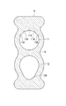
- 4 has a cross-sectional shape as shown by hatching in FIG. That is, the cross section of the flow path 3 constituted by the lower passage portion 12 has a shape that surrounds the periphery of the heating wire heater 4 at a predetermined interval and is widened downward (the widened portion 12A).
- path part 11 shows the shape where the circumference
- it passes between the 1st housing
- a heat medium flow path 3 is formed in the housing 2.
- the heat medium flows into the flow path 3 in the housing 2 as shown by the arrow in FIG. 2 from the inlet 13 by a pump or the like (not shown), passes through the flow path 3 and flows out from the outlet 14. At this time, most of the heat medium flowing in from the upper side passes from the top to the bottom of each wire heater 4 in the first housing portion 6 due to the flow, and widens the lower portion of the first housing portion 6. Part 3C is reached.
- the periphery of the lower heating wire heater 4 is directed in the direction of the gasket 8, flows into the second casing portion 7 through the widened portion 12 ⁇ / b> A of the passage portion 12 of the gasket 8, and It flows from the bottom to the top around the hot wire heater 4 and finally exits from the outlet 14. Therefore, most of the flowing heat medium smoothly passes through the widened portion 12 ⁇ / b> A of the expanded gasket 8.
- the remaining heat medium flowing in from the inlet 13 changes its direction in the direction of the gasket 8 by colliding with each of the heating wire heaters 4, and passes through the surroundings of each heating wire heater 4 to the passage portions 11 and 12 of the gasket 8.
- the air flows into the second housing part 7 from the interval between the heating wire heaters 4 and the heating wire heaters 4.
- the heat medium flows from the inlet 13 in the flow direction and then passes downward, so that it is difficult for the heat medium to flow in the upper part of the flow path 3, but the passage part on the upper side of the gasket 8. Since the plurality of cutout portions 11A protrude from the upper portion (upper half) of 11, the heat medium easily passes and the number of places where heat exchange is difficult is reduced. Further, the notch 11A has an effect of reducing pressure loss.
- the flow of the heat medium in the flow path 3 is caused by the gasket 8 that seals between the first housing portion 6 and the second housing portion 7 constituting the housing 2. Will be controlled. Therefore, it is not necessary to provide a special partition to control the flow of the heat medium in the flow path 3 or to perform special processing on the heating wire heater 4.
- the heating wire heater 4 is disposed between the housing portions 6 and 7 and penetrates the passage portions 11 and 12 formed in the wall portion 9 of the gasket 8. Flow control will be performed without any problem.
- the gasket 8 is provided with the wall portion 9 located in the flow path 3 and the passage portions 11 and 12 opened at the wall portion 9, and the lower side on which most of the heat medium flows.
- a widened portion 12A is formed in the lower portion of the passage portion 12 to increase the opening size so that the heat medium can easily flow, so that the pressure loss of the heat medium in the flow path 3 is reduced.
- the dimension of the widened portion 12A is set so that the pressure loss of the heat medium in the flow path 3 is within an allowable range.
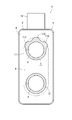
- the passage portions 11 and 12 of the gasket 8 in this case both have a circular shape larger than the outer diameter so as to be spaced apart from the heating wire heater 4, and as shown in FIG.
- a plurality of cutout portions 11B that protrude outward are formed in the upper portion of the passage portion 11, and a plurality of cutout portions 12B that protrude outward are also formed in the lower portion of the lower passage portion 12.
- These notches 11B and 12B reach the upper and lower arcs of the flow path 3.
- three small-diameter passage portions 15 are formed between the passage portions 11 and 12 in the embodiment, so that the gasket 8 has a vertically symmetrical shape with respect to the central horizontal line.
- the wall portion 9 of the gasket 8 is located so as to protrude from the opening end face of each housing portion 6, 7 into the flow path 3 in the housing 2, and the passage portions 11, 12 and the heating wire
- the flow path 3 between the heaters 4 and 4 has a cross-sectional shape as shown by hatching in FIG. That is, the cross section of the flow path 3 constituted by the lower passage portion 12 has a shape in which the periphery of the heating wire heater 4 is surrounded at a predetermined interval and the lower portion protrudes outward at a plurality of locations.
- the cross section of the flow path 3 constituted by the upper passage portion 11 also has a shape in which the periphery of the heating wire heater 4 is surrounded at a predetermined interval and the upper portion protrudes outward at a plurality of locations. And the channel
- the gasket 8 By making the gasket 8 symmetrical in the vertical direction in this way, it becomes possible to promote the equalization of the flow rate of the heat medium flowing through the flow path 3 in the housing 2 in the vertical direction.
- the notch portion 11B of the passage portion 11 has a function of increasing the flow rate of the heat medium and pushing out air.
- the pressure loss of the heat medium in the flow path 3 in this case needs to be suppressed within an allowable range. Since the heat medium also flows through the passage portion 15, the size and number of the passage portions 15 are set so that the pressure loss can be suppressed within an allowable range.
- the gasket 8 since the gasket 8 has a vertically symmetric shape, there is no need to worry about the top and bottom of the gasket 8 during assembly, and the productivity can be improved.
- FIGS. 10 and 11 show still another embodiment (Example 3) of the heating apparatus 1 of the present invention.
- or FIG. 9 shall show
- the passage portions 11 and 12 of the gasket 8 both have a circular shape larger than the outer diameter so as to have a predetermined interval between the heating wire heater 4, but only the upper passage portion 11.
- a plurality of cutout portions 11C protruding outward are formed in the upper portion, and the lower passage portion 12 remains circular.
- the cutout portion 11C reaches the arc on the upper side of the flow path 3.
- the wall portion 9 of the gasket 8 is located so as to protrude from the opening end face of each housing portion 6, 7 into the flow path 3 in the housing 2, and the passage portions 11, 12 and the heating wire
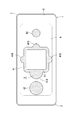
- the flow path 3 between the heaters 4 and 4 has a cross-sectional shape as shown by hatching in FIG. That is, the cross section of the flow path 3 constituted by the lower passage portion 12 has an annular shape surrounding the heating wire heater 4 at a predetermined interval.
- the cross section of the flow path 3 constituted by the upper passage portion 11 has a shape that surrounds the heating wire heater 4 at a predetermined interval, and the upper portion protrudes to the outside by a plurality of cutout portions 11C. become.
- the opening size of the upper portion of the upper passage portion 11 is expanded, so that the upper portion in the flow path 3 where the heat medium is less likely to flow than the lower portion by the flow force as described above flows. It becomes easy. Also by such a method, it becomes possible to make the flow rate of the heat medium uniform and to efficiently heat the heat medium by the heating wire heater 4. However, also in this case, the interval between the passage portion 12 and the heating wire heater 4 is particularly set so that the pressure loss of the heat medium in the flow path 3 is suppressed within an allowable range.
- FIGS. 12 to 17 show still another embodiment (Embodiment 4) of the heating apparatus 1 of the present invention.
- FIGS. 12 to 17 show still another embodiment (Embodiment 4) of the heating apparatus 1 of the present invention.
- or FIG. 11 shall show
- each side of the casings 6 and 7 constituting the casing 2 is open at one side, and each opening is abutted via a gasket 8 and fixed with bolts.
- Projecting wall portions 36 and 37 projecting from the center of the side surface to the opening at intervals are formed, and are abutted with each other.
- each heating wire heater 4 is disposed in each housing portion 6 and 7 so as to penetrate each protruding wall portion 36 and 37, respectively.
- the inflow port 13 is formed at a position close to one of the other side surfaces of the first housing portion 6, and the outflow port 14 is formed at a position close to the other of the other side surfaces of the second housing portion 7.
- the gasket 8 is positioned between the heating wire heaters 4.
- the wall portion 9 has a rectangular passage portion 41 through which the butted portions of the projecting wall portions 36 and 37 penetrate, and rounds formed on the left and right sides thereof. Passage portions 42 and 43 made up of holes are formed through.
- a predetermined interval is formed between the passage portion 41 of the gasket 8 and the projecting wall portions 36 and 37, and further, semicircular cutout portions 41A and 41B are formed on the four sides of the passage portion 41.
- the notch 41A located on the outflow port 14 side is formed larger than the other notch 41B (large opening size).
- the passage portion 42 located on the outlet 14 side has a larger diameter (larger opening size) than the passage portion 43 located on the inlet 13 side.
- the wall portion 9 of the gasket 8 in this case is also located so as to protrude from the opening end face of each housing portion 6, 7 into the flow path 3 in the housing 2, and each of the passage portions 41 to 43.
- the flow path 3 between the projecting wall portions 36 and 37 has a cross-sectional shape as shown by hatching in FIG. That is, it has a shape in which the outlet 14 side is wider than the inlet 13 side. As a result, it enters from the inlet 13 and passes between the upper and lower walls of the first casing 6 and the heating wire heater 4 and the projecting wall 36 through the passages 41 to 43 of the gasket 8 and the second casing 7.
- a flow path 3 of a heat medium that extends from between the upper and lower walls and the heating wire heater 4 and the protruding wall portion 37 to the outlet 14 is formed in the housing 2.
- the heat medium flows into the flow path 3 in the housing 2 as shown by the arrow in FIG. 13 from the inlet 13 by a pump or the like (not shown), passes through the flow path 3 and flows out from the outlet 14.
- a pump or the like not shown
- most of the heat medium flowing into the first housing portion 6 from the inlet 13 tends to pass through the passage portion 43 of the gasket 8 and the notch portion 41B of the passage portion 41 due to the flow force.
- the portion 43 and the passage portion 41B are smaller in opening size than the passage portion 42 and the cutout portion 41A on the outlet 14 side, so that about half of them cannot pass through, and the heat medium that cannot pass is directed toward the passage portion 42 and the cutout portion 41A.
- the heating medium 1 in this case also controls the flow of the heat medium in the flow path 3 by the gasket 8 that seals between the first casing 6 and the second casing 7 that constitute the casing 2. Will be. Therefore, it is not necessary to provide a special partition for controlling the flow of the heat medium in the flow path 3 or to perform special processing on the heating wire heater 4.
- the opening size of the passage portion 43 and the cutout portion 41B on the inlet 13 side which is easy to flow due to the flow of the heat medium, is larger than the passage portion 42 and the cutout portion 41A on the outlet port 14 side. It is possible to make the flow of the heat medium in the passage 3 uniform, and to efficiently perform heat exchange between each heating wire heater 4 and the heat medium. As a result, the surface temperature of the heating wire heater 4 can be prevented from rising locally, and the life of the heating wire heater 4 can be extended. Further, in this embodiment, each heating wire heater 4 is disposed in each housing portion 6, 7, but since the gasket 8 is located between each heating wire heater 4, there is no problem between the housing portions 6, 7. It is also possible to realize control of the flow of the heat medium.
- the wall portion 9 of the gasket 8 is positioned in the flow path 3, that is, the flow path 3 is temporarily moved to the first housing portion 6 side and the second housing portion 7 side by the wall portion 9. Partitions, passage portions 11, 12, 15, 41 to 43 through which the heat medium passes are formed in the wall portion 9, and the flow of the heat medium is controlled by their opening size and shape.
- a part of the wall portion 9 of the gasket 8 may be positioned so as to protrude from the end surfaces of the housing portions 6 and 7 into the flow path 3. In that case, a portion other than a portion of the wall portion 9 of the overhanging gasket 8 serves as a passage portion.
- the projecting part may be inclined with respect to the flow direction of the heat medium so as to control the ease of flow. That is, the shape of the passage portion includes an inclination of a part of the wall portion 9 of the gasket 8 and the like.
- the number of heating wire heaters 4 and the number and shape of each passage portion of the gasket 8 are not limited to the above embodiments, and heating elements other than the heating wire heaters of the embodiments are applied as heating elements. It is also possible to use a fluid other than water as the heat medium. However, by using an inexpensive general-purpose heating wire heater 4, it is possible to reduce the manufacturing cost of the heating device 1 and to improve its reliability.
- the heating device 1 of the present invention into a vehicle air conditioner for a hybrid vehicle or an electric vehicle, it is possible to improve the performance of the air conditioner provided with the cooling water circuit and the vehicle in which the cooling water circuit is mounted. Needless to say, the heating device 1 can be used as a heat source for applications other than the vehicle air conditioner.
Landscapes
- Engineering & Computer Science (AREA)
- Physics & Mathematics (AREA)
- Thermal Sciences (AREA)
- Mechanical Engineering (AREA)
- Chemical & Material Sciences (AREA)
- Combustion & Propulsion (AREA)
- General Engineering & Computer Science (AREA)
- Air-Conditioning For Vehicles (AREA)
- Instantaneous Water Boilers, Portable Hot-Water Supply Apparatuses, And Control Of Portable Hot-Water Supply Apparatuses (AREA)
Description
2 筐体
3 流路
3C 拡幅部
4 電熱線ヒータ(発熱体)
6 第1筐体部
7 第2筐体部
8 ガスケット
9 壁部
11、12、15、41、42、43 通路部
11A、11B、11C、41A、41B 切欠部
12A 拡幅部
13 流入口
14 流出口
Claims (9)
- 内部に熱媒体が流れる流路が構成された筐体と、該筐体内の流路中に配設されて前記熱媒体を加熱する発熱体とから成る加熱装置において、
前記筐体は、それぞれ少なくとも一面が開口し、各開口が相互に突き合わされた状態で接続された第1筐体部及び第2筐体部と、これら第1筐体部及び第2筐体部の突き合わせ部分に介設され、両筐体部間をシールする板状のガスケットとを備え、
該ガスケットの少なくとも一部は前記流路中に位置し、当該流路中における熱媒体の流れを制御することを特徴とする加熱装置。 - 前記ガスケットは、前記流路中に位置する壁部と、該壁部にて開口する通路部を有することを特徴とする請求項1に記載の加熱装置。
- 前記ガスケットは、前記壁部に形成された通路部の開口寸法及び又は形状により、前記筐体内で空気が溜まり易い箇所の流路を狭めることを特徴とする請求項2に記載の加熱装置。
- 前記ガスケットは、前記流路の上部に位置する前記通路部の上部に突出形成された切欠部を有することを特徴とする請求項3に記載の加熱装置。
- 前記ガスケットは、前記壁部に形成された通路部の開口寸法及び又は形状により、前記筐体内で熱媒体が流れにくい箇所の流路を広げることを特徴とする請求項2乃至請求項4のうちの何れかに記載の加熱装置。
- 前記ガスケットの壁部に形成された通路部の開口寸法及び又は形状は、前記流路中における熱媒体の圧力損失の許容範囲内で設定されることを特徴とする請求項2乃至請求項5のうちの何れかに記載の加熱装置。
- 前記発熱体は前記両筐体部間に渡って配設されており、前記ガスケットの壁部に形成された通路部を前記発熱体が貫通することを特徴とする請求項1乃至請求項6のうちの何れかに記載の加熱装置。
- 前記発熱体は前記各筐体部にそれぞれ配設されており、前記ガスケットは前記各発熱体間に位置することを特徴とする請求項1乃至請求項6のうちの何れかに記載の加熱装置。
- 前記熱媒体は、車両暖房用水回路を循環する不凍液であることを特徴とする請求項1乃至請求項8のうちの何れかに記載の加熱装置。
Priority Applications (3)
| Application Number | Priority Date | Filing Date | Title |
|---|---|---|---|
| US14/408,548 US9664412B2 (en) | 2012-07-18 | 2013-07-02 | Heating device |
| DE112013003597.9T DE112013003597T5 (de) | 2012-07-18 | 2013-07-02 | Heizvorrichtung |
| CN201380038011.2A CN104471322B (zh) | 2012-07-18 | 2013-07-02 | 加热装置 |
Applications Claiming Priority (2)
| Application Number | Priority Date | Filing Date | Title |
|---|---|---|---|
| JP2012159450A JP5967760B2 (ja) | 2012-07-18 | 2012-07-18 | 加熱装置 |
| JP2012-159450 | 2012-07-18 |
Publications (1)
| Publication Number | Publication Date |
|---|---|
| WO2014013683A1 true WO2014013683A1 (ja) | 2014-01-23 |
Family
ID=49948527
Family Applications (1)
| Application Number | Title | Priority Date | Filing Date |
|---|---|---|---|
| PCT/JP2013/004100 Ceased WO2014013683A1 (ja) | 2012-07-18 | 2013-07-02 | 加熱装置 |
Country Status (5)
| Country | Link |
|---|---|
| US (1) | US9664412B2 (ja) |
| JP (1) | JP5967760B2 (ja) |
| CN (1) | CN104471322B (ja) |
| DE (1) | DE112013003597T5 (ja) |
| WO (1) | WO2014013683A1 (ja) |
Cited By (1)
| Publication number | Priority date | Publication date | Assignee | Title |
|---|---|---|---|---|
| FR3033871A1 (fr) * | 2015-03-20 | 2016-09-23 | Valeo Systemes Thermiques | Dispositif de chauffage electrique de fluide |
Families Citing this family (4)
| Publication number | Priority date | Publication date | Assignee | Title |
|---|---|---|---|---|
| US10107490B2 (en) | 2014-06-30 | 2018-10-23 | Lam Research Corporation | Configurable liquid precursor vaporizer |
| US9982341B2 (en) * | 2015-01-30 | 2018-05-29 | Lam Research Corporation | Modular vaporizer |
| FR3091579A1 (fr) * | 2019-01-07 | 2020-07-10 | Valeo Systemes Thermiques | Dispositif de chauffage électrique et de circulation d’un liquide pour véhicule automobile |
| EP4283211B1 (en) * | 2022-05-25 | 2026-04-29 | Valeo Electrification | An electrical fluid heater |
Citations (1)
| Publication number | Priority date | Publication date | Assignee | Title |
|---|---|---|---|---|
| JP2009156507A (ja) * | 2007-12-26 | 2009-07-16 | Takahata Seiko Kk | 流体加熱装置 |
Family Cites Families (44)
| Publication number | Priority date | Publication date | Assignee | Title |
|---|---|---|---|---|
| US941215A (en) * | 1908-09-02 | 1909-11-23 | George H Wade | Water-heater. |
| US1215748A (en) * | 1915-12-14 | 1917-02-13 | Wilmot Castle Co | Electric heater. |
| US2640138A (en) * | 1951-10-26 | 1953-05-26 | Universal Engine Heater Compan | Heater for the coolant liquid of internal-combustion engines |
| US3262570A (en) * | 1963-02-05 | 1966-07-26 | Commercial Filter Corp | Filtration assemblies and replaceable elements of such assemblies |
| US3863021A (en) * | 1970-09-03 | 1975-01-28 | Nelco Corp | Molded electrical junction box |
| US4201360A (en) * | 1978-01-27 | 1980-05-06 | Packer Plastics, Inc. | Injection molding of embossed articles |
| DE2804784A1 (de) * | 1978-02-04 | 1979-08-09 | Eichenauer Fa Fritz | Elektrische widerstandsheizeinrichtung |
| DE2804818C2 (de) * | 1978-02-04 | 1986-12-11 | Fritz Eichenauer GmbH & Co KG, 6744 Kandel | Elektrische Heizeinrichtung |
| JPS5683560A (en) * | 1979-12-12 | 1981-07-08 | Nissan Shatai Co Ltd | Heating apparatus for mixture of gasoline engine |
| US4349434A (en) * | 1980-01-07 | 1982-09-14 | Jaworski William R | Filtration system for spas, hot tubs, swimming pools and the like |
| US4395618A (en) * | 1980-03-03 | 1983-07-26 | Emerson Electric Co. | Electric circulation heater for heating fluids such as oil |
| DE3374537D1 (en) * | 1982-09-24 | 1987-12-23 | Onofrio Rocchitelli | Heating device for the glass washing fluid of motor vehicles and the like |
| JPS6098766A (ja) | 1983-11-02 | 1985-06-01 | Ricoh Co Ltd | フアクシミリ装置における誤り訂正方式 |
| JPS6098766U (ja) * | 1983-12-12 | 1985-07-05 | トヨタ自動車株式会社 | エンジンの吸気加熱冷却装置 |
| JPH0816435B2 (ja) | 1991-03-06 | 1996-02-21 | 株式会社奥村組 | シールド掘削機 |
| IT1259525B (it) | 1992-04-07 | 1996-03-20 | Carlo Alberto Prosino | Procedimento per l'indurimento superficiale di anelli di acciaio per filatoi, ed anello trattato mediante tale procedimento |
| JPH0649721U (ja) * | 1992-12-09 | 1994-07-08 | 日産自動車株式会社 | 内燃機関の排気管 |
| US5438642A (en) * | 1993-07-13 | 1995-08-01 | Instantaneous Thermal Systems, Inc. | Instantaneous water heater |
| US5549821A (en) * | 1993-09-29 | 1996-08-27 | Fleetguard, Inc. | Fluid filter assembly for vehicles |
| US6419476B1 (en) * | 1998-08-25 | 2002-07-16 | Joseph P. Ouellette | Thermally insulated runner manifold and injection nozzle construction for plastic molding apparatus |
| JP3633329B2 (ja) | 1998-11-18 | 2005-03-30 | 東陶機器株式会社 | 瞬間加熱式温水装置 |
| US6330395B1 (en) * | 1999-12-29 | 2001-12-11 | Chia-Hsiung Wu | Heating apparatus with safety sealing |
| JP2001235033A (ja) * | 2000-02-22 | 2001-08-31 | Ishikawa Gasket Co Ltd | ガスケット |
| DE10023427A1 (de) * | 2000-05-12 | 2001-11-15 | Mann & Hummel Filter | Flüssigkeitsfilter mit in Urformtechnik hergestelltem Gehäuse und Verfahren zu seiner Herstellung |
| US6816670B1 (en) * | 2001-03-19 | 2004-11-09 | Renau Corporation | Fluid heat exchanging system and method |
| US6957013B2 (en) * | 2001-06-08 | 2005-10-18 | Algas-Sdi International Llc | Fluid heater |
| AU2002313719A1 (en) * | 2001-08-03 | 2003-02-24 | Integrated Circuit Development Corporation | In-line fluid heating system |
| AU2003296942A1 (en) * | 2002-12-11 | 2004-06-30 | Thomas Johnston | Method device for heating fluids |
| DE10356790A1 (de) * | 2003-12-04 | 2005-07-07 | BSH Bosch und Siemens Hausgeräte GmbH | Heizvorrichtung für Fluide, Durchlauferhitzer und Verfahren zu deren Herstellung |
| US7822326B2 (en) * | 2004-02-05 | 2010-10-26 | Graco Minnesota, Inc. | Hybrid heater |
| US7046922B1 (en) * | 2005-03-15 | 2006-05-16 | Ion Tankless, Inc. | Modular tankless water heater |
| JP2007010255A (ja) | 2005-07-01 | 2007-01-18 | Matsushita Electric Ind Co Ltd | 流体加熱装置およびそれを用いた給湯装置 |
| JP2007128751A (ja) * | 2005-11-04 | 2007-05-24 | Tokuden Co Ltd | 流体加熱装置及びその装置を使用した熱媒体通流ローラ装置 |
| KR100825825B1 (ko) * | 2006-12-13 | 2008-04-28 | 한경희 | 순간 가열식 스팀보일러 |
| US8061263B1 (en) * | 2007-04-16 | 2011-11-22 | Richard W. Hein | Sensor head and brew cup for a beverage brewing device |
| US7668444B2 (en) * | 2007-07-31 | 2010-02-23 | Hua-Hsin Tsai | Pipe heater encircled conduit device |
| KR100880773B1 (ko) * | 2008-01-23 | 2009-02-02 | (주) 씨엠테크 | 유체 가열장치 |
| JP5415797B2 (ja) * | 2009-03-24 | 2014-02-12 | 株式会社Kelk | 流体加熱装置 |
| DE102009016601B4 (de) * | 2009-04-08 | 2025-07-17 | Mann+Hummel Gmbh | Filtereinrichtung für Fluide, insbesondere für Kraftstoffe |
| JP4706986B2 (ja) | 2009-07-01 | 2011-06-22 | 三菱自動車工業株式会社 | 流路部材構造 |
| DE102009038978A1 (de) * | 2009-08-21 | 2011-03-03 | Beru Ag | Vorrichtung zum Erwärmen von Flüssigkeiten |
| JP2011143781A (ja) | 2010-01-13 | 2011-07-28 | Sanden Corp | 加熱装置 |
| EP2440005B1 (de) * | 2010-10-08 | 2015-12-23 | Eberspächer catem GmbH & Co. KG | Elektrische Heizvorrichtung und Verfahren zur Herstellung |
| US8731386B2 (en) * | 2011-09-30 | 2014-05-20 | Borgwarner Beru Systems Gmbh | Electric heating device for heating fluids |
-
2012
- 2012-07-18 JP JP2012159450A patent/JP5967760B2/ja active Active
-
2013
- 2013-07-02 DE DE112013003597.9T patent/DE112013003597T5/de active Pending
- 2013-07-02 US US14/408,548 patent/US9664412B2/en active Active
- 2013-07-02 WO PCT/JP2013/004100 patent/WO2014013683A1/ja not_active Ceased
- 2013-07-02 CN CN201380038011.2A patent/CN104471322B/zh active Active
Patent Citations (1)
| Publication number | Priority date | Publication date | Assignee | Title |
|---|---|---|---|---|
| JP2009156507A (ja) * | 2007-12-26 | 2009-07-16 | Takahata Seiko Kk | 流体加熱装置 |
Cited By (1)
| Publication number | Priority date | Publication date | Assignee | Title |
|---|---|---|---|---|
| FR3033871A1 (fr) * | 2015-03-20 | 2016-09-23 | Valeo Systemes Thermiques | Dispositif de chauffage electrique de fluide |
Also Published As
| Publication number | Publication date |
|---|---|
| CN104471322A (zh) | 2015-03-25 |
| US9664412B2 (en) | 2017-05-30 |
| US20150131981A1 (en) | 2015-05-14 |
| JP5967760B2 (ja) | 2016-08-10 |
| DE112013003597T5 (de) | 2015-04-16 |
| JP2014019286A (ja) | 2014-02-03 |
| CN104471322B (zh) | 2017-06-09 |
Similar Documents
| Publication | Publication Date | Title |
|---|---|---|
| JP5967760B2 (ja) | 加熱装置 | |
| US9546827B2 (en) | Device for conducting a cooling fluid, and cooling system for cooling an electrical component | |
| KR101372256B1 (ko) | 냉각수 가열식 히터 | |
| JP6144522B2 (ja) | 温調装置 | |
| CN103974839B (zh) | 用于机动车辆的电加热装置和相关联的空调和/或加热单元 | |
| WO2014013684A1 (ja) | 加熱装置及び加熱装置の製造方法 | |
| US20160010534A1 (en) | Complex heat exchanger | |
| JP6088708B2 (ja) | 接続モジュール、熱交換器、および対応する熱交換アセンブリ | |
| KR20170073973A (ko) | 냉각수 히터 | |
| EP2731236B1 (en) | Motor | |
| JP2013256274A (ja) | 加熱装置 | |
| JP5962570B2 (ja) | 回転電機 | |
| KR102415658B1 (ko) | 전기차량의 냉각수 가열장치 | |
| US11378000B2 (en) | Coolant heater for a vehicle | |
| JP6582546B2 (ja) | 機電一体型回転電機 | |
| KR20200057857A (ko) | 차량용 냉각 장치 | |
| JP2014173747A (ja) | 複合型熱交換器 | |
| JP2014194319A (ja) | 熱交換器 | |
| KR20180005433A (ko) | 냉각수 히터 | |
| JP2017009280A (ja) | 消イオン化カートリッジを有する熱交換器 | |
| JP2014173748A (ja) | 複合型熱交換器 | |
| KR20130142647A (ko) | 냉각수 가열식 히터 | |
| EP4526141A1 (en) | Automotive coolant supply device | |
| JP2021020509A (ja) | 熱媒体加熱装置 | |
| KR20160134220A (ko) | 차량용 공조장치 |
Legal Events
| Date | Code | Title | Description |
|---|---|---|---|
| 121 | Ep: the epo has been informed by wipo that ep was designated in this application |
Ref document number: 13820677 Country of ref document: EP Kind code of ref document: A1 |
|
| WWE | Wipo information: entry into national phase |
Ref document number: 14408548 Country of ref document: US |
|
| WWE | Wipo information: entry into national phase |
Ref document number: 1120130035979 Country of ref document: DE Ref document number: 112013003597 Country of ref document: DE |
|
| 122 | Ep: pct application non-entry in european phase |
Ref document number: 13820677 Country of ref document: EP Kind code of ref document: A1 |