WO2014013650A1 - 鉄道車両の脱線検知装置及び鉄道車両 - Google Patents
鉄道車両の脱線検知装置及び鉄道車両 Download PDFInfo
- Publication number
- WO2014013650A1 WO2014013650A1 PCT/JP2013/002802 JP2013002802W WO2014013650A1 WO 2014013650 A1 WO2014013650 A1 WO 2014013650A1 JP 2013002802 W JP2013002802 W JP 2013002802W WO 2014013650 A1 WO2014013650 A1 WO 2014013650A1
- Authority
- WO
- WIPO (PCT)
- Prior art keywords
- derailment
- movable member
- obstacle
- derailment detection
- detection device
- Prior art date
- Legal status (The legal status is an assumption and is not a legal conclusion. Google has not performed a legal analysis and makes no representation as to the accuracy of the status listed.)
- Ceased
Links
Images



Classifications
-
- B—PERFORMING OPERATIONS; TRANSPORTING
- B61—RAILWAYS
- B61F—RAIL VEHICLE SUSPENSIONS, e.g. UNDERFRAMES, BOGIES OR ARRANGEMENTS OF WHEEL AXLES; RAIL VEHICLES FOR USE ON TRACKS OF DIFFERENT WIDTH; PREVENTING DERAILING OF RAIL VEHICLES; WHEEL GUARDS, OBSTRUCTION REMOVERS OR THE LIKE FOR RAIL VEHICLES
- B61F9/00—Rail vehicles characterised by means for preventing derailing, e.g. by use of guide wheels
- B61F9/005—Rail vehicles characterised by means for preventing derailing, e.g. by use of guide wheels by use of non-mechanical means, e.g. acoustic or electromagnetic devices
Definitions
- the present invention relates to a railcar derailment detection device and a railcar equipped with the same.
- a derailment detection sensor having an operation piece such as a micro switch is used. At the time of derailment, the operation piece rotates to be turned ON, and an alarm is activated to issue an alarm. What was made is known (for example, refer to Patent Document 1).
- a derailment detection device is a derailment detection device provided at a front end portion of a carriage, and a movable member that moves in a predetermined direction by the action of a load of a predetermined value or more and contact with a track when the carriage is derailed.
- a derailment detection member that transmits the received load greater than the predetermined value to the movable member and moves the movable member in a predetermined direction, and a derailment detection line that conducts electricity or light to detect derailment of the carriage.
- the derailment detection line comprised so that an electric conduction state or a light conduction state may be interrupted
- derailment can be detected at low cost with a simple configuration of a movable member, a derailment detection member, and a derailment detection line. Further, derailment can be detected without using a special specification sensor or the like.
- a railcar according to the present invention is a derailment detection device for the railcar described above, and a derailment detection circuit connected to the derailment detection line of the derailment detector, wherein the derailment detection line is in an electrically conductive state or light.
- a derailment detection circuit including a relay that operates when the conduction state is interrupted, and a brake that operates in conjunction with the operation of the relay.
- the present invention can provide a railcar derailment detection device that can detect derailment at a low cost with a simple configuration without using a special specification sensor, and a railcar including the railcar derailment detection device.
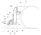
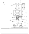
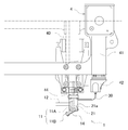
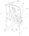
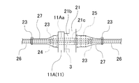
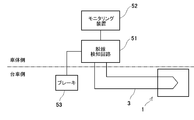
- FIG. 1 It is a side view of the bogie for rail vehicles provided with the derailment detection device of a rail vehicle. It is an enlarged view of the A section of FIG. It is a front view of the A section of FIG. It is a top view of the A section of FIG. It is a perspective view of a derailment detection device. It is an enlarged view of a fixed member and a movable member at a position where a derailment detection line is passed. (A) (b) is the front view and side view of a derailment detection apparatus which show the state at the time of derailment, respectively. It is a block diagram of the part regarding the derailment detection apparatus in a railway vehicle.
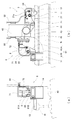
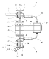
- (A) and (b) are a front view and a side view, respectively, of a part of a railcar carriage provided with a railcar derailment detection device and an obstacle detection device. It is a partial cross section top view of a derailment detection device and an obstacle detection device. It is a block diagram of the part regarding the derailment detection apparatus and obstacle detection apparatus in a railway vehicle.
- FIG. 1 is a side view of a railcar bogie provided with a railcar derailment detection device
- FIGS. 2 to 4 are enlarged views, front views and plan views, respectively, of FIG. 1
- FIG. 5 is a perspective view of the derailment detection device.
- FIG. The concept of the direction in the following description corresponds to the concept of the direction when the traveling direction of the railway vehicle is the front and the front is facing the front. That is, the vehicle longitudinal direction corresponds to the front-rear direction, and the vehicle width direction corresponds to the left-right direction.
- a derailment detection device 1 for detecting a derailment of a railway vehicle is provided at a front end portion (front side in the vehicle traveling direction) of a railcar carriage 4 (hereinafter also simply referred to as a “trolley”). And located in front of the wheel 40.
- the derailment detection device 1 includes a fixed member 21, a movable member 11, a detection arm 12 that functions as a derailment detection member, and a derailment detection line 3.
- column members 42 hang from both ends of the front surface of the carriage frame 41 of the carriage 4 in the vehicle width direction.
- a beam member 43 is provided.
- these members 42 and 43 constitute the front end portion of the carriage 4.
- the derailment detection device 1 is attached to a support bracket 44 that protrudes forward from the tip of the beam member 43.
- the fixing member 21 is fixed to the beam member 43 via the support bracket 44.
- the fixing member 21 has a T shape in a plan view, and protrudes forward from a substantially central portion of the base portion, which is fastened by a support bracket 44 and a bolt. And a flat plate portion in the vehicle width direction.
- the fixing member 21 is integrally formed with a cover 21a that covers the plate portion from above and from the front and has a width approximately the same as the base portion.
- a base portion 21b (see FIG. 6) is provided in a region overlapping with the movable member 11 on the main surface on the inner side in the vehicle width direction of the plate portion of the fixed member 21.
- the movable member 11 is disposed at a position above the track R when the railcar travels on the track. Specifically, as shown in FIG. 5, the movable member 11 has a main body portion 11A and an attachment portion 11B.
- the main body 11 ⁇ / b> A has a plate shape extending in the longitudinal direction of the vehicle parallel to the plate portion of the fixing member 21.
- the main body portion 11 ⁇ / b> A is fastened to the plate portion of the fixing member 21 by a mounting bolt 22 that extends in the vehicle width direction and a nut that is screwed to the mounting bolt 22.
- the movable member 11 can rotate around the mounting bolt 22. That is, the mounting bolt 22 functions as a rotating shaft.
- the movable member 11 is configured to rotate (move) in a predetermined direction B by the action of a load greater than or equal to a predetermined value, thanks to a hollow bolt 24 described later.
- a through hole 11Aa (see FIG. 6) is formed at a position shifted from the center of rotation in an area overlapping with the plate portion of the fixing member 21.
- the through-hole 21c (refer FIG. 6) is formed in the plate part and the base part 21b of the fixing member 21 in the position corresponding to the through-hole 11Aa.
- a part of the derailment detection line 3 is inserted into the through holes 11Aa and 21c.
- the attachment part 11B is a plate-like shape that is inclined with respect to the main body part 11A so as to be located rearward as it becomes the vehicle outer side. And the left-right direction center part of the attachment part 11B is connected with the front-end part of 11 A of main-body parts.
- a plate-shaped obstacle plate 14 (for example, a rubber plate embedded with a reinforcing cloth) is attached to the attachment portion 11B so as to hang down. You can eliminate things.
- the detection arm 12 has a rod shape, for example, and protrudes from the side surface of the main body 11A of the movable member 11 toward the vehicle inner side. Note that the detection arm 12 may protrude not on the vehicle inner side but on the vehicle outer side.
- the base end of the detection arm 12 is fixed to the side surface of the main body 11A by welding or the like.
- the detection arm 12 extends in a substantially horizontal direction to a position corresponding to the vicinity of the side edge of the rail fastening device 15.
- the detection arm 12 is disposed obliquely rearward when viewed from the mounting bolt 22 described above.
- the detection arm 12 receives a load of a predetermined value or more due to contact with the track R when the carriage 4 is derailed, and transmits the load to the movable member 11. Thereby, the movable member 11 fixed to the detection arm 12 rotates.
- the derailment detection line 3 conducts electricity or light.
- the derailment detection line 3 is connected to a derailment detection circuit 51 provided on the vehicle body side, and when the derailment detection circuit 51 detects derailment, the information is monitored.
- the derailment detection circuit 51 includes a relay that operates when the electrical conduction state or the light conduction state of the derailment detection line 3 is interrupted. When the relay is operated, the brake 53 is operated as an emergency brake in conjunction with this.
- the derailment detection line 3 may be an optical fiber that conducts light.
- both ends of the derailment detection line 3 are connected to the derailment detection circuit 51 via a light emitter that converts electricity into light and a light receiver that converts light into electricity.
- electrical wiring is used as the derailment detection line 3
- noise may be given to signal equipment and electrical equipment.
- an optical fiber is used, generation of such noise can be prevented.
- the derailment detection line 3 is bundled as a single wire 30 in most of the forward path and the return path so as to form a string having a ring at the tip.
- the wire rod 30 is disposed along the column member 42, and the ring portion formed by the central portion of the derailment detection line 3 intersects the plate portion of the fixing member 21 twice. More specifically, the derailment detection line 3 passes through a through hole provided at an upper position of the plate portion of the fixed member 21 and a continuous hole including the through hole 11Aa of the movable member 11 and the through hole 21c of the fixed member 21 described above. Has been taken over.
- the shaft portion of the hollow bolt 24 is inserted into the through hole 11 ⁇ / b> Aa of the movable member 11 and the through hole 21 c of the fixed member 21.
- the hollow bolt 24 penetrates the main body portion 11 ⁇ / b> A of the movable member 11 and the pedestal portion 21 b and the plate portion of the fixed member 21.
- a nut 25 is screwed onto the shaft portion of the hollow bolt 24, thereby fastening the movable member 11 and the plate portion of the fixed member 21.
- the derailment detection line 3 is inserted through the hollow bolt 24.
- the derailment detection line 3 exposed from the hollow bolt 24 is covered with a rubber hose 26.
- the derailment detection line 3 is covered with the heat shrinkable tube 27 at the exit portions of the through holes 11Aa and 21c.
- the movable member 11 rotates and the through hole 11Aa of the movable member 11 is fixed to the fixed member 21.
- the hollow bolt 24 is broken by shifting from the through hole 21c. That is, the strength of the hollow bolt 24 is set so that the hollow bolt 24 is broken when a load of a predetermined value or more acts.
- the predetermined value is the breaking strength of the hollow bolt 24.
- the load for moving the movable member 11 is, for example, a static load of about 1 ton, but can be variously changed depending on the diameter of the hollow bolt 24, the distance from the rotation center, and the like. Good.
- the obstacle detection circuit 51 detects the derailment
- the obstacle detection may be performed by using the obstacle board 14. That is, since the obstacle plate 14 is attached to the movable member 11 (attachment portion 11B), the obstacle plate 14 may collide with an obstacle on the line R and receive a load of a predetermined value or more from the obstacle.
- the movable member 11 receives a load of a predetermined value or more through the obstacle plate 14 and rotates in a predetermined direction to break the hollow bolt 24.
- the derailment detection line 3 is cut by the breakage of the hollow bolt 24 and the electrical conduction state is interrupted. Even if the evacuation plate 14 collides with an obstacle on the line R, the movable member 11 does not rotate by simply removing it from the line R if it is an obstacle such as a ballast.
- the derailment detection device 1 has a simple configuration in which the movable arm 11 is rotated by bringing the detection arm 12 into contact with the track R when the carriage 4 is derailed, and the derailment detection circuit 51 electrically detects the rotation. Derailment can be detected.
- the derailment detection sensor when a derailment detection sensor (microswitch) is attached to the carriage 4 to detect derailment as in the prior art, the derailment detection sensor is reliably prevented from being damaged by vibration of the carriage 4 or the like. It is necessary to use a sensor with a special specification for the above, but according to each of the above-mentioned configurations, it can be avoided, which is advantageous in terms of cost.
- derailment is detected with a simple configuration in which a detection arm 12 (derailment detection member) that protrudes from the side surface of the movable member 11 to the vehicle inner side (or vehicle outer side) is provided. Can be activated.
- derailment detection and obstacle detection can be performed by the common movable member 11 and the derailment detection line 3, so that the structure can be simplified.
- the derailment is detected by cutting the derailment detection line 3 (hollow bolt 24) by a simple operation of rotating the movable member 11, the detection can be performed at a low cost without using a special specification sensor.
- the movable member 11 does not rotate unless it receives a load of a predetermined value or more, it does not rotate during normal traveling, and the electrical conduction state of the derailment detection line 3 is not inadvertently interrupted.
- FIGS. 9A and 9B are a front view and a side view of a part of the railcar carriage 4 provided with the derailment detection device 1 and the obstacle detection device 6, respectively, and FIG. 10 shows the derailment detection device 1 and the obstacle detection.
- 3 is a partial cross-sectional plan view of the device 6.
- the support bracket 44 for the derailment detection device 1 protrudes backward from the tip of the beam member 43, while the support bracket 45 for the obstacle detection device 6 protrudes forward from the tip of the beam member 43. .
- the derailment detection device 1 is configured in the same manner as in the above embodiment except that the movable member 11 is composed only of a plate-like portion parallel to the plate portion of the fixed member 21. That is, only the detection arm 12 is attached to the movable member 11.
- the obstacle detection device 6 has the same configuration as the derailment detection device 1 of the above embodiment except that the detection arm 12 is not provided. That is, the obstacle detection device 6 includes a fixing member 71 fixed to the beam member 43 via the support bracket 45, a cover 72 formed integrally with the fixing member 71, and a movable member connected to the fixing member 71. (Second movable member) 61 and an obstacle detection line 8 are provided.
- the movable member 61 has a plate-like main body portion 61A extending in the longitudinal direction of the vehicle fastened by the plate portion of the fixed member 71, the mounting bolt 22 and the nut, and the obstacle plate 14 inclined with respect to the main body portion 61A. And an attachment portion 61B attached. That is, the movable member 61 can rotate around the mounting bolt 22. Further, the movable member 61 is fastened to the plate portion of the fixed member 71 by the hollow bolt 24 and the nut 25 similarly to the configuration shown in FIG. Thereby, the movable member 61 rotates (moves) in a predetermined direction by the action of a load equal to or greater than a predetermined value.
- the obstacle detection line 8 is inserted through the hollow bolt 24.
- the obstacle detection line 8 conducts electricity or light.
- the movable member 61 is rotated by receiving a load of a predetermined value or more from the obstacle on the track R when the railway vehicle is running, The light conducting state is interrupted. Thereby, an obstacle can be detected.
- the obstacle detection line 8 is connected to an obstacle detection circuit 54 provided on the vehicle body side, and when the obstacle detection circuit 54 detects an obstacle, Information is displayed on the monitoring device 52.
- the obstacle detection circuit 54 includes a relay that operates when the electric conduction state or the light conduction state of the obstacle detection line 8 is interrupted. When the relay is operated, the brake 53 is operated as an emergency brake in conjunction with this.
- the obstacle detection line 8 an electrical wiring that conducts electricity may be used, or an optical fiber that conducts light may be used. In the latter case, both ends of the derailment detection line 8 are connected to the obstacle detection circuit 54 via a projector that converts electricity into light and a light receiver that converts light into electricity.
- the obstacle detection line 8 is mostly bundled as a single wire 80 so as to form a string having a ring at the tip.
- the wire 80 is disposed along the column member 42, and the ring portion formed by the central portion of the obstacle detection line 8 intersects the plate portion of the fixing member 61 twice. Similar to the configuration shown in FIG.
- the movable member 61 is provided with a through hole 11 ⁇ / b> Aa, and the plate portion and the base portion 21 b of the fixed member 21 are provided with a through hole 21 c.
- the shaft portion of the hollow bolt 24 is inserted into the through hole 11 ⁇ / b> Aa of the movable member 61 and the through hole 21 c of the fixed member 21.
- derailment detection and obstacle detection can be performed separately using the movable member 11 of the derailment detection device 1.
- the obstacle detection line 8 may be added to the derailment detection device 1 shown in FIGS. 1 to 5 and the obstacle detection circuit 54 may be added to the vehicle body side.
- the addition of the obstacle detection line 8 to the derailment detection device 1 means that two hollow bolts 24 are provided for one movable member 11.
- the movable member 11 of the derailment detection device 1 and / or the movable member 61 of the obstacle detection device 6 do not necessarily need to rotate, but move (linear movement, bending movement, etc.) to move the derailment detection line 3 and / or The obstacle detection line 8 may be cut.
- the derailment detection line 3 and / or the obstacle detection line 8 do not need to penetrate both the through holes 11Aa and 21a, and may only penetrate one of the through holes. Moreover, it can also arrange
- the brake 53 is operated as an emergency brake.
- the present invention is not limited to this.
- a warning light on a driver's seat may be turned on or an alarm device may be sounded.
- the detection arm 12 as the derailment detection member may be a columnar shape, a prismatic shape, a plate shape, a box shape, or the like, as long as it has a shape capable of detecting derailment.
- the fixing member 21 does not necessarily need to be a separate body from the carriage 4, and may be formed integrally with a part of the carriage 4.
- the factor that interrupts the electrical conduction state or the light conduction state of the derailment detection line 3 is not necessarily limited to the disconnection of the derailment detection line 3.
- the derailment detection line 3 is divided into a line part on the fixed member 21 side and a line part on the movable member 11 side, and those line parts are connected to each other via a connector, and the movable member 11 moves.
- the connector may be separated. This also applies to the obstacle detection line 8.
- the predetermined value for moving the movable member 11 of the derailment detection device 1 and / or the movable member 61 of the obstacle detection device 6 in a predetermined direction is not necessarily the breaking strength of the hollow bolt 24 and can be selected as appropriate. is there. For example, you may employ
Landscapes
- Physics & Mathematics (AREA)
- Acoustics & Sound (AREA)
- Electromagnetism (AREA)
- Engineering & Computer Science (AREA)
- Mechanical Engineering (AREA)
- Train Traffic Observation, Control, And Security (AREA)
- Regulating Braking Force (AREA)
Abstract
脱線検知装置(1)は台車(4)の前端部に設けられる。この装置(1)は、可動部材(11)と、脱線検知部材としての検知アーム(12)と、脱線検知線(3)とを備える。可動部材(11)は、所定値以上の荷重の作用により所定方向に移動する。検知アーム(12)が台車(4)の脱線時に線路との接触により前記所定値以上の荷重を受けると、それを伝達された可動部材(11)は所定方向に移動する。脱線検知線(3)は、台車(4)の脱線時に、可動部材(11)の移動により、電気導通状態又は光導通状態が遮断されるように構成されている。
Description
本発明は、鉄道車両の脱線検知装置及びこれを備えた鉄道車両に関するものである。
従来、鉄道車両の脱線検知装置として、例えばマイクロスイッチのような作動片を有する脱線検出センサを用い、脱線時に、前記作動片が回動してON作動し、警報器を作動して警報を発するようにしたものが知られている(例えば特許文献1参照)。
特許文献1記載の技術のように、脱線検出センサを用いて、脱線を検出する構成では、台車の振動などによりセンサが破損しやすい。そのため、非常に丈夫な特殊仕様のセンサとする必要があり、高価となる。
本発明は、そのような特殊仕様のセンサを用いることなく、簡易な構成で安価に脱線を検知することができる鉄道車両の脱線検知装置及びこれを備えた鉄道車両を提供することを目的とする。
本発明に係る脱線検知装置は、台車の前端部に設けられる脱線検知装置であって、所定値以上の荷重の作用により所定方向に移動する可動部材と、前記台車の脱線時に線路との接触により受けた前記所定値以上の荷重を前記可動部材に伝達して、前記可動部材を所定方向に移動させる脱線検知部材と、前記台車の脱線を検知するための、電気又は光を導通する脱線検知線であって、前記台車の脱線時に、前記可動部材の移動により、電気導通状態又は光導通状態が遮断されるように構成された脱線検知線と、を備える。
このようにすれば、可動部材、脱線検知部材及び脱線検知線という簡単な構成で、脱線を安価に検知できる。また、特殊仕様のセンサ等を用いることなく脱線を検知することができる。
また、本発明に係る鉄道車両は、上記の鉄道車両の脱線検知装置と、前記脱線検知装置の前記脱線検知線と接続された脱線検知回路であって、前記脱線検知線の電気導通状態又は光導通状態が遮断されると作動するリレーを含む脱線検知回路と、前記リレーの作動に連動して作動するブレーキと、を備える。
本発明は、特殊仕様のセンサを用いることなく、簡易な構成で安価に脱線を検知することができる鉄道車両の脱線検知装置及びこれを備えた鉄道車両を提供することができる。
以下、実施の形態を図面に沿って説明する。
[1.脱線検知装置の構成]
[1-1.全体構成の概略]
図1は鉄道車両の脱線検知装置が設けられた鉄道車両用台車の側面図、図2~4はそれぞれ図1のA部の拡大図、正面図及び平面図、図5は脱線検知装置の斜視図である。以下の説明における方向の概念は、鉄道車両の進行方向を前方とし、前方を向いたときの方向の概念と一致している。すなわち、車両長手方向が前後方向に対応し、車幅方向が左右方向に対応している。
[1.脱線検知装置の構成]
[1-1.全体構成の概略]
図1は鉄道車両の脱線検知装置が設けられた鉄道車両用台車の側面図、図2~4はそれぞれ図1のA部の拡大図、正面図及び平面図、図5は脱線検知装置の斜視図である。以下の説明における方向の概念は、鉄道車両の進行方向を前方とし、前方を向いたときの方向の概念と一致している。すなわち、車両長手方向が前後方向に対応し、車幅方向が左右方向に対応している。
図1~図5において、鉄道車両の脱線を検知するための脱線検知装置1は、鉄道車両用台車4(以下、単に「台車」ともいう)の前端部(車両進行方向の前側)に設けられており、車輪40の前方に位置している。この脱線検知装置1は、固定部材21と、可動部材11と、脱線検知部材として機能する検知アーム12と、脱線検知線3とを備える。
図1~4に示すように、台車4の台車枠41における前面の車幅方向の両端部からは、柱部材42が垂れ下がっており、この柱部材42の下部には、車幅方向内側に延びる梁部材43が設けられている。本実施形態では、これらの部材42,43によって台車4の前端部が構成されている。そして、脱線検知装置1は、梁部材43の先端から前方に突出する支持ブラケット44に取り付けられている。
[1-2.固定部材21の構成]
固定部材21は、支持ブラケット44を介して梁部材43に固定されている。具体的に、固定部材21は、図5に示すように、平面視でT字状をなしており、支持ブラケット44とボルトにより締結されるベース部と、このベース部の略中央から前方に突出する、車幅方向に扁平なプレート部を有している。また、固定部材21には、プレート部を上方及び前方から覆う、ベース部と同程度の幅のカバー21aが一体的に形成されている。固定部材21のプレート部の車幅方向内側の主面には、可動部材11と重なり合う領域に台座部21b(図6参照)が設けられている。
固定部材21は、支持ブラケット44を介して梁部材43に固定されている。具体的に、固定部材21は、図5に示すように、平面視でT字状をなしており、支持ブラケット44とボルトにより締結されるベース部と、このベース部の略中央から前方に突出する、車幅方向に扁平なプレート部を有している。また、固定部材21には、プレート部を上方及び前方から覆う、ベース部と同程度の幅のカバー21aが一体的に形成されている。固定部材21のプレート部の車幅方向内側の主面には、可動部材11と重なり合う領域に台座部21b(図6参照)が設けられている。
[1-3.可動部材11の構成]
図2および図3に示すように、可動部材11は、鉄道車両の線路走行時において線路Rの上方となる位置に配置されている。具体的に、可動部材11は、図5に示すように、本体部11Aと、取付部11Bとを有している。
図2および図3に示すように、可動部材11は、鉄道車両の線路走行時において線路Rの上方となる位置に配置されている。具体的に、可動部材11は、図5に示すように、本体部11Aと、取付部11Bとを有している。
本体部11Aは、固定部材21のプレート部と平行な、車両長手方向に延在する板状である。本体部11Aは、車幅方向に延びる取付ボルト22及びこの取付ボルト22と螺合するナットにより、固定部材21のプレート部と締結されている。これにより、可動部材11が取付ボルト22回りに回転可能となっている。すなわち、取付ボルト22は回転軸として機能する。また、可動部材11は、後述する中空ボルト24のおかげで、所定値以上の荷重の作用により所定方向Bに回転(移動)するように構成されている。
本体部11Aには、固定部材21のプレート部と重なり合う領域における回転中心よりずれた位置に貫通穴11Aa(図6参照)が形成されている。また、固定部材21のプレート部及び台座部21bにも、貫通穴11Aaに対応する位置に貫通穴21c(図6参照)が形成されている。これらの貫通穴11Aa,21cには、後述するように、脱線検知線3の一部が挿通されている。
取付部11Bは、車両外側になるほど後方に位置するように本体部11Aに対して傾斜した板状である。そして、取付部11Bの左右方向中央部が本体部11Aの前端部に連設されている。
また、取付部11Bには、板状の排障板14(例えば補強布を埋設したゴム板)が垂下するように取り付けられ、鉄道車両の走行時に、この排障板14によって線路R上の障害物を排除できるようになっている。
[1-4.検知アーム12の構成]
検知アーム12は、例えば棒状であり、可動部材11の本体部11Aの側面から車両内方側に突出している。なお、検知アーム12は、車両内方側ではなく、車両外方側に突出していてもよい。
検知アーム12は、例えば棒状であり、可動部材11の本体部11Aの側面から車両内方側に突出している。なお、検知アーム12は、車両内方側ではなく、車両外方側に突出していてもよい。
検知アーム12の基端部は、本体部11Aの側面に溶接等により固定されている。検知アーム12は、レール締結装置15の側縁付近に対応する位置まで略水平方向に延びている。また、検知アーム12は、上述した取付ボルト22から見て斜め後方に配置されている。
検知アーム12は、台車4の脱線時に、線路Rとの接触により所定値以上の荷重を受け、その荷重を可動部材11に伝達する。これにより、検知アーム12と固定された可動部材11が回転する。
[1-5.脱線検知線3の構成]
脱線検知線3は、電気又は光を導通するものであり、台車4の脱線時に、可動部材11の回転により、電気導通状態又は光導通状態が遮断される。これにより、脱線を検知することができる。具体的に、脱線検知線3は、図8に示すように、車体側に設けられた脱線検知回路51と接続されており、脱線検知回路51によって脱線が検知されると、その情報がモニタリング装置52に表示される。例えば、脱線検知回路51は、脱線検知線3の電気導通状態又は光導通状態が遮断されると作動するリレーを含む。リレーが作動すると、これに連動してブレーキ53が非常ブレーキとして作動する。
脱線検知線3は、電気又は光を導通するものであり、台車4の脱線時に、可動部材11の回転により、電気導通状態又は光導通状態が遮断される。これにより、脱線を検知することができる。具体的に、脱線検知線3は、図8に示すように、車体側に設けられた脱線検知回路51と接続されており、脱線検知回路51によって脱線が検知されると、その情報がモニタリング装置52に表示される。例えば、脱線検知回路51は、脱線検知線3の電気導通状態又は光導通状態が遮断されると作動するリレーを含む。リレーが作動すると、これに連動してブレーキ53が非常ブレーキとして作動する。
本実施形態では、脱線検知線3として、電気を導通する電気配線が用いられている。ただし、脱線検知線3は、光を導通する光ファイバであってもよい。この場合、脱線検知線3の両端は、電気を光に変換する発光器及び光を電気に変換する受光器を介して脱線検知回路51に接続される。脱線検知線3として電気配線を用いたときには信号機器や電気機器へノイズが与えられるおそれがあるが、光ファイバを用いれば、そのようなノイズの発生を防止することができる。
脱線検知線3は、先端に輪を有する紐状を呈するように、往路及び復路の大部分が1本の線材30として束ねられている。線材30は柱部材42に沿って配設されており、脱線検知線3の中央部によって形成される輪部は、固定部材21のプレート部と二度交差している。より詳しくは、脱線検知線3は、固定部材21のプレート部の上側位置に設けられた貫通穴と、上述した可動部材11の貫通穴11Aa及び固定部材21の貫通穴21cからなる連続穴とを通じて引き通されている。
図6に示すように、可動部材11の貫通穴11Aaと固定部材21の貫通穴21cには中空ボルト24の軸部が挿入されている。換言すれば、中空ボルト24は、可動部材11の本体部11A及び固定部材21の台座部21b及びプレート部を貫通している。中空ボルト24の軸部にはナット25が螺合され、これにより可動部材11と固定部材21のプレート部とが締結されている。そして、脱線検知線3は、中空ボルト24に挿通されている。また、中空ボルト24から露出した脱線検知線3はゴムホース26で覆われている。そして、脱線検知線3は、貫通穴11Aa,21cの出口部分において、熱収縮チューブ27にて覆われている。
これにより、台車4の脱線時に、線路Rに接触する検知アーム12を通じて可動部材11に所定値以上の荷重が作用すると、可動部材11が回転して、可動部材11の貫通穴11Aaが固定部材21の貫通穴21cに対してずれて、中空ボルト24を破断する。つまり、中空ボルト24の強度が、所定値以上の荷重が作用することで中空ボルト24が破断するように設定されている。換言すれば、所定値は中空ボルト24の破断強度である。
[1-6.脱線及び障害物検知]
車両の脱線時には、図7(a)(b)に示すように、台車4の車輪40がレールR上から外れ、車輪40を含めて台車4が下方に落下する。これにより、車両側方に突出していた検知アーム12が線路Rの上面と接触し、検知アーム12を通じて可動部材11に対し所定値以上の荷重を作用させる。そして、可動部材11は、固定部材21に対し所定方向に回転することにより、刃物として機能し、中空ボルト24及び内部に挿通された脱線検知線3を切断する。脱線検知線3が切断されると、電気導通状態が遮断され、脱線が検知される。
車両の脱線時には、図7(a)(b)に示すように、台車4の車輪40がレールR上から外れ、車輪40を含めて台車4が下方に落下する。これにより、車両側方に突出していた検知アーム12が線路Rの上面と接触し、検知アーム12を通じて可動部材11に対し所定値以上の荷重を作用させる。そして、可動部材11は、固定部材21に対し所定方向に回転することにより、刃物として機能し、中空ボルト24及び内部に挿通された脱線検知線3を切断する。脱線検知線3が切断されると、電気導通状態が遮断され、脱線が検知される。
なお、可動部材11を移動させる荷重は、例えば1トン程度の静荷重であるが、中空ボルト24の径や回転中心からの距離等により種々変更可能であり、脱線を検知可能な荷重であればよい。
脱線検知回路51は脱線を検知するものとしたが、排障板14を利用して障害物検知を行ってもよい。つまり、排障板14が可動部材11(取付部11B)に取り付けられているので、排障板14が線路R上の障害物に衝突し、前記障害物から所定値以上の荷重を受ける場合も、排障板14を通じて可動部材11は所定値以上の荷重を受けて、所定方向に回転して中空ボルト24を破断する。この場合も、中空ボルト24の破断により、脱線検知線3が切断されて電気導通状態が遮断される。なお、排障板14が線路R上の障害物に衝突しても、バラスト等の障害物であれば、線路R上から排除するだけで、可動部材11が回転することはない。
[1-7.前記各構成による効果]
このように、脱線検知装置1は、台車4の脱線時に検知アーム12を線路Rと接触させて可動部材11を回転させ、その回転を脱線検知回路51が電気的に検知するという簡単な構成で、脱線を検知できる。
このように、脱線検知装置1は、台車4の脱線時に検知アーム12を線路Rと接触させて可動部材11を回転させ、その回転を脱線検知回路51が電気的に検知するという簡単な構成で、脱線を検知できる。
よって、例えば従来技術のように、脱線検出センサ(マイクロスイッチ)を台車4に取り付けて脱線を検知する場合には、台車4の振動などで前記脱線検出センサが破損するのを確実に回避するために特殊仕様のセンサを用いる必要があるが、前記各構成によれば、それを回避でき、コスト面でも有利である。
脱線を検知するために、可動部材11の側面から車両内方側(あるいは車両外方側)に突出する検知アーム12(脱線検知部材)を設けるという簡単な構成で、脱線を検知し、非常ブレーキを作動させることができる。
また、線路R上の障害物も検知でき、同様に非常ブレーキを作動させることができる。特に、共通の可動部材11および脱線検知線3により、脱線検知と障害物検知を行うことができるので、構造の簡素化を図れる。
さらに、可動部材11の回転という簡単な動作による脱線検知線3(中空ボルト24)の切断によって、脱線を検知するので、特別仕様のセンサを用いることなく、検知を安価に行うことができる。
また、可動部材11は、所定値以上の荷重を受けなければ回転しないので、通常の走行時には回転することがなく、不用意に脱線検知線3の電気導通状態が遮断されることはない。
[2.その他]
上記実施形態は、前述したほか、次のように変更することも可能である。
上記実施形態は、前述したほか、次のように変更することも可能である。
(1)可動部材11には、検知アーム12(脱線検知部材)だけでなく、排障板14も取り付けられているが、検知アーム12(脱線検知部材)のみが取り付けられていてもよい。この場合、同様の構成で排障板を有する障害物検知装置を台車4に別途設け、線路R上の障害物を検知する専用の障害物検知回路を鉄道車両にさらに装備してもよい。以下、この例を図9(a)~図11を参照して詳細に説明する。
図9(a)(b)はそれぞれ脱線検知装置1及び障害物検知装置6が設けられた鉄道車両用台車4の一部の正面図及び側面図、図10は脱線検知装置1及び障害物検知装置6の一部断面平面図である。本変形例では、脱線検知装置1用の支持ブラケット44が梁部材43の先端から後方に突出している一方、障害物検知装置6用の支持ブラケット45が梁部材43の先端から前方に突出している。
脱線検知装置1は、可動部材11が固定部材21のプレート部と平行な板状部分のみからなっている点以外は前記実施形態と同様に構成されている。すなわち、可動部材11には、検知アーム12のみが取り付けられている。
障害物検知装置6は、検知アーム12が設けられていない点以外は前記実施形態の脱線検知装置1と同様の構成を有している。すなわち、障害物検知装置6は、支持ブラケット45を介して梁部材43に固定された固定部材71と、固定部材71に一体的に形成されたカバー72と、固定部材71に連結された可動部材(第2の可動部材)61と、障害物検知線8とを備える。
可動部材61は、固定部材71のプレート部と取付ボルト22及びナットによって締結された車両長手方向に延在する板状の本体部61Aと、本体部61Aに対して傾斜する、排障板14が取り付けられた取付部61Bとを有する。すなわち、可動部材61は、取付ボルト22回りに回転可能である。また、可動部材61は、図6に示す構成と同様に、中空ボルト24及びナット25によっても固定部材71のプレート部と締結されている。これにより、可動部材61は、所定値以上の荷重の作用により、所定方向に回転(移動)する。中空ボルト24には、障害物検知線8が挿通されている。
障害物検知線8は、電気又は光を導通するものであり、鉄道車両の走行時に可動部材61が線路R上の障害物から所定値以上の荷重を受けて回転することにより、電気導通状態又は光導通状態が遮断される。これにより、障害物を検知することができる。具体的に、障害物検知線8は、図11に示すように、車体側に設けられた障害物検知回路54と接続されており、障害物知回路54によって障害物が検知されると、その情報がモニタリング装置52に表示される。例えば、障害物検知回路54は、障害物検知線8の電気導通状態又は光導通状態が遮断されると作動するリレーを含む。リレーが作動すると、これに連動してブレーキ53が非常ブレーキとして作動する。
障害物検知線8として、電気を導通する電気配線が用いられてもよいし、光を導通する光ファイバが用いられてもよい。後者の場合、脱線検知線8の両端は、電気を光に変換する投光器及び光を電気に変換する受光器を介して障害物検知回路54に接続される。障害物検知線8は、脱線検知線3と同様に、先端に輪を有する紐状を呈するように、往路及び復路の大部分が1本の線材80として束ねられている。線材80は柱部材42に沿って配設されており、障害物検知線8の中央部によって形成される輪部は、固定部材61のプレート部と二度交差している。図6に示す構成と同様に、可動部材61には貫通穴11Aaが設けられ、固定部材21のプレート部及び台座部21bには貫通穴21cが設けられている。そして、可動部材61の貫通穴11Aa及び固定部材21の貫通穴21cに中空ボルト24の軸部が挿入されている。
あるいは、脱線検知装置1の可動部材11を利用して脱線検知と障害物検知を別々に行うことも可能である。この場合は、図1~5に示す脱線検知装置1に障害物検知線8を追加するとともに、車体側に障害物検知回路54を追加すればよい。なお、脱線検知装置1に障害物検知線8を追加するとは、1つの可動部材11に対して中空ボルト24を2つ設けることを意味する。
(2)脱線検知装置1の可動部材11及び/又は障害物検知装置6の可動部材61は必ずしも回転する必要はなく、移動(直線移動、屈曲移動など)することにより脱線検知線3及び/又は障害物検知線8を切断するようにしてもよい。
(3)脱線検知線3及び/又は障害物検知線8は、両貫通穴11Aa,21aを貫通している必要はなく、一方の貫通穴を貫通しているだけでもよい。また、貫通穴を全く貫通することなく、可動部材11の移動により切断されるように配置しておくこともできる。例えば、脱線検知線3及び/又は障害物検知線8を、可動部材11の移動軌道(回転軌道)を横切るように配置しておけば、可動部材11の移動により脱線検知線3及び/又は障害物検知線8を無理なく切断することができる。
(4)上記の実施形態ではブレーキ53を非常ブレーキとして作動させたが、これに限らず、例えば運転席の警告灯を点灯させたり、警報器を鳴動させたりしてもよい。
(5)脱線検知部材としての検知アーム12は、円柱状のほか、角柱状、板状、箱状などとすることも可能であり、脱線を検知できる形状であればよい。
(6)固定部材21は、必ずしも台車4と別体となっている必要はなく、台車4の一部に一体的に形成されていてもよい。
(7)脱線検知線3の電気導通状態又は光導通状態が遮断される要因は、必ずしも脱線検知線3の切断に限られない。例えば、脱線検知線3が固定部材21側の線部と可動部材11側の線部に分割され、かつ、それらの線部がコネクタを介して互いに接続されており、可動部材11が移動したときに、コネクタが分離してもよい。この点は、障害物検知線8についても同様である。
(8)脱線検知装置1の可動部材11及び/又は障害物検知装置6の可動部材61を所定方向に移動させる所定値は、必ずしも中空ボルト24の破断強度である必要はなく、適宜選定可能である。例えば、車両長手方向に延びる管状部材の座屈強度を採用してもよい。
1 脱線検知装置
11 可動部材
11A 本体部
11Aa 貫通穴
11B 取付部
12 検知アーム
14 排障板
21 固定部材
21a 貫通穴
24 中空ボルト
3 脱線検知線
4 鉄道車両用台車
40 車輪
51 脱線検知回路
53 ブレーキ
54 障害物検知回路
6 障害物検知装置
61 可動部材(第2の可動部材)
8 障害物検知線
11 可動部材
11A 本体部
11Aa 貫通穴
11B 取付部
12 検知アーム
14 排障板
21 固定部材
21a 貫通穴
24 中空ボルト
3 脱線検知線
4 鉄道車両用台車
40 車輪
51 脱線検知回路
53 ブレーキ
54 障害物検知回路
6 障害物検知装置
61 可動部材(第2の可動部材)
8 障害物検知線
Claims (8)
- 台車の前端部に設けられる脱線検知装置であって、
所定値以上の荷重の作用により所定方向に移動する可動部材と、
前記台車の脱線時に線路との接触により受けた前記所定値以上の荷重を前記可動部材に伝達して、前記可動部材を所定方向に移動させる脱線検知部材と、
前記台車の脱線を検知するための、電気又は光を導通する脱線検知線であって、前記台車の脱線時に、前記可動部材の移動により、電気導通状態又は光導通状態が遮断されるように構成された脱線検知線と、
を備える、鉄道車両の脱線検知装置。 - 前記脱線検知線は、前記可動部材の移動により切断されるように構成されている、請求項1に記載の鉄道車両の脱線検知装置。
- 前記可動部材は、前記所定値以上の荷重を受けて、車幅方向に延びる回転軸回りに回転し、
前記脱線検知線は、前記可動部材の回転軌道を横切るように配置される、請求項2に記載の鉄道車両の脱線検知装置。 - 前記台車の前端部に固定される固定部材と、
前記可動部材および前記固定部材を貫通する中空ボルトと、をさらに備え、
前記脱線検知線は、前記中空ボルトに挿通されており、前記所定値は、前記中空ボルトの破断強度である、請求項2又は3に記載の鉄道車両の脱線検知装置。 - 前記可動部材は、前記鉄道車両の線路走行時において前記線路の上方となる位置に配置され、
前記脱線検知部材は、前記可動部材の側面から車両外方側又は車両内方側に突出するアームである、請求項1~4のいずれか一項に記載の鉄道車両の脱線検知装置。 - 請求項1~5のいずれか一項に記載の鉄道車両の脱線検知装置と、
前記脱線検知装置の前記脱線検知線と接続された脱線検知回路であって、前記脱線検知線の電気導通状態又は光導通状態が遮断されると作動するリレーを含む脱線検知回路と、
前記リレーの作動に連動して作動するブレーキと、
を備える、鉄道車両。 - 前記脱線検知装置の前記可動部材には、線路上から障害物を排除するための排障板が取り付けられており、前記可動部材は、前記鉄道車両の走行時に、線路上の障害物から所定値以上の荷重を受けて所定方向に移動し、
前記線路上の障害物を検知するための、電気又は光を導通する障害物検知線であって、前記可動部材の移動により、電気導通状態又は光導通状態が遮断されるように構成された障害物検知線と、
前記障害物検知線と接続された障害物検知回路と、をさらに備える、請求項6に記載の鉄道車両。 - 線路上から障害物を排除するための排障板と、
前記排障板が取り付けられた、所定値以上の荷重の作用により所定方向に移動する第2の可動部材と、
前記線路上の障害物を検知するための、電気又は光を導通する障害物検知線であって、前記第2の可動部材の移動により、電気導通状態又は光導通状態が遮断されるように構成された障害物検知線と、
前記障害物検知線と接続された障害物検知回路と、をさらに備える、請求項6に記載の鉄道車両。
Priority Applications (4)
| Application Number | Priority Date | Filing Date | Title |
|---|---|---|---|
| SG11201500390WA SG11201500390WA (en) | 2012-07-20 | 2013-04-25 | Railroad car derail sensing device and railroad car |
| JP2014525687A JP6014672B2 (ja) | 2012-07-20 | 2013-04-25 | 鉄道車両の脱線検知装置及び鉄道車両 |
| HK15103746.4A HK1203178B (en) | 2012-07-20 | 2013-04-25 | Railroad car derail sensing device and railroad car |
| CN201380036937.8A CN104428186B (zh) | 2012-07-20 | 2013-04-25 | 铁道车辆的脱轨检测装置及铁道车辆 |
Applications Claiming Priority (2)
| Application Number | Priority Date | Filing Date | Title |
|---|---|---|---|
| JP2012161100 | 2012-07-20 | ||
| JP2012-161100 | 2012-07-20 |
Publications (1)
| Publication Number | Publication Date |
|---|---|
| WO2014013650A1 true WO2014013650A1 (ja) | 2014-01-23 |
Family
ID=49948494
Family Applications (1)
| Application Number | Title | Priority Date | Filing Date |
|---|---|---|---|
| PCT/JP2013/002802 Ceased WO2014013650A1 (ja) | 2012-07-20 | 2013-04-25 | 鉄道車両の脱線検知装置及び鉄道車両 |
Country Status (5)
| Country | Link |
|---|---|
| JP (1) | JP6014672B2 (ja) |
| CN (1) | CN104428186B (ja) |
| SG (1) | SG11201500390WA (ja) |
| TW (1) | TWI516395B (ja) |
| WO (1) | WO2014013650A1 (ja) |
Cited By (3)
| Publication number | Priority date | Publication date | Assignee | Title |
|---|---|---|---|---|
| WO2015086456A1 (de) * | 2013-12-10 | 2015-06-18 | Siemens Ag Österreich | Verfahren und einrichtung zur erkennung einer entgleisung oder eines auftreffens eines hindernisses auf ein schienenfahrzeug |
| WO2017013831A1 (ja) * | 2015-07-23 | 2017-01-26 | 川崎重工業株式会社 | 鉄道車両の排障装置 |
| US20190047597A1 (en) * | 2016-03-11 | 2019-02-14 | Nippon Steel & Sumitomo Metal Corporation | Railway vehicle derailment detection method and device |
Families Citing this family (13)
| Publication number | Priority date | Publication date | Assignee | Title |
|---|---|---|---|---|
| CN105539487B (zh) * | 2015-12-30 | 2018-03-13 | 中车长江车辆有限公司 | 基于侧架定位的脱轨检测装置及其检测方法 |
| CN205344914U (zh) * | 2015-12-30 | 2016-06-29 | 中车长江车辆有限公司 | 基于侧架定位检测的防脱轨转向架 |
| DE102016104722A1 (de) * | 2016-03-15 | 2017-09-21 | Knorr-Bremse Systeme für Schienenfahrzeuge GmbH | Verfahren zum Erzeugen von Daten für die Validierung von Entgleisungsdetektionssystemen |
| KR101944161B1 (ko) * | 2016-11-25 | 2019-04-18 | 현대로템 주식회사 | 철도차량의 탈선 감지장치 |
| CN107139959A (zh) * | 2017-05-24 | 2017-09-08 | 中车四方车辆有限公司 | 一种防脱轨排障装置 |
| KR102049295B1 (ko) * | 2018-01-02 | 2019-11-27 | 주식회사 고려차량 | 열차 탈선 감지 장치 및 이를 구비하는 열차 |
| CN108860221A (zh) * | 2018-07-13 | 2018-11-23 | 中车株洲电力机车有限公司 | 一种脱轨检测装置及具有该装置的轨道车辆 |
| CN109501819A (zh) * | 2018-10-26 | 2019-03-22 | 中车南京浦镇车辆有限公司 | 一种适用于无人驾驶车辆脱轨检测传感器的安装结构 |
| CN109484432B (zh) * | 2018-12-21 | 2021-01-22 | 北京麦斯泰克科技有限公司 | 一种电子与机械敏感器融合触发的脱轨探测装置 |
| CN109969215B (zh) * | 2019-03-29 | 2020-08-07 | 中车青岛四方机车车辆股份有限公司 | 一种轨道车辆转向架 |
| CN115180517A (zh) * | 2021-04-07 | 2022-10-14 | 上海宝钢高强钢加工配送有限公司 | 一种车轮脱轨探测装置 |
| CN115384569B (zh) * | 2022-07-18 | 2023-03-31 | 合肥市轨道交通集团有限公司 | 轨道车辆及其排障防脱轨检测装置和检测方法 |
| CN115743193B (zh) * | 2022-11-16 | 2025-09-23 | 中车南京浦镇车辆有限公司 | 一种适用于轨道车辆传感器安装的多用途装置 |
Citations (7)
| Publication number | Priority date | Publication date | Assignee | Title |
|---|---|---|---|---|
| JPS5132806U (ja) * | 1974-08-30 | 1976-03-10 | ||
| JPS5135602Y2 (ja) * | 1971-05-14 | 1976-09-02 | ||
| JPS51142206U (ja) * | 1975-05-09 | 1976-11-16 | ||
| JPS5378717U (ja) * | 1976-12-01 | 1978-06-30 | ||
| JPH04108064A (ja) * | 1990-08-29 | 1992-04-09 | Toshiba Corp | 脱線検出装置 |
| JPH09328071A (ja) * | 1996-06-12 | 1997-12-22 | Nippon Tetsudo Kensetsu Kodan | 列車脱線探知器 |
| JP2009255823A (ja) * | 2008-04-18 | 2009-11-05 | Nsk Ltd | 鉄道車両の脱線検知装置 |
Family Cites Families (4)
| Publication number | Priority date | Publication date | Assignee | Title |
|---|---|---|---|---|
| JPH0986123A (ja) * | 1995-09-28 | 1997-03-31 | Aichi Corp | 軌道作業車の脱線防止装置 |
| CN1190607C (zh) * | 1999-08-19 | 2005-02-23 | 西南师范大学 | 组合式传动带 |
| JP4177154B2 (ja) * | 2003-04-10 | 2008-11-05 | 株式会社日立製作所 | 移動体異常検知システム |
| DE20317203U1 (de) * | 2003-11-08 | 2004-03-11 | Gbm Gleisbaumechanik Brandenburg/H. Gmbh | Vorrichtung zur Befestigung einer Zugsicherungseinrichtung an Schienenfahrzeugen |
-
2013
- 2013-04-25 WO PCT/JP2013/002802 patent/WO2014013650A1/ja not_active Ceased
- 2013-04-25 JP JP2014525687A patent/JP6014672B2/ja active Active
- 2013-04-25 SG SG11201500390WA patent/SG11201500390WA/en unknown
- 2013-04-25 CN CN201380036937.8A patent/CN104428186B/zh active Active
- 2013-04-30 TW TW102115344A patent/TWI516395B/zh active
Patent Citations (7)
| Publication number | Priority date | Publication date | Assignee | Title |
|---|---|---|---|---|
| JPS5135602Y2 (ja) * | 1971-05-14 | 1976-09-02 | ||
| JPS5132806U (ja) * | 1974-08-30 | 1976-03-10 | ||
| JPS51142206U (ja) * | 1975-05-09 | 1976-11-16 | ||
| JPS5378717U (ja) * | 1976-12-01 | 1978-06-30 | ||
| JPH04108064A (ja) * | 1990-08-29 | 1992-04-09 | Toshiba Corp | 脱線検出装置 |
| JPH09328071A (ja) * | 1996-06-12 | 1997-12-22 | Nippon Tetsudo Kensetsu Kodan | 列車脱線探知器 |
| JP2009255823A (ja) * | 2008-04-18 | 2009-11-05 | Nsk Ltd | 鉄道車両の脱線検知装置 |
Cited By (6)
| Publication number | Priority date | Publication date | Assignee | Title |
|---|---|---|---|---|
| WO2015086456A1 (de) * | 2013-12-10 | 2015-06-18 | Siemens Ag Österreich | Verfahren und einrichtung zur erkennung einer entgleisung oder eines auftreffens eines hindernisses auf ein schienenfahrzeug |
| WO2017013831A1 (ja) * | 2015-07-23 | 2017-01-26 | 川崎重工業株式会社 | 鉄道車両の排障装置 |
| JPWO2017013831A1 (ja) * | 2015-07-23 | 2018-02-15 | 川崎重工業株式会社 | 鉄道車両の排障装置 |
| US20190047597A1 (en) * | 2016-03-11 | 2019-02-14 | Nippon Steel & Sumitomo Metal Corporation | Railway vehicle derailment detection method and device |
| EP3428034A4 (en) * | 2016-03-11 | 2019-03-27 | Nippon Steel & Sumitomo Metal Corporation | EXPERIENCE AND DEVICE FOR DETECTING DRAIN ON A RAIL VEHICLE |
| US10654496B2 (en) | 2016-03-11 | 2020-05-19 | Nippon Steel Corporation | Railway vehicle derailment detection method and device |
Also Published As
| Publication number | Publication date |
|---|---|
| HK1203178A1 (en) | 2015-10-23 |
| CN104428186B (zh) | 2017-05-24 |
| TWI516395B (zh) | 2016-01-11 |
| CN104428186A (zh) | 2015-03-18 |
| JP6014672B2 (ja) | 2016-10-25 |
| SG11201500390WA (en) | 2015-04-29 |
| JPWO2014013650A1 (ja) | 2016-06-30 |
| TW201404638A (zh) | 2014-02-01 |
Similar Documents
| Publication | Publication Date | Title |
|---|---|---|
| JP6014672B2 (ja) | 鉄道車両の脱線検知装置及び鉄道車両 | |
| JP5040354B2 (ja) | 鉄道車両の脱線検知装置及び鉄道車両用台車 | |
| KR100837174B1 (ko) | 장애물 감지장치 | |
| KR102143677B1 (ko) | 철도 차량에 대한 장애물 및 탈선 검출 디바이스 | |
| KR101048738B1 (ko) | 장애물 및 탈선 감지 장치 | |
| JP6499759B2 (ja) | 鉄道車両の排障装置 | |
| JP6105606B2 (ja) | 少なくとも1つのレールに沿って車両を案内するアセンブリのためのガイドローラの転動を動的に制御するシステム | |
| US7857180B2 (en) | Load carrier for motor vehicles | |
| KR101944164B1 (ko) | 유도 차량의 정확한 복선을 제어하기 위한 방법 및 디바이스 | |
| JP7739060B2 (ja) | 鉄道車両のための障害物および脱線検出装置 | |
| EP2253523A1 (en) | Derailment detection device and method | |
| JP2002079941A (ja) | 鉄道車両 | |
| KR20110072208A (ko) | 레일바이크 시스템 | |
| JP6620879B2 (ja) | 鉄道車両の脱線検知方法及び装置 | |
| WO2015096909A1 (en) | Emergency detection device for a rail vehicle and associated running gear, rail vehicle and emergency detection method | |
| JP4084491B2 (ja) | 車両異常衝撃通報装置 | |
| KR101155037B1 (ko) | 열차 장애물 감지장치 | |
| HK1203178B (en) | Railroad car derail sensing device and railroad car | |
| KR20130097401A (ko) | 마그네틱 베이스를 갖는 제동장치와 이를 이용한 제동 시스템 및 레일 바이크 | |
| JP2007309911A (ja) | 異常外力検出装置および異常外力検出方法 | |
| JP2009255823A (ja) | 鉄道車両の脱線検知装置 | |
| CN112710479A (zh) | 碰撞试验台安全防护系统及防护方法 | |
| KR20140126037A (ko) | 도로상 비상 대피용 경보 시스템 | |
| CN117818667B (zh) | 一种具有被动障碍物检测功能的单轨列车 | |
| CN201249785Y (zh) | 列车紧急情况自动触发器 |
Legal Events
| Date | Code | Title | Description |
|---|---|---|---|
| 121 | Ep: the epo has been informed by wipo that ep was designated in this application |
Ref document number: 13819653 Country of ref document: EP Kind code of ref document: A1 |
|
| ENP | Entry into the national phase |
Ref document number: 2014525687 Country of ref document: JP Kind code of ref document: A |
|
| NENP | Non-entry into the national phase |
Ref country code: DE |
|
| 122 | Ep: pct application non-entry in european phase |
Ref document number: 13819653 Country of ref document: EP Kind code of ref document: A1 |