WO2014010489A1 - 被着体を被塗装物に固着する方法、及び固着複合体 - Google Patents
被着体を被塗装物に固着する方法、及び固着複合体 Download PDFInfo
- Publication number
- WO2014010489A1 WO2014010489A1 PCT/JP2013/068287 JP2013068287W WO2014010489A1 WO 2014010489 A1 WO2014010489 A1 WO 2014010489A1 JP 2013068287 W JP2013068287 W JP 2013068287W WO 2014010489 A1 WO2014010489 A1 WO 2014010489A1
- Authority
- WO
- WIPO (PCT)
- Prior art keywords
- coating film
- adherend
- coated
- friction material
- curable resin
- Prior art date
- Legal status (The legal status is an assumption and is not a legal conclusion. Google has not performed a legal analysis and makes no representation as to the accuracy of the status listed.)
- Ceased
Links
Images


Classifications
-
- F—MECHANICAL ENGINEERING; LIGHTING; HEATING; WEAPONS; BLASTING
- F16—ENGINEERING ELEMENTS AND UNITS; GENERAL MEASURES FOR PRODUCING AND MAINTAINING EFFECTIVE FUNCTIONING OF MACHINES OR INSTALLATIONS; THERMAL INSULATION IN GENERAL
- F16D—COUPLINGS FOR TRANSMITTING ROTATION; CLUTCHES; BRAKES
- F16D69/00—Friction linings; Attachment thereof; Selection of coacting friction substances or surfaces
- F16D69/04—Attachment of linings
-
- B—PERFORMING OPERATIONS; TRANSPORTING
- B32—LAYERED PRODUCTS
- B32B—LAYERED PRODUCTS, i.e. PRODUCTS BUILT-UP OF STRATA OF FLAT OR NON-FLAT, e.g. CELLULAR OR HONEYCOMB, FORM
- B32B37/00—Methods or apparatus for laminating, e.g. by curing or by ultrasonic bonding
- B32B37/14—Methods or apparatus for laminating, e.g. by curing or by ultrasonic bonding characterised by the properties of the layers
- B32B37/16—Methods or apparatus for laminating, e.g. by curing or by ultrasonic bonding characterised by the properties of the layers with all layers existing as coherent layers before laminating
- B32B37/18—Methods or apparatus for laminating, e.g. by curing or by ultrasonic bonding characterised by the properties of the layers with all layers existing as coherent layers before laminating involving the assembly of discrete sheets or panels only
- B32B37/182—Methods or apparatus for laminating, e.g. by curing or by ultrasonic bonding characterised by the properties of the layers with all layers existing as coherent layers before laminating involving the assembly of discrete sheets or panels only one or more of the layers being plastic
-
- B—PERFORMING OPERATIONS; TRANSPORTING
- B32—LAYERED PRODUCTS
- B32B—LAYERED PRODUCTS, i.e. PRODUCTS BUILT-UP OF STRATA OF FLAT OR NON-FLAT, e.g. CELLULAR OR HONEYCOMB, FORM
- B32B38/00—Ancillary operations in connection with laminating processes
- B32B38/0008—Electrical discharge treatment, e.g. corona, plasma treatment; wave energy or particle radiation
-
- B—PERFORMING OPERATIONS; TRANSPORTING
- B32—LAYERED PRODUCTS
- B32B—LAYERED PRODUCTS, i.e. PRODUCTS BUILT-UP OF STRATA OF FLAT OR NON-FLAT, e.g. CELLULAR OR HONEYCOMB, FORM
- B32B7/00—Layered products characterised by the relation between layers; Layered products characterised by the relative orientation of features between layers, or by the relative values of a measurable parameter between layers, i.e. products comprising layers having different physical, chemical or physicochemical properties; Layered products characterised by the interconnection of layers
- B32B7/04—Interconnection of layers
- B32B7/12—Interconnection of layers using interposed adhesives or interposed materials with bonding properties
-
- F—MECHANICAL ENGINEERING; LIGHTING; HEATING; WEAPONS; BLASTING
- F16—ENGINEERING ELEMENTS AND UNITS; GENERAL MEASURES FOR PRODUCING AND MAINTAINING EFFECTIVE FUNCTIONING OF MACHINES OR INSTALLATIONS; THERMAL INSULATION IN GENERAL
- F16D—COUPLINGS FOR TRANSMITTING ROTATION; CLUTCHES; BRAKES
- F16D27/00—Magnetically- or electrically- actuated clutches; Control or electric circuits therefor
- F16D27/10—Magnetically- or electrically- actuated clutches; Control or electric circuits therefor with an electromagnet not rotating with a clutching member, i.e. without collecting rings
- F16D27/108—Magnetically- or electrically- actuated clutches; Control or electric circuits therefor with an electromagnet not rotating with a clutching member, i.e. without collecting rings with axially movable clutching members
- F16D27/112—Magnetically- or electrically- actuated clutches; Control or electric circuits therefor with an electromagnet not rotating with a clutching member, i.e. without collecting rings with axially movable clutching members with flat friction surfaces, e.g. discs
-
- B—PERFORMING OPERATIONS; TRANSPORTING
- B32—LAYERED PRODUCTS
- B32B—LAYERED PRODUCTS, i.e. PRODUCTS BUILT-UP OF STRATA OF FLAT OR NON-FLAT, e.g. CELLULAR OR HONEYCOMB, FORM
- B32B15/00—Layered products comprising a layer of metal
- B32B15/04—Layered products comprising a layer of metal comprising metal as the main or only constituent of a layer, which is next to another layer of the same or of a different material
-
- B—PERFORMING OPERATIONS; TRANSPORTING
- B32—LAYERED PRODUCTS
- B32B—LAYERED PRODUCTS, i.e. PRODUCTS BUILT-UP OF STRATA OF FLAT OR NON-FLAT, e.g. CELLULAR OR HONEYCOMB, FORM
- B32B2475/00—Frictional elements
-
- C—CHEMISTRY; METALLURGY
- C09—DYES; PAINTS; POLISHES; NATURAL RESINS; ADHESIVES; COMPOSITIONS NOT OTHERWISE PROVIDED FOR; APPLICATIONS OF MATERIALS NOT OTHERWISE PROVIDED FOR
- C09D—COATING COMPOSITIONS, e.g. PAINTS, VARNISHES OR LACQUERS; FILLING PASTES; CHEMICAL PAINT OR INK REMOVERS; INKS; CORRECTING FLUIDS; WOODSTAINS; PASTES OR SOLIDS FOR COLOURING OR PRINTING; USE OF MATERIALS THEREFOR
- C09D5/00—Coating compositions, e.g. paints, varnishes or lacquers, characterised by their physical nature or the effects produced; Filling pastes
- C09D5/08—Anti-corrosive paints
-
- C—CHEMISTRY; METALLURGY
- C09—DYES; PAINTS; POLISHES; NATURAL RESINS; ADHESIVES; COMPOSITIONS NOT OTHERWISE PROVIDED FOR; APPLICATIONS OF MATERIALS NOT OTHERWISE PROVIDED FOR
- C09J—ADHESIVES; NON-MECHANICAL ASPECTS OF ADHESIVE PROCESSES IN GENERAL; ADHESIVE PROCESSES NOT PROVIDED FOR ELSEWHERE; USE OF MATERIALS AS ADHESIVES
- C09J5/00—Adhesive processes in general; Adhesive processes not provided for elsewhere, e.g. relating to primers
- C09J5/06—Adhesive processes in general; Adhesive processes not provided for elsewhere, e.g. relating to primers involving heating of the applied adhesive
-
- F—MECHANICAL ENGINEERING; LIGHTING; HEATING; WEAPONS; BLASTING
- F16—ENGINEERING ELEMENTS AND UNITS; GENERAL MEASURES FOR PRODUCING AND MAINTAINING EFFECTIVE FUNCTIONING OF MACHINES OR INSTALLATIONS; THERMAL INSULATION IN GENERAL
- F16D—COUPLINGS FOR TRANSMITTING ROTATION; CLUTCHES; BRAKES
- F16D69/00—Friction linings; Attachment thereof; Selection of coacting friction substances or surfaces
- F16D69/04—Attachment of linings
- F16D2069/0425—Attachment methods or devices
- F16D2069/045—Bonding
- F16D2069/0466—Bonding chemical, e.g. using adhesives, vulcanising
- F16D2069/0475—Bonding chemical, e.g. using adhesives, vulcanising comprising thermal treatment
-
- F—MECHANICAL ENGINEERING; LIGHTING; HEATING; WEAPONS; BLASTING
- F16—ENGINEERING ELEMENTS AND UNITS; GENERAL MEASURES FOR PRODUCING AND MAINTAINING EFFECTIVE FUNCTIONING OF MACHINES OR INSTALLATIONS; THERMAL INSULATION IN GENERAL
- F16D—COUPLINGS FOR TRANSMITTING ROTATION; CLUTCHES; BRAKES
- F16D2250/00—Manufacturing; Assembly
- F16D2250/0038—Surface treatment
- F16D2250/0046—Coating
-
- Y—GENERAL TAGGING OF NEW TECHNOLOGICAL DEVELOPMENTS; GENERAL TAGGING OF CROSS-SECTIONAL TECHNOLOGIES SPANNING OVER SEVERAL SECTIONS OF THE IPC; TECHNICAL SUBJECTS COVERED BY FORMER USPC CROSS-REFERENCE ART COLLECTIONS [XRACs] AND DIGESTS
- Y10—TECHNICAL SUBJECTS COVERED BY FORMER USPC
- Y10T—TECHNICAL SUBJECTS COVERED BY FORMER US CLASSIFICATION
- Y10T428/00—Stock material or miscellaneous articles
- Y10T428/31504—Composite [nonstructural laminate]
- Y10T428/31511—Of epoxy ether
- Y10T428/31515—As intermediate layer
Definitions
- the present invention relates to a method for fixing an adherend to an object to be coated, and a fixing composite obtained by the method. More specifically, the present invention relates to an improved method for fixing a friction material in a frictional power transmission device, a power absorption device, and the like, and a fixing complex obtained by the method.
- clutches, brakes, automatic transmissions, limited slip differentials, hoists, synchronizers, torque converters, torque transmission devices, other friction-type power transmission devices and power absorption devices, etc. are provided, one of the cooperating members being driven or braked by the other.
- coating is usually performed by applying a coating containing a thermosetting resin or the like in advance by cationic electrodeposition coating, and drying and curing.
- the fixed part is also painted.
- the purpose of the present invention is to provide a friction material bonding apparatus and a joining method for a clutch pulley that can prevent the occurrence of defective bonding of friction materials as well as improving productivity, and a ring-shaped friction material (FM) is inserted into one end face.
- FM ring-shaped friction material
- the friction material (FM) is inserted into the friction material insertion groove (G) of the clutch pulley (P) applied with the friction material by the friction material insertion means; and the friction material (FM) is pressurized by the induction heating means.
- a friction material joining method for a clutch pulley including the step of adhering the friction material to the friction material insertion groove (G) by induction-heating and curing the liquid phase adhesive (A). .
- the friction surface of the magnet clutch is provided with a groove for fitting the friction material over the entire circumference of the clutch pulley, and the friction material is adhered to the groove to transmit power.
- a coating containing a thermosetting resin or the like is usually applied to the surface of the clutch pulley in advance and then cured by heating. It was necessary to form a coating film to improve the corrosion resistance of the clutch pulley.
- Japanese Laid-Open Patent Publication No. 4-290618 describes that the clutch rotor is subjected to electrodeposition coating as such rust prevention treatment.
- a paint containing a thermosetting resin or the like is applied in advance to the surface of the rotor 2 having the groove portion and the through hole 5 at the bottom portion of the magnet clutch that is the object to be coated.
- an adhesive 4 is applied for the purpose of adhesion between the surface of the coating film 3 in the groove and the friction material 1 as an adherend, or an adhesive sheet 4
- a four-layered adhesive composite is schematically shown in which the friction material 1 is attached to the magnet clutch rotor 2 by adhering and bonding the two.
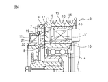
- FIG. 6 also shows a rotor 8 having a friction surface of a friction material 7 that is rotated by transmission of rotational power, and a friction surface of the rotor 8 as a reference example of such a conventional magnetic clutch.
- armature 9 having a rubbed surface
- electromagnetic coils 10 and 10 ' for generating magnetic force by energization and attracting the armature 9 to the rotor 8 side
- a hub 11 for transmitting the rotational power of the armature 9 to the compressor It is shown.
- the magnet clutch 6 is provided to interrupt the rotational driving force transmitted from an automobile engine (not shown) to a refrigerant compressor for a vehicle air conditioner, and is integrated with a pulley 12 that is rotationally driven by the engine.
- 8 is composed of electromagnetic coils 10 and 10 ′ which are frictionally engaged with each other.
- a multi-strip V belt (not shown) is wound around the pulley 12, and the rotor 8 is rotatably supported via a bearing 14 on the inner periphery thereof.
- the rotor 8 frictionally engages the armature 9 with an annular inner wall 15 positioned on the inner peripheral side of the electromagnetic coil 10, an annular outer wall 16 integrated with the pulley 12 positioned on the outer peripheral side of the electromagnetic coil 10, and the armature 9.
- the bottom wall 17 is provided with arc-shaped through holes 5 and 5 ′ that play a role of magnetic shielding.
- the arc-shaped through holes 5 and 5 ′ prevent a magnetic path from being formed directly between the inner wall 15 and the magnetic body portion 19, and between the magnetic body portion 19 and the outer wall 16.
- the frictional engagement surface between the frictional surface 20 of the armature 9 and the frictional surface 21 of the armature 9 is repeatedly passed across several times.
- the arc-shaped through hole 5 (corresponding to the arc-shaped through hole 5 in FIG.
- annular groove is formed on the outer peripheral side of the friction surface of the bottom wall 17 (corresponding to the rotor 2 in FIG. 5).
- An annular friction material 7 (corresponding to the friction material 1 in FIG. 5) is fitted in the groove to increase the engagement force with the armature 9 as shown in FIG. A layered adhesive composite is formed.
- Japanese Patent Application Laid-Open No. 7-305035 discloses that at least one of two or more parts to be bonded has resin-based adhesion. Resin-based paint in which paint is applied and the applied part and the other part are assembled in contact, and then the parts are contacted with each other by baking. A bonding method is disclosed. However, this bonding method requires further improvement because the bonding strength may be insufficient depending on the product to be obtained.
- an adhesive is applied for the purpose of adhesion between the surface of the coating film and the adherend such as a friction material after a coating containing a thermosetting resin is applied and cured in advance.
- Adhering requires a special process of applying an adhesive, and the material cost of the adhesive, the labor and time required for the process, and the increase in equipment costs, etc., and There is a problem that productivity is lowered due to management load such as adhesive application, etc.
- one part is coated with resin-based adhesive paint and the applied part is in contact with the other part. There is a problem that it is difficult to obtain the required adhesive strength only by baking after assembling.
- the present invention has been made in view of such conventional problems, and in particular, between the surface of a coating film and a friction material after a coating containing a thermosetting resin or the like is applied and cured in advance in the prior art.
- An object of the present invention is to provide an adhering method and an adhering composite capable of ensuring sufficient and sufficient adhering strength with a simpler structure than conventional methods by omitting the step of applying an adhesive and adhering both for the purpose of adhering It is what.
- the present invention may be produced by material costs such as adhesives in the prior art, labor and time required for the process, and increase in equipment costs for the process, and quality control load such as adhesive application state.
- the purpose is to prevent the deterioration of the property.
- it is difficult to obtain the required adhesive strength by simply applying a paint having adhesiveness to one component and then abutting assembly with the other component and then baking. The purpose is to solve the problem.
- the fixing method according to the first aspect of the present invention is a method for fixing an adherend (51) containing a friction material to an object to be coated (50) as described in claim 1,
- a coating film (53 ′) is formed with a curable resin-containing paint on at least a part of the surface (54) of (50), and the adherend (51) is adhered to the uncured coating film (53 ′).
- the coating film (53 ′) is cured by applying a coating film (53 ′) to heating and / or irradiation with active energy rays while pressing at a predetermined pressure, and the surface (54) of the object to be coated (54) is cured. ) To adhere the adherend (51).
- the purpose is to adhere between the surface of the coating film and the adherend after the paint containing a thermosetting resin or the like has been applied and cured in advance on the surface of the object to be coated.
- a fixing method capable of securing a sufficient and sufficient fixing strength by a simpler process than in the past by applying an adhesive and bonding the two together.
- an adhering complex is an adhering complex formed by adhering an adherend (51) containing a friction material to an object to be coated (50).
- the adherend (51) is pressed against the uncured coating film (53 ') formed of the curable resin-containing paint on at least a part of the surface (54) of the object to be coated (50) with a predetermined pressure.
- the adherend (51) is fixed to the surface (54) of the article (50) by the coating film (53) cured in a state where the adherend (51) is in close contact. It is what.
- the adherend (51) containing the friction material is applied to the coating film (53 ′) of the curable resin-containing paint formed on the surface (54) of the object (50) with a predetermined pressure.
- the curable resin-containing coating material having fluidity by melting or the like enters the gap between the object to be coated (50) and the adherend (51), and then the adherend (51) is not in contact with the adherend (51).
- the cured composite film (53 ') is cured, and the object to be coated (50) and the adherend (51) are bonded by a chemical bond or an intermolecular force, thereby being fixed with a necessary and sufficient fixing strength.
- the body is obtained.
- the press in that case is required in order to eliminate the clearance gap between the to-be-coated object and a to-be-adhered body at the time of the flow of curable resin containing coating material.
- the coating film made of the curable resin-containing coating includes the adherend (51) including the friction material. It also has a function of adhering to the object to be coated (50) with a predetermined adhering strength.
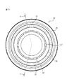
- FIG. 1 a is a plan view of a rotor of a magnet clutch which is a specific embodiment of the fixed composite in the present invention.
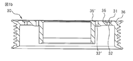
- FIG. 1b is a cross-sectional view taken along the line XX in FIG. 1a showing a rotor of a magnetic clutch which is a specific embodiment of the fixed composite in the present invention.
- FIG. 1c is an enlarged cross-sectional view of the friction material fixing portion in FIG. 1b showing a rotor of a magnet clutch which is a specific embodiment of the fixing composite in the present invention.
- FIG. 2 is an enlarged cross-sectional view of the friction material fixing portion when the surface of the object to be coated does not have a groove shape, which is an example of the fixing complex in the present invention.
- FIG. 1 a is a plan view of a rotor of a magnet clutch which is a specific embodiment of the fixed composite in the present invention.
- FIG. 1b is a cross-sectional view taken along the line XX in FIG. 1a
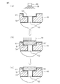
- FIG. 3 is an explanatory view schematically showing, as a processing flow, an example of a method for fixing an adherend to an object to be coated in the present invention.
- FIG. 4 is an explanatory view schematically showing an example of a method for fixing an adherend to an object to be coated in the present invention as a processing flow.
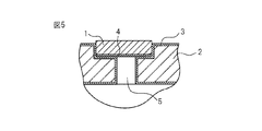
- FIG. 5 is an explanatory view schematically showing an enlarged cross-sectional view of a four-layer bonded composite for bonding a friction material in a rotor of a magnet clutch as a prior art.
- FIG. 6 is an explanatory view showing a specific example of a magnet clutch in the prior art.
- the object to be coated (50) in the present invention is not particularly limited, but specific examples of the object to be coated (50) include a clutch, a brake, an automatic transmission, a limited slip differential, a hoist, and a synchronization. Devices, torque converters, torque transmission devices, other friction type power transmission devices and power absorption devices, among others, friction type power transmission devices and power absorption devices are preferable, and friction type power transmission devices are more preferable, A magnet clutch is particularly preferable.
- a specific example of the object to be coated (50) includes a magnet clutch rotor.
- the adherend (51) including the friction material according to the present invention is, for example, a composite material including a porous material as a friction material, or a thin plate material such as a metal having good adhesion to a curable resin-containing paint. Etc. Among these, a composite material including a porous material is preferable as the adherend (51). When a member having an uneven surface, such as a composite material including such a porous material, is used as the adherend (51), the adherend (51) is pressed against and closely adhered to the coating film (53 ′).
- a composite material including a porous friction material can be advantageously used in a frictional power transmission device and a power absorption device.
- the form of the curable resin-containing paint used in the present invention is not particularly limited. Specifically, for example, a powder form, a liquid form such as an electrodeposition paint or a spray paint, and Examples include pasty ones, among which powdery ones are preferable.
- the shape and size of the powder are not particularly limited, and powders having a normal shape and size can be used.
- the particle size distribution is preferably in the range of 10 to 250 ⁇ m, particularly preferably in the range of 20 to 100 ⁇ m.
- the average particle diameter is preferably about 30 to 60 ⁇ m.
- such a powdery curable resin-containing paint can be prepared by a usual method.
- the method for forming the coating film (53 ′) with the curable resin-containing paint in the present invention is not particularly limited, but preferably the powdery curable resin-containing paint as described above is used, for example, in a fluidized bed.
- powder coating may be performed by friction charging method such as friction charging method in which electrostatic charging is performed by electrostatic charging, or electrostatic powder spraying method in which electrostatically charged powder is sprayed.
- friction charging method such as friction charging method in which electrostatic charging is performed by electrostatic charging, or electrostatic powder spraying method in which electrostatically charged powder is sprayed.
- the formed coating film (53 ′) becomes uniform, and the cured coating film (53) tends to be uniform, so that the surface (50) of the object to be coated (50) ( 54) It becomes easy to make the adherence strength of the adherend (51) to 54) uniform.
- the triboelectric powder coating by the electrostatic powder spraying method can form a uniform coating film (53 ′) on the object to be coated (50) having a complicated surface shape such as the groove-shaped portion (57). Since it becomes easy, it is preferable.
- the formation of the coating film (53 ′) with such a curable resin-containing coating is performed on at least a part of the surface (54) of the object to be coated (50). )
- the coating film (53 ') is formed on all surfaces of the surface of the object to be coated (50) that need to be improved in corrosion resistance. Is preferably made.
- the shape of the surface of the article (50) to be coated on which the coating film (53 ′) is formed is not particularly limited, and may have no groove shape. It is preferable to have a groove shape (57).
- the adherend (51) is fixed when the adherend (51) is fixed to the groove shape portion (57). Since the adherend (51) is pressed and the curable resin-containing paint flows on the side surface of the groove-shaped portion and flows into the groove without any gap, it is easy to cure, so that it is easier to obtain the fixing strength than those without the groove shape.
- the coating film (53 ') can be easily held, and eventually the surface (50) of the object to be coated (50) ( 54) It is easy to improve the adhesion strength of the adherend (51) and to stabilize the adhesion.
- the shape of the groove is not particularly limited as long as at least a part of the adherend (51) including the friction material can be inserted. However, a shape into which most of the adherend (51) can be inserted. preferable.
- a coating film (53 ') is formed on the bottom surface and both side surfaces of the groove shape portion, and the adherend includes a friction material.
- (51) is cured while being pressed against the uncured coating film (53 ′) with a predetermined pressure, so that at least the bottom surface (54) of the groove-shaped portion (57) is covered, particularly on the bottom surface (54) and both side surfaces. It is preferable to fix the adherend (51) to the object to be coated (50).
- the adherend (51) and the covering are formed on both sides as well as the bottom surface of the groove-shaped portion (57).
- the adhesion strength of the coated object (50) can be ensured, and as a result, the adhesion strength of the adherend (51) to the object to be coated (50) can be improved and the adhesion can be stabilized.
- the object to be coated in the prior art is used.
- the adherend (51) when a member having an uneven surface such as a composite material including a porous material is used as the adherend (51), the adherend (51) is pressed against and closely adhered to the coating film (53 ′).
- the uncured coating film (53 ′) is cured in the state, an anchor effect is obtained by flowing and curing the curable resin-containing paint into the concave portion, which is preferable.
- curable resin examples include a thermosetting resin and an active energy ray curable resin.
- thermosetting resin is not particularly limited. Specifically, for example, an epoxy resin, a molding compound from an unsaturated polyester resin, a DAP resin (polydiallyl phthalate), an MF molding compound, such as a curable melamine, is used.
- Thermosetting resins in the form of polycondensates such as phenol / formaldehyde molding compounds or crosslinked polyurethanes, curable phenol / formaldehyde plastics, curable bisphenol resins, curable urea / formaldehyde plastics, polyimides, bismaleimides
- Thermosetting resins in the form of polyaddition materials such as material molding compounds and polybenzimidazoles can be mentioned.
- an epoxy resin is preferable.
- the active energy ray-curable resin is not particularly limited, and examples thereof include resins having an unsaturated group in the molecular chain or in the side chain. More specifically, unsaturated polyester resin, polyester (meth) acrylate resin, epoxy (meth) acrylate resin, polyurethane (meth) acrylate resin, polyether (meth) acrylate resin, polyallyl compound, polyvinyl compound, polyacrylated silicon Examples thereof include resins and polybutadiene.
- thermosetting resin and an active energy ray curable resin may be mixed and used, but it is desirable to use either one, the ease of the curing treatment after the coating film is formed, A thermosetting resin is preferable from the viewpoint of uniformity of the obtained curing.
- composition of the curable resin-containing coating in the present invention is not particularly limited, but specifically, for example, the content of the curable resin as described above is 40 to 80% by weight, preferably 50 to 70%. In addition, other components may be contained in a desired content as required.
- the curable resin is a thermosetting resin
- a curing agent in addition to the thermosetting resin, a curing accelerator, or the like may be included as necessary.
- the type and content of such a curing agent or curing accelerator are not particularly limited, and those that are usually used may be contained at a normal content.
- a radical polymerization initiator such as a photopolymerization initiator, a filler, an additive, and the like are included as necessary in addition to the active energy ray curable resin. May be.
- the type and content of such radical polymerization initiator and the like are not particularly limited, and those usually used may be contained in a normal content.
- thermoplastic resin a charge control agent, or a charge enhancing agent, which is usually used, is used together with the curable resin as necessary. May be contained.
- the thickness of the coating film (53 ′) formed with the curable resin-containing paint in the present invention is not particularly limited.
- the thickness of 30 to 60 ⁇ m is an adherend containing a friction material ( 51) and the object to be coated (50) are effective in improving the fixing strength and stabilizing the fixing.
- the method and conditions for forming the coating film (53 ') with the curable resin-containing paint in the present invention are not particularly limited, and commonly used methods and conditions can be appropriately selected.
- a method using a fluidized bed, a fluid dipping method, an electrostatic coating method, a thermal spraying method, and the like can be given, and among these, the electrostatic coating method is preferable.
- the method and conditions for curing the coating film (53 ′) of the curable resin-containing coating formed on at least a part of the surface of the article (50) in the present invention are not particularly limited, and are usually The method and conditions used can be appropriately selected.
- the heating means is usually used such as induction heating, electromagnetic heating such as dielectric heating, heating in a thermostatic bath, resistance heating, far infrared heating, etc.
- Inductive heating is preferable when the object to be coated (50) is a conductor such as a metal such as iron, aluminum, or copper, and dielectric heating when the object to be coated (50) is a non-conductor. Is preferred.
- the heating temperature and curing time can be appropriately selected depending on the composition of the curable resin-containing paint and the thickness of the coating film, but the heating temperature is usually preferably 130 to 250 ° C.
- the curing time by heating for example, when the object to be coated (50) is a conductor such as a metal, the curing time is 1 according to induction heating, although it depends on the shape and mass of the object to be coated (50). It can be shortened within minutes.
- the curable resin is an active energy ray curable resin
- active energy ray irradiation is used.
- the active energy rays include electron beams, ultraviolet rays, and gamma rays. Irradiation conditions can be appropriately selected depending on the composition of the curable resin-containing paint and the thickness of the coating film. However, it is usually preferable to irradiate so that the integrated active energy dose is 50 to 5000 mJ / cm 2 .
- the adherend (51) including a friction material is obtained.
- the unpressed coating film (53 ′) is brought into close contact with and pressed at a predetermined pressure, and the predetermined pressure for the pressing is preferably 100 to 300 kPa. Under such pressure, the adherend (51) is cured while being pressed against the uncured coating film (53 ') of the curable resin-containing paint, so that a predetermined fixing strength can be reliably obtained.
- the predetermined fixing strength of the adherend (51) including the friction material to the surface of the object to be coated (50) according to the present invention varies depending on the type of the object to be coated (50) or the product including the object.
- the strength is preferably 12 N / mm 2 or more when the product including the object to be coated (50) is a magnet clutch rotor for an air conditioner of an automobile.
- the uncured coating film (53 ′) is cured in such a state that it is pressed at such a pressure, so that the coating material including the friction material is not required without the need for the above-described conventional bonding operation.
- the predetermined adhesion strength of the adherend (51) to the object to be coated (50) can be easily secured in a short curing time. That is, in the present invention, in the prior art, for the purpose of adhesion between the surface of the coating film and the adherend after the paint containing a thermosetting resin or the like has been applied and cured in advance on the surface of the object to be coated.
- the process of applying the adhesive and bonding them together is omitted, and the material costs for the adhesive, the labor and time required for the process, and the equipment costs for the process, as well as the quality of the adhesive application state, etc. In some cases, it is possible to prevent a decrease in productivity due to a management load or the like and to securely adhere the adherend to the object to be coated with a predetermined adhesion strength in a short time.
- an adherend (51) including a friction material, an object to be coated (50), a curable resin-containing paint, and a coating film formed from the paint ( 53 ′) means the same as in the fixing method according to the first aspect of the present invention.
- the coating film (53) cured in a state in which the adherend (51) pressed at a predetermined pressure is in close contact with the uncured coating film (53 ′) in the fixed composite body is the first aspect of the present invention. The same thing as what is obtained in the fixing method which is 1 aspect is meant.
- the coating film (53) cured in a state of being pressed at a predetermined pressure does not particularly require an adhesive layer in the prior art as described above,
- the conditions and the curing method and conditions of the coating film (53 ′) are preferably the same as those in the fixing method according to the first aspect of the present invention.
- the adhesion between the surface of the coating film and the adherend after the coating material containing a thermosetting resin or the like is previously applied and cured on the surface of the object to be coated in the prior art.
- a commonly used method may be used as a method for measuring the adhesion strength of the adherend (51) including the friction material to the surface of the object to be coated (50). Examples include a method using a thickness test, a tensile shear bond strength test, a compression shear bond strength test, a peel bond strength test, an impact bond strength test, a bending bond strength test, and a split bond strength test.
- FIG. 1a to FIG. 1c show a rotor of a magnetic clutch that is a specific example of the fixed composite in the present invention.
- a plurality of arc-shaped through holes 32 provided at predetermined intervals are provided on the bottom surface, and a ring-shaped friction material 31 having a rectangular cross-sectional shape is fitted therein, which corresponds to the fixed composite of the present invention.
- the rotor 30 with the recess 36 is shown in plan view.
- FIG. 1b as a cross-sectional view at XX in FIG. 1a, an arc-shaped through hole 32 is provided on the bottom surface, and a friction material 31 is fitted to form a friction material fixing portion corresponding to the fixing composite of the present invention.
- a cross-sectional view of the rotor 30 including the groove-shaped portion 35 and the groove-shaped portion 35 ′ having an arc-shaped through hole 32 ′ is shown.
- the rotor 30 shown in FIG. 1b is formed by fitting most of a ring-shaped friction material 31 having a rectangular cross-section into a groove-shaped portion 35 having an arc-shaped through hole 32 on the bottom surface. Further, an enlarged cross-sectional view of a friction material fixing portion corresponding to the fixing composite of the present invention is shown. That is, in FIG. 1 c, the friction material 31 is applied to the uncured coating film formed on the surface of the rotor 30 with the thermosetting resin-containing paint, and the uncured coating film on the bottom surface 34 of the groove-shaped portion 35. Shows a fixed composite of the present invention in which the friction material 31 is fixed to the bottom surface 34 of the groove-shaped portion 35 by a coating film 33 formed by being heated and cured in a state of being pressed at a predetermined pressure. Yes.
- FIG. 2 is an enlarged cross-sectional view of an example of an embodiment of the fixed composite when the surface of the object to be coated does not have a groove shape in the present invention. That is, FIG. 2 shows an uncured coating film formed of, for example, a thermosetting resin-containing paint on the surface of the rotor 40 of the magnet clutch, and an uncured coating on the upper surface 44 of the arc-shaped through hole 42.
- the fixed composite of the present invention in which the friction material 41 is fixed to the surface 44 of the rotor 40 by the coating film 43 formed by heating and curing the friction material 41 in a state where the friction material 41 is pressed at a predetermined pressure. It is shown.
- FIG. 3 schematically shows an embodiment of a method for fixing an adherend including a friction material to an object to be coated in the present invention as a processing flow using an enlarged cross-sectional view of the fixing portion. That is, in FIG. 3 (a), an object to be coated, which is a rotor of a magnet clutch as shown in FIGS. 1a to 1c, includes an arc-shaped through hole 52 on the bottom surface and includes an annularly extending groove-shaped portion 57. An uncured coating film 53 ′ is formed on the surface 50 by the powdery curable resin-containing paint 56 supplied from the powdery curable resin-containing paint supply means 55.
- thermosetting resin is contained on the bottom surface 54 and both side surfaces of the groove-shaped portion 57 of the article 50 by being heated as shown in (b) of FIG. 3.
- a simpler three-layer fixed composite including the adherend 51 fixed by the cured coating film 53 is obtained.
- FIG. 4 schematically shows an embodiment of a method for fixing an adherend including a friction material to an object to be coated in the present invention as a processing flow using an enlarged cross-sectional view of the fixing portion. That is, in FIG. 4 (a), the object 60 to be coated includes a groove-shaped portion 67 that is not provided with an arc-shaped through hole 32, which is a rotor of a magnet clutch as shown in FIGS. 1a to 1c. An uncured coating film 63 ′ is formed with the powdery curable resin-containing paint 66 supplied from the powdery curable resin-containing paint supply means 65.
- thermosetting resin is contained on the bottom surface 64 and both side surfaces of the groove-shaped portion 67 of the article 60 by being heated as shown in (b) of FIG. 4.
- a simpler three-layer fixed composite including the adherend 61 fixed by the cured coating film 63 is obtained.
- FIG. 5 shows an example related to the prior art for clarifying the comparison with the embodiment of the method of fixing the adherend of the present invention to the object to be coated shown in FIG.
- the surface of the coating film 3 and the deposition after the paint containing a thermosetting resin or the like is applied in advance to the surface of the rotor 2 having the arcuate through-hole 5 and the groove shape
- the adhesive 4 is applied for the purpose of bonding with the friction material 1 that is a body, or the adhesive sheet 4 is pasted to bond the friction material 1 to the rotor 2 of the magnet clutch.
- a layered adhesive composite is schematically shown.
- a paint containing a thermosetting resin or the like is applied to the rotor 2 of the magnet clutch, and the thermosetting resin is cured by heating to form the coating film 3.
- the adhesive 4 is applied to the cured coating film 3 or the adhesive sheet 4 is pasted, and the coating film 3 and the friction material 1 are bonded together with the friction material 1 disposed thereon.
- a four-layered adhesive composite is formed in which the friction material 1 is bonded to the rotor 2 of the magnet clutch.
- the annular friction body 51 (inner diameter: 81.9 mm), which is a porous composite material mainly composed of a fiber base material, which is an adherend including a friction material.
- a thermosetting resin (60.0% by weight) made of epoxy resin is applied to the entire surface of the rotor 50 of the magnet clutch mainly composed of iron, which is an object to be coated, from the supply means 55 which is an electrostatic powder spraying method.
- a curing agent (2.0% by weight), an additive (2.0% by weight), and a pigment (36.0% by weight), and a powdery thermosetting having an average particle size of 30 to 40 ⁇ m Resin-containing paint 56 is supplied, and powder coating is applied by the triboelectric charging method, with an almost uniform thickness of 50 ⁇ m.
- a coating film 53 ' To form a coating film 53 '.
- six arc-shaped through holes 52 for magnetic shielding are provided at equal intervals over the entire circumference on the back side of the annular groove-shaped portion 57 of the rotor 50 of the magnet clutch, that is, the bottom of the groove-shaped portion 57. It was.
- the temperature of the uncured coating film 53 ′ is set by placing the annular friction body 51 and heating the whole with heat generated by induction heating means (not shown) that is low frequency induction heating while applying a pressure 58 of 250 kPa. Was heated to about 190-240 ° C. (measured with a thermocouple (not shown)), induction heating was stopped, and the coating film 53 ′ was cured by maintaining for about 40 seconds.
- a simpler three-layer fixed composite composed of an annular friction member 51 which is an adherend fixed only by 53 was obtained.
- the fixing strength of the annular friction body 51 to the rotor 50 of the magnet clutch was provided at equal intervals over the entire circumference on the back side of the annular groove-shaped portion 57 of the rotor 50 of the magnet clutch, that is, the bottom surface of the groove-shaped portion 57.
- a rectangular flat surface jig having a tip shape of 1 mm ⁇ 5 mm was pressed and fixed to the bottom surface and both side surfaces of the annular groove-shaped portion 57 excluding the opening of the through hole.
- the annular friction body was 40 N / mm 2 that led to the destruction of the base material.
- the three-layer fixed composite fixed with such fixed strength can be used as a clutch for transmitting rotational power to a compressor for an air conditioner of an automobile.
- an annular friction body 61 (inner diameter: 81.9 mm), which is an adherend including a friction material, and is a porous composite material mainly composed of a fiber base material.
- a thermosetting resin (60.0% by weight) made of epoxy resin is applied to the entire surface of the rotor 60 of the magnet clutch mainly composed of iron, which is an object to be coated, from the supply means 65 which is an electrostatic powder spraying method.
- Resin-containing paint 66 is supplied and powder-coated by triboelectric charging method, with a nearly uniform thickness of 50 ⁇ m To form a coating film 63 '.
- the annular friction body 51 (inner diameter: 81.9 mm, outer diameter: 95), which is a porous composite material mainly composed of a fiber base material, which is an adherend including a friction material. .3 mm, width 6.7 mm, thickness 2.0 mm) to which an annular groove-shaped portion 57 having an inner diameter of 81.7 mm, an outer diameter of 95.4 mm, a width of 6.9 mm, and a depth of 1.7 mm is provided.
- an active energy ray-curable resin which is a (meth) acrylic polymer in which a photopolymerizable unsaturated group is introduced into a side chain by reacting an epoxy group of 3,4-epoxycyclohexenylmethyl acrylate with a part of the group Cycloma P (ACA) Z-251 "(manufactured by Daicel Chemical Industries, Ltd.) (60.0 wt%), photopolymerization initiator (2.0 wt%), additive (2.0 wt%), pigment (36 0.06%) and a powdery active energy ray-curable resin-containing paint 56 having an average particle size of 30 to 40 ⁇ m is supplied and powder-coated by a frictional charging method, and is substantially uniform at 50 ⁇ m
- a thick coating film 53 ′ is formed.
- six arc-shaped through holes 52 for magnetic shielding are provided at equal intervals over the entire circumference on the back side of the annular groove-shaped portion 57 in the rotor 50 of the magnet clutch, that is, the bottom of the groove-shaped portion 57. Yes.
- An ultraviolet exposure device manufactured by Oak Manufacturing Co., Ltd., model HMW-680GW, using a metal halide lamp 7 kW) (not shown) (not shown) is used with ultraviolet rays (300 to 450 nm) while placing the friction body 51 and applying a pressure 58 of 250 kPa. Is applied to the coating film 53 ′ at 400 mJ / cm 2 (about 40 seconds), and then heat-cured at 150 ° C. for 60 minutes (inside the furnace: 70 minutes) using a hot-air circulating drying furnace (not shown). Therefore, the coating film 53 ′ is cured.
- the three-layer fixed composite fixed in this manner can be used as a clutch for transmitting rotational power to a compressor for an air conditioner of an automobile.
Landscapes
- Engineering & Computer Science (AREA)
- General Engineering & Computer Science (AREA)
- Mechanical Engineering (AREA)
- Physics & Mathematics (AREA)
- Electromagnetism (AREA)
- Plasma & Fusion (AREA)
- Thermal Sciences (AREA)
- Braking Arrangements (AREA)
- Laminated Bodies (AREA)
- Paints Or Removers (AREA)
- Adhesives Or Adhesive Processes (AREA)
- Application Of Or Painting With Fluid Materials (AREA)
Priority Applications (3)
| Application Number | Priority Date | Filing Date | Title |
|---|---|---|---|
| DE112013003478.6T DE112013003478T5 (de) | 2012-07-10 | 2013-07-03 | Verfahren zum Befestigen eines Flügelteils an einem Beschichtungsgegenstand und befestigte Verbundstruktur |
| US14/413,597 US9746045B2 (en) | 2012-07-10 | 2013-07-03 | Method of fastening adherend to coating object, and fastened composite |
| CN201380035623.6A CN104411414A (zh) | 2012-07-10 | 2013-07-03 | 将附着体固定到涂布物体的方法以及固定复合体 |
Applications Claiming Priority (4)
| Application Number | Priority Date | Filing Date | Title |
|---|---|---|---|
| JP2012-154607 | 2012-07-10 | ||
| JP2012154607 | 2012-07-10 | ||
| JP2013-118976 | 2013-06-05 | ||
| JP2013118976A JP5737334B2 (ja) | 2012-07-10 | 2013-06-05 | 被着体を被塗装物に固着する方法、及び固着複合体 |
Publications (1)
| Publication Number | Publication Date |
|---|---|
| WO2014010489A1 true WO2014010489A1 (ja) | 2014-01-16 |
Family
ID=49915950
Family Applications (1)
| Application Number | Title | Priority Date | Filing Date |
|---|---|---|---|
| PCT/JP2013/068287 Ceased WO2014010489A1 (ja) | 2012-07-10 | 2013-07-03 | 被着体を被塗装物に固着する方法、及び固着複合体 |
Country Status (5)
| Country | Link |
|---|---|
| US (1) | US9746045B2 (enExample) |
| JP (1) | JP5737334B2 (enExample) |
| CN (1) | CN104411414A (enExample) |
| DE (1) | DE112013003478T5 (enExample) |
| WO (1) | WO2014010489A1 (enExample) |
Families Citing this family (1)
| Publication number | Priority date | Publication date | Assignee | Title |
|---|---|---|---|---|
| KR102359429B1 (ko) * | 2017-12-29 | 2022-02-08 | 현대자동차주식회사 | 자성체 합금 분말 함유 플라스틱 복합체, 이를 갖는 에어컨 컴프레서, 그리고 이들의 제조 방법 |
Citations (3)
| Publication number | Priority date | Publication date | Assignee | Title |
|---|---|---|---|---|
| JPS53134832A (en) * | 1977-04-27 | 1978-11-24 | Dba Sa | Method of bonding friction lining and brake shoe* and appratus therefor involving induction heater and holder |
| JPH08277516A (ja) * | 1995-02-07 | 1996-10-22 | Asahi Glass Co Ltd | 擬岩並びに擬石及びその製造方法 |
| JP2007127221A (ja) * | 2005-11-04 | 2007-05-24 | Akebono Brake Ind Co Ltd | ブレーキパッドの製造方法 |
Family Cites Families (9)
| Publication number | Priority date | Publication date | Assignee | Title |
|---|---|---|---|---|
| JP2932217B2 (ja) | 1991-03-20 | 1999-08-09 | 小倉クラッチ株式会社 | 電磁クラッチ |
| JPH07305035A (ja) | 1994-05-09 | 1995-11-21 | Daido Steel Co Ltd | 樹脂系塗料により接着した製品およびその接着方法 |
| JPH08114241A (ja) | 1994-10-14 | 1996-05-07 | Nippondenso Co Ltd | 電磁クラッチ |
| EP1045749B1 (de) | 1998-01-16 | 2003-04-16 | Neopreg AG | Verfahren zum beschichten von fasern |
| KR100712088B1 (ko) * | 2002-05-27 | 2007-05-02 | 한라공조주식회사 | 클러치 풀리의 마찰재 접착장치 및 방법 |
| JP4210904B2 (ja) | 2002-12-17 | 2009-01-21 | Dic株式会社 | 化粧板目止め兼接着用熱圧着硬化性樹脂組成物、化粧板及びその製造法 |
| JP2004278558A (ja) | 2003-03-12 | 2004-10-07 | Ntn Corp | 回転伝達装置 |
| JP2005180474A (ja) | 2003-12-16 | 2005-07-07 | Sanden Corp | 電磁クラッチのプーリ |
| JP2008075681A (ja) * | 2006-09-19 | 2008-04-03 | Denso Corp | マグネットクラッチ |
-
2013
- 2013-06-05 JP JP2013118976A patent/JP5737334B2/ja not_active Expired - Fee Related
- 2013-07-03 DE DE112013003478.6T patent/DE112013003478T5/de not_active Withdrawn
- 2013-07-03 US US14/413,597 patent/US9746045B2/en not_active Expired - Fee Related
- 2013-07-03 CN CN201380035623.6A patent/CN104411414A/zh active Pending
- 2013-07-03 WO PCT/JP2013/068287 patent/WO2014010489A1/ja not_active Ceased
Patent Citations (3)
| Publication number | Priority date | Publication date | Assignee | Title |
|---|---|---|---|---|
| JPS53134832A (en) * | 1977-04-27 | 1978-11-24 | Dba Sa | Method of bonding friction lining and brake shoe* and appratus therefor involving induction heater and holder |
| JPH08277516A (ja) * | 1995-02-07 | 1996-10-22 | Asahi Glass Co Ltd | 擬岩並びに擬石及びその製造方法 |
| JP2007127221A (ja) * | 2005-11-04 | 2007-05-24 | Akebono Brake Ind Co Ltd | ブレーキパッドの製造方法 |
Also Published As
| Publication number | Publication date |
|---|---|
| US9746045B2 (en) | 2017-08-29 |
| CN104411414A (zh) | 2015-03-11 |
| JP5737334B2 (ja) | 2015-06-17 |
| JP2014031497A (ja) | 2014-02-20 |
| DE112013003478T5 (de) | 2015-03-26 |
| US20150167766A1 (en) | 2015-06-18 |
Similar Documents
| Publication | Publication Date | Title |
|---|---|---|
| CA2181468C (en) | Bondable fastener for holding structural or functional parts on support elements | |
| KR100372372B1 (ko) | 단일성분의듀로플라스틱경화성코팅화합물 | |
| US9034132B2 (en) | Method for fixing a bearing ring on or in a component | |
| JPH0625438A (ja) | 複合摩擦要素およびその製造方法 | |
| US20180147788A1 (en) | Joining method and device for performing the joining method | |
| US5622785A (en) | Coating for a brake pad, a method of reducing brake pad noise, and a brake pad | |
| JP5737334B2 (ja) | 被着体を被塗装物に固着する方法、及び固着複合体 | |
| CN104685256B (zh) | 将摩擦衬片元件安置在摩擦衬片承载件上的方法和设备 | |
| US20050211512A1 (en) | Method for applying a shim | |
| JP2004064041A (ja) | 鉄芯の製造方法とその方法に適した装置 | |
| WO2014168738A2 (en) | Thermally curable bonding film adhesive with uniform thickness | |
| JPH0565468A (ja) | 熱硬化性接着剤 | |
| EP0415381B1 (en) | Method of manufacturing a friction member | |
| JP2000088021A (ja) | 接着方法 | |
| US3553007A (en) | Method of treating brake disks | |
| EP4502403A1 (en) | Fastening element with adhesive and methods for using and manufacturing the same | |
| KR102609424B1 (ko) | 비가교결합 상태로 접착된 마찰 라이닝을 갖는 마찰 디스크 | |
| KR20160003352A (ko) | 전자클러치 풀리의 마찰재 접착장치 및 이를 이용한 마찰재 접착방법 | |
| JPH0476081A (ja) | 構造用接着剤およびその施工方法 | |
| JPH0434875B2 (enExample) | ||
| JP4240580B2 (ja) | シーリング物品 | |
| JPS59144836A (ja) | デイスクパツド | |
| JPS60139773A (ja) | 嵌合接着方法 | |
| KR20040033941A (ko) | 클러치 풀리의 마찰재 접착 방법 및 이 방법에 의해마찰재가 접착된 클러치 풀리 | |
| JP2014031497A5 (enExample) |
Legal Events
| Date | Code | Title | Description |
|---|---|---|---|
| 121 | Ep: the epo has been informed by wipo that ep was designated in this application |
Ref document number: 13816219 Country of ref document: EP Kind code of ref document: A1 |
|
| WWE | Wipo information: entry into national phase |
Ref document number: 14413597 Country of ref document: US |
|
| WWE | Wipo information: entry into national phase |
Ref document number: 112013003478 Country of ref document: DE Ref document number: 1120130034786 Country of ref document: DE |
|
| 122 | Ep: pct application non-entry in european phase |
Ref document number: 13816219 Country of ref document: EP Kind code of ref document: A1 |