WO2014010479A1 - 光源装置 - Google Patents
光源装置 Download PDFInfo
- Publication number
- WO2014010479A1 WO2014010479A1 PCT/JP2013/068216 JP2013068216W WO2014010479A1 WO 2014010479 A1 WO2014010479 A1 WO 2014010479A1 JP 2013068216 W JP2013068216 W JP 2013068216W WO 2014010479 A1 WO2014010479 A1 WO 2014010479A1
- Authority
- WO
- WIPO (PCT)
- Prior art keywords
- light
- light source
- wavelength conversion
- conversion element
- optical member
- Prior art date
- Legal status (The legal status is an assumption and is not a legal conclusion. Google has not performed a legal analysis and makes no representation as to the accuracy of the status listed.)
- Ceased
Links
Images


Classifications
-
- H—ELECTRICITY
- H01—ELECTRIC ELEMENTS
- H01S—DEVICES USING THE PROCESS OF LIGHT AMPLIFICATION BY STIMULATED EMISSION OF RADIATION [LASER] TO AMPLIFY OR GENERATE LIGHT; DEVICES USING STIMULATED EMISSION OF ELECTROMAGNETIC RADIATION IN WAVE RANGES OTHER THAN OPTICAL
- H01S5/00—Semiconductor lasers
- H01S5/005—Optical components external to the laser cavity, specially adapted therefor, e.g. for homogenisation or merging of the beams or for manipulating laser pulses, e.g. pulse shaping
- H01S5/0087—Optical components external to the laser cavity, specially adapted therefor, e.g. for homogenisation or merging of the beams or for manipulating laser pulses, e.g. pulse shaping for illuminating phosphorescent or fluorescent materials, e.g. using optical arrangements specifically adapted for guiding or shaping laser beams illuminating these materials
-
- F—MECHANICAL ENGINEERING; LIGHTING; HEATING; WEAPONS; BLASTING
- F21—LIGHTING
- F21V—FUNCTIONAL FEATURES OR DETAILS OF LIGHTING DEVICES OR SYSTEMS THEREOF; STRUCTURAL COMBINATIONS OF LIGHTING DEVICES WITH OTHER ARTICLES, NOT OTHERWISE PROVIDED FOR
- F21V13/00—Producing particular characteristics or distribution of the light emitted by means of a combination of elements specified in two or more of main groups F21V1/00 - F21V11/00
- F21V13/02—Combinations of only two kinds of elements
- F21V13/08—Combinations of only two kinds of elements the elements being filters or photoluminescent elements and reflectors
-
- F—MECHANICAL ENGINEERING; LIGHTING; HEATING; WEAPONS; BLASTING
- F21—LIGHTING
- F21V—FUNCTIONAL FEATURES OR DETAILS OF LIGHTING DEVICES OR SYSTEMS THEREOF; STRUCTURAL COMBINATIONS OF LIGHTING DEVICES WITH OTHER ARTICLES, NOT OTHERWISE PROVIDED FOR
- F21V13/00—Producing particular characteristics or distribution of the light emitted by means of a combination of elements specified in two or more of main groups F21V1/00 - F21V11/00
- F21V13/12—Combinations of only three kinds of elements
- F21V13/14—Combinations of only three kinds of elements the elements being filters or photoluminescent elements, reflectors and refractors
-
- F—MECHANICAL ENGINEERING; LIGHTING; HEATING; WEAPONS; BLASTING
- F21—LIGHTING
- F21V—FUNCTIONAL FEATURES OR DETAILS OF LIGHTING DEVICES OR SYSTEMS THEREOF; STRUCTURAL COMBINATIONS OF LIGHTING DEVICES WITH OTHER ARTICLES, NOT OTHERWISE PROVIDED FOR
- F21V9/00—Elements for modifying spectral properties, polarisation or intensity of the light emitted, e.g. filters
- F21V9/30—Elements containing photoluminescent material distinct from or spaced from the light source
-
- G—PHYSICS
- G02—OPTICS
- G02B—OPTICAL ELEMENTS, SYSTEMS OR APPARATUS
- G02B19/00—Condensers, e.g. light collectors or similar non-imaging optics
- G02B19/0004—Condensers, e.g. light collectors or similar non-imaging optics characterised by the optical means employed
- G02B19/0028—Condensers, e.g. light collectors or similar non-imaging optics characterised by the optical means employed refractive and reflective surfaces, e.g. non-imaging catadioptric systems
-
- G—PHYSICS
- G02—OPTICS
- G02B—OPTICAL ELEMENTS, SYSTEMS OR APPARATUS
- G02B19/00—Condensers, e.g. light collectors or similar non-imaging optics
- G02B19/0033—Condensers, e.g. light collectors or similar non-imaging optics characterised by the use
- G02B19/0047—Condensers, e.g. light collectors or similar non-imaging optics characterised by the use for use with a light source
- G02B19/0061—Condensers, e.g. light collectors or similar non-imaging optics characterised by the use for use with a light source the light source comprising a LED
-
- G—PHYSICS
- G02—OPTICS
- G02B—OPTICAL ELEMENTS, SYSTEMS OR APPARATUS
- G02B21/00—Microscopes
- G02B21/06—Means for illuminating specimens
- G02B21/08—Condensers
-
- G—PHYSICS
- G02—OPTICS
- G02B—OPTICAL ELEMENTS, SYSTEMS OR APPARATUS
- G02B27/00—Optical systems or apparatus not provided for by any of the groups G02B1/00 - G02B26/00, G02B30/00
- G02B27/10—Beam splitting or combining systems
- G02B27/14—Beam splitting or combining systems operating by reflection only
- G02B27/141—Beam splitting or combining systems operating by reflection only using dichroic mirrors
-
- H—ELECTRICITY
- H01—ELECTRIC ELEMENTS
- H01S—DEVICES USING THE PROCESS OF LIGHT AMPLIFICATION BY STIMULATED EMISSION OF RADIATION [LASER] TO AMPLIFY OR GENERATE LIGHT; DEVICES USING STIMULATED EMISSION OF ELECTROMAGNETIC RADIATION IN WAVE RANGES OTHER THAN OPTICAL
- H01S5/00—Semiconductor lasers
- H01S5/40—Arrangement of two or more semiconductor lasers, not provided for in groups H01S5/02 - H01S5/30
- H01S5/4025—Array arrangements, e.g. constituted by discrete laser diodes or laser bar
-
- G—PHYSICS
- G02—OPTICS
- G02B—OPTICAL ELEMENTS, SYSTEMS OR APPARATUS
- G02B2207/00—Coding scheme for general features or characteristics of optical elements and systems of subclass G02B, but not including elements and systems which would be classified in G02B6/00 and subgroups
- G02B2207/113—Fluorescence
-
- H—ELECTRICITY
- H01—ELECTRIC ELEMENTS
- H01S—DEVICES USING THE PROCESS OF LIGHT AMPLIFICATION BY STIMULATED EMISSION OF RADIATION [LASER] TO AMPLIFY OR GENERATE LIGHT; DEVICES USING STIMULATED EMISSION OF ELECTROMAGNETIC RADIATION IN WAVE RANGES OTHER THAN OPTICAL
- H01S5/00—Semiconductor lasers
- H01S5/005—Optical components external to the laser cavity, specially adapted therefor, e.g. for homogenisation or merging of the beams or for manipulating laser pulses, e.g. pulse shaping
- H01S5/0078—Optical components external to the laser cavity, specially adapted therefor, e.g. for homogenisation or merging of the beams or for manipulating laser pulses, e.g. pulse shaping for frequency filtering
-
- H—ELECTRICITY
- H01—ELECTRIC ELEMENTS
- H01S—DEVICES USING THE PROCESS OF LIGHT AMPLIFICATION BY STIMULATED EMISSION OF RADIATION [LASER] TO AMPLIFY OR GENERATE LIGHT; DEVICES USING STIMULATED EMISSION OF ELECTROMAGNETIC RADIATION IN WAVE RANGES OTHER THAN OPTICAL
- H01S5/00—Semiconductor lasers
- H01S5/30—Structure or shape of the active region; Materials used for the active region
- H01S5/32—Structure or shape of the active region; Materials used for the active region comprising PN junctions, e.g. hetero- or double- heterostructures
- H01S5/323—Structure or shape of the active region; Materials used for the active region comprising PN junctions, e.g. hetero- or double- heterostructures in AIIIBV compounds, e.g. AlGaAs-laser, InP-based laser
- H01S5/32308—Structure or shape of the active region; Materials used for the active region comprising PN junctions, e.g. hetero- or double- heterostructures in AIIIBV compounds, e.g. AlGaAs-laser, InP-based laser emitting light at a wavelength less than 900 nm
- H01S5/32341—Structure or shape of the active region; Materials used for the active region comprising PN junctions, e.g. hetero- or double- heterostructures in AIIIBV compounds, e.g. AlGaAs-laser, InP-based laser emitting light at a wavelength less than 900 nm blue laser based on GaN or GaP
Definitions
- the present invention relates to a light source device.
- Patent Document 1 a semiconductor light source is used as a light source for a liquid crystal projector or the like (for example, see Patent Document 1).
- Patent Document 1 three types of phosphors are irradiated with excitation light output from a single semiconductor light source to generate red, green, and blue fluorescence, and the colors of the image are reproduced using these three colors of fluorescence. is doing.
- the Etendue represented by the product of the cross-sectional area of the light beam at a certain position of the optical system and the solid angle of the light beam is stored from the light source to the irradiation position.
- Patent Document 1 it is conceivable to arrange a plurality of light sources in order to improve the brightness of illumination light. In that case, the light emission area as a whole of the light source increases, and the Etendue on the light source side increases. As a result, the light amount of the light source increases as the light emitting area of the entire light source increases, but the light source side Etendue also increases and the light guide efficiency decreases. That is, all the light emitted from the light source cannot be efficiently guided to the narrow illumination area at the irradiation position, and part of the light is kicked and does not contribute to the improvement of the brightness of the illumination area.
- the present invention has been made in view of the above-described circumstances, and is a light source device that can be used in combination with a device that illuminates a narrow region such as a microscope or a liquid crystal projector and can increase the brightness of illumination light.
- the purpose is to provide.
- the present invention provides the following means.
- the present invention includes two light sources that output light in a direction facing each other along one optical axis, and the light source that is disposed between the two light sources and irradiated with the light output from these light sources.
- a first optical member that folds the light scattered toward the one light source side in the direction of the wavelength conversion element in parallel with the optical axis, and is disposed between the wavelength conversion element and the other light source; The light from the light source is transmitted, and the light scattered in the other light source among the light generated in the wavelength conversion element and the light turned back by the first optical member in a direction intersecting the optical axis. deflection To provide a light source device and a second optical member that.
- the light output from the two light sources is converted into light of a different color in the wavelength conversion element, and a part of the light scattered on the one light source side is subjected to the second optical by the first optical member. It is deflected in the direction of the member and overlapped with the other part of the light scattered on the other light source side.
- the entire light generated in the wavelength conversion element is output as illumination light from the second optical member.
- the total amount of light generated in the wavelength conversion element by the light from the two light sources is approximately twice that of when a single light source is used.
- the light collection efficiency of the generated light is limited by the Etendue of the individual light sources constituting the optical systems independent of each other, so that the entire generated light can be collected in a sufficiently narrow region.
- the said wavelength conversion element may have the fluorescent substance or quantum dot excited by the light output from the said light source.
- a first collimating optical system that is disposed between the wavelength conversion element and the first optical member, and that collimates light scattered from the wavelength conversion element toward the one light source
- a second collimating optical system that is arranged between the wavelength conversion element and the second optical member and converts the light scattered from the wavelength conversion element toward the second light source into parallel light; There may be.
- At least one of the first collimating optical system and the second collimating optical system may include a collimating lens or a rod integrator.
- a plurality of sets of the wavelength conversion element, the first collimating optical system, and the second collimating optical system are provided in series on the optical axis, and the wavelength conversion elements of each set have different colors.
- the light may be generated. By doing in this way, the light of a several color can be simultaneously generated from a several wavelength conversion element using a common light source.
- a plurality of color images are displayed with a time difference, a color breakup that is recognized by the observer as an afterimage does not occur.
- the second optical member is disposed on the opposite side of the light deflection direction by the second optical member, and is along the same optical axis as the light deflected by the second optical member.
- Another light source that outputs light may be provided, and the second optical member may transmit light output from the other light source. In this way, the brightness of the illumination light can be further increased by superimposing the light output from the other light source on the light generated by the wavelength conversion element.
- the plurality of wavelength conversion elements that are arranged in a direction along the optical axis or in a direction intersecting the optical axis and are irradiated with light from the light source and generate light of different colors May be provided.
- the light of a several color can be simultaneously generated from a several wavelength conversion element using a common light source.
- a color breakup that is recognized by the observer as an afterimage does not occur.
- a plurality of sets of the two light sources, the wavelength conversion element, the first optical member, and the second optical member are provided in parallel with a common optical axis of the light deflected by the second optical member. It may be.
- generated in each group is output in the state deflected and superimposed by the 2nd optical member.
- the brightness of illumination light can be increased by being suitably used in combination with a device that illuminates a narrow area such as a microscope or a liquid crystal projector.
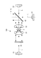
- FIG. 1 is an overall configuration diagram of a light source device according to an embodiment of the present invention. It is a whole block diagram which shows the modification of the light source device of FIG. It is a figure which shows the modification of the wavelength conversion element with which the light source device of FIG. 1 is provided. It is a figure which shows another modification of the wavelength conversion element with which the light source device of FIG. 1 is provided. It is a whole block diagram which shows another modification of the light source device of FIG. It is a whole block diagram which shows another modification of the light source device of FIG.
- the light source device 1 which concerns on one Embodiment of this invention is demonstrated with reference to drawings.
- the light source device 1 includes two light sources 21 and 22 that output beam light in a direction facing each other along one optical axis X, and a space between the light sources 21 and 22.
- the wavelength conversion element 3 that emits light when irradiated with beam light, and between the wavelength conversion element 3 and the first light source 21 and between the wavelength conversion element 3 and the second light source 22, respectively.
- Dichroic mirrors 41 and 42 and collimating optical systems 51 and 52 are provided.
- the first light source 21 and the second light source 22 are a semiconductor light source or a laser diode (LD) that outputs a monochromatic light beam with high directivity.
- the first light source 21 and the second light source 22 output light beams having the same characteristics.
- the blue laser light L having a wavelength of 450 nm is assumed as the monochromatic beam light.
- Each of the light sources 21 and 22 may be configured by arranging a plurality (for example, 2 ⁇ 2 or 3 ⁇ 3) of semiconductor light sources and LDs that output the laser light L in parallel with each other in an array. .
- the wavelength conversion element 3 is an element that emits light when irradiated with laser light L (monochromatic light) from the light sources 21 and 22, and holds, for example, a phosphor or quantum dots excited by the laser light L. .
- the wavelength conversion element 3 is a phosphor that generates the fluorescence L ′ that includes the wavelength 450 nm of the laser light L in the excitation wavelength band and has a peak wavelength of 550 nm.
- Fluorescence L ′ generated in the wavelength conversion element 3 by irradiating the laser beam L from both sides is scattered forward and backward in the traveling direction of each laser beam L.
- part of the fluorescence L1 ′ scattered toward the first light source 21 is incident on the first collimating optical system 51 and scattered toward the second light source 22 side.
- the other portion of the fluorescence L 2 ′ enters the second collimating optical system 52.
- the first dichroic mirror 41 disposed between the first light source 21 and the wavelength conversion element 3 is disposed perpendicular to the optical axis X.
- the first dichroic mirror 41 transmits the laser light L incident from the light source 21 along the optical axis X. Further, the first dichroic mirror 41 reflects a part of the fluorescence L ⁇ b> 1 ′ scattered from the wavelength conversion element 3 along the optical axis X.
- the second dichroic mirror 42 disposed between the second light source 22 and the wavelength conversion element 3 is disposed with an inclination of 45 ° with respect to the optical axis X.
- the second dichroic mirror 42 transmits the laser light L incident from the second light source 22 along the optical axis X.
- the second dichroic mirror 42 is a part of the fluorescence L2 ′ reflected from the wavelength conversion element 3 and a part of the fluorescence L2 ′ that has been reflected by the first dichroic mirror 41 and passed through the wavelength conversion element 3.
- the fluorescence L1 ′ is reflected in the direction perpendicular to the optical axis X.
- the first dichroic mirror 41 and the second dichroic mirror 42 have characteristics of transmitting light having a wavelength of 500 nm or less and reflecting light having a wavelength longer than 500 nm. .
- the first collimating optical system (first optical member) 51 is composed of, for example, a plano-convex lens (collimating lens) having a convex surface facing the first light source 21 side.
- the first collimating optical system 51 collimates the fluorescence L ⁇ b> 1 ′ incident from the wavelength conversion element 3 and emits it to the dichroic mirror 41. Further, the first collimating optical system 51 condenses the fluorescence L ⁇ b> 1 ′ reflected and returned by the dichroic mirror 41 on the wavelength conversion element 3.
- the second collimating optical system (second optical member) 52 is composed of, for example, a plano-convex lens (collimating lens) having a convex surface facing the second light source 22 side.
- the second collimating optical system 52 collimates the fluorescence L1 ′ and L2 ′ incident from the wavelength conversion element 3 and emits the light along the optical axis X.
- the first collimating optical system 51 and the second collimating optical system 52 may be composed of a combination of a plurality of lenses. Further, a rod integrator may be employed instead of the plano-convex lens.
- the blue laser light L output from the two light sources 21 and 22 is transmitted through the dichroic mirrors 41 and 42 along one optical axis X, and the wavelength conversion element 3.
- Green fluorescence L ′ is generated in the wavelength conversion element 3.
- the fluorescence L2 ′ scattered toward the second light source 22 is converted into parallel light by the second collimating optical system 52 and then deflected in a direction perpendicular to the optical axis X to be a light source device. 1 is output to the outside.
- the fluorescence L 1 ′ scattered toward the first light source 21 side is converted into parallel light by the first collimating optical system 51, folded back by the dichroic mirror 41, and wavelength-converted by the first collimating optical system 51. It is focused on.
- the fluorescence L1 'collected on the wavelength conversion element 3 hardly passes through the wavelength conversion element 3 without exciting the phosphor and causing energy loss.
- the fluorescence L1 ′ transmitted through the wavelength conversion element 3 is converted into parallel light by the second collimating optical system 52 and is perpendicular to the optical axis X, similarly to the fluorescence L2 ′ scattered toward the second light source 22 side.
- the light is deflected in any direction and output to the outside of the light source device 1. Thereby, the entire fluorescence L ′ generated in the wavelength conversion element 3 is output from the light source device 1 as final illumination light.
- the illumination light output from the light source device 1 is used as illumination light for a microscope or a projector, for example. That is, the illumination light is condensed and applied to a narrow area of an illumination object such as a microscope observation sample or a liquid crystal panel included in a liquid crystal projector.
- the fluorescence L ′ is generated from the wavelength conversion element 3 using the laser light L from the two light sources 21 and 22, the generation of the fluorescence L ′ in the wavelength conversion element 3 is generated.
- the amount is approximately twice that when using a single light source 21 or 22.
- each of the light sources 21 and 22 constitutes an optical system independent of each other while sharing the other optical elements 3, 41, 42, 51 and 52. That is, the Etendue on the light source side of each of the light sources 21 and 22 is the same as that when it is assumed that the light sources 21 and 22 are arranged independently. Therefore, the fluorescence L ′ caused by each laser beam L output from each light source 21, 22 can be condensed in a sufficiently narrow region limited by the Etendue of each light source 21, 22.
- the total luminous flux of the illumination light can be collected in a narrow area with sufficiently high efficiency, and the brightness of the illumination light that irradiates the narrow area is the same as that when the single light source 21 or 22 is used.
- the brightness of the illumination light that irradiates the narrow area is the same as that when the single light source 21 or 22 is used.
- FIG. 2 shows a configuration of a light source device 100 according to a modification including three systems of light sources 21, 22, and 23.
- the third light source 23 is disposed on the opposite side of the second dichroic mirror 42 from the direction in which the fluorescence L ′ is deflected by the second dichroic mirror 42.
- the third light source 23 includes an LED and a collimating optical system, and the light L is incident on the second dichroic mirror 42 at an angle of 45 °.
- the green fluorescence L ′ generated in the wavelength conversion element 3 and the light L from the third light source 23 are mixed is output from the light source device 100 as illumination light.
- the light L from the third light source 23 of a system different from the first light source 21 and the second light source 22 is added to the fluorescence L ′, but the light L and the fluorescence L ′ are Since the wave optics are superimposed by the dichroic mirror 42, the Etendue on the irradiation object side can be small. Therefore, the total luminous flux of the illumination light L ′ + L output from the light source device 100 can be condensed in a narrow area with sufficiently high efficiency to increase the brightness.
- each color image is an afterimage. A color break-up that is perceived by the viewer occurs.
- a mechanical drive mechanism is not required, it is possible to simultaneously generate a plurality of colors of light L ′ + L without causing a color breakup.
- the single-color fluorescence L ′ is generated using the single wavelength conversion element 3, but instead, a plurality of colors using the plurality of wavelength conversion elements 3a and 3b. It is good also as producing
- the first wavelength conversion element 3 a disposed on the first light source 21 side generates green fluorescence L ′, similar to the wavelength conversion element 3 described above.
- the second wavelength conversion element 3b includes a fluorescence having a wavelength of 450 nm of the laser light L in the excitation wavelength band and a longer wavelength than the fluorescence L ′ generated by the first wavelength conversion element 3a, for example, a peak wavelength of 650 nm. The generated phosphor is held.
- the fluorescence scattered toward the first light source 21 is folded back by the dichroic mirror 41, and then the first collimating optical system 51, the first wavelength conversion element 3a, and The light enters the second collimating optical system 52 after passing through the second wavelength conversion element 3b.
- the fluorescence scattered to the first light source 21 side of the fluorescence hardly transmits an energy loss by exciting the phosphor and passes through the wavelength conversion elements 3a and 3b. Then, the entire fluorescence generated in the first wavelength conversion element 31 and the second wavelength conversion element 32 is output from the second collimating optical system 52 as illumination light.
- the two wavelength conversion elements 3a and 3b may be arranged in a direction intersecting the optical axis X as shown in FIG.
- the adjacent surfaces of the two wavelength conversion elements 3a and 3b are arranged on the substantially optical axis X so that the laser light L is irradiated to both wavelength conversion elements 3a and 3b.
- the green fluorescence L 'and the red fluorescence can be simultaneously generated from the blue laser light L.
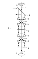
- a plurality of sets of wavelength conversion elements and collimating optical systems may be provided in series as in the light source device 200 according to the modification shown in FIG.
- a plurality of sets (two sets in the illustrated example) of wavelength conversion elements 3 and 3 are disposed on the optical axis X between the first dichroic mirror 41 and the second dichroic mirror 42.
- 'And collimating optical systems 51, 52, 51', 52 ' are provided in series.
- the wavelength conversion element 3 ′ in the subsequent stage has a longer wavelength (for example, a peak wavelength of 650 nm) than the fluorescence L ′ generated by the wavelength conversion element 3 in the previous stage. ).
- the wavelength band of the emitted light is longer as the plurality of wavelength conversion elements 3 and 3 ′ are arranged at positions away from the light source 21 on the optical axis X, that is, as they are arranged on the rear stage side. It is comprised so that a fluorescent substance may be hold
- the laser light L and the fluorescence L ′ generated by the former wavelength conversion element 3 are transmitted, and the fluorescence generated by the latter group wavelength conversion element 3 ′ is reflected.
- a dichroic mirror 43 is provided. In this way, the light source device 200 is configured such that the laser light L that has passed through the upstream wavelength conversion element 3 excites the subsequent wavelength conversion element 3 ′ to emit light.
- a third light source 23 as shown in FIG. 2 may be provided, and the wavelength conversion elements 3 and 3 ′ of each set are shown in FIGS.
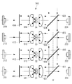
- the light sources 21 and 22, the wavelength conversion element 3, the dichroic mirrors 41 and 42, and the collimating optical systems 51 and 25 are provided as a set.
- a plurality of sets (four sets in the illustrated example) may be provided in parallel with the optical axis X ′ of the light deflected by the dichroic mirrors 421, 422, 423, and 424 in common.
- each set of the light sources 211, 212, 213, 214, 221, 222, 223, and 224 outputs the blue laser light L in the same manner as the light sources 21 and 22 described above.
- the wavelength conversion elements 31, 32, 33, and 34 generate light of different colors (for example, light blue, green, yellow, and red).
- the wavelength characteristics of the dichroic mirrors 411, 412, 413, 414, 421, 422, 423, 424 are appropriately set.
- illumination light including four colors of light can be generated.
- Each light source 211, 212, 213, 214, 221, 222, 223, 224 constitutes an optical system independent of each other. Therefore, the entire illumination light beam can be condensed in a sufficiently narrow area limited by the Etendue of each light source 211, 212, 213, 214, 221, 222, 223, 224, and the narrow area is irradiated.
- the brightness of the illumination light to be increased can be increased to about 8 times compared to that when a single light source is used.
- the light source device includes the collimating optical system.
- the configuration of the light source device is not limited to this, and the light source device may not include the collimating optical system.
Landscapes
- Physics & Mathematics (AREA)
- General Physics & Mathematics (AREA)
- Optics & Photonics (AREA)
- Electromagnetism (AREA)
- Condensed Matter Physics & Semiconductors (AREA)
- General Engineering & Computer Science (AREA)
- Engineering & Computer Science (AREA)
- Chemical & Material Sciences (AREA)
- Analytical Chemistry (AREA)
- Spectroscopy & Molecular Physics (AREA)
- Non-Portable Lighting Devices Or Systems Thereof (AREA)
- Projection Apparatus (AREA)
- Microscoopes, Condenser (AREA)
- Semiconductor Lasers (AREA)
Priority Applications (1)
| Application Number | Priority Date | Filing Date | Title |
|---|---|---|---|
| US14/562,928 US9574745B2 (en) | 2012-07-09 | 2014-12-08 | Light source apparatus |
Applications Claiming Priority (2)
| Application Number | Priority Date | Filing Date | Title |
|---|---|---|---|
| JP2012153232A JP5959342B2 (ja) | 2012-07-09 | 2012-07-09 | 光源装置 |
| JP2012-153232 | 2012-07-09 |
Related Child Applications (1)
| Application Number | Title | Priority Date | Filing Date |
|---|---|---|---|
| US14/562,928 Continuation US9574745B2 (en) | 2012-07-09 | 2014-12-08 | Light source apparatus |
Publications (1)
| Publication Number | Publication Date |
|---|---|
| WO2014010479A1 true WO2014010479A1 (ja) | 2014-01-16 |
Family
ID=49915940
Family Applications (1)
| Application Number | Title | Priority Date | Filing Date |
|---|---|---|---|
| PCT/JP2013/068216 Ceased WO2014010479A1 (ja) | 2012-07-09 | 2013-07-03 | 光源装置 |
Country Status (3)
| Country | Link |
|---|---|
| US (1) | US9574745B2 (enExample) |
| JP (1) | JP5959342B2 (enExample) |
| WO (1) | WO2014010479A1 (enExample) |
Cited By (1)
| Publication number | Priority date | Publication date | Assignee | Title |
|---|---|---|---|---|
| JP2016014855A (ja) * | 2014-07-01 | 2016-01-28 | 中強光電股▲ふん▼有限公司 | プロジェクター及びその照明装置 |
Families Citing this family (7)
| Publication number | Priority date | Publication date | Assignee | Title |
|---|---|---|---|---|
| JP6141220B2 (ja) * | 2014-03-11 | 2017-06-07 | 富士フイルム株式会社 | 内視鏡用光源装置及び内視鏡システム |
| JP6203127B2 (ja) * | 2014-06-11 | 2017-09-27 | 富士フイルム株式会社 | 内視鏡用光源装置及び内視鏡システム |
| JP6493739B2 (ja) * | 2015-02-12 | 2019-04-03 | カシオ計算機株式会社 | 光源装置及び投影装置 |
| CN106523955B (zh) | 2015-09-14 | 2019-10-11 | 中强光电股份有限公司 | 照明系统及投影装置 |
| ES2929785T3 (es) | 2016-09-30 | 2022-12-01 | Dolby Laboratories Licensing Corp | Combinación de haces para proyección resaltada |
| EP3306392B1 (en) * | 2016-10-06 | 2021-05-05 | Coretronic Corporation | Illumination system and projection apparatus |
| KR102384695B1 (ko) * | 2017-12-07 | 2022-04-08 | 한국전자통신연구원 | 반도체 레이저 다이오드 광원 패키지 |
Citations (6)
| Publication number | Priority date | Publication date | Assignee | Title |
|---|---|---|---|---|
| JP2001338502A (ja) * | 2000-05-30 | 2001-12-07 | Tokyo Seimitsu Co Ltd | 照明光学装置 |
| JP2002090877A (ja) * | 2000-09-19 | 2002-03-27 | Sanyo Electric Co Ltd | 投写型映像表示装置 |
| JP2005347263A (ja) * | 2004-06-04 | 2005-12-15 | Lumileds Lighting Us Llc | 照明装置における離間した波長変換 |
| JP2011048139A (ja) * | 2009-08-27 | 2011-03-10 | Seiko Epson Corp | プロジェクター |
| JP2012023013A (ja) * | 2010-06-18 | 2012-02-02 | Olympus Medical Systems Corp | 照明装置 |
| JP2012093692A (ja) * | 2010-09-28 | 2012-05-17 | Ushio Inc | 光照射装置および光照射方法 |
Family Cites Families (7)
| Publication number | Priority date | Publication date | Assignee | Title |
|---|---|---|---|---|
| US4710940A (en) * | 1985-10-01 | 1987-12-01 | California Institute Of Technology | Method and apparatus for efficient operation of optically pumped laser |
| US5663979A (en) * | 1995-11-22 | 1997-09-02 | Light Solutions Corporation | Fiber stub end-pumped laser |
| JP4449976B2 (ja) * | 2006-12-26 | 2010-04-14 | セイコーエプソン株式会社 | 外部共振型レーザ光源装置 |
| JP5429079B2 (ja) | 2010-06-30 | 2014-02-26 | 株式会社Jvcケンウッド | 光源装置および投射型表示装置 |
| CN102375314B (zh) * | 2010-08-09 | 2013-12-04 | 台达电子工业股份有限公司 | 光源系统及其适用的投影机 |
| CN102455512B (zh) * | 2010-10-21 | 2014-03-12 | 中强光电股份有限公司 | 照明装置及投影装置 |
| US9075299B2 (en) * | 2011-08-27 | 2015-07-07 | Appotronics Corporation Limited | Light source with wavelength conversion device and filter plate |
-
2012
- 2012-07-09 JP JP2012153232A patent/JP5959342B2/ja not_active Expired - Fee Related
-
2013
- 2013-07-03 WO PCT/JP2013/068216 patent/WO2014010479A1/ja not_active Ceased
-
2014
- 2014-12-08 US US14/562,928 patent/US9574745B2/en not_active Expired - Fee Related
Patent Citations (6)
| Publication number | Priority date | Publication date | Assignee | Title |
|---|---|---|---|---|
| JP2001338502A (ja) * | 2000-05-30 | 2001-12-07 | Tokyo Seimitsu Co Ltd | 照明光学装置 |
| JP2002090877A (ja) * | 2000-09-19 | 2002-03-27 | Sanyo Electric Co Ltd | 投写型映像表示装置 |
| JP2005347263A (ja) * | 2004-06-04 | 2005-12-15 | Lumileds Lighting Us Llc | 照明装置における離間した波長変換 |
| JP2011048139A (ja) * | 2009-08-27 | 2011-03-10 | Seiko Epson Corp | プロジェクター |
| JP2012023013A (ja) * | 2010-06-18 | 2012-02-02 | Olympus Medical Systems Corp | 照明装置 |
| JP2012093692A (ja) * | 2010-09-28 | 2012-05-17 | Ushio Inc | 光照射装置および光照射方法 |
Cited By (2)
| Publication number | Priority date | Publication date | Assignee | Title |
|---|---|---|---|---|
| JP2016014855A (ja) * | 2014-07-01 | 2016-01-28 | 中強光電股▲ふん▼有限公司 | プロジェクター及びその照明装置 |
| US10379431B2 (en) | 2014-07-01 | 2019-08-13 | Coretronic Corporation | Projection apparatus and illumination system having wavelength conversion modules |
Also Published As
| Publication number | Publication date |
|---|---|
| US9574745B2 (en) | 2017-02-21 |
| JP2014016438A (ja) | 2014-01-30 |
| US20150146409A1 (en) | 2015-05-28 |
| JP5959342B2 (ja) | 2016-08-02 |
Similar Documents
| Publication | Publication Date | Title |
|---|---|---|
| JP5959342B2 (ja) | 光源装置 | |
| JP5527058B2 (ja) | 光源装置及びプロジェクター | |
| JP6215989B2 (ja) | 照明システム及び投影装置 | |
| JP6292523B2 (ja) | 波長変換デバイス、照明光学系およびこれを用いた電子装置 | |
| CN105431776B (zh) | 具有发光材料轮和激发辐射源的照明装置 | |
| JP5659741B2 (ja) | 光源装置及びプロジェクター | |
| US8678596B2 (en) | Illumination device and projector with fluorescent plate | |
| CN104238248B (zh) | 光源模块与投影装置 | |
| CN102455512B (zh) | 照明装置及投影装置 | |
| CN103189794A (zh) | 照明设备以及使用其的投影型显示设备 | |
| WO2014068742A1 (ja) | 光源装置及び投写型映像表示装置 | |
| JP2020101711A (ja) | プロジェクター | |
| WO2014196079A1 (ja) | 光源装置およびそれを備えた投写型表示装置 | |
| JP2012189938A (ja) | 光源装置及びプロジェクター | |
| JP2012013977A (ja) | 光源装置及びプロジェクター | |
| JP2015040892A (ja) | 光源装置およびプロジェクター | |
| JP2012079622A (ja) | 光源装置及びプロジェクター | |
| JP2017215570A (ja) | 光源装置およびプロジェクター | |
| CN110297384B (zh) | 一种用于投影的光源 | |
| CN202443241U (zh) | 光源系统及投影系统 | |
| JP5541175B2 (ja) | 蛍光物質を用いた光源装置 | |
| WO2020031750A1 (ja) | 光源装置、およびプロジェクタ | |
| US20150138753A1 (en) | Light-source apparatus | |
| JP7188161B2 (ja) | プロジェクター | |
| JP2012094439A (ja) | 照明装置および投影型映像表示装置 |
Legal Events
| Date | Code | Title | Description |
|---|---|---|---|
| 121 | Ep: the epo has been informed by wipo that ep was designated in this application |
Ref document number: 13816937 Country of ref document: EP Kind code of ref document: A1 |
|
| NENP | Non-entry into the national phase |
Ref country code: DE |
|
| 122 | Ep: pct application non-entry in european phase |
Ref document number: 13816937 Country of ref document: EP Kind code of ref document: A1 |