EP3306392B1 - Illumination system and projection apparatus - Google Patents
Illumination system and projection apparatus Download PDFInfo
- Publication number
- EP3306392B1 EP3306392B1 EP16192627.4A EP16192627A EP3306392B1 EP 3306392 B1 EP3306392 B1 EP 3306392B1 EP 16192627 A EP16192627 A EP 16192627A EP 3306392 B1 EP3306392 B1 EP 3306392B1
- Authority
- EP
- European Patent Office
- Prior art keywords
- light source
- excitation
- wavelength conversion
- dichroic element
- disposed
- Prior art date
- Legal status (The legal status is an assumption and is not a legal conclusion. Google has not performed a legal analysis and makes no representation as to the accuracy of the status listed.)
- Active
Links
- 238000005286 illumination Methods 0.000 title claims description 76
- 230000005284 excitation Effects 0.000 claims description 237
- 238000006243 chemical reaction Methods 0.000 claims description 159
- 230000003287 optical effect Effects 0.000 claims description 24
- 230000005540 biological transmission Effects 0.000 claims description 14
- 241001507928 Aria Species 0.000 claims description 6
- 235000004494 Sorbus aria Nutrition 0.000 claims description 6
- 239000010410 layer Substances 0.000 description 46
- 239000000463 material Substances 0.000 description 16
- OAICVXFJPJFONN-UHFFFAOYSA-N Phosphorus Chemical compound [P] OAICVXFJPJFONN-UHFFFAOYSA-N 0.000 description 13
- 230000005855 radiation Effects 0.000 description 11
- 239000003086 colorant Substances 0.000 description 6
- 238000012986 modification Methods 0.000 description 2
- 230000004048 modification Effects 0.000 description 2
- 239000000843 powder Substances 0.000 description 2
- 239000011241 protective layer Substances 0.000 description 2
- 239000011347 resin Substances 0.000 description 2
- 229920005989 resin Polymers 0.000 description 2
- 239000012780 transparent material Substances 0.000 description 2
- XUIMIQQOPSSXEZ-UHFFFAOYSA-N Silicon Chemical compound [Si] XUIMIQQOPSSXEZ-UHFFFAOYSA-N 0.000 description 1
- 238000013459 approach Methods 0.000 description 1
- 230000000712 assembly Effects 0.000 description 1
- 238000000429 assembly Methods 0.000 description 1
- 230000008878 coupling Effects 0.000 description 1
- 238000010168 coupling process Methods 0.000 description 1
- 238000005859 coupling reaction Methods 0.000 description 1
- 230000007423 decrease Effects 0.000 description 1
- 230000001419 dependent effect Effects 0.000 description 1
- 238000005516 engineering process Methods 0.000 description 1
- 239000004973 liquid crystal related substance Substances 0.000 description 1
- QSHDDOUJBYECFT-UHFFFAOYSA-N mercury Chemical compound [Hg] QSHDDOUJBYECFT-UHFFFAOYSA-N 0.000 description 1
- 229910052753 mercury Inorganic materials 0.000 description 1
- 239000000203 mixture Substances 0.000 description 1
- 238000004064 recycling Methods 0.000 description 1
- 229920006395 saturated elastomer Polymers 0.000 description 1
- 229910052710 silicon Inorganic materials 0.000 description 1
- 239000010703 silicon Substances 0.000 description 1
- 229910052724 xenon Inorganic materials 0.000 description 1
- FHNFHKCVQCLJFQ-UHFFFAOYSA-N xenon atom Chemical compound [Xe] FHNFHKCVQCLJFQ-UHFFFAOYSA-N 0.000 description 1
Images


Classifications
-
- G—PHYSICS
- G03—PHOTOGRAPHY; CINEMATOGRAPHY; ANALOGOUS TECHNIQUES USING WAVES OTHER THAN OPTICAL WAVES; ELECTROGRAPHY; HOLOGRAPHY
- G03B—APPARATUS OR ARRANGEMENTS FOR TAKING PHOTOGRAPHS OR FOR PROJECTING OR VIEWING THEM; APPARATUS OR ARRANGEMENTS EMPLOYING ANALOGOUS TECHNIQUES USING WAVES OTHER THAN OPTICAL WAVES; ACCESSORIES THEREFOR
- G03B21/00—Projectors or projection-type viewers; Accessories therefor
- G03B21/14—Details
- G03B21/20—Lamp housings
- G03B21/2006—Lamp housings characterised by the light source
- G03B21/2033—LED or laser light sources
- G03B21/204—LED or laser light sources using secondary light emission, e.g. luminescence or fluorescence
-
- G—PHYSICS
- G03—PHOTOGRAPHY; CINEMATOGRAPHY; ANALOGOUS TECHNIQUES USING WAVES OTHER THAN OPTICAL WAVES; ELECTROGRAPHY; HOLOGRAPHY
- G03B—APPARATUS OR ARRANGEMENTS FOR TAKING PHOTOGRAPHS OR FOR PROJECTING OR VIEWING THEM; APPARATUS OR ARRANGEMENTS EMPLOYING ANALOGOUS TECHNIQUES USING WAVES OTHER THAN OPTICAL WAVES; ACCESSORIES THEREFOR
- G03B21/00—Projectors or projection-type viewers; Accessories therefor
- G03B21/14—Details
- G03B21/20—Lamp housings
- G03B21/2006—Lamp housings characterised by the light source
- G03B21/2013—Plural light sources
Definitions
- the invention relates to an illumination system, and more particularly to an illumination system and a projection apparatus equipped with the illumination system having a wavelength conversion element.
- a radiation generating apparatus comprising a first radiation generating source for generating radiation comprising a first range of wavelengths, a second radiation generating source for generating radiation comprising a second range of wavelengths and a photoluminescent material which is arranged to absorb radiation in the first and second wavelength range and generate radiation comprising a third range of wavelengths.
- the material comprises a first facet which is arranged to receive radiation from the first radiation source from a first direction and a second facet which is arranged to receive radiation from the second radiation source from a second direction.
- the first and second directions are substantially collinear, but opposing directions to provide for an increased illumination of the material across the same area of the material.
- an illumination apparatus including a first light emitting device, a first phosphor layer, a second light emitting device and a second phosphor layer and a beam combining element.
- the first light emitting device is capable of providing a first light beam and the first phosphor layer is disposed on the transmission path of the first light beam.
- the second light emitting device is disposed opposite to the first light emitting device and for providing a second light beam, wherein the second phosphor layer is disposed on the transmission path of the second light beam.
- the beam combining element is disposed between the first phosphor layer and the second phosphor layer.
- the invention also provides a projection apparatus.
- US 2015/146409 A1 provides a light source apparatus including first and second light sources that output light in mutually opposing directions along a single optical axis; a wavelength conversion element that is disposed between these light sources and that generates light of a wavelength different from that of said light due to irradiation with the light; a first optical member that is disposed between the wavelength conversion element and the first light source, that transmits the light therefrom, and that reflects back light that is scattered towards the first light source, toward the wavelength conversion element; and a second optical member that is disposed between the wavelength conversion element and the second light source, that transmits the light therefrom, and that deflects, in a direction intersecting the optical axis, the light scattered toward the second light source and the light reflected back by the first optical member.
- EP 1 605 199 A2 proposes an illumination device using a wavelength converting element, such as a phosphor layer, that is physically separated from a light source, such as one or more light emitting diodes, a Xenon lamp or a Mercury lamp.
- the wavelength converting element is optically separated from the light source, so that the converted light emitted by the wavelength converting element is prevented from being incident on the light source. Accordingly, the temperature limitations of the wavelength converting element are removed, thereby permitting the light source to be driven with an increased current to produce a higher radiance.
- the conversion and recycling efficiency of the device is improved, which also increases radiance.
- the projector with the solid-state light source has the following three types of light source systems: lasers, light emitting diodes (LEDs), and a combination of laser and light emitting diodes.
- Laser light source system usually uses blue laser with fluorescence wheel or phosphor wheel, and the fluorescent wheel contains phosphor layer for exciting red beam or phosphor layer for exciting green beam.
- LED light source system usually comprises a light emitting diode module for emitting red light, a light emitting diode module for emitting green light and a light emitting diode module for emitting blue light.
- the light source system with a combination of laser and light emitting diodes usually uses blue laser with fluorescence wheel, wherein the fluorescent wheel contains phosphor for exciting red beam or phosphor for exciting green beam, and the beam with the rest colors are emitted by light emitting diode or laser with specified wavelengths.
- the existing technology uses dichroic mirror to combine the red, green and blue beams provided by the respective light source modules.
- dichroic mirror due to the physical limitation of the dichroic mirror, only one of the red, green or blue light source modules is selected to use. Therefore, when the brightness of image display needs to enhance, either the power of each light source module or the quantity of laser or light emitting diodes in each light source module is required to increase.
- the aforementioned approaches may lead to the following problems: (1) the photoelectric conversion efficiency decreases if simply increasing the power of the light source module, further, the increase in power may disproportionate to the increase in the brightness and the brightness may be saturated; and therefore, the brightness may not be enhanced by indefinitely increasing the power; (2) the component size of the light source system may increase and the entire volume of the light source system may become large if simply increasing the quantity of laser or light emitting diodes; (3) the etendue may increase if simply increasing the quantity of laser or light emitting diodes, and the brightness may not be able to enhance any longer by increasing the quantity of laser or light emitting diodes if the etendue has a mismatch with the designing configuration of the projector or the etendue reaches to the maximum.
- One object of the invention is to provide an illumination system able to enhance the optical power of the beam provided by the illumination system.
- Another object of the invention is to provide an illumination system including three light source assemblies with various colors, and the illumination system has enhanced optical power of the beam provided by the illumination system.
- Still another object of the invention is to provide an illumination system having enhanced optical power of the wavelength conversion beam without increasing the light etendue; and consequentially, a projection apparatus using the illumination system has enhanced brightness of the images projected onto a screen.
- the invention provides a projection apparatus according to the independent claim.
- Advantageous embodiments are described in the dependent claims. It is proposed a projection apparatus comprising a first light source assembly.
- the first light source assembly comprises a first excitation light source, a second excitation light source, a first dichroic element, a first wavelength conversion element, a first collimating element and a second collimating element.
- the first excitation light source is configured to provide a first excitation beam.
- the second excitation light source is configured to provide a second excitation beam.
- the first excitation beam and the second excitation beam have the same color.
- the first dichroic element is disposed between the first excitation light source and the second excitation light source.
- the second excitation beam is transmitted toward the first excitation light source through the first dichroic element.
- the first wavelength conversion element is disposed between the first excitation light source and the first dichroic element.
- the first wavelength conversion element is configured to convert the first excitation beam and the second excitation beam into a first wavelength conversion beam and transmit the first wavelength conversion beam toward the first dichroic element.
- the first collimating element is disposed between the first wavelength conversion element and the first dichroic element.
- the second collimating element is disposed between the second excitation light source and the first dichroic element.
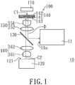
- FIG. 1 is a schematic view of an illumination system in accordance with an embodiment of the invention.
- the illumination system 10 of the embodiment includes a light source assembly 100.
- the light source assembly 100 includes a first excitation light source 110, a second excitation light source 120, a dichroic element 130, a wavelength conversion element 140, a first collimating element 150 and a second collimating element 160.
- the first excitation light source 110 is configured to provide a first excitation beam C1;
- the second excitation light source 120 is configured to provide a second excitation beam C2; and the first excitation beam C1 and the second excitation beam C2 have the same color, such as blue, for example.
- the wavelengths of the first excitation beam C1 and the second excitation beam C2 may be located within a certain range, for example, located within in a range 450 ⁇ 475 nm if the two beams are blue.
- the dichroic element 130 is disposed between the first excitation light source 110 and the second excitation light source 120.
- the dichroic element 130 is a dichroic mirror, through which the second excitation beam C2 is transmitted toward the first excitation light source 110.
- the wavelength conversion element 140 is disposed between the first excitation light source 110 and the dichroic element 130.
- the wavelength conversion element 140 is configured to convert the first excitation beam C1 and the second excitation beam C2 into a wavelength conversion beam D and transmit the wavelength conversion beam D toward the dichroic element 130.
- the first collimating element 150 is disposed between the wavelength conversion element 140 and the dichroic element 130.
- the second collimating element 160 is disposed between the second excitation light source 120 and the dichroic element 130.
- the wavelength conversion element 140 and the first excitation light source 110 are two separated elements and have a preset distance apart from each other; wherein the preset distance is not greater than the distance between the wavelength conversion element 140 and the dichroic element 130.
- the first excitation light source 110 may be a light emitting diode, a laser light source or other suitable light source.
- the second excitation light source 120 may be a light emitting diode, a laser light source or other suitable source.
- a first excitation light source 110 may be a light emitting diode chip or a laser diode chip. The structures of the first excitation light source 110 and the second excitation light source 120 may be the same or not.
- the wavelength conversion element 140 has a wavelength conversion material layer 141 and a dichroic layer 142.
- the dichroic layer 142 is disposed on the wavelength conversion material layer 141 and adjacent to the first excitation light source 110. In other words, the dichroic layer 142 is disposed between the wavelength conversion material layer 141 and the first excitation light source 110.
- the wavelength conversion material layer 141 includes wavelength conversion material such as fluorescent powder or phosphor powder, but the invention is not limited thereto.
- the surfaces of the wavelength conversion material layer 141 are configured to absorb the first excitation beam C1 and the second excitation beam C2, and the wavelength conversion material layer 141 emits the wavelength conversion beam D to the dichroic element 130.
- the first excitation beam C1 may pass through the dichroic layer 142 and then is transmitted to the wavelength conversion material layer 141.
- the wavelength conversion beam D emitted from the wavelength conversion material may be transmitted toward various directions; that is, a portion of the wavelength conversion beam D is transmitted toward the dichroic element 130 and a portion of the wavelength conversion beam D is transmitted toward the dichroic layer 142. Therefore, by using the dichroic layer 142 to reflect the wavelength conversion beam D transmitting toward the dichroic layer 142 so as to direct the wavelength conversion beam D to transmit toward the dichroic element 130, the total optical output of the wavelength conversion beam D transmitting to the dichroic element 130 is increased.
- the first excitation light source 110 and the second excitation light source 120 are disposed on the two sides of the dichroic element 130, respectively.
- the second excitation beam C2 may pass through the dichroic element 130 and the wavelength conversion beam D may be reflected by the dichroic element 130. After passing through the dichroic element 130, the second excitation beam C2 is transmitted to one side of the wavelength conversion material layer 141 facing the dichroic element 130. After passing through the dichroic layer 142, the first excitation beam C1 is transmitted to one side of the wavelength conversion material layer 141 facing the dichroic layer 142.
- the output of the wavelength conversion beam D is enhanced without increasing the light etendue.
- the first collimating element 150 and the second collimating element 160 may have the same configuration.
- the first collimating element 150 includes a collimating lens 151 and a lens 152.
- the lens 152 is disposed between the collimating lens 151 and the dichroic element 130.
- the second collimating element 160 includes a collimating lens 161 and a lens 162.
- the lens 162 is disposed between the collimating lens 161 and the dichroic element 130.
- the collimating lenses 151, 161 have the same shape and the lenses 152, 162 have the same shape.
- the specified configurations of the first collimating element 150 and the second collimating element 160 as well as the quantities of the collimating lens and lens therein are not limited in the invention. Namely, a designer may provide collimating lens and lens with different structures and quantities in response to actual requirements. Further, the optical distance of the second excitation beam C2 from the second excitation light source 120 to the dichroic element 130 is equal to the optical distance of the wavelength conversion beam D from the wavelength conversion element 140 to the dichroic element 130.
- the facula of the second excitation beam C2 on the wavelength conversion element 140 is similar to that of the second excitation beam C2 on the light-exiting surface 121 of the second excitation light source 120.
- the shape and area size of the light-exiting surface 121 of the second excitation light source 120 are same as those of the light-exiting surface 143 of the wavelength conversion element 140, respectively. Therefore, the second excitation beam C2 may substantially cover the entire wavelength conversion element 140, thereby improving light utilization and avoiding light losses.
- the color configuration of the first excitation beam C1, the second excitation beam C2 and the wavelength conversion beam D may be determined according to actual requirements.
- the color configuration may be selected from one of: (1) both of the first excitation beam C1 and the second excitation beam C2 are blue light, and the wavelength conversion beam D is green light; (2) both of the first excitation beam C1 and the second excitation beam C2 are blue light, and the wavelength conversion beam D is red light; (3) both of the first excitation beam C1 and the second excitation beam C2 are blue light, and the wavelength conversion beam D is yellow light; and (4) both of the first excitation beam C1 and the second excitation beam C2 are ultraviolet light, and the wavelength conversion beam D is white light.
- the illumination system 10 of the embodiment may further include other optical element(s), which is disposed on the transmission path of the wavelength conversion beam D after passing through the dichroic element 130.
- the optical element may include a light equalizing element (e.g., light integral rod or lens array), a lens or a mirror, and the quantity of the aforementioned optical element may be one or more than one.
- FIG. 1 is exemplified by having a light integral rod 11, to which the wavelength conversion beam D is transmitted via the dichroic element 130.
- the ratio of the area size of the light-entering end 11a of the light integral rod 11 to the area size of the light-exiting surface 143 of the wavelength conversion element 140 is ranged from 0.9 to 1.1.
- the shape of the light-entering end 11a is similar to that of the light-exiting surface 143; therefore, the wavelength conversion beam D may be received completely.
- the wavelength conversion element 140 and the first excitation light source 110 are two separated elements.
- the wavelength conversion element may be attached to the first excitation light source.
- the first light excitation light source may be the light emitting diode chip or the laser diode chip.
- the first light excitation light source and the wavelength conversion element are packaged together by the transparent resin or other transparent material (not shown).
- This embodiment is the wavelength conversion element disposed between the first excitation light source and the dichroic element.
- the wavelength conversion element may be attached the first excitation light source, and then adds a transparent protective layer above so as to protect the wavelength conversion element (not shown).
- FIG. 2 is a schematic cross-sectional view of an element integrated by the wavelength conversion element and the first excitation light source in accordance with an embodiment of the invention.
- the element includes a conductive carrier 610, a reflective layer 620, a hole-transmission layer 630, a light-emitting layer 640, an electron transmission layer 650 and a wavelength conversion layer 660.
- the layers are sequentially stacked, wherein the positions of the hole-transmission layer 630 and the electron transmission layer 650 are interchangeable.
- the electrical holes and electrons respectively provided by the hole-transmission layer 630 and the electron transmission layer 650 are combined in the light-emitting layer 640 to generate photons, and accordingly the light 641 is formed and emitted out from the light-emitting layer 640.
- a portion of the light 641 from the light emitting layer 640 transmitting toward the reflective layer 620 is reflected to the wavelength conversion layer 660, and the portion of light 641 emitting toward the wavelength conversion layer 660 is defined as the first excitation beam C1.
- the wavelength conversion layer 660 then converts the first excitation beam C1 into the wavelength conversion beam D and a portion of the wavelength conversion beam D transmitting toward the reflective layer 620 is reflected and then emitted out the element through the wavelength conversion layer 660.
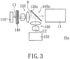
- FIG. 3 is a schematic view of an illumination system in accordance with another embodiment of the invention.
- the illumination system 10a of the embodiment is similar to the illumination system 10 of FIG. 1 , and only the difference between the two is described in the following.
- the first excitation light source 110 and the second excitation light source 120 of the light source assembly 100a are disposed on the same side of the dichroic element 130a.
- the second excitation beam C2 may be reflected by the dichroic element 130a and the wavelength conversion beam D may pass through the dichroic element 130a.
- FIG. 4 is a schematic view of an illumination system in accordance with another embodiment of the invention.
- the illumination system 10b of the embodiment is similar to the illumination system 10 of FIG. 1 , and only the difference between the two is described in the following.
- the illumination system 10b of the embodiment further includes a color wheel 12.
- the color wheel 12 is disposed on the transmission path of the wavelength conversion beam D reflected by the dichroic element 130.
- the first excitation beam C1 and the second excitation beam C2 respectively provided by the first excitation light source 110 and the second excitation light source 120 are ultraviolet light
- the wavelength conversion beam D emitted from the wavelength conversion element 140 is white light.
- the wavelength conversion beam D may be sequentially filtered into beams with various colors, such as red beam R, green beam G and blue beam B, which are transmitted to the light integral rod 11 in timing. It is to be noted that the colors of the beams filtered by the color wheel 12 and the generating sequence of the beams with various colors are not limited in the invention.
- FIG. 5 is a schematic view of an illumination system in accordance with another embodiment of the invention.
- the illumination system 10c of the embodiment is similar to the illumination system 10b of FIG. 4 , and only the difference between the two is described in the following.
- the first excitation light source 110 and the second excitation light source 120 of the light source assembly 100a are disposed on the same side of the dichroic element 130a.
- the second excitation beam C2 may be reflected by the dichroic element 130a; and the wavelength conversion beam D may pass through the dichroic element 130a and then is transmitted to the color wheel 12.
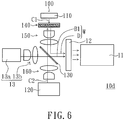
- FIG. 6 is a schematic view of an illumination system in accordance with another embodiment of the invention.
- the illumination system 10d of the embodiment is similar to the illumination system 10b of FIG. 4 , and only the difference between the two is described in the following.
- the first excitation beam C1 and the second excitation beam C2 respectively provided by the first excitation light source 110 and the second excitation light source 120 are blue light
- the wavelength conversion beam D emitted from the wavelength conversion element 140 is yellow light.
- the illumination system 10d further includes a blue light source assembly 13.
- the blue light source assembly 13 and the second excitation light source 120 are disposed on the same side of the dichroic element 130.
- the blue light source assembly 13 is configured to provide a blue beam B1.
- the blue beam B1 passes through the dichroic element 130 and is combined with wavelength conversion beam D to form a white beam W.
- the white beam W is then transmitted to the color wheel 12.
- the blue light source assembly 13 includes a blue light source 13a and a collimating element 13b.
- the blue light source 13a may be a blue light emitting diode, a laser light source, or other suitable light source.
- the collimating element 13b may have a structure same as those of the first collimating element 150 and the second collimating element 160, for example.
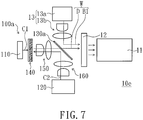
- FIG. 7 is a schematic view of an illumination system in accordance with another embodiment of the invention.
- the illumination system 10e of the embodiment is similar to the illumination system 10d of FIG. 6 , and only the difference between the two is described in the following.
- the first excitation light source 110 and the second excitation light source 120 of the light source assembly 100a are disposed on the same side of the dichroic element 130a.
- the second excitation beam C2 may be reflected by the dichroic element 130a; and the wavelength conversion beam D may pass through the dichroic element 130a and then is transmitted to the color wheel 12.
- the blue light source assembly 13 and the second excitation light source 120 are disposed on the two sides of the dichroic element 130a.
- the blue light source assembly 13 is configured to provide the blue beam B1 to the dichroic element 130a.
- the blue beam B1 may be reflected by the dichroic element 130 and then combined with the wavelength conversion beam D to form a white beam W.
- the white beam W is then transmitted to the color wheel 12.
- Each one of the illumination systems 10 ⁇ 10e of the above embodiments has one light source assembly 100 or 100a.
- the illumination system may include more than one light source assembly having a structure same as that of the light source assembly 100 or 100a.
- FIG. 8 is a schematic view of an illumination system in accordance with another embodiment of the invention.
- the illumination system 20 of the embodiment includes a first light source assembly 200 configured to provided a first color beam L1, a second light source assembly 300 configured to provided a second color beam L2, and a third light source assembly 400 configured to provided a third color beam L3; wherein the first color beam L1, the second color beam L2 and the third color beam L3 may be integrated as an illumination beam L4.
- the first light source assembly 200 includes a first excitation light source 210, a second excitation light source 220, a first dichroic element 230 and a first wavelength conversion element 240.
- the first excitation light source 210 is configured to provide a first excitation beam C1; the second excitation light source 220 is configured to provide a second excitation beam C2; and the first excitation beam C1 and the second excitation beam C2 have the same color.
- the first dichroic element 230 is disposed between the first excitation light source 210 and the second excitation light source 220.
- the second excitation beam C2 is transmitted toward the first excitation light source 210 via the first dichroic element 230.
- the first wavelength conversion element 240 is disposed between the first excitation light source 210 and the first dichroic element 230.
- the first wavelength conversion element 240 is configured to convert the first excitation beam C1 and the second excitation beam C2 into a first wavelength conversion beam and transmit the first wavelength conversion beam toward the first dichroic element 230; wherein the first wavelength conversion beam is defined as the aforementioned first color beam L1.
- the second light source assembly 300 includes a third excitation light source 310, a fourth excitation light source 320, a second dichroic element 330 and a second wavelength conversion element 340.
- the third excitation light source 310 is configured to provide a third excitation beam C3;
- the fourth excitation light source 320 is configured to provide a fourth excitation beam C4; and
- the third excitation beam C3 and the fourth excitation beam C4 have the same color.
- the second dichroic element 330 is disposed between the third excitation light source 310 and the fourth excitation light source 320.
- the fourth excitation beam C4 is transmitted toward the third excitation light source 310 via the second dichroic element 330.
- the second wavelength conversion element 340 is disposed between the third excitation light source 310 and the second dichroic element 330.
- the second wavelength conversion element 340 is configured to convert the third excitation beam C3 and the fourth excitation beam C4 into a second wavelength conversion beam and transmit the second wavelength conversion beam toward the second dichroic element 330; wherein the second wavelength conversion beam is defined as the aforementioned second color beam L2.
- the third light source assembly 400 includes a light source 410 configured to provide the third color beam L3.
- the light source 410 may be a light emitting diode, a laser light source, or other suitable light source.
- the third light source assembly 400 may further include a collimating element 420, which is disposed on the transmission path of the third color beam L3.
- the first light source assembly 200 and the second light source assembly 300 have a configuration similar to that of the light source assembly 100.
- the first wavelength conversion element 240 and the second wavelength conversion element 340 have a structure same as that of the wavelength conversion element 140.
- the first wavelength conversion element 240 and the second wavelength conversion element 340 may cover the first excitation light source 210 and the third excitation light source 310, respectively.
- the first wavelength conversion element and the first excitation light source may be integrated as an element similar to that shown in FIG. 2 ; and the second wavelength conversion element and the third excitation light source may be integrated as an element similar to that shown in FIG. 2 .
- first excitation light source 210, the second excitation light source 220, the third excitation light source 310 and the fourth excitation light source 320 each may be a light emitting diode, a laser light source, or other suitable light source.
- first light source assembly 200 may further include a first collimating element 250, which is disposed between the first wavelength conversion element 240 and the first dichroic element 230, and a second collimating element 260, which is disposed between the second wavelength conversion element 220 and the first dichroic element 230.
- the second light source assembly 300 may further include a third collimating element 350, which is disposed between the second wavelength conversion element 340 and the second dichroic element 330, and a fourth collimating element 360, which is disposed between the fourth wavelength conversion element 320 and the second dichroic element 330.
- the second dichroic element 330 is disposed between the first dichroic element 230 and the third light source assembly 400; and the third color beam L3 sequentially passes through the second dichroic element 330 and the first dichroic element 230.
- the third excitation light source 310 and the fourth excitation light source 320 are disposed on the two sides of the second dichroic element 330, respectively.
- the fourth excitation beam C4 may pass through the second dichroic element 330; the second color beam L2 may be reflected to the first dichroic element 230 by the second dichroic element 330; and the second color beam L2 may pass through the first dichroic element 230.
- the first excitation light source 210 and the second excitation light source 220 are disposed on the two sides of the first dichroic element 230, respectively.
- the second excitation beam C2 may pass through the first dichroic element 230; the first color beam L1 may be reflected by the first dichroic element 230, so that the first color beam L1, the second color beam L2 and the third color beam L3 are integrated as the illumination beam L4.
- the first excitation beam C1, the second excitation beam C2, the third excitation beam C3 and the fourth excitation beam C4 are blue light; but the invention is not limited thereto.
- the first color beam L1 is green light
- the second color beam L2 is red light
- the third color beam L3 is blue light; but the invention is not limited thereto.
- the colors of the first color beam L1 and the second color beam L2 are interchangeable.
- the first light source assembly 200, the second light source assembly 300 and the third light source assembly 400 may be configured to simultaneously emit light or not emit light simultaneously.
- the first light source assembly 200, the second light source assembly 300 and the third light source assembly 400 may sequentially provide the first color beam L1, the second color beam L2 and the third color beam L3 in timing, respectively; and accordingly, the illumination beam L4 at each time point includes only one of the first color beam L1, the second color beam L2 and the third color beam L3.
- the first light source assembly 200, the second light source assembly 300 and the third light source assembly 400 may simultaneously provide the first color beam L1, the second color beam L2 and the third color beam L3, respectively; and accordingly, the illumination beam L4 at each time point is form by a mix of the first color beam L1, the second color beam L2 and the third color beam L3.
- the illumination system 20 of the embodiment may further include other optical element(s), which is disposed on the transmission path of the illumination beam L4.
- the optical element may include a light equalizing element (e.g., light integral rod or lens array), a lens or a mirror, and the quantity of the aforementioned optical element may be one or more than one.
- FIG. 8 is exemplified by having a light integral rod 21.
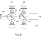
- the illumination system 20a of the embodiment further includes at least one lens 25, which is disposed between the first dichroic element 230 and the second dichroic element 330.
- FIG. 9 is exemplified by having two lenses 25, the quantity of the lens 25 or other optical element is not limited in the invention.
- FIG. 10 is a schematic view of an illumination system in accordance with another embodiment of the invention.
- the illumination system 20b of the embodiment is similar to the illumination system 20 of FIG. 8 , and only the difference between the two is described in the following.
- the illumination system 20b of the embodiment further includes a beam combiner 26, which is disposed among the first light source assembly 200a, the second light source assembly 300a and the third light source assembly 400.
- the first light source assembly 200a and the third light source assembly 400 are disposed on the two opposite sides of the beam combiner 26, respectively.
- the first color beam L1 and the third color beam L3 may be reflected by the beam combiner 26; the second color beam L2 may pass through the beam combiner 26; and so that the first color beam L1, the second color beam L2 and the third color beam L3 may be integrated as the illumination beam L4.
- the beam combiner 26 may be an X beam combiner plate or an X beam combiner prism.
- the first light source assembly 200a and the second light source assembly 300a are similar to the light source assembly 100a in FIG. 3 . That is, in the first light source assembly 200a, the first excitation light source 210 and the second excitation light source 220 are disposed on the same side of the first dichroic element 230a.
- the second excitation beam C2 may be reflected by the first dichroic element 230a; and the first color beam L1 may pass through the first dichroic element 230a and then is transmitted to the beam combiner 26.
- the third excitation light source 310 and the fourth excitation light source 320 are disposed on the same side of the second dichroic element 330a.
- the fourth excitation beam C4 may be reflected by the second dichroic element 330a; and the second color beam L2 may pass through the second dichroic element 330a and then is transmitted to the beam combiner 26.
- FIG. 11 is a schematic view of a projection apparatus in accordance with an embodiment of the invention.
- the projection apparatus 500 of the embodiment includes the illumination system 10 of FIG. 1 , a light valve 170 and a projection lens 180.
- the wavelength conversion beam D provided by the illumination system 10 is transmitted to the light equalizing element 11 (e.g., a light integral rod or a lens array)
- the wavelength conversion beam D first is equalized by the light equalizing element 11 and then is emitted on the light valve 170 uniformly.
- the light valve 170 may be a digital micromirror device (DMD), a liquid crystal on silicon panel (LCoS) or other suitable component.
- the light valve 170 is configured to convert the wavelength conversion beam D into an image beam M.
- the image beam M is then projected into a screen (not shown) through the projection lens 180.
- FIG. 12 is a schematic view of an illumination system in accordance with another embodiment of the invention.
- the illumination system 10F includes a light source assembly 100.
- the light source assembly 100 includes a first excitation light source 110, a second excitation light source 120, a dichroic element 130, a wavelength conversion element 140, a first collimating element 150 and a second collimating element 160.
- the disposition of the first excitation light source 110 and the wavelength conversion element 140 of the embodiment of the invention is as well as the light source assembly of FIG. 2 .
- the first light excitation light source 110 and the wavelength conversion element 140 are packaged together by the transparent resin or other transparent material (not shown).
- This embodiment is the wavelength conversion element 140 disposed between the first excitation light source 110 and the dichroic element 130.
- the wavelength conversion element 140 may be attached the first excitation light source 110, and then adds a transparent protective layer above so as to protect the wavelength conversion element (not shown).
- the first excitation light source 110 is configured to provide a first excitation beam C1.
- the second excitation light source 120 is configured to provide a second excitation beam C2, and the first excitation beam C1 and the second excitation beam C2 have the same color, such as blue, for example.
- the wavelengths of the first excitation beam C1 and the second excitation beam C2 may be located within a certain range. For example, The wavelengths of the first excitation beam C1 and the second excitation beam C2 may be located within in a range 450 ⁇ 475 nm if the two beams are blue.
- the dichroic element 130 is disposed between the first excitation light source 110 and the second excitation light source 120.
- the dichroic element 130 is a dichroic mirror, through which the second excitation beam C2 is transmitted toward the first excitation light source 110.
- the wavelength conversion element 140 is disposed between the first excitation light source 110 and the dichroic element 130.
- the wavelength conversion element 140 is configured to convert the first excitation beam C1 and the second excitation beam C2 into a wavelength conversion beam D and transmit the wavelength conversion beam D toward the dichroic element 130.
- the first collimating element 150 is disposed between the wavelength conversion element 140 and the dichroic element 130.
- the second collimating element 160 is disposed between the second excitation light source 120 and the dichroic element 130.
- the light source assembly has two excitation light sources for providing excitation beams and the two excitation beams excite the wavelength conversion element to emit the wavelength conversion through the two sides of the wavelength conversion element, respectively. Therefore, the optical power of the wavelength conversion beam may be enhanced without increasing the light etendue, and consequentially the illumination system has enhanced optical power of the beam provided by the illumination system.
Description
- The invention relates to an illumination system, and more particularly to an illumination system and a projection apparatus equipped with the illumination system having a wavelength conversion element.
- In
US 2014/347842 A1 a radiation generating apparatus is disclosed. The apparatus comprises a first radiation generating source for generating radiation comprising a first range of wavelengths, a second radiation generating source for generating radiation comprising a second range of wavelengths and a photoluminescent material which is arranged to absorb radiation in the first and second wavelength range and generate radiation comprising a third range of wavelengths. The material comprises a first facet which is arranged to receive radiation from the first radiation source from a first direction and a second facet which is arranged to receive radiation from the second radiation source from a second direction. The first and second directions are substantially collinear, but opposing directions to provide for an increased illumination of the material across the same area of the material. - In
US 2012/099082 A1 an illumination apparatus including a first light emitting device, a first phosphor layer, a second light emitting device and a second phosphor layer and a beam combining element is provided. The first light emitting device is capable of providing a first light beam and the first phosphor layer is disposed on the transmission path of the first light beam. The second light emitting device is disposed opposite to the first light emitting device and for providing a second light beam, wherein the second phosphor layer is disposed on the transmission path of the second light beam. The beam combining element is disposed between the first phosphor layer and the second phosphor layer. In addition, the invention also provides a projection apparatus. -
US 2015/146409 A1 provides a light source apparatus including first and second light sources that output light in mutually opposing directions along a single optical axis; a wavelength conversion element that is disposed between these light sources and that generates light of a wavelength different from that of said light due to irradiation with the light; a first optical member that is disposed between the wavelength conversion element and the first light source, that transmits the light therefrom, and that reflects back light that is scattered towards the first light source, toward the wavelength conversion element; and a second optical member that is disposed between the wavelength conversion element and the second light source, that transmits the light therefrom, and that deflects, in a direction intersecting the optical axis, the light scattered toward the second light source and the light reflected back by the first optical member. -
EP 1 605 199 A2 proposes an illumination device using a wavelength converting element, such as a phosphor layer, that is physically separated from a light source, such as one or more light emitting diodes, a Xenon lamp or a Mercury lamp. The wavelength converting element is optically separated from the light source, so that the converted light emitted by the wavelength converting element is prevented from being incident on the light source. Accordingly, the temperature limitations of the wavelength converting element are removed, thereby permitting the light source to be driven with an increased current to produce a higher radiance. Moreover, by optically separating the wavelength converting element from the light source, the conversion and recycling efficiency of the device is improved, which also increases radiance. - Basically, the projector with the solid-state light source has the following three types of light source systems: lasers, light emitting diodes (LEDs), and a combination of laser and light emitting diodes. Laser light source system usually uses blue laser with fluorescence wheel or phosphor wheel, and the fluorescent wheel contains phosphor layer for exciting red beam or phosphor layer for exciting green beam. LED light source system usually comprises a light emitting diode module for emitting red light, a light emitting diode module for emitting green light and a light emitting diode module for emitting blue light. The light source system with a combination of laser and light emitting diodes usually uses blue laser with fluorescence wheel, wherein the fluorescent wheel contains phosphor for exciting red beam or phosphor for exciting green beam, and the beam with the rest colors are emitted by light emitting diode or laser with specified wavelengths.
- Generally, the existing technology uses dichroic mirror to combine the red, green and blue beams provided by the respective light source modules. However, due to the physical limitation of the dichroic mirror, only one of the red, green or blue light source modules is selected to use. Therefore, when the brightness of image display needs to enhance, either the power of each light source module or the quantity of laser or light emitting diodes in each light source module is required to increase. However, the aforementioned approaches may lead to the following problems: (1) the photoelectric conversion efficiency decreases if simply increasing the power of the light source module, further, the increase in power may disproportionate to the increase in the brightness and the brightness may be saturated; and therefore, the brightness may not be enhanced by indefinitely increasing the power; (2) the component size of the light source system may increase and the entire volume of the light source system may become large if simply increasing the quantity of laser or light emitting diodes; (3) the etendue may increase if simply increasing the quantity of laser or light emitting diodes, and the brightness may not be able to enhance any longer by increasing the quantity of laser or light emitting diodes if the etendue has a mismatch with the designing configuration of the projector or the etendue reaches to the maximum.
- The information disclosed in this "BACKGROUND OF THE INVENTION" section is only for enhancement understanding of the background of the invention and therefore it may contain information that does not form the prior art that is already known to a person of ordinary skill in the art. Furthermore, the information disclosed in this "BACKGROUND OF THE INVENTION" section does not mean that one or more problems to be solved by one or more embodiments of the invention were acknowledged by a person of ordinary skill in the art.
- One object of the invention is to provide an illumination system able to enhance the optical power of the beam provided by the illumination system.
- Another object of the invention is to provide an illumination system including three light source assemblies with various colors, and the illumination system has enhanced optical power of the beam provided by the illumination system.
- Still another object of the invention is to provide an illumination system having enhanced optical power of the wavelength conversion beam without increasing the light etendue; and consequentially, a projection apparatus using the illumination system has enhanced brightness of the images projected onto a screen.
- Other objects and advantages of the invention may be further illustrated by the technical features broadly embodied and described as follows.
- In order to achieve one or a portion of or all of the objects or other objects, the invention provides a projection apparatus according to the independent claim. Advantageous embodiments are described in the dependent claims. It is proposed a projection apparatus comprising a first light source assembly. The first light source assembly comprises a first excitation light source, a second excitation light source, a first dichroic element, a first wavelength conversion element, a first collimating element and a second collimating element. The first excitation light source is configured to provide a first excitation beam. The second excitation light source is configured to provide a second excitation beam. The first excitation beam and the second excitation beam have the same color. The first dichroic element is disposed between the first excitation light source and the second excitation light source. The second excitation beam is transmitted toward the first excitation light source through the first dichroic element. The first wavelength conversion element is disposed between the first excitation light source and the first dichroic element. The first wavelength conversion element is configured to convert the first excitation beam and the second excitation beam into a first wavelength conversion beam and transmit the first wavelength conversion beam toward the first dichroic element. The first collimating element is disposed between the first wavelength conversion element and the first dichroic element. The second collimating element is disposed between the second excitation light source and the first dichroic element.
- Other objectives, features and advantages of the invention will be further understood from the further technological features disclosed by the embodiments of the invention wherein there are shown and described preferred embodiments of this invention, simply by way of illustration of modes best suited to carry out the invention.
- The accompanying drawings are included to provide a further understanding of the invention, and are incorporated in and constitute a part of this specification. The drawings illustrate embodiments of the invention and, together with the description, serve to explain the principles of the invention.
-
FIG. 1 is a schematic view of an illumination system in accordance with an embodiment of the invention; -
FIG. 2 is a schematic cross-sectional view of an element integrated by the wavelength conversion element and the first excitation light source in accordance with an embodiment of the invention; -
FIG. 3 is a schematic view of an illumination system in accordance with another embodiment of the invention; -
FIG. 4 is a schematic view of an illumination system in accordance with another embodiment of the invention; -
FIG. 5 is a schematic view of an illumination system in accordance with another embodiment of the invention; -
FIG. 6 is a schematic view of an illumination system in accordance with another embodiment of the invention; -
FIG. 7 is a schematic view of an illumination system in accordance with another embodiment of the invention; -
FIG. 8 is a schematic view of an illumination system in accordance with another embodiment of the invention; -
FIG. 9 is a schematic view of an illumination system in accordance with another embodiment of the invention; -
FIG. 10 is a schematic view of an illumination system in accordance with another embodiment of the invention; and -
FIG. 11 is a schematic view of a projection apparatus in accordance with an embodiment of the invention. -
FIG. 12 is a schematic view of an illumination system in accordance with an embodiment of the invention. - In the following detailed description of the preferred embodiments, reference is made to the accompanying drawings which form a part hereof, and in which is shown by way of illustration specific embodiments in which the invention may be practiced. In this regard, directional terminology, such as "top", "bottom", "front", "back", etc., is used with reference to the orientation of the Figure(s) being described. The components of the invention may be positioned in a number of different orientations. As such, the directional terminology is used for purposes of illustration and is in no way limiting. On the other hand, the drawings are only schematic and the sizes of components may be exaggerated for clarity. It is to be understood that other embodiments may be utilized and structural changes may be made without departing from the scope of the invention. Also, it is to be understood that the phraseology and terminology used herein are for the purpose of description and should not be regarded as limiting. The use of "including", "comprising", or "having" and variations thereof herein is meant to encompass the items listed thereafter as well as additional items. Unless limited otherwise, the terms "connected", "coupled", and "mounted" and variations thereof herein are used broadly and encompass direct and indirect connections, couplings, and mountings. Similarly, the terms "facing," "faces" and variations thereof herein are used broadly and encompass direct and indirect facing, and "adjacent to" and variations thereof herein are used broadly and encompass directly and indirectly "adjacent to". Therefore, the description of "A" component facing "B" component herein may contain the situations that "A" component directly faces "B" component or one or more additional components are between "A" component and "B" component. Also, the description of "A" component "adjacent to" "B" component herein may contain the situations that "A" component is directly "adjacent to" "B" component or one or more additional components are between "A" component and "B" component. Accordingly, the drawings and descriptions will be regarded as illustrative in nature and not as restrictive.
-
FIG. 1 is a schematic view of an illumination system in accordance with an embodiment of the invention. As shown inFIG. 1 , theillumination system 10 of the embodiment includes alight source assembly 100. Thelight source assembly 100 includes a firstexcitation light source 110, a secondexcitation light source 120, adichroic element 130, awavelength conversion element 140, afirst collimating element 150 and asecond collimating element 160. The firstexcitation light source 110 is configured to provide a first excitation beam C1; the secondexcitation light source 120 is configured to provide a second excitation beam C2; and the first excitation beam C1 and the second excitation beam C2 have the same color, such as blue, for example. The wavelengths of the first excitation beam C1 and the second excitation beam C2 may be located within a certain range, for example, located within in a range 450∼475 nm if the two beams are blue. Thedichroic element 130 is disposed between the firstexcitation light source 110 and the secondexcitation light source 120. In one embodiment, thedichroic element 130 is a dichroic mirror, through which the second excitation beam C2 is transmitted toward the firstexcitation light source 110. Thewavelength conversion element 140 is disposed between the firstexcitation light source 110 and thedichroic element 130. Thewavelength conversion element 140 is configured to convert the first excitation beam C1 and the second excitation beam C2 into a wavelength conversion beam D and transmit the wavelength conversion beam D toward thedichroic element 130. Thefirst collimating element 150 is disposed between thewavelength conversion element 140 and thedichroic element 130. Thesecond collimating element 160 is disposed between the secondexcitation light source 120 and thedichroic element 130. - In the embodiment, the
wavelength conversion element 140 and the firstexcitation light source 110 are two separated elements and have a preset distance apart from each other; wherein the preset distance is not greater than the distance between thewavelength conversion element 140 and thedichroic element 130. The firstexcitation light source 110 may be a light emitting diode, a laser light source or other suitable light source. Similarly, the secondexcitation light source 120 may be a light emitting diode, a laser light source or other suitable source. In another embodiment, a firstexcitation light source 110 may be a light emitting diode chip or a laser diode chip. The structures of the firstexcitation light source 110 and the secondexcitation light source 120 may be the same or not. Thewavelength conversion element 140 has a wavelengthconversion material layer 141 and adichroic layer 142. Thedichroic layer 142 is disposed on the wavelengthconversion material layer 141 and adjacent to the firstexcitation light source 110. In other words, thedichroic layer 142 is disposed between the wavelengthconversion material layer 141 and the firstexcitation light source 110. The wavelengthconversion material layer 141 includes wavelength conversion material such as fluorescent powder or phosphor powder, but the invention is not limited thereto. The surfaces of the wavelengthconversion material layer 141 are configured to absorb the first excitation beam C1 and the second excitation beam C2, and the wavelengthconversion material layer 141 emits the wavelength conversion beam D to thedichroic element 130. The first excitation beam C1 may pass through thedichroic layer 142 and then is transmitted to the wavelengthconversion material layer 141. The wavelength conversion beam D emitted from the wavelength conversion material may be transmitted toward various directions; that is, a portion of the wavelength conversion beam D is transmitted toward thedichroic element 130 and a portion of the wavelength conversion beam D is transmitted toward thedichroic layer 142. Therefore, by using thedichroic layer 142 to reflect the wavelength conversion beam D transmitting toward thedichroic layer 142 so as to direct the wavelength conversion beam D to transmit toward thedichroic element 130, the total optical output of the wavelength conversion beam D transmitting to thedichroic element 130 is increased. - In the embodiment, the first
excitation light source 110 and the secondexcitation light source 120 are disposed on the two sides of thedichroic element 130, respectively. The second excitation beam C2 may pass through thedichroic element 130 and the wavelength conversion beam D may be reflected by thedichroic element 130. After passing through thedichroic element 130, the second excitation beam C2 is transmitted to one side of the wavelengthconversion material layer 141 facing thedichroic element 130. After passing through thedichroic layer 142, the first excitation beam C1 is transmitted to one side of the wavelengthconversion material layer 141 facing thedichroic layer 142. In the embodiment, by using the first excitation beam C1 and the second excitation beam C2 to excite the wavelength conversion material through the two sides of thewavelength conversion element 140, the output of the wavelength conversion beam D is enhanced without increasing the light etendue. - The
first collimating element 150 and thesecond collimating element 160 may have the same configuration. In the embodiment, for example, thefirst collimating element 150 includes acollimating lens 151 and alens 152. Thelens 152 is disposed between thecollimating lens 151 and thedichroic element 130. Thesecond collimating element 160 includes acollimating lens 161 and alens 162. Thelens 162 is disposed between thecollimating lens 161 and thedichroic element 130. In the embodiment, thecollimating lenses lenses first collimating element 150 and thesecond collimating element 160 as well as the quantities of the collimating lens and lens therein are not limited in the invention. Namely, a designer may provide collimating lens and lens with different structures and quantities in response to actual requirements. Further, the optical distance of the second excitation beam C2 from the secondexcitation light source 120 to thedichroic element 130 is equal to the optical distance of the wavelength conversion beam D from thewavelength conversion element 140 to thedichroic element 130. By using thefirst collimating element 150 and thesecond collimating element 160 to control the irradiation range of the second excitation beam C2, the facula of the second excitation beam C2 on thewavelength conversion element 140 is similar to that of the second excitation beam C2 on the light-exitingsurface 121 of the secondexcitation light source 120. In one embodiment, the shape and area size of the light-exitingsurface 121 of the secondexcitation light source 120 are same as those of the light-exitingsurface 143 of thewavelength conversion element 140, respectively. Therefore, the second excitation beam C2 may substantially cover the entirewavelength conversion element 140, thereby improving light utilization and avoiding light losses. - The color configuration of the first excitation beam C1, the second excitation beam C2 and the wavelength conversion beam D may be determined according to actual requirements. For example, the color configuration may be selected from one of: (1) both of the first excitation beam C1 and the second excitation beam C2 are blue light, and the wavelength conversion beam D is green light; (2) both of the first excitation beam C1 and the second excitation beam C2 are blue light, and the wavelength conversion beam D is red light; (3) both of the first excitation beam C1 and the second excitation beam C2 are blue light, and the wavelength conversion beam D is yellow light; and (4) both of the first excitation beam C1 and the second excitation beam C2 are ultraviolet light, and the wavelength conversion beam D is white light.
- As shown in
FIG. 1 , theillumination system 10 of the embodiment may further include other optical element(s), which is disposed on the transmission path of the wavelength conversion beam D after passing through thedichroic element 130. The optical element may include a light equalizing element (e.g., light integral rod or lens array), a lens or a mirror, and the quantity of the aforementioned optical element may be one or more than one.FIG. 1 is exemplified by having a lightintegral rod 11, to which the wavelength conversion beam D is transmitted via thedichroic element 130. In one embodiment, the ratio of the area size of the light-enteringend 11a of the lightintegral rod 11 to the area size of the light-exitingsurface 143 of thewavelength conversion element 140 is ranged from 0.9 to 1.1. The shape of the light-enteringend 11a is similar to that of the light-exitingsurface 143; therefore, the wavelength conversion beam D may be received completely. - In the embodiment, the
wavelength conversion element 140 and the firstexcitation light source 110 are two separated elements. In another embodiment, the wavelength conversion element may be attached to the first excitation light source. For example, the first light excitation light source may be the light emitting diode chip or the laser diode chip. The first light excitation light source and the wavelength conversion element are packaged together by the transparent resin or other transparent material (not shown). This embodiment is the wavelength conversion element disposed between the first excitation light source and the dichroic element. In other embodiment, the wavelength conversion element may be attached the first excitation light source, and then adds a transparent protective layer above so as to protect the wavelength conversion element (not shown). -
FIG. 2 is a schematic cross-sectional view of an element integrated by the wavelength conversion element and the first excitation light source in accordance with an embodiment of the invention. As shown inFIG. 2 , the element includes aconductive carrier 610, areflective layer 620, a hole-transmission layer 630, a light-emittinglayer 640, an electron transmission layer 650 and awavelength conversion layer 660. The layers are sequentially stacked, wherein the positions of the hole-transmission layer 630 and the electron transmission layer 650 are interchangeable. The electrical holes and electrons respectively provided by the hole-transmission layer 630 and the electron transmission layer 650 are combined in the light-emittinglayer 640 to generate photons, and accordingly the light 641 is formed and emitted out from the light-emittinglayer 640. A portion of the light 641 from thelight emitting layer 640 transmitting toward thereflective layer 620 is reflected to thewavelength conversion layer 660, and the portion of light 641 emitting toward thewavelength conversion layer 660 is defined as the first excitation beam C1. Thewavelength conversion layer 660 then converts the first excitation beam C1 into the wavelength conversion beam D and a portion of the wavelength conversion beam D transmitting toward thereflective layer 620 is reflected and then emitted out the element through thewavelength conversion layer 660. -
FIG. 3 is a schematic view of an illumination system in accordance with another embodiment of the invention. As shown inFIG. 3 , theillumination system 10a of the embodiment is similar to theillumination system 10 ofFIG. 1 , and only the difference between the two is described in the following. In theillumination system 10a of the embodiment, the firstexcitation light source 110 and the secondexcitation light source 120 of thelight source assembly 100a are disposed on the same side of thedichroic element 130a. The second excitation beam C2 may be reflected by thedichroic element 130a and the wavelength conversion beam D may pass through thedichroic element 130a. -
FIG. 4 is a schematic view of an illumination system in accordance with another embodiment of the invention. As shown inFIG. 4 , theillumination system 10b of the embodiment is similar to theillumination system 10 ofFIG. 1 , and only the difference between the two is described in the following. Compared with theillumination system 10 ofFIG. 1 , theillumination system 10b of the embodiment further includes acolor wheel 12. Thecolor wheel 12 is disposed on the transmission path of the wavelength conversion beam D reflected by thedichroic element 130. In the embodiment, the first excitation beam C1 and the second excitation beam C2 respectively provided by the firstexcitation light source 110 and the secondexcitation light source 120 are ultraviolet light, and the wavelength conversion beam D emitted from thewavelength conversion element 140 is white light. Per revolution of thecolor wheel 12, the wavelength conversion beam D may be sequentially filtered into beams with various colors, such as red beam R, green beam G and blue beam B, which are transmitted to the lightintegral rod 11 in timing. It is to be noted that the colors of the beams filtered by thecolor wheel 12 and the generating sequence of the beams with various colors are not limited in the invention. -
FIG. 5 is a schematic view of an illumination system in accordance with another embodiment of the invention. As shown inFIG. 5 , theillumination system 10c of the embodiment is similar to theillumination system 10b ofFIG. 4 , and only the difference between the two is described in the following. In theillumination system 10c of the embodiment, the firstexcitation light source 110 and the secondexcitation light source 120 of thelight source assembly 100a are disposed on the same side of thedichroic element 130a. The second excitation beam C2 may be reflected by thedichroic element 130a; and the wavelength conversion beam D may pass through thedichroic element 130a and then is transmitted to thecolor wheel 12. -
FIG. 6 is a schematic view of an illumination system in accordance with another embodiment of the invention. As shown inFIG. 6 , theillumination system 10d of the embodiment is similar to theillumination system 10b ofFIG. 4 , and only the difference between the two is described in the following. In theillumination system 10d of the embodiment, the first excitation beam C1 and the second excitation beam C2 respectively provided by the firstexcitation light source 110 and the secondexcitation light source 120 are blue light, and the wavelength conversion beam D emitted from thewavelength conversion element 140 is yellow light. In addition, theillumination system 10d further includes a bluelight source assembly 13. The bluelight source assembly 13 and the secondexcitation light source 120 are disposed on the same side of thedichroic element 130. The bluelight source assembly 13 is configured to provide a blue beam B1. The blue beam B1 passes through thedichroic element 130 and is combined with wavelength conversion beam D to form a white beam W. The white beam W is then transmitted to thecolor wheel 12. The bluelight source assembly 13 includes a bluelight source 13a and acollimating element 13b. The bluelight source 13a may be a blue light emitting diode, a laser light source, or other suitable light source. Thecollimating element 13b may have a structure same as those of thefirst collimating element 150 and thesecond collimating element 160, for example. -
FIG. 7 is a schematic view of an illumination system in accordance with another embodiment of the invention. As shown inFIG. 7 , theillumination system 10e of the embodiment is similar to theillumination system 10d ofFIG. 6 , and only the difference between the two is described in the following. In theillumination system 10e of the embodiment, the firstexcitation light source 110 and the secondexcitation light source 120 of thelight source assembly 100a are disposed on the same side of thedichroic element 130a. The second excitation beam C2 may be reflected by thedichroic element 130a; and the wavelength conversion beam D may pass through thedichroic element 130a and then is transmitted to thecolor wheel 12. The bluelight source assembly 13 and the secondexcitation light source 120 are disposed on the two sides of thedichroic element 130a. The bluelight source assembly 13 is configured to provide the blue beam B1 to thedichroic element 130a. The blue beam B1 may be reflected by thedichroic element 130 and then combined with the wavelength conversion beam D to form a white beam W. The white beam W is then transmitted to thecolor wheel 12. - Each one of the
illumination systems 10∼10e of the above embodiments has onelight source assembly light source assembly -
FIG. 8 is a schematic view of an illumination system in accordance with another embodiment of the invention. As shown inFIG. 8 , theillumination system 20 of the embodiment includes a firstlight source assembly 200 configured to provided a first color beam L1, a secondlight source assembly 300 configured to provided a second color beam L2, and a thirdlight source assembly 400 configured to provided a third color beam L3; wherein the first color beam L1, the second color beam L2 and the third color beam L3 may be integrated as an illumination beam L4. The firstlight source assembly 200 includes a firstexcitation light source 210, a secondexcitation light source 220, a firstdichroic element 230 and a firstwavelength conversion element 240. The firstexcitation light source 210 is configured to provide a first excitation beam C1; the secondexcitation light source 220 is configured to provide a second excitation beam C2; and the first excitation beam C1 and the second excitation beam C2 have the same color. The firstdichroic element 230 is disposed between the firstexcitation light source 210 and the secondexcitation light source 220. The second excitation beam C2 is transmitted toward the firstexcitation light source 210 via the firstdichroic element 230. The firstwavelength conversion element 240 is disposed between the firstexcitation light source 210 and the firstdichroic element 230. The firstwavelength conversion element 240 is configured to convert the first excitation beam C1 and the second excitation beam C2 into a first wavelength conversion beam and transmit the first wavelength conversion beam toward the firstdichroic element 230; wherein the first wavelength conversion beam is defined as the aforementioned first color beam L1. - The second
light source assembly 300 includes a thirdexcitation light source 310, a fourthexcitation light source 320, a seconddichroic element 330 and a secondwavelength conversion element 340. The thirdexcitation light source 310 is configured to provide a third excitation beam C3; the fourthexcitation light source 320 is configured to provide a fourth excitation beam C4; and the third excitation beam C3 and the fourth excitation beam C4 have the same color. The seconddichroic element 330 is disposed between the thirdexcitation light source 310 and the fourthexcitation light source 320. The fourth excitation beam C4 is transmitted toward the thirdexcitation light source 310 via the seconddichroic element 330. The secondwavelength conversion element 340 is disposed between the thirdexcitation light source 310 and the seconddichroic element 330. The secondwavelength conversion element 340 is configured to convert the third excitation beam C3 and the fourth excitation beam C4 into a second wavelength conversion beam and transmit the second wavelength conversion beam toward the seconddichroic element 330; wherein the second wavelength conversion beam is defined as the aforementioned second color beam L2. - The third
light source assembly 400 includes alight source 410 configured to provide the third color beam L3. Thelight source 410 may be a light emitting diode, a laser light source, or other suitable light source. The thirdlight source assembly 400 may further include acollimating element 420, which is disposed on the transmission path of the third color beam L3. - In the embodiment, the first
light source assembly 200 and the secondlight source assembly 300 have a configuration similar to that of thelight source assembly 100. The firstwavelength conversion element 240 and the secondwavelength conversion element 340 have a structure same as that of thewavelength conversion element 140. In one embodiment, the firstwavelength conversion element 240 and the secondwavelength conversion element 340 may cover the firstexcitation light source 210 and the thirdexcitation light source 310, respectively. In another embodiment, the first wavelength conversion element and the first excitation light source may be integrated as an element similar to that shown inFIG. 2 ; and the second wavelength conversion element and the third excitation light source may be integrated as an element similar to that shown inFIG. 2 . Further, the firstexcitation light source 210, the secondexcitation light source 220, the thirdexcitation light source 310 and the fourthexcitation light source 320 each may be a light emitting diode, a laser light source, or other suitable light source. In addition, the firstlight source assembly 200 may further include afirst collimating element 250, which is disposed between the firstwavelength conversion element 240 and the firstdichroic element 230, and asecond collimating element 260, which is disposed between the secondwavelength conversion element 220 and the firstdichroic element 230. The secondlight source assembly 300 may further include a thirdcollimating element 350, which is disposed between the secondwavelength conversion element 340 and the seconddichroic element 330, and a fourth collimating element 360, which is disposed between the fourthwavelength conversion element 320 and the seconddichroic element 330. - In the embodiment, the second
dichroic element 330 is disposed between the firstdichroic element 230 and the thirdlight source assembly 400; and the third color beam L3 sequentially passes through the seconddichroic element 330 and the firstdichroic element 230. The thirdexcitation light source 310 and the fourthexcitation light source 320 are disposed on the two sides of the seconddichroic element 330, respectively. The fourth excitation beam C4 may pass through the seconddichroic element 330; the second color beam L2 may be reflected to the firstdichroic element 230 by the seconddichroic element 330; and the second color beam L2 may pass through the firstdichroic element 230. The firstexcitation light source 210 and the secondexcitation light source 220 are disposed on the two sides of the firstdichroic element 230, respectively. The second excitation beam C2 may pass through the firstdichroic element 230; the first color beam L1 may be reflected by the firstdichroic element 230, so that the first color beam L1, the second color beam L2 and the third color beam L3 are integrated as the illumination beam L4. - In the embodiment, the first excitation beam C1, the second excitation beam C2, the third excitation beam C3 and the fourth excitation beam C4 are blue light; but the invention is not limited thereto. The first color beam L1 is green light, the second color beam L2 is red light and the third color beam L3 is blue light; but the invention is not limited thereto. In another embodiment, the colors of the first color beam L1 and the second color beam L2 are interchangeable. In addition, the first
light source assembly 200, the secondlight source assembly 300 and the thirdlight source assembly 400 may be configured to simultaneously emit light or not emit light simultaneously. For example, the firstlight source assembly 200, the secondlight source assembly 300 and the thirdlight source assembly 400 may sequentially provide the first color beam L1, the second color beam L2 and the third color beam L3 in timing, respectively; and accordingly, the illumination beam L4 at each time point includes only one of the first color beam L1, the second color beam L2 and the third color beam L3. In another embodiment, the firstlight source assembly 200, the secondlight source assembly 300 and the thirdlight source assembly 400 may simultaneously provide the first color beam L1, the second color beam L2 and the third color beam L3, respectively; and accordingly, the illumination beam L4 at each time point is form by a mix of the first color beam L1, the second color beam L2 and the third color beam L3. - Because the first
light source assembly 200 and the secondlight source assembly 300 have a configuration similar to that of thelight source assembly 100, the optical powers of the first color beam L1 and the second color beam L2 may be enhanced without increasing the light etendue. In addition, theillumination system 20 of the embodiment may further include other optical element(s), which is disposed on the transmission path of the illumination beam L4. The optical element may include a light equalizing element (e.g., light integral rod or lens array), a lens or a mirror, and the quantity of the aforementioned optical element may be one or more than one.FIG. 8 is exemplified by having a lightintegral rod 21. Further, other suitable optical elements may be disposed between the firstdichroic element 230 and the seconddichroic element 330 in response to actual requirements. As shown inFIG. 9 , for example, theillumination system 20a of the embodiment further includes at least onelens 25, which is disposed between the firstdichroic element 230 and the seconddichroic element 330. AlthoughFIG. 9 is exemplified by having twolenses 25, the quantity of thelens 25 or other optical element is not limited in the invention. -
FIG. 10 is a schematic view of an illumination system in accordance with another embodiment of the invention. As shown inFIG. 10 , theillumination system 20b of the embodiment is similar to theillumination system 20 ofFIG. 8 , and only the difference between the two is described in the following. Theillumination system 20b of the embodiment further includes abeam combiner 26, which is disposed among the firstlight source assembly 200a, the secondlight source assembly 300a and the thirdlight source assembly 400. The firstlight source assembly 200a and the thirdlight source assembly 400 are disposed on the two opposite sides of thebeam combiner 26, respectively. The first color beam L1 and the third color beam L3 may be reflected by thebeam combiner 26; the second color beam L2 may pass through thebeam combiner 26; and so that the first color beam L1, the second color beam L2 and the third color beam L3 may be integrated as the illumination beam L4. In the embodiment, thebeam combiner 26 may be an X beam combiner plate or an X beam combiner prism. - In the embodiment, the first
light source assembly 200a and the secondlight source assembly 300a are similar to thelight source assembly 100a inFIG. 3 . That is, in the firstlight source assembly 200a, the firstexcitation light source 210 and the secondexcitation light source 220 are disposed on the same side of the firstdichroic element 230a. The second excitation beam C2 may be reflected by the firstdichroic element 230a; and the first color beam L1 may pass through the firstdichroic element 230a and then is transmitted to thebeam combiner 26. The thirdexcitation light source 310 and the fourthexcitation light source 320 are disposed on the same side of the seconddichroic element 330a. The fourth excitation beam C4 may be reflected by the seconddichroic element 330a; and the second color beam L2 may pass through the seconddichroic element 330a and then is transmitted to thebeam combiner 26. -
FIG. 11 is a schematic view of a projection apparatus in accordance with an embodiment of the invention. As shown inFIG. 11 , theprojection apparatus 500 of the embodiment includes theillumination system 10 ofFIG. 1 , alight valve 170 and aprojection lens 180. When the wavelength conversion beam D provided by theillumination system 10 is transmitted to the light equalizing element 11 (e.g., a light integral rod or a lens array), the wavelength conversion beam D first is equalized by the light equalizingelement 11 and then is emitted on thelight valve 170 uniformly. In the embodiment, thelight valve 170 may be a digital micromirror device (DMD), a liquid crystal on silicon panel (LCoS) or other suitable component. Thelight valve 170 is configured to convert the wavelength conversion beam D into an image beam M. The image beam M is then projected into a screen (not shown) through theprojection lens 180. -
FIG. 12 is a schematic view of an illumination system in accordance with another embodiment of the invention. As shown inFIG. 12 , theillumination system 10F includes alight source assembly 100. Thelight source assembly 100 includes a firstexcitation light source 110, a secondexcitation light source 120, adichroic element 130, awavelength conversion element 140, afirst collimating element 150 and asecond collimating element 160. The disposition of the firstexcitation light source 110 and thewavelength conversion element 140 of the embodiment of the invention is as well as the light source assembly ofFIG. 2 . For example, the first lightexcitation light source 110 and thewavelength conversion element 140 are packaged together by the transparent resin or other transparent material (not shown). This embodiment is thewavelength conversion element 140 disposed between the firstexcitation light source 110 and thedichroic element 130. In other embodiment, thewavelength conversion element 140 may be attached the firstexcitation light source 110, and then adds a transparent protective layer above so as to protect the wavelength conversion element (not shown). - The first
excitation light source 110 is configured to provide a first excitation beam C1. The secondexcitation light source 120 is configured to provide a second excitation beam C2, and the first excitation beam C1 and the second excitation beam C2 have the same color, such as blue, for example. The wavelengths of the first excitation beam C1 and the second excitation beam C2 may be located within a certain range. For example, The wavelengths of the first excitation beam C1 and the second excitation beam C2 may be located within in a range 450∼475 nm if the two beams are blue. Thedichroic element 130 is disposed between the firstexcitation light source 110 and the secondexcitation light source 120. In one embodiment, thedichroic element 130 is a dichroic mirror, through which the second excitation beam C2 is transmitted toward the firstexcitation light source 110. Thewavelength conversion element 140 is disposed between the firstexcitation light source 110 and thedichroic element 130. Thewavelength conversion element 140 is configured to convert the first excitation beam C1 and the second excitation beam C2 into a wavelength conversion beam D and transmit the wavelength conversion beam D toward thedichroic element 130. Thefirst collimating element 150 is disposed between thewavelength conversion element 140 and thedichroic element 130. Thesecond collimating element 160 is disposed between the secondexcitation light source 120 and thedichroic element 130. - In summary, in the illumination system of the invention, the light source assembly has two excitation light sources for providing excitation beams and the two excitation beams excite the wavelength conversion element to emit the wavelength conversion through the two sides of the wavelength conversion element, respectively. Therefore, the optical power of the wavelength conversion beam may be enhanced without increasing the light etendue, and consequentially the illumination system has enhanced optical power of the beam provided by the illumination system.
- The foregoing description of the preferred embodiment of the invention has been presented for purposes of illustration and description. It is not intended to be exhaustive or to limit the invention to the precise form or to exemplary embodiments disclosed. Accordingly, the foregoing description should be regarded as illustrative rather than restrictive. Obviously, many modifications and variations will be apparent to practitioners skilled in this art. The embodiments are chosen and described in order to best explain the principles of the invention and its best mode practical application, thereby to enable persons skilled in the art to understand the invention for various embodiments and with various modifications as are suited to the particular use or implementation contemplated. It is intended that the scope of the invention be defined by the appended claims.
- Therefore, the term "the invention", "the present invention" or the like is not necessary limited the claim scope to a specific embodiment, and the reference to particularly preferred exemplary embodiments of the invention does not imply a limitation on the invention, and no such limitation is to be inferred. The invention is limited only by the scope of the appended claims. Moreover, these claims may refer to use "first", "second", etc. following with noun or element. Such terms should be understood as a nomenclature and should not be construed as giving the limitation on the number of the elements modified by such nomenclature unless specific number has been given. The abstract of the disclosure is provided to comply with the rules requiring an abstract, which will allow a searcher to quickly ascertain the subject matter of the technical disclosure of any patent issued from this disclosure. It is submitted with the understanding that it will not be used to interpret or limit the scope or meaning of the claims. Any advantages and benefits described may not apply to all embodiments of the invention. It should be appreciated that variations may be made in the embodiments described by persons skilled in the art without departing from the scope of the invention as defined by the following claims.
Claims (19)
- A projection apparatus (500) comprising a first light source assembly (100, 200), wherein the first light source assembly (100, 200) comprises:a first excitation light source (110, 210), configured to provide a first excitation beam (C1),a second excitation light source (120, 220), configured to provide a second excitation beam (C2), wherein the first excitation beam (C1) and the second excitation beam (C2) have the same color,a first dichroic element (130, 230), wherein the second excitation beam (C2) is transmitted toward the first excitation light source (110, 210) via the first dichroic element (130, 230),a first wavelength conversion element (140, 240), disposed between the first excitation light source (110, 210) and the first dichroic element (130, 230), wherein the first wavelength conversion element (140, 240) is configured to convert the first excitation beam (C1) and the second excitation beam (C2) into a first wavelength conversion beam and transmit the first wavelength conversion beam toward the first dichroic element (130, 230),a first collimating element (150, 250), disposed between the first wavelength conversion element (140, 240) and the first dichroic element (130, 230), anda second collimating element (160, 260), disposed between the second excitation light source (120, 220) and the first dichroic element (130, 230),characterized in that:the optical distance of the second excitation beam (C2) from the second excitation light source (120, 220) to the first dichroic element (130, 230) is equal to the optical distance of the first wavelength conversion beam from the first wavelength conversion element (140, 240) to the first dichroic element (130, 230),the first collimating element (150, 250) and the second collimating element (160, 260) have the same configuration, andan area size of a light-exiting surface of the second excitation light source (120, 220) is the same as an area size of a light-exiting surface of the wavelength conversion element (140, 240), respectively.
- The projection apparatus (500) according to claim 1, further comprising a light integral rod (11), wherein the first wavelength conversion beam is transmitted to the light integral rod (11) through the first dichroic element (130, 230), and a ratio of an area size of a light-entering end (11a) of the light integral rod (11) to the area size of the light-exiting surface (143) of the wavelength conversion element (140, 240) is ranged from 0.9 to 1.1.
- The projection apparatus (500) according to claim 1, further comprising a lens array, wherein the first wavelength conversion beam is transmitted to the lens array through the first dichroic element (130, 230).
- The projection apparatus (500) according to claim 1, wherein the first excitation light source (110, 210) and the second excitation light source (120, 220) are disposed on the two sides of the first dichroic element (130, 230), respectively, the second excitation beam (C2) passes through the first dichroic element (130, 230), and the first wavelength conversion beam is reflected by the first dichroic element (130, 230), and the first dichroic element (130, 230) is disposed between the first excitation light source (110, 210) and the second excitation light source (120, 220).
- The projection apparatus (500) according to claim 4, further comprising a color wheel (12), disposed on the transmission path of the first wavelength conversion beam reflected by the first dichroic element (130, 230).
- The projection apparatus (500) according to claim 5, wherein both of the first excitation beam (C1) and the second excitation beam (C2) are ultraviolet light and the first wavelength conversion beam is white light.
- The projection apparatus (500) according to claim 1, wherein the first excitation light source (110) and the second excitation light source (120) are disposed on the same side of the first dichroic element (130a), the second excitation beam (C2) is reflected by the first dichroic element (130a), and the first wavelength conversion beam (C1) passes through the first dichroic element (130a).
- The projection apparatus (500) according to claim 7, further comprising a color wheel disposed (12) on the transmission path of the first wavelength conversion beam passing through the first dichroic element (130a).
- The projection apparatus (500) according to claim 8, wherein both of the first excitation beam (C1) and the second excitation beam (C2) are blue light and the first wavelength conversion beam is yellow light, the illumination system further comprises a blue light source assembly (13), the blue light source assembly (13) and the second excitation light source (120) are disposed on the two sides of the first dichroic element (130a), the blue light source assembly (13) is configured to provide a blue beam to the first dichroic element (130a), the blue beam is reflected by the first dichroic element (130a) and is combined with the first wavelength conversion beam (D) to form a white beam, and the white beam is then transmitted to the color wheel (12).
- The projection apparatus (500) according to claim 1, wherein the first wavelength conversion element (140, 240) is attached on the first excitation light source (110, 210).
- The projection apparatus (500) according to claim 1, wherein the first wavelength conversion element (140, 240) and the first excitation light source (110, 210) have a distance, and the distance is not greater than the distance between the first wavelength conversion element (140, 240) and the first dichroic element (130, 230).
- The projection apparatus (500) according to claim 1, further comprising a second light source assembly (300) and a third light source assembly (400), wherein the first light source assembly (200) is configured to provide a first color beam (L1), the second light source assembly (300) is configured to provide a second color beam (L2) and the third light source assembly (400) is configured to provide a third color beam (L3), the first color beam (L1), the second color beam (L2) and the third color beam (L3) are integrated as an illumination beam, and the first wavelength conversion beam is the first color beam (L1).
- The projection apparatus (500) according to claim 12, wherein the second light source assembly (300) comprising:a third excitation light source (310), configured to provide a third excitation beam (C3);a fourth excitation light source (320), configured to provide a fourth excitation beam (C4), wherein the third excitation beam (C3) and the fourth excitation beam (C4) have the same color;a second dichroic element (330), disposed between the third excitation light source (310) and the fourth excitation light source (320), wherein the fourth excitation beam is transmitted toward the third excitation light source (310) through the second dichroic element (330); anda second wavelength conversion element (340), disposed between the third excitation light source (310) and the second dichroic element (330), wherein the second wavelength conversion element (340) is configured to convert the third excitation beam (C3) and the fourth excitation beam (C4) into a second wavelength conversion beam and transmit the second wavelength conversion beam toward the second dichroic element (330), wherein the second wavelength conversion beam is the second color beam.
- The projection apparatus (500) according to claim 13, wherein the second dichroic element (330) is disposed between the first dichroic element (230) and the third light source assembly (400), the third color beam (L3) sequentially passes through the second dichroic element (330) and the first dichroic element (230), the third excitation light source (310) and the fourth excitation light source (320) are disposed on the two sides of the second dichroic element (330), respectively, the fourth excitation beam (C4) passes through the second dichroic element (330), the second color beam (L2) is reflected to the first dichroic element (230) by the second dichroic element (330), the second color beam (L2) passes through the first dichroic element (230), the first excitation light source (210) and the second excitation light source (220) are disposed on the two sides of the first dichroic element (230), respectively, the second excitation beam (C2) passes through the first dichroic element (230), the first color beam (L1) is reflected by the first dichroic element (230), and the first color beam (L1), the second color beam (L2) and the third color beam (L3) is integrated as the illumination beam.
- The projection apparatus (500) according to claim 14, further comprising at least one lens (25) disposed between the first dichroic element (230) and the second dichroic element (330).
- The projection apparatus (500) according to claim 12, further comprising a beam combiner (26) disposed among the first light source assembly (200a), the second light source assembly (300a) and the third light source assembly (400), wherein the first light source assembly (200a) and the third light source assembly (400) are disposed on the two opposite sides of the beam combiner (26), respectively, the first color beam (L1) and the third color beam (L3) are reflected by the beam combiner (26), the second color beam passes through the beam combiner (26), the first color beam (L1), the second color beam (L2) and the third color beam (L3) are integrated as the illumination beam.
- The projection apparatus (500) according to claim 16, wherein the first excitation light source (210) and the second excitation light source (220) are disposed on the same side of the first dichroic element (230a), the second excitation beam (C2) is reflected by the first dichroic element (230a), the first color beam (L1) passes through the first dichroic element (230a) and then is transmitted to the beam combiner (26), the third excitation light source (310) and the fourth excitation light source (320) are disposed on the same side of the second dichroic (330a) element, the fourth excitation beam (C4) is reflected by the second dichroic element (330a), and the second color beam (L2) passes through the second dichroic element (330a) and then is transmitted to the beam combiner.
- The projection apparatus (500) according to claim 13, wherein the first light source assembly (200) further comprises the first collimating element (250), disposed between the first wavelength conversion element (240) and the first dichroic element (230), and a second collimating element (260), disposed between the second excitation light source (220) and the first dichroic element (230);
wherein the second light source assembly (300) further comprises a third collimating element (350), disposed between the second wavelength conversion element (340) and the second dichroic element (330), and a fourth collimating element (360), disposed between the fourth excitation light source (320) and the second dichroic element (330). - The projection apparatus (500) according to claim 1, further comprising a light valve (170) and a projection lens (180), wherein a light equalizing element (11) is disposed on the transmission path of the first wavelength conversion beam and configured to receive the first wavelength conversion beam transmitted from the first dichroic element (130,), wherein the light valve (170) is disposed on the transmission path of the first wavelength conversion beam and configured to convert the first wavelength conversion beam, transmitted from the light equalizing element (11), into an image beam, wherein the projection lens (180) is disposed on the transmission path of the image beam and is configured to project the image beam.
Priority Applications (1)
| Application Number | Priority Date | Filing Date | Title |
|---|---|---|---|
| EP16192627.4A EP3306392B1 (en) | 2016-10-06 | 2016-10-06 | Illumination system and projection apparatus |
Applications Claiming Priority (1)
| Application Number | Priority Date | Filing Date | Title |
|---|---|---|---|
| EP16192627.4A EP3306392B1 (en) | 2016-10-06 | 2016-10-06 | Illumination system and projection apparatus |
Publications (2)
| Publication Number | Publication Date |
|---|---|
| EP3306392A1 EP3306392A1 (en) | 2018-04-11 |
| EP3306392B1 true EP3306392B1 (en) | 2021-05-05 |
Family
ID=57211263
Family Applications (1)
| Application Number | Title | Priority Date | Filing Date |
|---|---|---|---|
| EP16192627.4A Active EP3306392B1 (en) | 2016-10-06 | 2016-10-06 | Illumination system and projection apparatus |
Country Status (1)
| Country | Link |
|---|---|
| EP (1) | EP3306392B1 (en) |
Families Citing this family (2)
| Publication number | Priority date | Publication date | Assignee | Title |
|---|---|---|---|---|
| CN111413841B (en) * | 2019-01-04 | 2023-08-11 | 深圳光峰科技股份有限公司 | Wavelength conversion device, light source system and display device |
| JP2022085665A (en) * | 2020-11-27 | 2022-06-08 | 株式会社リコー | Light source device, image projection device, and light source optical system |
Family Cites Families (7)
| Publication number | Priority date | Publication date | Assignee | Title |
|---|---|---|---|---|
| US7070300B2 (en) * | 2004-06-04 | 2006-07-04 | Philips Lumileds Lighting Company, Llc | Remote wavelength conversion in an illumination device |
| US7547114B2 (en) * | 2007-07-30 | 2009-06-16 | Ylx Corp. | Multicolor illumination device using moving plate with wavelength conversion materials |
| CN102455512B (en) * | 2010-10-21 | 2014-03-12 | 中强光电股份有限公司 | Illumination device and projection device |
| DE102010062465B4 (en) * | 2010-12-06 | 2021-02-04 | Coretronic Corporation | Lighting device |
| WO2013050733A1 (en) * | 2011-10-07 | 2013-04-11 | Cymtec Ltd | Radiation generating apparatus and a method of generating radiation |
| CN103186021B (en) * | 2011-12-27 | 2016-01-20 | 台达电子工业股份有限公司 | Light-source system and Wavelength converter thereof |
| JP5959342B2 (en) * | 2012-07-09 | 2016-08-02 | オリンパス株式会社 | Light source device |
-
2016
- 2016-10-06 EP EP16192627.4A patent/EP3306392B1/en active Active
Also Published As
| Publication number | Publication date |
|---|---|
| EP3306392A1 (en) | 2018-04-11 |
Similar Documents
| Publication | Publication Date | Title |
|---|---|---|
| US10101644B2 (en) | Illumination system and projection apparatus | |
| US9341933B2 (en) | Wavelength conversion and filtering module and light source system | |
| CN107250909B (en) | Illumination device and image projection apparatus | |
| US10379431B2 (en) | Projection apparatus and illumination system having wavelength conversion modules | |
| EP1881367B1 (en) | Projector device, multilayer light-emitting diode device, and reflective light-emitting diode unit | |
| US9033518B2 (en) | Illumination system comprising a rotation wheel with transmissive and reflective regions and a phosphor used for converting a light beam of a first color from the reflective or transmissive region to a second color and projection apparatus | |
| EP3229072B1 (en) | Illumination system and projection apparatus | |
| US10331022B2 (en) | Light source module and projection apparatus | |
| US7744241B2 (en) | High brightness light source using light emitting devices of different wavelengths and wavelength conversion | |
| US20130321777A1 (en) | Illumination system and projection apparatus | |
| CN105278226A (en) | Light source module and projection device | |
| JP6737265B2 (en) | Light conversion device, light source device, and projector | |
| KR102361693B1 (en) | Lighting system | |
| US9977316B2 (en) | Projection apparatus and illumination system thereof | |
| EP2574967A1 (en) | Image generating device with improved illumination efficiency | |
| WO2020088671A1 (en) | Illumination system | |
| US20190253676A1 (en) | Illumination system and projection apparatus | |
| TWI656361B (en) | Illumination system and projection apparatus | |
| CN210072201U (en) | Wavelength conversion module and projection device | |
| EP3306392B1 (en) | Illumination system and projection apparatus | |
| JP6394076B2 (en) | Light source device and projector | |
| US11402738B2 (en) | Illumination system and projection apparatus | |
| US10831091B2 (en) | Projection device and illumination system | |
| JP2018147703A (en) | Light source device | |
| KR102186825B1 (en) | Optical system and image projection device including the same |
Legal Events
| Date | Code | Title | Description |
|---|---|---|---|
| PUAI | Public reference made under article 153(3) epc to a published international application that has entered the european phase |
Free format text: ORIGINAL CODE: 0009012 |
|
| STAA | Information on the status of an ep patent application or granted ep patent |
Free format text: STATUS: THE APPLICATION HAS BEEN PUBLISHED |
|
| AK | Designated contracting states |
Kind code of ref document: A1 Designated state(s): AL AT BE BG CH CY CZ DE DK EE ES FI FR GB GR HR HU IE IS IT LI LT LU LV MC MK MT NL NO PL PT RO RS SE SI SK SM TR |
|
| AX | Request for extension of the european patent |
Extension state: BA ME |
|
| STAA | Information on the status of an ep patent application or granted ep patent |
Free format text: STATUS: REQUEST FOR EXAMINATION WAS MADE |
|
| 17P | Request for examination filed |
Effective date: 20181004 |
|
| RBV | Designated contracting states (corrected) |
Designated state(s): AL AT BE BG CH CY CZ DE DK EE ES FI FR GB GR HR HU IE IS IT LI LT LU LV MC MK MT NL NO PL PT RO RS SE SI SK SM TR |
|
| STAA | Information on the status of an ep patent application or granted ep patent |
Free format text: STATUS: EXAMINATION IS IN PROGRESS |
|
| 17Q | First examination report despatched |
Effective date: 20190802 |
|
| GRAP | Despatch of communication of intention to grant a patent |
Free format text: ORIGINAL CODE: EPIDOSNIGR1 |
|
| STAA | Information on the status of an ep patent application or granted ep patent |
Free format text: STATUS: GRANT OF PATENT IS INTENDED |
|
| INTG | Intention to grant announced |
Effective date: 20201216 |
|
| GRAS | Grant fee paid |
Free format text: ORIGINAL CODE: EPIDOSNIGR3 |
|
| GRAA | (expected) grant |
Free format text: ORIGINAL CODE: 0009210 |
|
| STAA | Information on the status of an ep patent application or granted ep patent |
Free format text: STATUS: THE PATENT HAS BEEN GRANTED |
|
| AK | Designated contracting states |
Kind code of ref document: B1 Designated state(s): AL AT BE BG CH CY CZ DE DK EE ES FI FR GB GR HR HU IE IS IT LI LT LU LV MC MK MT NL NO PL PT RO RS SE SI SK SM TR |
|
| REG | Reference to a national code |
Ref country code: GB Ref legal event code: FG4D |
|
| REG | Reference to a national code |
Ref country code: CH Ref legal event code: EP |
|
| REG | Reference to a national code |
Ref country code: AT Ref legal event code: REF Ref document number: 1390545 Country of ref document: AT Kind code of ref document: T Effective date: 20210515 |
|
| REG | Reference to a national code |
Ref country code: IE Ref legal event code: FG4D |
|
| REG | Reference to a national code |
Ref country code: DE Ref legal event code: R096 Ref document number: 602016057265 Country of ref document: DE |
|
| REG | Reference to a national code |
Ref country code: LT Ref legal event code: MG9D |
|
| REG | Reference to a national code |
Ref country code: AT Ref legal event code: MK05 Ref document number: 1390545 Country of ref document: AT Kind code of ref document: T Effective date: 20210505 |
|
| PG25 | Lapsed in a contracting state [announced via postgrant information from national office to epo] |
Ref country code: AT Free format text: LAPSE BECAUSE OF FAILURE TO SUBMIT A TRANSLATION OF THE DESCRIPTION OR TO PAY THE FEE WITHIN THE PRESCRIBED TIME-LIMIT Effective date: 20210505 Ref country code: BG Free format text: LAPSE BECAUSE OF FAILURE TO SUBMIT A TRANSLATION OF THE DESCRIPTION OR TO PAY THE FEE WITHIN THE PRESCRIBED TIME-LIMIT Effective date: 20210805 Ref country code: HR Free format text: LAPSE BECAUSE OF FAILURE TO SUBMIT A TRANSLATION OF THE DESCRIPTION OR TO PAY THE FEE WITHIN THE PRESCRIBED TIME-LIMIT Effective date: 20210505 Ref country code: FI Free format text: LAPSE BECAUSE OF FAILURE TO SUBMIT A TRANSLATION OF THE DESCRIPTION OR TO PAY THE FEE WITHIN THE PRESCRIBED TIME-LIMIT Effective date: 20210505 Ref country code: LT Free format text: LAPSE BECAUSE OF FAILURE TO SUBMIT A TRANSLATION OF THE DESCRIPTION OR TO PAY THE FEE WITHIN THE PRESCRIBED TIME-LIMIT Effective date: 20210505 |
|
| PG25 | Lapsed in a contracting state [announced via postgrant information from national office to epo] |
Ref country code: IS Free format text: LAPSE BECAUSE OF FAILURE TO SUBMIT A TRANSLATION OF THE DESCRIPTION OR TO PAY THE FEE WITHIN THE PRESCRIBED TIME-LIMIT Effective date: 20210905 Ref country code: GR Free format text: LAPSE BECAUSE OF FAILURE TO SUBMIT A TRANSLATION OF THE DESCRIPTION OR TO PAY THE FEE WITHIN THE PRESCRIBED TIME-LIMIT Effective date: 20210806 Ref country code: LV Free format text: LAPSE BECAUSE OF FAILURE TO SUBMIT A TRANSLATION OF THE DESCRIPTION OR TO PAY THE FEE WITHIN THE PRESCRIBED TIME-LIMIT Effective date: 20210505 Ref country code: SE Free format text: LAPSE BECAUSE OF FAILURE TO SUBMIT A TRANSLATION OF THE DESCRIPTION OR TO PAY THE FEE WITHIN THE PRESCRIBED TIME-LIMIT Effective date: 20210505 Ref country code: RS Free format text: LAPSE BECAUSE OF FAILURE TO SUBMIT A TRANSLATION OF THE DESCRIPTION OR TO PAY THE FEE WITHIN THE PRESCRIBED TIME-LIMIT Effective date: 20210505 Ref country code: NO Free format text: LAPSE BECAUSE OF FAILURE TO SUBMIT A TRANSLATION OF THE DESCRIPTION OR TO PAY THE FEE WITHIN THE PRESCRIBED TIME-LIMIT Effective date: 20210805 Ref country code: PL Free format text: LAPSE BECAUSE OF FAILURE TO SUBMIT A TRANSLATION OF THE DESCRIPTION OR TO PAY THE FEE WITHIN THE PRESCRIBED TIME-LIMIT Effective date: 20210505 Ref country code: PT Free format text: LAPSE BECAUSE OF FAILURE TO SUBMIT A TRANSLATION OF THE DESCRIPTION OR TO PAY THE FEE WITHIN THE PRESCRIBED TIME-LIMIT Effective date: 20210906 |
|
| REG | Reference to a national code |
Ref country code: NL Ref legal event code: MP Effective date: 20210505 |
|
| PG25 | Lapsed in a contracting state [announced via postgrant information from national office to epo] |
Ref country code: NL Free format text: LAPSE BECAUSE OF FAILURE TO SUBMIT A TRANSLATION OF THE DESCRIPTION OR TO PAY THE FEE WITHIN THE PRESCRIBED TIME-LIMIT Effective date: 20210505 |
|
| PG25 | Lapsed in a contracting state [announced via postgrant information from national office to epo] |
Ref country code: CZ Free format text: LAPSE BECAUSE OF FAILURE TO SUBMIT A TRANSLATION OF THE DESCRIPTION OR TO PAY THE FEE WITHIN THE PRESCRIBED TIME-LIMIT Effective date: 20210505 Ref country code: DK Free format text: LAPSE BECAUSE OF FAILURE TO SUBMIT A TRANSLATION OF THE DESCRIPTION OR TO PAY THE FEE WITHIN THE PRESCRIBED TIME-LIMIT Effective date: 20210505 Ref country code: EE Free format text: LAPSE BECAUSE OF FAILURE TO SUBMIT A TRANSLATION OF THE DESCRIPTION OR TO PAY THE FEE WITHIN THE PRESCRIBED TIME-LIMIT Effective date: 20210505 Ref country code: SM Free format text: LAPSE BECAUSE OF FAILURE TO SUBMIT A TRANSLATION OF THE DESCRIPTION OR TO PAY THE FEE WITHIN THE PRESCRIBED TIME-LIMIT Effective date: 20210505 Ref country code: SK Free format text: LAPSE BECAUSE OF FAILURE TO SUBMIT A TRANSLATION OF THE DESCRIPTION OR TO PAY THE FEE WITHIN THE PRESCRIBED TIME-LIMIT Effective date: 20210505 Ref country code: RO Free format text: LAPSE BECAUSE OF FAILURE TO SUBMIT A TRANSLATION OF THE DESCRIPTION OR TO PAY THE FEE WITHIN THE PRESCRIBED TIME-LIMIT Effective date: 20210505 Ref country code: ES Free format text: LAPSE BECAUSE OF FAILURE TO SUBMIT A TRANSLATION OF THE DESCRIPTION OR TO PAY THE FEE WITHIN THE PRESCRIBED TIME-LIMIT Effective date: 20210505 |
|
| REG | Reference to a national code |
Ref country code: DE Ref legal event code: R097 Ref document number: 602016057265 Country of ref document: DE |
|
| PLBE | No opposition filed within time limit |
Free format text: ORIGINAL CODE: 0009261 |
|
| STAA | Information on the status of an ep patent application or granted ep patent |
Free format text: STATUS: NO OPPOSITION FILED WITHIN TIME LIMIT |
|
| 26N | No opposition filed |
Effective date: 20220208 |
|
| PG25 | Lapsed in a contracting state [announced via postgrant information from national office to epo] |
Ref country code: IS Free format text: LAPSE BECAUSE OF FAILURE TO SUBMIT A TRANSLATION OF THE DESCRIPTION OR TO PAY THE FEE WITHIN THE PRESCRIBED TIME-LIMIT Effective date: 20210905 Ref country code: AL Free format text: LAPSE BECAUSE OF FAILURE TO SUBMIT A TRANSLATION OF THE DESCRIPTION OR TO PAY THE FEE WITHIN THE PRESCRIBED TIME-LIMIT Effective date: 20210505 |
|
| REG | Reference to a national code |
Ref country code: CH Ref legal event code: PL |
|
| REG | Reference to a national code |
Ref country code: BE Ref legal event code: MM Effective date: 20211031 |
|
| PG25 | Lapsed in a contracting state [announced via postgrant information from national office to epo] |
Ref country code: MC Free format text: LAPSE BECAUSE OF FAILURE TO SUBMIT A TRANSLATION OF THE DESCRIPTION OR TO PAY THE FEE WITHIN THE PRESCRIBED TIME-LIMIT Effective date: 20210505 |
|
| PG25 | Lapsed in a contracting state [announced via postgrant information from national office to epo] |
Ref country code: LU Free format text: LAPSE BECAUSE OF NON-PAYMENT OF DUE FEES Effective date: 20211006 Ref country code: IT Free format text: LAPSE BECAUSE OF FAILURE TO SUBMIT A TRANSLATION OF THE DESCRIPTION OR TO PAY THE FEE WITHIN THE PRESCRIBED TIME-LIMIT Effective date: 20210505 Ref country code: BE Free format text: LAPSE BECAUSE OF NON-PAYMENT OF DUE FEES Effective date: 20211031 |
|
| PG25 | Lapsed in a contracting state [announced via postgrant information from national office to epo] |
Ref country code: LI Free format text: LAPSE BECAUSE OF NON-PAYMENT OF DUE FEES Effective date: 20211031 Ref country code: CH Free format text: LAPSE BECAUSE OF NON-PAYMENT OF DUE FEES Effective date: 20211031 |
|
| PG25 | Lapsed in a contracting state [announced via postgrant information from national office to epo] |
Ref country code: IE Free format text: LAPSE BECAUSE OF NON-PAYMENT OF DUE FEES Effective date: 20211006 |
|
| PG25 | Lapsed in a contracting state [announced via postgrant information from national office to epo] |
Ref country code: HU Free format text: LAPSE BECAUSE OF FAILURE TO SUBMIT A TRANSLATION OF THE DESCRIPTION OR TO PAY THE FEE WITHIN THE PRESCRIBED TIME-LIMIT; INVALID AB INITIO Effective date: 20161006 |
|
| PG25 | Lapsed in a contracting state [announced via postgrant information from national office to epo] |
Ref country code: CY Free format text: LAPSE BECAUSE OF FAILURE TO SUBMIT A TRANSLATION OF THE DESCRIPTION OR TO PAY THE FEE WITHIN THE PRESCRIBED TIME-LIMIT Effective date: 20210505 |
|
| PGFP | Annual fee paid to national office [announced via postgrant information from national office to epo] |
Ref country code: GB Payment date: 20231025 Year of fee payment: 8 |
|
| PGFP | Annual fee paid to national office [announced via postgrant information from national office to epo] |
Ref country code: FR Payment date: 20231023 Year of fee payment: 8 Ref country code: DE Payment date: 20231027 Year of fee payment: 8 |