JP5959342B2 - Light source device - Google Patents
Light source device Download PDFInfo
- Publication number
- JP5959342B2 JP5959342B2 JP2012153232A JP2012153232A JP5959342B2 JP 5959342 B2 JP5959342 B2 JP 5959342B2 JP 2012153232 A JP2012153232 A JP 2012153232A JP 2012153232 A JP2012153232 A JP 2012153232A JP 5959342 B2 JP5959342 B2 JP 5959342B2
- Authority
- JP
- Japan
- Prior art keywords
- light
- light source
- wavelength conversion
- conversion element
- optical member
- Prior art date
- Legal status (The legal status is an assumption and is not a legal conclusion. Google has not performed a legal analysis and makes no representation as to the accuracy of the status listed.)
- Expired - Fee Related
Links
Images

Classifications
-
- H—ELECTRICITY
- H01—ELECTRIC ELEMENTS
- H01S—DEVICES USING THE PROCESS OF LIGHT AMPLIFICATION BY STIMULATED EMISSION OF RADIATION [LASER] TO AMPLIFY OR GENERATE LIGHT; DEVICES USING STIMULATED EMISSION OF ELECTROMAGNETIC RADIATION IN WAVE RANGES OTHER THAN OPTICAL
- H01S5/00—Semiconductor lasers
- H01S5/005—Optical components external to the laser cavity, specially adapted therefor, e.g. for homogenisation or merging of the beams or for manipulating laser pulses, e.g. pulse shaping
- H01S5/0087—Optical components external to the laser cavity, specially adapted therefor, e.g. for homogenisation or merging of the beams or for manipulating laser pulses, e.g. pulse shaping for illuminating phosphorescent or fluorescent materials, e.g. using optical arrangements specifically adapted for guiding or shaping laser beams illuminating these materials
-
- F—MECHANICAL ENGINEERING; LIGHTING; HEATING; WEAPONS; BLASTING
- F21—LIGHTING
- F21V—FUNCTIONAL FEATURES OR DETAILS OF LIGHTING DEVICES OR SYSTEMS THEREOF; STRUCTURAL COMBINATIONS OF LIGHTING DEVICES WITH OTHER ARTICLES, NOT OTHERWISE PROVIDED FOR
- F21V13/00—Producing particular characteristics or distribution of the light emitted by means of a combination of elements specified in two or more of main groups F21V1/00 - F21V11/00
- F21V13/02—Combinations of only two kinds of elements
- F21V13/08—Combinations of only two kinds of elements the elements being filters or photoluminescent elements and reflectors
-
- F—MECHANICAL ENGINEERING; LIGHTING; HEATING; WEAPONS; BLASTING
- F21—LIGHTING
- F21V—FUNCTIONAL FEATURES OR DETAILS OF LIGHTING DEVICES OR SYSTEMS THEREOF; STRUCTURAL COMBINATIONS OF LIGHTING DEVICES WITH OTHER ARTICLES, NOT OTHERWISE PROVIDED FOR
- F21V13/00—Producing particular characteristics or distribution of the light emitted by means of a combination of elements specified in two or more of main groups F21V1/00 - F21V11/00
- F21V13/12—Combinations of only three kinds of elements
- F21V13/14—Combinations of only three kinds of elements the elements being filters or photoluminescent elements, reflectors and refractors
-
- F—MECHANICAL ENGINEERING; LIGHTING; HEATING; WEAPONS; BLASTING
- F21—LIGHTING
- F21V—FUNCTIONAL FEATURES OR DETAILS OF LIGHTING DEVICES OR SYSTEMS THEREOF; STRUCTURAL COMBINATIONS OF LIGHTING DEVICES WITH OTHER ARTICLES, NOT OTHERWISE PROVIDED FOR
- F21V9/00—Elements for modifying spectral properties, polarisation or intensity of the light emitted, e.g. filters
- F21V9/30—Elements containing photoluminescent material distinct from or spaced from the light source
-
- G—PHYSICS
- G02—OPTICS
- G02B—OPTICAL ELEMENTS, SYSTEMS OR APPARATUS
- G02B19/00—Condensers, e.g. light collectors or similar non-imaging optics
- G02B19/0004—Condensers, e.g. light collectors or similar non-imaging optics characterised by the optical means employed
- G02B19/0028—Condensers, e.g. light collectors or similar non-imaging optics characterised by the optical means employed refractive and reflective surfaces, e.g. non-imaging catadioptric systems
-
- G—PHYSICS
- G02—OPTICS
- G02B—OPTICAL ELEMENTS, SYSTEMS OR APPARATUS
- G02B19/00—Condensers, e.g. light collectors or similar non-imaging optics
- G02B19/0033—Condensers, e.g. light collectors or similar non-imaging optics characterised by the use
- G02B19/0047—Condensers, e.g. light collectors or similar non-imaging optics characterised by the use for use with a light source
- G02B19/0061—Condensers, e.g. light collectors or similar non-imaging optics characterised by the use for use with a light source the light source comprising a LED
-
- G—PHYSICS
- G02—OPTICS
- G02B—OPTICAL ELEMENTS, SYSTEMS OR APPARATUS
- G02B21/00—Microscopes
- G02B21/06—Means for illuminating specimens
- G02B21/08—Condensers
-
- G—PHYSICS
- G02—OPTICS
- G02B—OPTICAL ELEMENTS, SYSTEMS OR APPARATUS
- G02B27/00—Optical systems or apparatus not provided for by any of the groups G02B1/00 - G02B26/00, G02B30/00
- G02B27/10—Beam splitting or combining systems
- G02B27/14—Beam splitting or combining systems operating by reflection only
- G02B27/141—Beam splitting or combining systems operating by reflection only using dichroic mirrors
-
- H—ELECTRICITY
- H01—ELECTRIC ELEMENTS
- H01S—DEVICES USING THE PROCESS OF LIGHT AMPLIFICATION BY STIMULATED EMISSION OF RADIATION [LASER] TO AMPLIFY OR GENERATE LIGHT; DEVICES USING STIMULATED EMISSION OF ELECTROMAGNETIC RADIATION IN WAVE RANGES OTHER THAN OPTICAL
- H01S5/00—Semiconductor lasers
- H01S5/40—Arrangement of two or more semiconductor lasers, not provided for in groups H01S5/02 - H01S5/30
- H01S5/4025—Array arrangements, e.g. constituted by discrete laser diodes or laser bar
-
- G—PHYSICS
- G02—OPTICS
- G02B—OPTICAL ELEMENTS, SYSTEMS OR APPARATUS
- G02B2207/00—Coding scheme for general features or characteristics of optical elements and systems of subclass G02B, but not including elements and systems which would be classified in G02B6/00 and subgroups
- G02B2207/113—Fluorescence
-
- H—ELECTRICITY
- H01—ELECTRIC ELEMENTS
- H01S—DEVICES USING THE PROCESS OF LIGHT AMPLIFICATION BY STIMULATED EMISSION OF RADIATION [LASER] TO AMPLIFY OR GENERATE LIGHT; DEVICES USING STIMULATED EMISSION OF ELECTROMAGNETIC RADIATION IN WAVE RANGES OTHER THAN OPTICAL
- H01S5/00—Semiconductor lasers
- H01S5/005—Optical components external to the laser cavity, specially adapted therefor, e.g. for homogenisation or merging of the beams or for manipulating laser pulses, e.g. pulse shaping
- H01S5/0078—Optical components external to the laser cavity, specially adapted therefor, e.g. for homogenisation or merging of the beams or for manipulating laser pulses, e.g. pulse shaping for frequency filtering
-
- H—ELECTRICITY
- H01—ELECTRIC ELEMENTS
- H01S—DEVICES USING THE PROCESS OF LIGHT AMPLIFICATION BY STIMULATED EMISSION OF RADIATION [LASER] TO AMPLIFY OR GENERATE LIGHT; DEVICES USING STIMULATED EMISSION OF ELECTROMAGNETIC RADIATION IN WAVE RANGES OTHER THAN OPTICAL
- H01S5/00—Semiconductor lasers
- H01S5/30—Structure or shape of the active region; Materials used for the active region
- H01S5/32—Structure or shape of the active region; Materials used for the active region comprising PN junctions, e.g. hetero- or double- heterostructures
- H01S5/323—Structure or shape of the active region; Materials used for the active region comprising PN junctions, e.g. hetero- or double- heterostructures in AIIIBV compounds, e.g. AlGaAs-laser, InP-based laser
- H01S5/32308—Structure or shape of the active region; Materials used for the active region comprising PN junctions, e.g. hetero- or double- heterostructures in AIIIBV compounds, e.g. AlGaAs-laser, InP-based laser emitting light at a wavelength less than 900 nm
- H01S5/32341—Structure or shape of the active region; Materials used for the active region comprising PN junctions, e.g. hetero- or double- heterostructures in AIIIBV compounds, e.g. AlGaAs-laser, InP-based laser emitting light at a wavelength less than 900 nm blue laser based on GaN or GaP
Description
本発明は、光源装置に関するものである。 The present invention relates to a light source device.
従来、液晶プロジェクタなどの光源として半導体光源が用いられている(例えば、特許文献1参照。)。特許文献1では、単一の半導体光源から出力された励起光を3種類の蛍光体に照射して赤色、緑色および青色の蛍光を生成し、これら3色の蛍光を用いて映像の色を再現している。 Conventionally, a semiconductor light source is used as a light source for a liquid crystal projector or the like (see, for example, Patent Document 1). In Patent Document 1, three types of phosphors are irradiated with excitation light output from a single semiconductor light source to generate red, green, and blue fluorescence, and the colors of the image are reproduced using these three colors of fluorescence. doing.
顕微鏡や液晶プロジェクタなどの用途では、光源からの照明光は比較的狭い領域に照射される。特許文献1の装置をこのような用途に適用して狭い領域を照明した場合、Etendueの法則に基づけば、当該狭い領域における照明光の明るさを向上することができないという問題がある。 In applications such as a microscope and a liquid crystal projector, illumination light from a light source is applied to a relatively narrow area. When the apparatus of Patent Document 1 is applied to such a use and a narrow area is illuminated, there is a problem that the brightness of the illumination light in the narrow area cannot be improved based on Etendue's law.
すなわち、光学系のある位置における光束の断面積と光束の立体角との積によって表わされるEtendueは、光源から照射位置まで保存される。特許文献1においては、照明光の明るさを向上するために光源を複数並べることが考えられる。その場合、光源全体としての発光面積が大きくなり、光源側のEtendueが大きくなる。その結果、光源全体の発光面積が増加することにより光源の光量は増加するが、光源側のEtendueも増加して導光効率が低下する。つまり、光源から発せられた全ての光を照射位置において狭い照明領域に効率良く導光することができず、一部は蹴られて照明領域の明るさの向上に寄与しないこととなる。 That is, the Etendue represented by the product of the cross-sectional area of the light beam at a certain position of the optical system and the solid angle of the light beam is stored from the light source to the irradiation position. In Patent Document 1, it is conceivable to arrange a plurality of light sources in order to improve the brightness of illumination light. In that case, the light emission area as a whole of the light source increases, and the Etendue on the light source side increases. As a result, the light emission area of the entire light source increases, so that the amount of light from the light source increases, but the Etendue on the light source side also increases and the light guide efficiency decreases. That is, all the light emitted from the light source cannot be efficiently guided to the narrow illumination area at the irradiation position, and part of the light is kicked and does not contribute to the improvement of the brightness of the illumination area.
本発明は、上述した事情に鑑みてなされたものであって、顕微鏡や液晶プロジェクタのような狭い領域を照明する装置と好適に組み合わせて用いられ照明光の明るさを増大することができる光源装置を提供することを目的とする。 The present invention has been made in view of the above-described circumstances, and is a light source device that can be used in combination with a device that illuminates a narrow region such as a microscope or a liquid crystal projector and can increase the brightness of illumination light. The purpose is to provide.
上記目的を達成するため、本発明は以下の手段を提供する。
本発明は、1つの光軸に沿って互いに向かい合う方向に光を出力する2つの光源と、該2つの光源の間に配置され、これら光源から出力された光が照射されることにより該光とは異なる波長の光を発生する波長変換素子と、該波長変換素子と一方の前記光源との間に配置され、該一方の光源からの光を透過させるとともに前記波長変換素子において発生した光のうち前記一方の光源側に散乱した光を前記波長変換素子の方向に前記光軸と平行に折り返す第1の光学部材と、前記波長変換素子と他方の前記光源との間に配置され、該他方の光源からの光を透過させるとともに、前記波長変換素子において発生した光のうち前記他方の光源側に散乱した光および前記第1の光学部材によって折り返されてきた光を前記光軸に交差する方向に偏向する第2の光学部材とを備える光源装置を提供する。
In order to achieve the above object, the present invention provides the following means.
The present invention includes two light sources that output light in a direction facing each other along one optical axis, and the light source disposed between the two light sources and irradiated with the light output from these light sources. Is disposed between the wavelength conversion element that generates light of a different wavelength, the wavelength conversion element and one of the light sources, and transmits light from the one light source and out of the light generated in the wavelength conversion element A first optical member that folds the light scattered toward the one light source side in the direction of the wavelength conversion element in parallel with the optical axis, and is disposed between the wavelength conversion element and the other light source; The light from the light source is transmitted, and the light scattered in the other light source among the light generated in the wavelength conversion element and the light turned back by the first optical member in a direction intersecting the optical axis. Deflect To provide a light source device and a second optical member.
本発明によれば、2つの光源から出力された光は、波長変換素子において異なる色の光に変換され、一方の光源側に散乱した一部の光は第1の光学部材によって第2の光学部材の方向へと偏向され、他方の光源側に散乱した他の部分の光と重ね合わされる。そして、波長変換素子において発生した光の全体が、第2の光学部材から照明光として出力される。 According to the present invention, the light output from the two light sources is converted into light of a different color in the wavelength conversion element, and a part of the light scattered on the one light source side is subjected to the second optical by the first optical member. It is deflected in the direction of the member and overlapped with the other part of the light scattered on the other light source side. The entire light generated in the wavelength conversion element is output as illumination light from the second optical member.
この場合に、2つの光源からの光により波長変換素子において発生した光の全体の光量は、単一の光源を用いたときのそれと比べて略2倍となる。この発生した光の集光効率は互いに独立した光学系を構成する個々の光源のEtendueによって制限されるので、発生した光全体が十分に狭い領域に集光されることができる。これにより、顕微鏡や液晶プロジェクタのような狭い領域を照明する装置と組み合わせて用いた場合に狭い照明領域における照明光の明るさを増大することができる。 In this case, the total amount of light generated in the wavelength conversion element by the light from the two light sources is approximately twice that when using a single light source. The light collection efficiency of the generated light is limited by the Etendue of each light source constituting an optical system independent of each other, so that the entire generated light can be condensed in a sufficiently narrow region. Thereby, when used in combination with a device that illuminates a narrow area such as a microscope or a liquid crystal projector, the brightness of illumination light in the narrow illumination area can be increased.
上記発明においては、前記波長変換素子が、前記光源から出力された光によって励起される蛍光体または量子ドットを有していてもよい。
このようにすることで、波長変換素子の構成を簡素にすることができる。
In the said invention, the said wavelength conversion element may have the fluorescent substance or quantum dot excited by the light output from the said light source.
By doing in this way, the structure of a wavelength conversion element can be simplified.
また、上記発明においては、前記波長変換素子と前記第1の光学部材との間に配置され、前記波長変換素子から前記一方の光源側に散乱した光を平行光にする第1のコリメート光学系と、前記波長変換素子と前記第2の光学部材との間に配置され、前記波長変換素子から前記他方の光源側に散乱した光を平行光にする第2のコリメート光学系とを備えていてもよい。
このようにすることで、波長変換素子において発生して各方向に散乱した光を、第1のコリメート光学系および第2のコリメート光学系によって平行光にして出力することができる。
Moreover, in the said invention, it arrange | positions between the said wavelength conversion element and the said 1st optical member, The 1st collimating optical system which makes the light scattered from the said wavelength conversion element to the said one light source side parallel light And a second collimating optical system that is arranged between the wavelength conversion element and the second optical member and converts the light scattered from the wavelength conversion element to the other light source side as parallel light. Also good.
By doing in this way, the light which generate | occur | produced in the wavelength conversion element and was scattered in each direction can be output as parallel light by the 1st collimating optical system and the 2nd collimating optical system.
また、上記発明においては、前記第1のコリメート光学系および第2のコリメート光学系うち少なくとも一方が、コリメートレンズまたはロッドインテグレータを備えていてもよい。
このようにすることで、簡素なレンズ構成によって波長変換素子からの散乱光を平行光とすることができる。
In the above invention, at least one of the first collimating optical system and the second collimating optical system may include a collimating lens or a rod integrator.
By doing in this way, the scattered light from a wavelength conversion element can be made into parallel light with a simple lens structure.
また、上記発明においては、前記波長変換素子、前記第1のコリメート光学系および第2のコリメート光学系が、前記光軸上に直列に複数組備えられ、各組の前記波長変換素子が、互いに異なる色の光を発生してもよい。
このようにすることで、共通の光源を用いて複数の波長変換素子から複数の色の光を同時に発生させることができる。また、複数の色の像が時間差で表示されることにより残像として観察者に認識されるカラーブレイクアップが発生することがない。
Moreover, in the said invention, the said wavelength conversion element, the said 1st collimating optical system, and the 2nd collimating optical system are provided with two or more sets in series on the said optical axis, Each said wavelength conversion element is mutually mutually Different colors of light may be generated.
By doing in this way, the light of a several color can be simultaneously generated from a several wavelength conversion element using a common light source. In addition, since a plurality of color images are displayed with a time difference, a color breakup that is recognized by the observer as an afterimage does not occur.
また、上記発明においては、前記第2の光学部材の該第2の光学部材による光の偏向方向とは反対側に配置され、前記第2の光学部材によって偏向される光と同一の光軸に沿って光を出力するもう1つの光源を備え、前記第2の光学部材が、前記もう1つの光源から出力された光も透過させてもよい。
このようにすることで、波長変換素子により発生される光に、もう1つの光源から出力された光を重ね合わせて出力することにより、照明光の明るさをさらに増大することができる。
In the above invention, the second optical member is disposed on the opposite side of the light deflection direction by the second optical member, and has the same optical axis as the light deflected by the second optical member. Another light source that outputs light along the second optical member may be provided, and the second optical member may also transmit light output from the other light source.
In this way, the brightness of the illumination light can be further increased by superimposing and outputting the light output from the other light source on the light generated by the wavelength conversion element.
また、上記発明においては、前記光軸に沿う方向にまたは前記光軸に交差する方向に配列されて前記光源からの光が共に照射されるとともに、互いに異なる色の光を発生する複数の前記波長変換素子を備えていてもよい。
このようにすることで、共通の光源を用いて複数の波長変換素子から複数の色の光を同時に発生させることができる。また、複数の色の像が時間差で表示されることにより残像として観察者に認識されるカラーブレイクアップが発生することがない。
Further, in the above invention, the plurality of wavelengths that are arranged in a direction along the optical axis or in a direction intersecting the optical axis and are irradiated with the light from the light source and generate light of different colors. A conversion element may be provided.
By doing in this way, the light of a several color can be simultaneously generated from a several wavelength conversion element using a common light source. In addition, since a plurality of color images are displayed with a time difference, a color breakup that is recognized by the observer as an afterimage does not occur.
また、上記発明においては、前記2つの光源、波長変換素子、第1の光学部材および第2の光学部材が、該第2の光学部材によって偏向された光の光軸を共通として並列に複数組備えられていてもよい。
このようにすることで、各組において生成された光が第2の光学部材によって偏向されて重ね合わせられた状態で出力される。これにより、複数の色の光を含む照明光を生成することができるとともに、光源の数の増加分だけ照明光の明るさをさらに増大することができる。
In the above invention, the two light sources, the wavelength conversion element, the first optical member, and the second optical member are set in parallel with a common optical axis of the light deflected by the second optical member. It may be provided.
By doing in this way, the light produced | generated in each group is output in the state deflected and superimposed by the 2nd optical member. Thereby, it is possible to generate illumination light including light of a plurality of colors, and it is possible to further increase the brightness of the illumination light by an increase in the number of light sources.
本発明によれば、顕微鏡や液晶プロジェクタのような狭い領域を照明する装置と好適に組み合わせて用いられ照明光の明るさを増大することができるという効果を奏する。 The present invention is advantageously used in combination with a device that illuminates a narrow area such as a microscope or a liquid crystal projector, and has an effect that the brightness of illumination light can be increased.
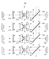
以下に、本発明の一実施形態に係る光源装置1について図面を参照して説明する。
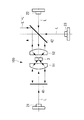
本実施形態に係る光源装置1は、図1に示されるように、1つの光軸Xに沿って互いに向かい合う方向にビーム光を出力する2つの光源21,22と、これら光源21,22の間に配置されビーム光が照射されることにより発光する波長変換素子3と、該波長変換素子3と第1の光源21および第2の光源22との間にそれぞれ配置されたダイクロイックミラー41,42およびコリメート光学系51,52とを備えている。
Below, the light source device 1 which concerns on one Embodiment of this invention is demonstrated with reference to drawings.
As shown in FIG. 1, the light source device 1 according to the present embodiment includes two
第1の光源21および第2の光源22は、指向性の高い単色のビーム光を出力する半導体光源やレーザダイオード(LD)などであり、同一の特性を有するビーム光を出力する。本実施形態においては、単色のビーム光として、450nmの波長を有する青色のレーザ光Lを想定している。各光源21,22は、レーザ光Lを互いに平行に出力する複数(例えば、2個×2個または3個×3個)の半導体光源やLDがアレイ状に配置されて構成されていてもよい。
The
波長変換素子3は、光源21,22からのレーザ光L(単色光)が照射されることにより発光する素子であり、例えば、レーザ光Lによって励起される蛍光体または量子ドットを保持している。本実施形態においては、波長変換素子3として、レーザ光Lの波長450nmを励起波長帯域に含むとともに550nmのピーク波長を有する蛍光L’を発生する蛍光体を想定している。
The
両側からレーザ光Lが照射されることにより波長変換素子3において発生した蛍光L’は、各レーザ光Lの進行方向前方および進行方向後方に散乱する。そして、レーザ光Lによって発生された蛍光L’のうち、第1の光源21側に散乱した一部の蛍光L1’は第1のコリメート光学系51へ入射し、第2の光源22側に散乱した他の部分の蛍光L2’は、第2のコリメート光学系52へ入射する。
The fluorescence L ′ generated in the
第1の光源21と波長変換素子3との間に配置された第1のダイクロイックミラー41は、光軸Xに対して垂直に配置されている。第1のダイクロイックミラー41は、光源21から入射してきたレーザ光Lを光軸Xに沿って透過させ、波長変換素子3から散乱されてきた一部の蛍光L1’を光軸Xに沿って反射する。
The first
第2の光源22と波長変換素子3との間に配置された第2のダイクロイックミラー42は、光軸Xに対して45°傾斜して配置されている。第2のダイクロイックミラー42は、第2の光源22から入射してきたレーザ光Lを光軸Xに沿って透過させ、波長変換素子3から反射されてきた他の部分の蛍光L2’および第1のダイクロイックミラー41によって折り返されて波長変換素子3を通過してきた一部の蛍光L1’を光軸Xと垂直な方向に反射する。
The second
本実施形態においては、第1のダイクロイックミラー41および第2のダイクロイックミラー42として、500nm以下の波長の光を透過させ、500nmよりも長い波長の光を反射する特性を有するものを想定している。
In the present embodiment, it is assumed that the first
第1のコリメート光学系(第1の光学部材)51は、例えば、凸面を第1の光源21側に向けて配置された平凸レンズ(コリメートレンズ)からなる。第1のコリメート光学系51は、波長変換素子3から入射してきた蛍光L1’を平行化してダイクロイックミラー41へ出射するとともに、ダイクロイックミラー41によって反射されて戻ってきた蛍光L1’を波長変換素子3に集光する。
The first collimating optical system (first optical member) 51 includes, for example, a plano-convex lens (collimating lens) arranged with the convex surface facing the
第2のコリメート光学系(第2の光学部材)52は、例えば、凸面を第2の光源22側に向けて配置された平凸レンズ(コリメートレンズ)からなる。第2のコリメート光学系52は、波長変換素子3から入射してきた蛍光L1’,L2’を平行化し、光軸Xに沿って出射する。
なお、第1のコリメート光学系51および第2のコリメート光学系52は、複数のレンズの組み合わせから構成されていてもよい。また、平凸レンズに代えて、ロッドインテグレータを採用してもよい。
The second collimating optical system (second optical member) 52 is composed of, for example, a plano-convex lens (collimating lens) having a convex surface facing the second
The first collimating
次に、このように構成された光源装置1の作用について説明する。
本実施形態に係る光源装置1によれば、2つの光源21,22から出力された青色のレーザ光Lが、1つの光軸Xに沿ってダイクロイックミラー41,42を透過して波長変換素子3に入射することにより、該波長変換素子3において緑色の蛍光L’が発生する。発生した蛍光L’のうち、第2の光源22側に散乱した蛍光L2’は、第2のコリメート光学系52によって平行光とされてから光軸Xに垂直な方向に偏向されて光源装置1の外部へと出力される。
Next, the operation of the light source device 1 configured as described above will be described.
According to the light source device 1 according to the present embodiment, the blue laser light L output from the two
一方、第1の光源21側に散乱した蛍光L1’は、第1のコリメート光学系51によって平行光とされてからダイクロイックミラー41によって折り返され、第1のコリメート光学系51によって波長変換素子3に集光される。ここで、波長変換素子3の発光波長帯域と励起波長帯域との重なりは少ないか或いは全くないので、波長変換素子3に集光された蛍光L1’は、蛍光体を励起させてエネルギー損失を生じさせることは殆どなく、波長変換素子3を透過する。そして、波長変換素子3を透過した蛍光L1’は、第2の光源22側に散乱した蛍光L2’と同様に第2のコリメート光学系52によって平行光とされてから光軸Xに垂直な方向に偏向されて光源装置1の外部へと出力される。これにより、波長変換素子3において発生した蛍光L’全体が最終的な照明光として光源装置1から出力される。
On the other hand, the fluorescence L 1 ′ scattered toward the
光源装置1から出力された照明光は、例えば、顕微鏡やプロジェクタの照明光として用いられる。すなわち、照明光は、顕微鏡の観察試料や液晶プロジェクタが備える液晶パネルなどの照明対象物の狭い領域に集光して照射される。 The illumination light output from the light source device 1 is used as illumination light for a microscope or a projector, for example. That is, the illumination light is condensed and applied to a narrow area of an illumination object such as an observation sample of a microscope or a liquid crystal panel provided in a liquid crystal projector.
この場合に、本実施形態によれば、2つの光源21,22からのレーザ光Lを用いて波長変換素子3から蛍光L’を発生させているので、波長変換素子3における蛍光L’の発生量は単一の光源21/22を用いたときのそれの略2倍となる。ここで、各光源21,22は、他の光学素子3,41,42,51,52を共有しつつ、互いに独立した光学系を構成しているので、各光源21,22の光源側のEtendueは、光源21,22が単独で配置されたと仮定したときのEtendueと同一である。したがって、各光源21,22から出力された各レーザ光Lに起因する蛍光L’は、各光源21,22のEtendueによって制限される十分に狭い領域に集光されることができる。
In this case, according to the present embodiment, since the fluorescence L ′ is generated from the
これにより、照明光の全光束を狭い領域に十分に高い効率で集光することができ、当該狭い領域を照射する照明光の明るさを単一の光源21/22を用いたときのそれと比べて略2倍にまで増大することができるという利点がある。
As a result, the total luminous flux of the illumination light can be collected in a narrow area with sufficiently high efficiency, and the brightness of the illumination light that irradiates the narrow area is compared with that when a single
なお、本実施形態においては、2系統の光源21,22を備えることとしたが、光源の系統数は2以上であればよい。図2は、3系統の光源21,22,23を備えた変形例に係る光源装置100の構成を示している。第3の光源23は、第2のダイクロイックミラー42に対して該第2のダイクロイックミラー42による蛍光L’の偏向方向とは反対側に配置されている。第3の光源23は、LEDとコリメート光学系からなり、第2のダイクロイックミラー42に45°の角度で光Lを入射する。
In the present embodiment, the two
このようにすることで、光源装置100からは、波長変換素子3において発生した緑色の蛍光L’と、第3の光源23からの光Lとが混合された光が照明光として出力される。この場合にも、第1の光源21および第2の光源22とは別系統の第3の光源23からの光Lが蛍光L’に足し合わされるが、第2のダイクロイックミラー42によって波動光学的に重畳されているので、照射対象物側のEtendueは小さくて済む。したがって、光源装置100から出力された照明光L’+Lの全光束を十分に高い効率で狭い領域に集光して明るさを増大することができる。
By doing so, the
また、特開2012−13897号公報に記載の回転型のカラーホイールのように、機械的に素子を駆動することによって複数の色の光を時間差で生成する構成の場合、各色の像が残像として観察者に認識されるカラーブレイクアップが生じる。これに対して、光源装置100によれば、機械的な駆動機構が不要であるので、カラーブレイクアップを生じることなく、複数の色の光L’+Lを同時に発生することができる。
Further, in the case of a configuration in which light of a plurality of colors is generated with a time difference by mechanically driving an element, such as a rotary color wheel described in JP 2012-13897 A, an image of each color is an afterimage. A color break-up that is perceived by the viewer occurs. On the other hand, according to the
また、本実施形態においては、単一の波長変換素子3を用いて単色の蛍光L’を生成することとしたが、これに代えて、複数の波長変換素子3a,3bを用いて複数の色の光を生成することとしてもよい。
Further, in the present embodiment, the single-color fluorescence L ′ is generated using the single
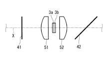
図3に示される変形例においては、光軸Xに沿う方向に配列された2つの波長変換素子3a,3bが備えられている。第1の光源21側に配置された第1の波長変換素子3aは、上述した波長変換素子3と同じく緑色の蛍光L’を発生する。第2の波長変換素子3bは、レーザ光Lの波長450nmを励起波長帯域に含むとともに第1の波長変換素子3aが発生する蛍光L’よりも長い波長、例えば、650nmのピーク波長を有する蛍光を発生する蛍光体を保持している。
In the modification shown in FIG. 3, two
ダイクロイックミラー41,42を透過してきた青色のレーザ光Lが第1の波長変換素子3aおよび第2の波長変換素子3bに入射すると、第1の波長変換素子3aにおいて緑色の蛍光L’が発生し、第2の波長変換素子3bにおいて赤色の蛍光が発生する。これら緑色の蛍光L’と赤色の蛍光のうち、第2の光源22側に散乱した蛍光は第2のコリメート光学系52へ入射する。一方、緑色の蛍光L’と赤色の蛍光のうち第1の光源21側に散乱した蛍光は、ダイクロイックミラー41で折り返されてから、第1のコリメート光学系51、第1の波長変換素子3aおよび第2の波長変換素子3bを通過してから第2のコリメート光学系52へ入射する。
When the blue laser light L transmitted through the
ここで、波長変換素子3a,3bの各発光波長帯域と波長変換素子3a,3bの各励起波長帯域との重なりは少ないか或いは全くないので、蛍光のうち第1の光源21側に散乱した蛍光は、蛍光体を励起させてエネルギー損失を生じさせることは殆どなく、波長変換素子3a,3bを透過する。そして、第1の波長変換素子31および第2の波長変換素子32において発生した蛍光全体が第2のコリメート光学系52から照明光として出力される。
Here, since there is little or no overlap between the emission wavelength bands of the
このようにしても、図2の光源装置100と同様に、カラーブレイクアップを生じることなく、複数の色の光を同時に生成することができる。
Even in this case, similarly to the
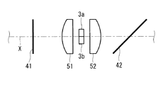
2つの波長変換素子3a,3bは、図4に示されるように、光軸Xに交差する方向に配列されていてもよい。この場合、レーザ光Lが両方の波長変換素子3a,3bに照射されるように、2つの波長変換素子3a,3b同士の隣接面が略光軸X上に配置される。このようにしても、図3の波長変換素子3a,3bと同様に、青色のレーザ光Lから緑色の蛍光L’と赤色の蛍光とを同時に生成することができる。
The two
また、本実施形態においては、図5に示される変形例に係る光源装置200のように、複数組の波長変換素子およびコリメート光学系が直列に備えられていてもよい。この変形例に係る光源装置200では、第1のダイクロイックミラー41と第2のダイクロイックミラー42との間の光軸X上に、複数組(図示する例では2組)の波長変換素子3,3’およびコリメート光学系51,52,51’,52’が、直列に備えられている。
In the present embodiment, a plurality of sets of wavelength conversion elements and collimating optical systems may be provided in series as in the
この場合、後段の組の波長変換素子3’は、図2の波長変換素子3bと同様に、前段の組の波長変換素子3が発生する蛍光L’よりも長い波長(例えば、650nmのピーク波長)を有する蛍光を発生する。すなわち、複数の波長変換素子3,3’は、光軸X上で光源21から離れた位置に配置されるほど、つまり後段側に配置されるほど、発光する光の波長帯域が長波長である蛍光体を保持するように構成されている。前段の組と後段の組との間には、レーザ光Lおよび前段の組の波長変換素子3が発生した蛍光L’を透過させ、後段の組の波長変換素子3’が発生した蛍光を反射するダイクロイックミラー43が備えられている。このようにして、光源装置200は、前段の組の波長変換素子3を通過したレーザ光Lが後段の組の波長変換素子3’を励起して発光させるように構成されている。
In this case, similarly to the
この変形例に係る光源装置200においては、図2に示されるような第3の光源23が備えられていてもよく、また、各組の波長変換素子3,3’として、図3および図4に示されるような複数の波長変換素子3a,3bが採用されてもよい。
このようにしても、カラーブレイクアップを生じることなく、複数の色の光を生成することができる。
In the
Even in this case, light of a plurality of colors can be generated without causing a color breakup.
また、本実施形態においては、光源21,22、波長変換素子3、ダイクロイックミラー41,42およびコリメート光学系51,25が1組備えられていることとしたが、これに代えて、図6に示されるように、ダイクロイックミラー421〜424によって偏向された光の光軸X’を共通として並列に複数組(図示する例では4組)備えられていてもよい。
In the present embodiment, the
この変形例に係る光源装置300において、各組の光源211〜214,221〜224は、上述した光源21,22と同じく青色のレーザ光Lを出力する。波長変換素子31〜34は、互いに異なる色(例えば、水色、緑色、黄色、赤色)の光を発生する。各ダイクロイックミラー411〜414,421〜424の波長特性は適宜設定される。
In the
このようにすることで、4色の光を含む照明光を生成することができる。また、各光源211〜214,221〜224は互いに独立した光学系を構成しているので、照明光の光束全体を個々の光源211〜214,221〜224のEtendueによって制限される十分に狭い領域に集光することができ、当該狭い領域を照射する照明光の明るさを単一の光源を用いたときのそれと比べて略8倍にまで増大することができる。 By doing in this way, the illumination light containing light of four colors can be generated. Moreover, since each light source 211-214, 221-224 comprises the mutually independent optical system, it is a sufficiently narrow area | region where the whole light beam of illumination light is restrict | limited by the Etendue of each light source 211-214, 221-224. The brightness of the illumination light that irradiates the narrow area can be increased to about 8 times compared to that when a single light source is used.
また、本実施形態においては、波長変換素子3が保持する発光体の例として、蛍光体および量子ドットを挙げたが、波長変換素子3の例はこれに限定されるものではない。
また、本実施形態においては、光源装置がコリメート光学系を備えることとしていたが、光源装置の構成はこれに限定されるものではなく、コリメート光学系を備えない構成としてもよい。
Moreover, in this embodiment, although the fluorescent substance and the quantum dot were mentioned as an example of the light-emitting body which the
In the present embodiment, the light source device includes the collimating optical system. However, the configuration of the light source device is not limited to this, and the light source device may not include the collimating optical system.
1,100,200,300 光源装置
21,22,23,211〜214,221〜224 光源
3,3’,3a,3b,31〜34 波長変換素子
41,411〜414 第1のダイクロイックミラー(第1の光学部材)
42,421〜424 第2のダイクロイックミラー(第2の光学部材)
51,511〜514 第1のコリメート光学系
52,521〜524 第2のコリメート光学系
L レーザ光(光)
L’ 蛍光
X 光軸
1, 100, 200, 300
42, 421-424 Second dichroic mirror (second optical member)
51,511-514 First collimating optical system 52,521-524 Second collimating optical system L Laser light (light)
L 'Fluorescence X Optical axis
Claims (8)
該2つの光源の間に配置され、これら光源から出力された光が照射されることにより該光とは異なる波長の光を発生する波長変換素子と、
該波長変換素子と一方の前記光源との間に配置され、該一方の光源からの光を透過させるとともに前記波長変換素子において発生した光のうち前記一方の光源側に散乱した光を前記波長変換素子の方向に前記光軸と平行に折り返す第1の光学部材と、
前記波長変換素子と他方の前記光源との間に配置され、該他方の光源からの光を透過させるとともに、前記波長変換素子において発生した光のうち前記他方の光源側に散乱した光および前記第1の光学部材によって折り返されてきた光を前記光軸に交差する方向に偏向する第2の光学部材とを備える光源装置。 Two light sources that output light in a direction facing each other along one optical axis;
A wavelength conversion element that is disposed between the two light sources and generates light having a wavelength different from the light when irradiated with light output from the light sources;
The wavelength conversion element is disposed between the wavelength conversion element and one of the light sources, transmits light from the one light source, and converts the light scattered in the wavelength conversion element to the one light source side. A first optical member folded back in parallel with the optical axis in the direction of the element;
The light is disposed between the wavelength conversion element and the other light source, transmits light from the other light source, and diffuses light emitted from the wavelength conversion element toward the other light source and the first light source. A light source device comprising: a second optical member that deflects light reflected by the first optical member in a direction intersecting the optical axis.
前記波長変換素子と前記第2の光学部材との間に配置され、前記波長変換素子から前記他方の光源側に散乱した光を平行光にする第2のコリメート光学系とを備える請求項1または請求項2に記載の光源装置。 A first collimating optical system that is disposed between the wavelength conversion element and the first optical member, and collimates light scattered from the wavelength conversion element toward the one light source;
2. A second collimating optical system that is disposed between the wavelength conversion element and the second optical member and converts the light scattered from the wavelength conversion element toward the other light source into parallel light. The light source device according to claim 2.
各組の前記波長変換素子が、互いに異なる色の光を発生する請求項3または請求項4に記載の光源装置。 A plurality of the wavelength conversion element, the first collimating optical system and the second collimating optical system are provided in series on the optical axis;
The light source device according to claim 3, wherein each set of the wavelength conversion elements generates light of different colors.
前記第2の光学部材が、前記もう1つの光源から出力された光も透過させる請求項1から請求項5のいずれかに記載の光源装置。 The second optical member is disposed on the opposite side of the light deflection direction by the second optical member, and outputs light along the same optical axis as the light deflected by the second optical member. With one light source,
The light source device according to claim 1, wherein the second optical member also transmits light output from the other light source.
Priority Applications (3)
| Application Number | Priority Date | Filing Date | Title |
|---|---|---|---|
| JP2012153232A JP5959342B2 (en) | 2012-07-09 | 2012-07-09 | Light source device |
| PCT/JP2013/068216 WO2014010479A1 (en) | 2012-07-09 | 2013-07-03 | Light source unit |
| US14/562,928 US9574745B2 (en) | 2012-07-09 | 2014-12-08 | Light source apparatus |
Applications Claiming Priority (1)
| Application Number | Priority Date | Filing Date | Title |
|---|---|---|---|
| JP2012153232A JP5959342B2 (en) | 2012-07-09 | 2012-07-09 | Light source device |
Publications (3)
| Publication Number | Publication Date |
|---|---|
| JP2014016438A JP2014016438A (en) | 2014-01-30 |
| JP2014016438A5 JP2014016438A5 (en) | 2015-07-23 |
| JP5959342B2 true JP5959342B2 (en) | 2016-08-02 |
Family
ID=49915940
Family Applications (1)
| Application Number | Title | Priority Date | Filing Date |
|---|---|---|---|
| JP2012153232A Expired - Fee Related JP5959342B2 (en) | 2012-07-09 | 2012-07-09 | Light source device |
Country Status (3)
| Country | Link |
|---|---|
| US (1) | US9574745B2 (en) |
| JP (1) | JP5959342B2 (en) |
| WO (1) | WO2014010479A1 (en) |
Families Citing this family (8)
| Publication number | Priority date | Publication date | Assignee | Title |
|---|---|---|---|---|
| JP6141220B2 (en) * | 2014-03-11 | 2017-06-07 | 富士フイルム株式会社 | Endoscope light source device and endoscope system |
| JP6203127B2 (en) * | 2014-06-11 | 2017-09-27 | 富士フイルム株式会社 | Endoscope light source device and endoscope system |
| CN105223761B (en) | 2014-07-01 | 2017-05-24 | 中强光电股份有限公司 | Projection device and illumination system |
| JP6493739B2 (en) * | 2015-02-12 | 2019-04-03 | カシオ計算機株式会社 | Light source device and projection device |
| CN106523955B (en) | 2015-09-14 | 2019-10-11 | 中强光电股份有限公司 | Lighting system and projection arrangement |
| EP4120678A1 (en) | 2016-09-30 | 2023-01-18 | Dolby Laboratories Licensing Corporation | Beam combining for highlight projection |
| EP3306392B1 (en) * | 2016-10-06 | 2021-05-05 | Coretronic Corporation | Illumination system and projection apparatus |
| KR102384695B1 (en) * | 2017-12-07 | 2022-04-08 | 한국전자통신연구원 | Semiconductor laser diode light source package |
Family Cites Families (13)
| Publication number | Priority date | Publication date | Assignee | Title |
|---|---|---|---|---|
| US4710940A (en) * | 1985-10-01 | 1987-12-01 | California Institute Of Technology | Method and apparatus for efficient operation of optically pumped laser |
| US5663979A (en) * | 1995-11-22 | 1997-09-02 | Light Solutions Corporation | Fiber stub end-pumped laser |
| JP2001338502A (en) * | 2000-05-30 | 2001-12-07 | Tokyo Seimitsu Co Ltd | Illuminating optical device |
| JP3594543B2 (en) * | 2000-09-19 | 2004-12-02 | 三洋電機株式会社 | Projection type video display |
| US7070300B2 (en) | 2004-06-04 | 2006-07-04 | Philips Lumileds Lighting Company, Llc | Remote wavelength conversion in an illumination device |
| JP4449976B2 (en) * | 2006-12-26 | 2010-04-14 | セイコーエプソン株式会社 | External resonant laser light source device |
| JP5407664B2 (en) * | 2009-08-27 | 2014-02-05 | セイコーエプソン株式会社 | projector |
| JP2012023013A (en) * | 2010-06-18 | 2012-02-02 | Olympus Medical Systems Corp | Illumination device |
| JP5429079B2 (en) | 2010-06-30 | 2014-02-26 | 株式会社Jvcケンウッド | Light source device and projection display device |
| TWI487998B (en) * | 2010-08-09 | 2015-06-11 | Delta Electronics Inc | Illumination system and projector using the same |
| JP2012093692A (en) * | 2010-09-28 | 2012-05-17 | Ushio Inc | Light radiation device and light radiation method |
| CN102455512B (en) * | 2010-10-21 | 2014-03-12 | 中强光电股份有限公司 | Illumination device and projection device |
| US9075299B2 (en) * | 2011-08-27 | 2015-07-07 | Appotronics Corporation Limited | Light source with wavelength conversion device and filter plate |
-
2012
- 2012-07-09 JP JP2012153232A patent/JP5959342B2/en not_active Expired - Fee Related
-
2013
- 2013-07-03 WO PCT/JP2013/068216 patent/WO2014010479A1/en active Application Filing
-
2014
- 2014-12-08 US US14/562,928 patent/US9574745B2/en active Active
Also Published As
| Publication number | Publication date |
|---|---|
| JP2014016438A (en) | 2014-01-30 |
| US20150146409A1 (en) | 2015-05-28 |
| US9574745B2 (en) | 2017-02-21 |
| WO2014010479A1 (en) | 2014-01-16 |
Similar Documents
| Publication | Publication Date | Title |
|---|---|---|
| JP5959342B2 (en) | Light source device | |
| JP6215989B2 (en) | Illumination system and projection apparatus | |
| JP5527058B2 (en) | Light source device and projector | |
| JP6853862B2 (en) | Light emitting device and projection display device | |
| JP6292523B2 (en) | Wavelength conversion device, illumination optical system, and electronic apparatus using the same | |
| JP5659741B2 (en) | Light source device and projector | |
| KR102088741B1 (en) | Light-emitting device and projection system | |
| JP5673046B2 (en) | Light source device and projector | |
| US9781394B2 (en) | Lighting device having phosphor wheel and excitation radiation source | |
| JP7135909B2 (en) | projector | |
| JP2020101711A (en) | projector | |
| WO2014196079A1 (en) | Light source apparatus and projection display apparatus provided with same | |
| TWM552112U (en) | Light source device and projection system | |
| JP2012189938A (en) | Light source device and projector | |
| JP7071101B2 (en) | Light source device and image projection device | |
| WO2018211886A1 (en) | Projection display device | |
| JP2012079622A (en) | Light source device and projector | |
| JP5541175B2 (en) | Light source device using fluorescent material | |
| CN111176059A (en) | Lighting system | |
| US20150138753A1 (en) | Light-source apparatus | |
| CN110297384B (en) | Light source for projection | |
| JP4944496B2 (en) | LIGHTING DEVICE AND PROJECTOR USING THE LIGHTING DEVICE | |
| EP3617798B1 (en) | Light source apparatus and projector | |
| WO2020031750A1 (en) | Light source device and projector | |
| CN111198475A (en) | Blue light generation method and illumination system |
Legal Events
| Date | Code | Title | Description |
|---|---|---|---|
| A521 | Request for written amendment filed |
Free format text: JAPANESE INTERMEDIATE CODE: A523 Effective date: 20150605 |
|
| A621 | Written request for application examination |
Free format text: JAPANESE INTERMEDIATE CODE: A621 Effective date: 20150605 |
|
| A131 | Notification of reasons for refusal |
Free format text: JAPANESE INTERMEDIATE CODE: A131 Effective date: 20160322 |
|
| A521 | Request for written amendment filed |
Free format text: JAPANESE INTERMEDIATE CODE: A523 Effective date: 20160412 |
|
| TRDD | Decision of grant or rejection written | ||
| A01 | Written decision to grant a patent or to grant a registration (utility model) |
Free format text: JAPANESE INTERMEDIATE CODE: A01 Effective date: 20160531 |
|
| A61 | First payment of annual fees (during grant procedure) |
Free format text: JAPANESE INTERMEDIATE CODE: A61 Effective date: 20160621 |
|
| R151 | Written notification of patent or utility model registration |
Ref document number: 5959342 Country of ref document: JP Free format text: JAPANESE INTERMEDIATE CODE: R151 |
|
| R250 | Receipt of annual fees |
Free format text: JAPANESE INTERMEDIATE CODE: R250 |
|
| R250 | Receipt of annual fees |
Free format text: JAPANESE INTERMEDIATE CODE: R250 |
|
| LAPS | Cancellation because of no payment of annual fees |