WO2014002202A1 - 太陽電池モジュールの製造方法及び太陽電池モジュール - Google Patents
太陽電池モジュールの製造方法及び太陽電池モジュール Download PDFInfo
- Publication number
- WO2014002202A1 WO2014002202A1 PCT/JP2012/066322 JP2012066322W WO2014002202A1 WO 2014002202 A1 WO2014002202 A1 WO 2014002202A1 JP 2012066322 W JP2012066322 W JP 2012066322W WO 2014002202 A1 WO2014002202 A1 WO 2014002202A1
- Authority
- WO
- WIPO (PCT)
- Prior art keywords
- resin sheet
- solar cell
- tan
- filler layer
- colored
- Prior art date
- Legal status (The legal status is an assumption and is not a legal conclusion. Google has not performed a legal analysis and makes no representation as to the accuracy of the status listed.)
- Ceased
Links
Images

Classifications
-
- H—ELECTRICITY
- H10—SEMICONDUCTOR DEVICES; ELECTRIC SOLID-STATE DEVICES NOT OTHERWISE PROVIDED FOR
- H10F—INORGANIC SEMICONDUCTOR DEVICES SENSITIVE TO INFRARED RADIATION, LIGHT, ELECTROMAGNETIC RADIATION OF SHORTER WAVELENGTH OR CORPUSCULAR RADIATION
- H10F71/00—Manufacture or treatment of devices covered by this subclass
- H10F71/137—Batch treatment of the devices
-
- H—ELECTRICITY
- H10—SEMICONDUCTOR DEVICES; ELECTRIC SOLID-STATE DEVICES NOT OTHERWISE PROVIDED FOR
- H10F—INORGANIC SEMICONDUCTOR DEVICES SENSITIVE TO INFRARED RADIATION, LIGHT, ELECTROMAGNETIC RADIATION OF SHORTER WAVELENGTH OR CORPUSCULAR RADIATION
- H10F19/00—Integrated devices, or assemblies of multiple devices, comprising at least one photovoltaic cell covered by group H10F10/00, e.g. photovoltaic modules
- H10F19/80—Encapsulations or containers for integrated devices, or assemblies of multiple devices, having photovoltaic cells
- H10F19/85—Protective back sheets
-
- H—ELECTRICITY
- H10—SEMICONDUCTOR DEVICES; ELECTRIC SOLID-STATE DEVICES NOT OTHERWISE PROVIDED FOR
- H10F—INORGANIC SEMICONDUCTOR DEVICES SENSITIVE TO INFRARED RADIATION, LIGHT, ELECTROMAGNETIC RADIATION OF SHORTER WAVELENGTH OR CORPUSCULAR RADIATION
- H10F77/00—Constructional details of devices covered by this subclass
- H10F77/40—Optical elements or arrangements
- H10F77/413—Optical elements or arrangements directly associated or integrated with the devices, e.g. back reflectors
-
- Y—GENERAL TAGGING OF NEW TECHNOLOGICAL DEVELOPMENTS; GENERAL TAGGING OF CROSS-SECTIONAL TECHNOLOGIES SPANNING OVER SEVERAL SECTIONS OF THE IPC; TECHNICAL SUBJECTS COVERED BY FORMER USPC CROSS-REFERENCE ART COLLECTIONS [XRACs] AND DIGESTS
- Y02—TECHNOLOGIES OR APPLICATIONS FOR MITIGATION OR ADAPTATION AGAINST CLIMATE CHANGE
- Y02E—REDUCTION OF GREENHOUSE GAS [GHG] EMISSIONS, RELATED TO ENERGY GENERATION, TRANSMISSION OR DISTRIBUTION
- Y02E10/00—Energy generation through renewable energy sources
- Y02E10/50—Photovoltaic [PV] energy
Definitions
- the present invention relates to a method for manufacturing a solar cell module and a solar cell module.
- a solar cell module having a solar cell provided in a filler layer disposed between a light receiving surface side protection member and a back surface side protection member is known.
- a portion of the filler layer located between the solar cell and the light-receiving surface side protection member is formed of a transparent ethylene / vinyl acetate copolymer (EVA) film, and the solar cell and the back side protection are formed. It is described that the portion located between the members is made of a colored EVA film.
- Patent Document 1 describes that the output characteristics of a solar cell module can be improved by using a colored EVA film.
- the solar cell module described in Patent Document 1 can be manufactured by, for example, thermocompression bonding a laminate in which a solar cell is disposed between a colored EVA film and a transparent EVA film.
- the colored EVA is also located on the light receiving surface of the solar cell, and the output characteristics of the solar cell module may be deteriorated. is there.
- the main object of the present invention is to improve the output characteristics of the solar cell module.
- a glass plate, a transparent resin sheet, a solar cell, a colored resin sheet, and a first resin sheet are laminated in this order to obtain a laminate.
- the glass plate, the transparent filler layer composed of the transparent resin sheet, the first resin sheet, and the solar cell are arranged between the glass plate and the solar cell.
- a solar cell module having a colored filler layer composed of a colored resin sheet and a first resin sheet is prepared.
- the tan ⁇ at the temperature at the time of pressurization of one of the transparent resin sheet and the colored resin sheet is 1 or more, and the tan ⁇ at the temperature at the time of pressurization of the other resin sheet is less than 1.
- the solar cell according to the present invention includes a glass plate, a resin sheet, a filler layer, and a solar cell.
- the resin sheet is opposed to the glass plate.
- the filler layer is disposed between the glass plate and the resin sheet.
- the solar cell is arranged in the filler layer.
- the filler layer has a transparent filler layer and a colored filler layer.
- the transparent filler layer is located between the solar cell and the glass plate.
- the colored filler layer is located between the solar cell and the resin sheet. Tan ⁇ at 125 ° C. of one of the transparent filler layer and the colored filler layer is 1 or more, and tan ⁇ at 125 ° C. is less than 1.
- the output characteristics of the solar cell module can be improved.
- FIG. 1 is a schematic exploded cross-sectional view of a laminate in one embodiment of the present invention.
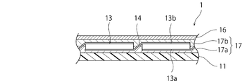
- FIG. 2 is a schematic cross-sectional view of a solar cell module according to an embodiment of the present invention.
- the laminate 10 shown in FIG. 1 is produced. Specifically, the laminated body 10 is produced by laminating
- the transparent resin sheet 12 transmits at least a part of light that can contribute to photoelectric conversion in the solar cell 13. It is preferable that the transparent resin sheet 12 does not substantially contain a pigment and a dye.
- the colored resin sheet 15 reflects at least a part of light that can contribute to photoelectric conversion in the solar cell 13.
- the colored resin sheet 15 preferably contains at least one of a pigment and a dye.
- the colored resin sheet 15 preferably includes, for example, titanium oxide particles.
- the color tone of the colored resin sheet 15 is not necessarily white.
- the color tone of the colored resin sheet 15 may be black, for example.
- one solar cell 13 may be arranged between the transparent resin sheet 12 and the colored resin sheet 15, or a plurality of solar cells 13 electrically connected by the wiring member 14 may be arranged. .
- the type of solar cell 13 is not particularly limited.
- the solar cell 13 may have a substrate made of a crystalline semiconductor material.
- the substrate made of a crystalline semiconductor material include a crystalline silicon substrate.
- the solar cell 13 has a light receiving surface 13a that mainly receives light and a back surface 13b.
- the solar cell 13 is arranged such that the light receiving surface 13a faces the glass plate 11 side and the back surface 13b faces the resin sheet 16 side.
- Resin sheet 16 has flexibility.
- the resin sheet 16 can be composed of, for example, polyethylene terephthalate (PET), vinyl fluoride resin (PVF), polyvinylidene fluoride (PVDF), or a composite thereof.
- the resin sheet 16 may have a barrier layer made of a metal or an inorganic oxide, but is preferably composed of a resin sheet substantially made only of a resin.
- the laminate 10 is pressurized while being heated (heating press process). Thereby, the solar cell module 1 shown by FIG. 2 can be completed.
- the heating temperature of the laminate 10 can be, for example, about 100 ° C. to 160 ° C., preferably about 130 ° C. to 150 ° C.
- the heating temperature of the laminated body 10 can be about 125 degreeC, for example.
- the solar cell module 1 includes a glass plate 11 and a resin sheet 16.
- the resin sheet 16 is opposed to the glass plate 11 with an interval.
- a filler layer 17 composed of the colored resin sheet 15 and the transparent resin sheet 12 is disposed.
- the filler layer 17 includes a transparent filler layer 17 a configured from the transparent resin sheet 12 and a colored filler layer 17 b configured from the colored resin sheet 15.
- the transparent filler layer 17 a is disposed between the glass plate 11 and the solar cell 13.
- the colored filler layer 17 b is disposed between the resin sheet 16 and the solar cell 13. That is, the transparent filler layer 17 a is located on the light receiving surface 13 a side of the solar cell 13, and the colored filler layer 17 b is located on the back surface 13 b side of the solar cell 13.
- the colored resin may also be positioned on the light receiving surface of the solar cell.
- the light that enters the solar cell is reflected or absorbed by the colored resin located on the light receiving surface. For this reason, the incident efficiency of the light to a solar cell falls. As a result, the output characteristics of the solar cell module are degraded.
- the colored resin is positioned relative to the area of the light receiving surface.
- the area ratio tends to increase. Therefore, from the viewpoint of realizing improved output characteristics, it is important to suppress mixing of the molten colored resin sheet and the molten transparent resin sheet.
- tan ⁇ at one of the transparent resin sheet 12 and the colored resin sheet 15 at a temperature (for example, 125 ° C.) during pressurization of the laminate 10 is less than 1, and the other The tan ⁇ at a temperature (for example, 125 ° C.) when the laminate 10 is pressed is 1 or more.
- a resin in which the transparent resin contained in the transparent resin sheet 12 and the colored resin contained in the colored resin sheet 15 are mixed and generated is suppressed from being positioned on the light receiving surface 13a.
- the solar cell module 1 having improved output characteristics can be obtained. Therefore, the output characteristic of the solar cell module 1 is improved by setting tan ⁇ at 125 ° C. of one of the transparent filler layer 17a and the colored filler layer 17b to 1 or more and tan ⁇ at 125 ° C. of less than 1. can do.
- the tan ⁇ at one of the transparent resin sheet 12 and the colored resin sheet 15 at the time of pressurization of the laminate 10 is 0.19 or more. Is preferred.
- Tan ⁇ at one of the transparent resin sheet 12 and the colored resin sheet 15 at the time of pressurization of the laminate 10 is less than 1, and tan ⁇ at the temperature of the other resin sheet at the time of pressurization of the laminate 10.
- the adhesiveness between the transparent filler layer 17a and the colored filler layer 17b is high, and a gap is hardly generated between the transparent filler layer 17a and the colored filler layer 17b. Therefore, the solar cell module 1 having improved moisture resistance can be obtained.
- the stress applied to the solar cell 13 through the transparent resin sheet 12 and the colored resin sheet 15 can be reduced during pressurization. Therefore, it can suppress that a micro crack etc. arise in the solar cell 13.
- tan ⁇ is a loss tangent (loss coefficient) that is a ratio (G ′′ / G ′) of loss elastic modulus (G ′′) to storage elastic modulus (G ′).
- tan ⁇ represents the ratio of the viscous component to the elastic component of the material.
- tan ⁇ is regarded as 1 or more when the measured object is cut off during the measurement of tan ⁇ and cannot be measured.
- a resin sheet having a tan ⁇ at a temperature of pressurization of less than 1 may be used
- a resin sheet having a tan ⁇ at a temperature of pressurization of 1 or more may be used as the transparent resin sheet 15
- the tan ⁇ at 125 ° C. of the colored filler layer 17b may be less than 1
- the tan ⁇ at 125 ° C. of the transparent filler layer 17a may be 1 or more.
- a resin sheet having a tan ⁇ at a temperature of 1 or more may be used, and as the transparent resin sheet 12, a resin sheet having a tan ⁇ at a temperature of 1 may be used.
- the tan ⁇ at 125 ° C. of the colored filler layer 17b may be 1 or more, and the tan ⁇ at 125 ° C. of the transparent filler layer 17a may be less than 1.
- the thermal expansion coefficient of the resin sheet 16 is higher than when the barrier layer is provided. .
- tan ⁇ of the colored resin sheet 15 positioned on the resin sheet 16 is less than 1.
- Tan ⁇ can be measured as follows.
- a rectangular sample in plan view having a length of 5 mm, a width of 10 mm, and a thickness of 0.6 mm is prepared. Then, tan ⁇ of the sample can be obtained by measuring while pulling both ends in the length direction.
- a transparent resin sheet (tan ⁇ is 1 or more at 125 ° C.) and a resin sheet made of non-crosslinkable polyolefin and having a thickness of 0.3 mm were laminated in this order to obtain a laminate.
- the solar cell module was produced by pressurizing the laminated body while heating so that the temperature became 150 ° C.
- Example 2 As the colored resin sheet, a 0.6 mm thick resin sheet made of crosslinkable polyolefin (tan ⁇ is 1 or more at 125 ° C.) is used, and as the transparent resin sheet, a 0.6 mm thick resin sheet made of non-crosslinkable polyolefin (125 ° C. A solar cell module was produced in the same manner as in Example 1 except that tan ⁇ was 0.7).
- Example 1 As the colored resin sheet, a 0.6 mm thick resin sheet made of crosslinkable polyolefin (tan ⁇ is 1 or more at 125 ° C.) is used. As the transparent resin sheet, a 0.6 mm thick resin sheet made of crosslinkable polyolefin (at 125 ° C. A solar cell module was produced in the same manner as in Example 1 except that tan ⁇ was 1 or more.
Landscapes
- Photovoltaic Devices (AREA)
Description
ここでは、図2に示す太陽電池モジュール1の製造方法について、図1及び図2を参照しながら説明する。
(1)着色樹脂シートの一部が受光面13a上に回り込む。
(2)溶融された着色樹脂シートと、溶融された透明樹脂シートとが受光面上において混じり合う。
厚みが3.2mmであるガラス板、非架橋性ポリオレフィンからなる厚み0.6mmである着色樹脂シート(125℃でtanδ=0.7)、太陽電池、架橋性ポリオレフィンからなる厚み0.6mmである透明樹脂シート(125℃にてtanδが1以上)、非架橋性ポリオレフィンからなる厚み0.3mmである樹脂シートとをこの順番で積層し、積層体を得た。次に、積層体を温度が150℃となるように加熱しながら加圧することにより太陽電池モジュールを作製した。
着色樹脂シートとして、架橋性ポリオレフィンからなる厚み0.6mmの樹脂シート(125℃でtanδが1以上)を用い、透明樹脂シートとして、非架橋性ポリオレフィンからなる厚み0.6mmの樹脂シート(125℃でtanδが0.7)を用いたこと以外は実施例1と同様にして太陽電池モジュールを作製した。
着色樹脂シートとして、架橋性ポリオレフィンからなる厚み0.6mmの樹脂シート(125℃でtanδが1以上)を用い、透明樹脂シートとして、架橋性ポリオレフィンからなる厚み0.6mmの樹脂シート(125℃でtanδが1以上)を用いたこと以外は実施例1と同様にして太陽電池モジュールを作製した。
実施例1~2及び比較例1のそれぞれにおいて作製した太陽電池モジュールをガラス板側から確認し、受光面の上に着色された樹脂が存在しているか否かを確認した。その結果、実施例1~2においては、受光面の上には、着色された樹脂が実質的に存在していなかった。比較例1においては、受光面の周縁部の全周に渡って着色された樹脂が存在していた。
10…積層体
11…ガラス板
12…透明樹脂シート
13…太陽電池
13a…受光面
13b…裏面
14…配線材
15…着色樹脂シート
17…充填材層
17a…透明充填材層
17b…着色充填材層
Claims (8)
- ガラス板と、透明樹脂シートと、太陽電池と、着色樹脂シートと、第1の樹脂シートとをこの順番で積層して積層体を得、前記積層体を加熱しながら加圧することにより、前記ガラス板と、前記ガラス板と前記太陽電池との間に配されており、前記透明樹脂シートから構成された透明充填材層と、前記第1の樹脂シートと前記太陽電池との間に配されており、前記着色樹脂シートから構成された着色充填材層と、前記第1の樹脂シートとを有する太陽電池モジュールを作製し、
前記透明樹脂シート及び前記着色樹脂シートのうちの一方の樹脂シートの加圧時の温度におけるtanδが1以上であり、他方の樹脂シートの加圧時の温度におけるtanδが1未満である、太陽電池モジュールの製造方法。 - 請求項1に記載の太陽電池モジュールの製造方法であって、
前記着色樹脂シートとして、加圧時の温度におけるtanδが1未満の樹脂シートを用い、
前記透明樹脂シートとして、加圧時における温度におけるtanδが1以上である樹脂シートを用いる、太陽電池モジュールの製造方法。 - 請求項1に記載の太陽電池モジュールの製造方法であって、
前記着色樹脂シートとして、加圧時の温度におけるtanδが1以上の樹脂シートを用い、
前記透明樹脂シートとして、加圧時における温度におけるtanδが1未満である樹脂シートを用いる、太陽電池モジュールの製造方法。 - 請求項1~3のいずれか一項に記載の太陽電池モジュールの製造方法であって、
前記第1の樹脂シートとして、樹脂からなるシートを用いる、太陽電池モジュールの製造方法。 - ガラス板と、
前記ガラス板と対向する樹脂シートと、
前記ガラス板と前記樹脂シートとの間に配された充填材層と、
前記充填材層中に配された太陽電池と、
を備え、
前記充填材層は、
前記太陽電池と前記ガラス板との間に位置する透明充填材層と、
前記太陽電池と前記樹脂シートとの間に位置する着色充填材層と、
を有し、
前記透明充填材層と前記着色充填材層とのうちの一方の125℃におけるtanδが1以上であり、他方の125℃におけるtanδが1未満である、太陽電池モジュール。 - 請求項5に記載の太陽電池モジュールであって、
前記着色充填材層の125℃におけるtanδが1未満であり、
前記透明充填材層の125℃におけるtanδが1以上である、太陽電池モジュール。 - 請求項5に記載の太陽電池モジュールであって、
前記着色充填材層の125℃におけるtanδが1以上であり、
前記透明充填材層の125℃におけるtanδが1未満である、太陽電池モジュール。 - 請求項5~7のいずれか一項に記載の太陽電池モジュールであって、
前記樹脂シートが、樹脂からなる、太陽電池モジュール。
Priority Applications (4)
| Application Number | Priority Date | Filing Date | Title |
|---|---|---|---|
| PCT/JP2012/066322 WO2014002202A1 (ja) | 2012-06-27 | 2012-06-27 | 太陽電池モジュールの製造方法及び太陽電池モジュール |
| JP2014522282A JP5967593B2 (ja) | 2012-06-27 | 2012-06-27 | 太陽電池モジュールの製造方法及び太陽電池モジュール |
| DE112012006590.5T DE112012006590T5 (de) | 2012-06-27 | 2012-06-27 | Verfahren der Herstellung eines Solarzellenmoduls und Solarzellenmodul |
| US14/578,727 US10411151B2 (en) | 2012-06-27 | 2014-12-22 | Method of manufacturing solar cell module and solar cell module |
Applications Claiming Priority (1)
| Application Number | Priority Date | Filing Date | Title |
|---|---|---|---|
| PCT/JP2012/066322 WO2014002202A1 (ja) | 2012-06-27 | 2012-06-27 | 太陽電池モジュールの製造方法及び太陽電池モジュール |
Related Child Applications (1)
| Application Number | Title | Priority Date | Filing Date |
|---|---|---|---|
| US14/578,727 Continuation US10411151B2 (en) | 2012-06-27 | 2014-12-22 | Method of manufacturing solar cell module and solar cell module |
Publications (1)
| Publication Number | Publication Date |
|---|---|
| WO2014002202A1 true WO2014002202A1 (ja) | 2014-01-03 |
Family
ID=49782434
Family Applications (1)
| Application Number | Title | Priority Date | Filing Date |
|---|---|---|---|
| PCT/JP2012/066322 Ceased WO2014002202A1 (ja) | 2012-06-27 | 2012-06-27 | 太陽電池モジュールの製造方法及び太陽電池モジュール |
Country Status (4)
| Country | Link |
|---|---|
| US (1) | US10411151B2 (ja) |
| JP (1) | JP5967593B2 (ja) |
| DE (1) | DE112012006590T5 (ja) |
| WO (1) | WO2014002202A1 (ja) |
Cited By (3)
| Publication number | Priority date | Publication date | Assignee | Title |
|---|---|---|---|---|
| JP2016032008A (ja) * | 2014-07-28 | 2016-03-07 | 大日本印刷株式会社 | 太陽電池モジュール用の封止材シート及びその製造方法 |
| JP2016157760A (ja) * | 2015-02-24 | 2016-09-01 | 大日本印刷株式会社 | 太陽電池モジュール用の有色封止材シート |
| JP2024119918A (ja) * | 2018-04-16 | 2024-09-03 | セ エス エ エム サントル スイス デレクトロニク エ ド ミクロテクニク ソシエテ アノニム ルシェルシェ エ ディベロップメント | 光電池モジュール及び当該光電池モジュールの製造方法 |
Citations (3)
| Publication number | Priority date | Publication date | Assignee | Title |
|---|---|---|---|---|
| JP2003258283A (ja) * | 2002-02-27 | 2003-09-12 | Bridgestone Corp | 太陽電池及び太陽電池用接着フィルム |
| JP2011216804A (ja) * | 2010-04-02 | 2011-10-27 | Bridgestone Corp | 太陽電池用封止膜、これを用いた太陽電池、及び太陽電池の製造方法 |
| WO2012073751A1 (ja) * | 2010-11-30 | 2012-06-07 | 三洋電機株式会社 | 太陽電池モジュール及びその製造方法 |
Family Cites Families (14)
| Publication number | Priority date | Publication date | Assignee | Title |
|---|---|---|---|---|
| JP2915327B2 (ja) * | 1995-07-19 | 1999-07-05 | キヤノン株式会社 | 太陽電池モジュール及びその製造方法 |
| JP3222361B2 (ja) * | 1995-08-15 | 2001-10-29 | キヤノン株式会社 | 太陽電池モジュールの製造方法及び太陽電池モジュール |
| US6414236B1 (en) * | 1999-06-30 | 2002-07-02 | Canon Kabushiki Kaisha | Solar cell module |
| WO2004038811A1 (ja) * | 2002-10-25 | 2004-05-06 | Nakajima Glass Co., Inc. | 太陽電池モジュールの製造方法 |
| JP2004288677A (ja) * | 2003-03-19 | 2004-10-14 | Sharp Corp | 太陽電池モジュールサブアセンブリおよび複層ガラス型太陽電池モジュール |
| EP2248852B8 (en) * | 2004-11-25 | 2012-05-16 | Mitsui Chemicals, Inc. | Propylene resin composition and use thereof |
| US20100154867A1 (en) * | 2008-12-19 | 2010-06-24 | E. I. Du Pont De Nemours And Company | Mechanically reliable solar cell modules |
| JP5525847B2 (ja) * | 2009-03-17 | 2014-06-18 | 日本ポリプロ株式会社 | プロピレン系多層シートおよびそれを用いた加圧処理用包装袋 |
| US20140130851A1 (en) * | 2009-11-02 | 2014-05-15 | Keiwa Inc. | Tacky sheet for protecting back face of solar battery module, and solar battery module using the same |
| EP2530736B1 (en) * | 2010-01-26 | 2016-07-20 | Sekisui Chemical Co., Ltd. | Sealing material for solar cell, protective sheet for solar cell, process for production of solar cell module |
| JP5793498B2 (ja) * | 2010-08-23 | 2015-10-14 | 株式会社クラレ | 太陽電池用封止材および合わせガラス用中間膜 |
| WO2012043304A1 (ja) * | 2010-09-30 | 2012-04-05 | 積水化学工業株式会社 | フレキシブル太陽電池モジュールの製造方法 |
| US20130210186A1 (en) * | 2010-11-18 | 2013-08-15 | Sekisui Chemical Co., Ltd. | Method for manufacturing flexible solar cell module |
| TWI534235B (zh) * | 2011-02-18 | 2016-05-21 | 3M新設資產公司 | 光學透明黏著劑,其使用方法,及得自其之物件 |
-
2012
- 2012-06-27 JP JP2014522282A patent/JP5967593B2/ja not_active Expired - Fee Related
- 2012-06-27 DE DE112012006590.5T patent/DE112012006590T5/de not_active Ceased
- 2012-06-27 WO PCT/JP2012/066322 patent/WO2014002202A1/ja not_active Ceased
-
2014
- 2014-12-22 US US14/578,727 patent/US10411151B2/en not_active Expired - Fee Related
Patent Citations (3)
| Publication number | Priority date | Publication date | Assignee | Title |
|---|---|---|---|---|
| JP2003258283A (ja) * | 2002-02-27 | 2003-09-12 | Bridgestone Corp | 太陽電池及び太陽電池用接着フィルム |
| JP2011216804A (ja) * | 2010-04-02 | 2011-10-27 | Bridgestone Corp | 太陽電池用封止膜、これを用いた太陽電池、及び太陽電池の製造方法 |
| WO2012073751A1 (ja) * | 2010-11-30 | 2012-06-07 | 三洋電機株式会社 | 太陽電池モジュール及びその製造方法 |
Cited By (4)
| Publication number | Priority date | Publication date | Assignee | Title |
|---|---|---|---|---|
| JP2016032008A (ja) * | 2014-07-28 | 2016-03-07 | 大日本印刷株式会社 | 太陽電池モジュール用の封止材シート及びその製造方法 |
| JP2016157760A (ja) * | 2015-02-24 | 2016-09-01 | 大日本印刷株式会社 | 太陽電池モジュール用の有色封止材シート |
| JP2024119918A (ja) * | 2018-04-16 | 2024-09-03 | セ エス エ エム サントル スイス デレクトロニク エ ド ミクロテクニク ソシエテ アノニム ルシェルシェ エ ディベロップメント | 光電池モジュール及び当該光電池モジュールの製造方法 |
| JP7673297B2 (ja) | 2018-04-16 | 2025-05-08 | セ エス エ エム サントル スイス デレクトロニク エ ド ミクロテクニク ソシエテ アノニム ルシェルシェ エ ディベロップメント | 光電池モジュール及び当該光電池モジュールの製造方法 |
Also Published As
| Publication number | Publication date |
|---|---|
| DE112012006590T5 (de) | 2015-03-19 |
| JP5967593B2 (ja) | 2016-08-10 |
| JPWO2014002202A1 (ja) | 2016-05-26 |
| US20150118783A1 (en) | 2015-04-30 |
| US10411151B2 (en) | 2019-09-10 |
Similar Documents
| Publication | Publication Date | Title |
|---|---|---|
| US20130209776A1 (en) | Back sheet of a solar cell module for photovoltaic power generation | |
| JP5710451B2 (ja) | 太陽電池用バックシート及びその製造方法、並びに、太陽電池モジュール | |
| US20130167928A1 (en) | Solar cell sealing sheet and flexible solar cell module | |
| US20130247963A1 (en) | Solar cell module and manufacturing method therefor | |
| US10236404B2 (en) | Back sheet and solar cell module including the same | |
| US11049987B2 (en) | Solar module and method of manufacturing the same | |
| JP5967593B2 (ja) | 太陽電池モジュールの製造方法及び太陽電池モジュール | |
| JP2011049228A (ja) | 太陽電池モジュール用裏面一体化シート | |
| WO2014033829A1 (ja) | 太陽電池モジュール | |
| JP6241756B2 (ja) | 太陽電池モジュールの製造方法及び太陽電池モジュール | |
| US9484478B2 (en) | Solar cell module | |
| TWI474492B (zh) | 增強光捕捉之太陽光電模組 | |
| JP2012109414A (ja) | 太陽電池モジュール | |
| JP2014179513A (ja) | 太陽電池モジュール及びその製造方法 | |
| JP2015195297A (ja) | 太陽電池モジュール | |
| CN104282785B (zh) | 光伏组件及其制备方法 | |
| JP2005236217A (ja) | 太陽電池モジュール用封止材及びこれを用いた太陽電池モジュールの製造方法 | |
| JP2014239138A (ja) | 太陽電池モジュールの製造方法及び太陽電池モジュール | |
| WO2013187236A1 (ja) | 太陽電池モジュールおよび接着層 | |
| JP2015088728A (ja) | 裏側保護基材、太陽電池モジュール、及び太陽電池モジュールの製造方法 | |
| WO2012165003A1 (ja) | 太陽電池モジュール及びその製造方法 | |
| WO2015045673A1 (ja) | 太陽電池モジュールの製造方法 | |
| JP5923740B2 (ja) | 太陽電池モジュール及びその製造方法 | |
| WO2014045974A1 (ja) | 太陽電池モジュール | |
| JP2012204735A (ja) | 結晶系シリコン太陽電池モジュールの封止膜形成用樹脂シート |
Legal Events
| Date | Code | Title | Description |
|---|---|---|---|
| 121 | Ep: the epo has been informed by wipo that ep was designated in this application |
Ref document number: 12879653 Country of ref document: EP Kind code of ref document: A1 |
|
| ENP | Entry into the national phase |
Ref document number: 2014522282 Country of ref document: JP Kind code of ref document: A |
|
| WWE | Wipo information: entry into national phase |
Ref document number: 1120120065905 Country of ref document: DE Ref document number: 112012006590 Country of ref document: DE |
|
| 122 | Ep: pct application non-entry in european phase |
Ref document number: 12879653 Country of ref document: EP Kind code of ref document: A1 |