WO2013191214A1 - 湾曲センサ - Google Patents
湾曲センサ Download PDFInfo
- Publication number
- WO2013191214A1 WO2013191214A1 PCT/JP2013/066869 JP2013066869W WO2013191214A1 WO 2013191214 A1 WO2013191214 A1 WO 2013191214A1 JP 2013066869 W JP2013066869 W JP 2013066869W WO 2013191214 A1 WO2013191214 A1 WO 2013191214A1
- Authority
- WO
- WIPO (PCT)
- Prior art keywords
- bending
- unit
- light
- sensor
- holding
- Prior art date
Links
Images


Classifications
-
- G—PHYSICS
- G01—MEASURING; TESTING
- G01B—MEASURING LENGTH, THICKNESS OR SIMILAR LINEAR DIMENSIONS; MEASURING ANGLES; MEASURING AREAS; MEASURING IRREGULARITIES OF SURFACES OR CONTOURS
- G01B11/00—Measuring arrangements characterised by the use of optical techniques
- G01B11/24—Measuring arrangements characterised by the use of optical techniques for measuring contours or curvatures
-
- A—HUMAN NECESSITIES
- A61—MEDICAL OR VETERINARY SCIENCE; HYGIENE
- A61B—DIAGNOSIS; SURGERY; IDENTIFICATION
- A61B1/00—Instruments for performing medical examinations of the interior of cavities or tubes of the body by visual or photographical inspection, e.g. endoscopes; Illuminating arrangements therefor
- A61B1/00131—Accessories for endoscopes
- A61B1/00135—Oversleeves mounted on the endoscope prior to insertion
-
- A—HUMAN NECESSITIES
- A61—MEDICAL OR VETERINARY SCIENCE; HYGIENE
- A61B—DIAGNOSIS; SURGERY; IDENTIFICATION
- A61B1/00—Instruments for performing medical examinations of the interior of cavities or tubes of the body by visual or photographical inspection, e.g. endoscopes; Illuminating arrangements therefor
- A61B1/005—Flexible endoscopes
- A61B1/009—Flexible endoscopes with bending or curvature detection of the insertion part
-
- A—HUMAN NECESSITIES
- A61—MEDICAL OR VETERINARY SCIENCE; HYGIENE
- A61B—DIAGNOSIS; SURGERY; IDENTIFICATION
- A61B1/00—Instruments for performing medical examinations of the interior of cavities or tubes of the body by visual or photographical inspection, e.g. endoscopes; Illuminating arrangements therefor
- A61B1/00002—Operational features of endoscopes
- A61B1/00011—Operational features of endoscopes characterised by signal transmission
- A61B1/00013—Operational features of endoscopes characterised by signal transmission using optical means
-
- A—HUMAN NECESSITIES
- A61—MEDICAL OR VETERINARY SCIENCE; HYGIENE
- A61B—DIAGNOSIS; SURGERY; IDENTIFICATION
- A61B1/00—Instruments for performing medical examinations of the interior of cavities or tubes of the body by visual or photographical inspection, e.g. endoscopes; Illuminating arrangements therefor
- A61B1/012—Instruments for performing medical examinations of the interior of cavities or tubes of the body by visual or photographical inspection, e.g. endoscopes; Illuminating arrangements therefor characterised by internal passages or accessories therefor
- A61B1/018—Instruments for performing medical examinations of the interior of cavities or tubes of the body by visual or photographical inspection, e.g. endoscopes; Illuminating arrangements therefor characterised by internal passages or accessories therefor for receiving instruments
-
- A—HUMAN NECESSITIES
- A61—MEDICAL OR VETERINARY SCIENCE; HYGIENE
- A61B—DIAGNOSIS; SURGERY; IDENTIFICATION
- A61B5/00—Measuring for diagnostic purposes; Identification of persons
- A61B5/103—Detecting, measuring or recording devices for testing the shape, pattern, colour, size or movement of the body or parts thereof, for diagnostic purposes
- A61B5/107—Measuring physical dimensions, e.g. size of the entire body or parts thereof
- A61B5/1076—Measuring physical dimensions, e.g. size of the entire body or parts thereof for measuring dimensions inside body cavities, e.g. using catheters
-
- G—PHYSICS
- G01—MEASURING; TESTING
- G01B—MEASURING LENGTH, THICKNESS OR SIMILAR LINEAR DIMENSIONS; MEASURING ANGLES; MEASURING AREAS; MEASURING IRREGULARITIES OF SURFACES OR CONTOURS
- G01B11/00—Measuring arrangements characterised by the use of optical techniques
- G01B11/16—Measuring arrangements characterised by the use of optical techniques for measuring the deformation in a solid, e.g. optical strain gauge
- G01B11/18—Measuring arrangements characterised by the use of optical techniques for measuring the deformation in a solid, e.g. optical strain gauge using photoelastic elements
-
- G—PHYSICS
- G02—OPTICS
- G02B—OPTICAL ELEMENTS, SYSTEMS OR APPARATUS
- G02B23/00—Telescopes, e.g. binoculars; Periscopes; Instruments for viewing the inside of hollow bodies; Viewfinders; Optical aiming or sighting devices
- G02B23/24—Instruments or systems for viewing the inside of hollow bodies, e.g. fibrescopes
- G02B23/2407—Optical details
- G02B23/2461—Illumination
- G02B23/2469—Illumination using optical fibres
-
- G—PHYSICS
- G02—OPTICS
- G02B—OPTICAL ELEMENTS, SYSTEMS OR APPARATUS
- G02B23/00—Telescopes, e.g. binoculars; Periscopes; Instruments for viewing the inside of hollow bodies; Viewfinders; Optical aiming or sighting devices
- G02B23/24—Instruments or systems for viewing the inside of hollow bodies, e.g. fibrescopes
- G02B23/2476—Non-optical details, e.g. housings, mountings, supports
-
- G—PHYSICS
- G02—OPTICS
- G02B—OPTICAL ELEMENTS, SYSTEMS OR APPARATUS
- G02B23/00—Telescopes, e.g. binoculars; Periscopes; Instruments for viewing the inside of hollow bodies; Viewfinders; Optical aiming or sighting devices
- G02B23/24—Instruments or systems for viewing the inside of hollow bodies, e.g. fibrescopes
- G02B23/26—Instruments or systems for viewing the inside of hollow bodies, e.g. fibrescopes using light guides
-
- A—HUMAN NECESSITIES
- A61—MEDICAL OR VETERINARY SCIENCE; HYGIENE
- A61B—DIAGNOSIS; SURGERY; IDENTIFICATION
- A61B1/00—Instruments for performing medical examinations of the interior of cavities or tubes of the body by visual or photographical inspection, e.g. endoscopes; Illuminating arrangements therefor
- A61B1/00163—Optical arrangements
- A61B1/00165—Optical arrangements with light-conductive means, e.g. fibre optics
Definitions
- the present invention relates to a bending sensor that detects a bending state of a measurement object to be bent.
- a bending sensor that detects a bending state (a bending angle or a bending direction) of a measured object to be bent.
- a bending sensor for example, emits light having a predetermined optical characteristic from a light source to an optical fiber including a bending state detection unit and guides the light.
- the light amount of the bending state detection unit changes corresponding to the bending angle and the bending direction of the optical fiber. Based on this change in the amount of light, the bending state of the object to be measured, which is bent, of the optical fiber is detected.
- Patent Document 1 discloses an endoscope insertion shape detection probe that detects the shape of an insertion tube of an endoscope.
- This probe has a probe main body and a module connected to the probe main body.
- the outer diameter of the probe body is formed to be smaller than the inner diameter of the forceps channel of the endoscope.
- the probe main body includes a light supply fiber, a curvature detection fiber provided with a light loss portion, and a mirror disposed at the tip of the light supply fiber and the curvature detection fiber.
- the probe body When detecting the insertion shape of the endoscope, first, the probe body is inserted into the forceps channel of the endoscope. And the light radiate
- the light that has been guided through the curvature detection fiber changes its light quantity due to light leaking outside at the light loss part, and is used for curvature detection at the light loss part based on the light quantity of light received at the module side.
- the bending angle and the bending direction of the fiber are detected. Thereby, the insertion shape of the endoscope in which the probe main body is inserted is detected.
- the probe body is inserted into the forceps channel of the endoscope to detect the insertion shape of the endoscope. Therefore, it cannot be applied to an endoscope in which a through hole extending in the longitudinal direction such as a channel is not provided. That is, it is difficult to incorporate such a probe into a wide and general object to be bent. In addition, it is difficult to incorporate such a probe into a relatively thin object to be measured such as a catheter.
- an object of the present invention is to provide a curvature sensor that can be widely and generally applied even to a measurement object having a relatively small diameter.
- One embodiment of the present invention is a bending sensor that measures the bending of a curved object to be measured, and includes a light supply unit that guides light and a bending state detection unit, and passes through the bending state detection unit.
- a bending measurement unit that measures the bending state of the object to be measured by a change in the amount of light output, a light transmission unit that transmits light from the light supply unit to the bending measurement unit, the light supply unit, and the bending And a holding unit that holds the measurement unit at a predetermined position on the object to be measured.
- FIG. 1 is a diagram schematically illustrating a curvature sensor according to the first embodiment.
- FIG. 2 is a perspective view schematically showing a state in which the first elastic member of the bending sensor is removed.
- FIG. 3 is a cross-sectional view of the curvature sensor of the first embodiment taken along line AA in FIG.
- FIG. 4 is a diagram schematically illustrating a curvature sensor according to a first modification of the first embodiment.
- FIG. 5a is a cross-sectional view taken along the line AA of FIG. 1 showing a curvature sensor according to a second modification of the first embodiment.
- FIG. 5B is a cross-sectional view taken along the line BB of FIG. 1 showing a curvature sensor according to a second modification of the first embodiment.
- FIG. 5a is a cross-sectional view taken along the line BB of FIG. 1 showing a curvature sensor according to a second modification of the first embodiment.
- FIG. 6 is a cross-sectional view showing a curvature sensor according to a third modification of the first embodiment.
- FIG. 7 is a longitudinal sectional view schematically showing a catheter equipped with a curvature sensor of a third modification of the first embodiment.
- 8 is a cross-sectional view taken along the line CC of FIG.
- FIG. 9 is a perspective view schematically showing a curvature sensor of a fourth modification example of the first embodiment.
- FIG. 10 is a cross-sectional view of the curvature sensor of the second embodiment.
- FIG. 11 is a perspective view schematically showing the proximal end side of the curvature sensor of the second embodiment.
- FIG. 12 is a cross-sectional view of a bending sensor according to a modification of the second embodiment.
- FIG. 13 is a diagram schematically illustrating a curvature sensor according to the third embodiment.
- FIG. 14 is a diagram schematically illustrating a curvature sensor according to the fourth embodiment.
- FIG. 15 is a cross-sectional view of the curvature sensor of the fourth embodiment.
- FIG. 16 is a diagram schematically illustrating a second elastic member of the bending sensor according to the fifth embodiment.
- FIG. 17 is a diagram schematically illustrating a first elastic member of the bending sensor according to the sixth embodiment.
- 18 is a cross-sectional view taken along the line DD of FIG.
- FIG. 19 is a diagram schematically illustrating one aspect of the curvature sensor of the seventh embodiment.
- FIG. 20 is a diagram schematically illustrating another aspect of the curvature sensor according to the seventh embodiment.
- FIG. 1 is a diagram schematically showing a bending sensor 1 according to the first embodiment.
- the bending sensor 1 has one cylindrical tube 1A and two sensor units 1B1 and 1B2.
- the cylinder 1 ⁇ / b> A includes a cylindrical first elastic member 2 and a cylindrical second elastic member 3.
- the inner diameter of the first elastic member 2 is set to be approximately the same as the outer diameter of the second elastic member 3.
- the second elastic member 3 is engaged with the second elastic member 3 on the outer side of the second elastic member 3, and the outer peripheral surface of the second elastic member 3 is joined to the inner peripheral surface of the first elastic member 2. Yes.
- a measured object 100 to be bent for example, a flexible endoscope having a flexible bending portion, forceps, or a catheter is inserted inside the second elastic member 3.
- the inner diameter of the second elastic member 3 is set so as to substantially match the outer diameter of the measurement object 100 to be inserted.
- the bending sensor 1 When the bending sensor 1 is attached to the object 100 to be bent, the inner peripheral surface of the second elastic member 3 is joined to the outer peripheral surface of the object 100 to be bent. At this time, the bending sensor 1 is held and fixed on the outer peripheral surface of the measurement object 100 which is bent by the elastic force of the first and second elastic members 2 and 3.
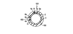
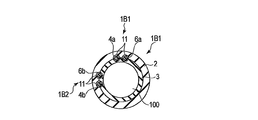
- FIG. 2 is a perspective view schematically showing a state in which the first elastic member 2 of the bending sensor 1 is removed.
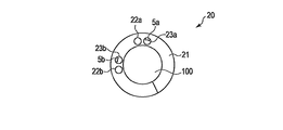
- FIG. 3 is a cross-sectional view of the bending sensor 1 taken along line AA in FIG.
- the bending sensor 1 includes a light supply fiber 4 as a light supply unit, a sensor fiber 6 as a bending measurement unit provided with a bending state detection unit 5, and a reflecting member 7 as a light transmission unit.
- the light supply fiber 4, the sensor fiber 6, and the reflection member 7 are inserted between the first elastic member 2 and the second elastic member 3, and the elasticity of the first and second elastic members 2, 3. It is clamped and fixed by force. Furthermore, you may fix with the adhesive agent which is not shown in figure.
- the light supply fiber 4 and the sensor fiber 6 are, for example, optical fibers composed of a glass core and a resin cladding.
- the bending state detection unit 5 is provided with, for example, a notch in a clad at a predetermined position of the sensor fiber 6, and a resin having desired optical characteristics (for example, an absorber or a fluorescent material that absorbs light of a specific wavelength). Body).
- the reflection member 7 is disposed on the front end side in the longitudinal direction of the light supply fiber 4 and the sensor fiber 6, and reflects the light guided from the light supply fiber 4 to the sensor fiber 6. That is, the light supply fiber 4 and the sensor fiber 6 are optically connected via the reflecting member 7.
- the reflecting member 7 is, for example, a prism that is a member that is composed of two orthogonal mirrors and reverses the direction of light by 180 °.
- a light source 8 is connected to the base end side in the longitudinal direction of the light supply fiber 4.
- the light source 8 is, for example, a laser light source, and emits laser light having a predetermined wavelength to the light supply fiber 4.
- a photodetector 9 is connected to the proximal end side of the sensor fiber 6 in the longitudinal direction.
- the photodetector 9 receives the light guided through the light supply fiber 4, reflected by the reflecting member 7, and guided through the sensor fiber 6. That is, the photodetector 9 is a light receiving unit that receives an optical signal (curved signal) related to the curved state from the sensor fiber 6.
- 1 to 3 show two light supply fibers 4a and 4b, two sensor fibers 6a and 6b provided with curved state detection sections 5a and 5b, respectively, and two reflecting members 7a and 7b. It is shown.
- Light sources 8a and 8b are connected to the proximal ends of the light supply fibers 4a and 4b, respectively.
- photodetectors 9a and 9b are connected to the proximal ends of the sensor fibers 6a and 6b, respectively.
- the bending state detection unit 5 a and the bending state detection unit 5 b are located at positions orthogonal to each other in the radial direction of the bending sensor 1, that is, in the direction of the center line O of the cylindrical body 1 ⁇ / b> A of the bending sensor 1. In the plane orthogonal to each other, they are arranged in the X-axis direction and the Y-axis direction orthogonal to the center line O, and detect a vertical curve and a horizontal curve, respectively. That is, the bending sensor 1 can measure the bending in the biaxial directions orthogonal to each other by the bending state detection units 5a and 5b.
- the positional relationship between the bending state detection unit 5a and the bending state detection unit 5b is not limited to 90 °, and the bending state detection units 5a and 5b are arranged in a positional relationship other than 90 °. Also good. Further, for example, only the bending state detection unit 5a may be configured to measure bending in one axis direction.
- the bent measuring object 100 When detecting the bending state of the bent measuring object 100, first, the bent measuring object 100 is inserted inside the second elastic member 3 of the bending sensor 1, and the first and second elastic members are inserted.
- the bending sensor 1 is attached to the outer peripheral surface of the measurement object 100 that is bent by a few elastic forces.
- the first and second elastic members 2, 3 hold the bending detection mechanism including the light supply fiber 4, the sensor fiber 6, and the reflection member 7 at a predetermined position on the measurement object 100 that bends ( It functions as a holding member.
- the light emitted from the light source 8 is guided through the light supply fiber 4, reflected by the reflecting member 7 disposed on the distal end side of the light supply fiber 4, and the reflected light is guided to the sensor fiber 6. Furthermore, when the reflected light passes through the bending state detection unit 5 of the sensor fiber 6, the amount of light leaking from the bending state detection unit 5 to the outside changes according to the bending angle and the bending direction. The changed amount of light is received by the photodetector 9 on the proximal end side of the sensor fiber 6. Thus, the bending state of the measurement object 100 to be bent in the vicinity of the bending state detection unit 5 is detected. In other words, the bending state of the object 100 to be bent can be measured by the change in the amount of light output through the bending state detection unit 5.
- the device under test 100 in which the sensor fiber 6 provided with the light supply fiber 4 and the bending state detection unit 5 is bent by the elastic force of the first elastic member 2 and the second elastic member 3. Held in place above.
- the bending detection mechanism including the bending state detection unit to the object to be bent, and to provide a bending sensor that can be mounted widely and generally even if the object to be measured has a relatively small diameter. can do.
- the curvature sensor of the present embodiment can be mounted not on the endoscope, such as an endoscope forceps channel, but on the outer peripheral surface of the endoscope. Therefore, even if the measurement object to be bent does not include a through-hole extending in the longitudinal direction such as a forceps channel, the bending sensor can be easily incorporated into the measurement object to be bent.
- an endoscope provided with a forceps channel
- a bladder endoscope water is supplied / drained from the forceps channel to the bladder, and the bending state of the endoscope is monitored to grasp where the endoscope is facing the bladder. Work to do.
- the user can freely attach and detach the bending sensor to the existing object to be bent.
- the bending sensor can be retrofitted without purchasing another object to be bent again.
- the bending sensor can be detached from the measurement object to be bent by the user, that is, the holder can be attached to and detached from the measurement object to be bent. Therefore, the bending sensor can return to a state in which it does not have a measurement object to be bent, that is, there is an effect that the options of the user are expanded.
- the light supply unit and the bending measurement unit are held at predetermined positions of the holding unit regardless of whether the holding unit is attached to or detached from the measurement object to be bent.
- a bending sensor when a bending sensor is attached to a measuring object having a relatively small diameter, the thinner the measuring object to be bent, the more mechanical or optical to the bending due to the rigidity of the constituent members of the retrofitting bending sensor. Adverse effects cannot be ignored. According to the present embodiment, it is possible to provide a bending sensor that can be mounted without obstructing the bendability of a measured object having a relatively small diameter. Furthermore, the bending state detection unit can be appropriately protected by the first and second elastic members as the holding unit.
- a maker may attach a curvature sensor to the existing to-be-measured body previously, without leaving it to a user.
- the bending sensor may be fixed to a measurement object that bends with an adhesive, solder, or the like, so that the bending sensor cannot be attached to or detached from the measurement object to be bent.
- Such a configuration is preferable, for example, in consideration of the convenience of the user with respect to the measured object to be bent of the disposal or the ultra-small curved measured object.
- the cores of the light supply fiber 4 and the sensor fiber 6 are not limited to glass but may be made of resin. If these are made of resin, the elasticity of the fiber increases, so that the fiber tends to bend following the bending of the first elastic member 2 and the second elastic member 3. Therefore, when the bending sensor 1 is bent, it becomes difficult for the light supply fiber 4 and the sensor fiber 6 to inhibit the bending between the first elastic member 2 and the second elastic member 3. Thereby, it becomes easy to cope with a large bending angle.
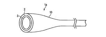
- FIG. 4 is a diagram schematically showing a curvature sensor 1a according to a first modification of the first embodiment.
- the bending sensor 1a has a tapered portion 10 on one end side.
- the tapered portion 10 gradually expands to a state in which the inner diameter increases as the first elastic member 2 and the second elastic member 3 move toward the end portion on one end side.
- the measured object 100 to be bent when the measured object 100 to be bent is inserted inside the second elastic member 3, the measured object 100 to be bent is guided to the expanded portion of the tapered portion 10. This facilitates the operation of inserting the measured object 100 to be bent inside the second elastic member 3.
- the tapered portion 10 may be provided not only on one end side of the bending sensor 1a but also on both end sides. Further, the tapered portion 10 may be cut on one end side of the first and second elastic members 2 and 3 so that the outer diameter of the tapered portion 10 does not become too large.
- the present invention is not limited to the tapered portion 10, and for example, a cut may be made at one end of each of the first and second elastic members 2 and 3 so that the one end is greatly elastically deformable. In this case as well, the work of inserting the measured object 100 to be curved inside the second elastic member 3 is facilitated.
- FIG. 5a and 5b are cross-sectional views showing a bending sensor 1b according to a second modification of the first embodiment.
- a thin circular elastic tube 11 is fixed between the first elastic member 2 and the second elastic member 3 with an adhesive (not shown).
- the light supply fibers 4 a and 4 b and the sensor fibers 6 a and 6 b are inserted through the elastic tube 11.
- the portions of the sensor fibers 6 a and 6 b where the detection unit 5 in the bent state is provided are not covered with the elastic tube 11.
- the inner diameter of the elastic tube 11 is larger than the outer diameters of the light supply fibers 4a and 4b and the sensor fibers 6a and 6b. Accordingly, the light supply fibers 4a and 4b and the sensor fibers 6a and 6b can slide in the elastic tube 11 in the optical axis direction (longitudinal direction) of the fiber.
- the elastic tube 11 does not extend to both ends of the first elastic member 2. Therefore, the light supply fibers 4a and 4b and the sensor fibers 6a and 6b are fixed to the first and second elastic members 2 and 3 by, for example, an adhesive at both ends thereof.
- the light supply fiber 4 and the sensor fiber 6 slide in the optical axis direction in the elastic tube 11, the light supply fiber 4 and the sensor fiber 6 are the first and second elastic members 2, 3. It is easy to bend following the curve. Therefore, it becomes difficult for the light supply fiber 4 and the sensor fiber 6 to inhibit the bending of the entire bending sensor 1b. Therefore, the bending sensor 1b can easily cope with a large bending angle.
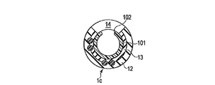
- FIG. 6 is a cross-sectional view showing a bending sensor 1c of a third modification of the first embodiment.
- the cross sections of the first and second elastic members 12 and 13 are not circular but C-shaped. That is, notches 14 are formed in the peripheral wall portions of the first and second elastic members 12 and 13.
- the notch 14 is formed in the first and second elastic members 12 and 13, so that the bending sensor 1c can be mounted from the side to the object to be bent. . For this reason, it is easy to attach the bending sensor 1c to the measurement object to be bent.
- This modification is particularly suitable when the elastic member is a metal spring material.
- the bending state detection unit 5 since the bending state detection unit 5 is disposed where the notch 14 is not provided, it is protected by the first and second elastic members 12 and 13 as the holding unit. Further, since the notches 14 are formed, the rigidity of the first and second elastic members 12 and 13 is reduced, and the bending is facilitated.
- the bending sensor 1c of the present modification is suitable for mounting on a measurement object having a smaller diameter than that of an endoscope, for example, a catheter punctured into a living tissue.
- FIG. 7 is a longitudinal sectional view schematically showing the catheter 101 to which the bending sensor 1c is attached.
- 8 is a cross-sectional view taken along the line CC of FIG.
- On the outer peripheral surface of the catheter 101 a through-hole 102 that penetrates the outer peripheral surface in the radial direction is formed.
- the through hole 102 is, for example, a discharge port for a drug or the like when a drug or the like is administered to a living tissue using the catheter 101 or a suction port for sucking a body fluid or the like from the living tissue.
- the cutouts 14 of the first and second elastic members 12 and 13 of the bending sensor 1c and the through-hole 102 of the catheter 101 are arranged so that the bending sensor 1c does not cover the through-hole 102 of the catheter 101.
- the bend sensor 1c is attached to the catheter 101 after alignment.
- the through hole 102 of the catheter 101 and the notch 14 of the curvature sensor 1c are aligned and mounted, so that the curvature sensor 1c of this modification can be attached to the catheter 101 without impeding the function of the catheter 101. Can be applied.
- FIG. 9 is a diagram schematically illustrating a bending sensor 1d according to a fourth modification of the first embodiment.
- the cylinder 1A is separated into a distal end side cylinder 15a and a proximal end side cylinder 15b. That is, the cylinders as holding members made of an elastic member are separated from each other.
- the bending state detection part 5 of the sensor fiber 6 is located in at least one of the front end side cylinder 15a and the base end side cylinder 15b.
- the distal end side cylinder 15a and the proximal end side cylinder 15b are connected by a light supply fiber 4 and a sensor fiber 6 that are sandwiched and fixed between them.
- an elastic member as a holding portion is not provided in a part of the light supply fiber 4 and the sensor fiber 6, for example, a portion of the sensor fiber 6 where the bending state detection unit 5 is not provided.
- the rigidity of the portion is reduced. Accordingly, the bending property of the bending sensor can be improved by the amount of reduced rigidity.
- the bending state detection unit is protected by the first and second elastic members as the holding unit.
- (Second Embodiment) 10 and 11 are diagrams showing the bending sensor 20 of the second embodiment.
- a part of the light supply fibers 4a and 4b in the first embodiment is replaced with light supply paths 22a and 22b formed of a core and a clad provided on the flexible optical wiring board 21.
- a part of the sensor fibers 6a and 6b including at least the bending state detection units 5a and 5b in the first embodiment is replaced with the sensor paths 23a and 23b formed of the core and the clad provided on the flexible optical wiring board 21.
- the light supply paths 22a and 22b and the light supply fibers 4a and 4b, and the sensor paths 23a and 23b and the sensor fibers 6a and 6b are optically coupled by fusion or the like.
- the first and second elastic members 2 and 3 in the first embodiment are unnecessary.
- the flexible optical wiring board 21 holds the bending detection mechanism including the bending state detection unit 5 at a predetermined position on the object 100 to be bent. It functions as a part.
- the flexible optical wiring board 21 In general, it is difficult to produce the flexible optical wiring board 21 long enough to accommodate the endoscope in the longitudinal direction (optical axis direction) of the bending sensor 20 (for example, a length of about 1 m) for reasons such as cost. is there. Therefore, as shown in FIG. 11, the light supply fibers 4a and 4b and the sensor fibers 6a and 6b are added to the flexible optical wiring board 21 as extension optical fibers. Thereby, even when the length of the flexible optical wiring board 21 is smaller than the required length, the length of the bending sensor 20 can be extended to the required length, which is advantageous in terms of cost and the like.
- the positional relationship between the two bending state detection units 5a and 5b is determined by the accuracy of the distance between the two sensor paths 23a and 23b of the flexible optical wiring board 21, the two sensor paths 23a, It is not necessary to align the position of 23b. Further, it is not necessary to match the positional relationship of the two bending state detection units 5a and 5b with respect to the circumferential direction of the bending sensor 20. Therefore, the assembly process of the bending sensor 20 can be simplified.
- the bending state detection unit is protected by the flexible optical wiring board.
- the flexible optical wiring board has a function of bundling the light supply path and the sensor path and a function of holding the light supply path and the sensor path with respect to the flexible optical wiring board. Since the flexible optical wiring board fulfills these two functions with a single member, it is not necessary to increase the number of components of the bending sensor. Therefore, the rigidity of the bending sensor can be reduced, and the bending of the bending sensor becomes easy.
- the core and the clad are made of resin, it becomes easy to provide a bending sensor with further improved bendability.
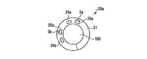
- FIG. 12 is a cross-sectional view showing a bending sensor 20a according to a modification of the second embodiment.
- the flexible optical wiring board 21 is not limited to a type using a light supply path and a sensor path of an optical fiber composed of a core and a clad.
- the flexible optical wiring board 21 is, for example, a flexible optical wiring board using light supply paths 24a and 24b made of optical waveguides and sensor paths 25a and 25b made of optical waveguides.
- the sensor paths 25a and 25b are respectively provided with bending state detection units 5a and 5b that are manufactured in advance at a part of the sensor paths 25a and 25b by printing or the like at the time of manufacture.
- FIG. 13 is a diagram schematically illustrating the bending sensor 30 of the third embodiment.
- the light supply fiber 4 and the sensor fiber 6 are configured by a single optical fiber. Therefore, the bending sensor 30 does not have the reflecting member 7 in the first embodiment, and is formed with folded portions 31 (31a, 31b) in which one optical fiber is bent in the middle thereof. That is, the folded portion 31 optically connects the light supply fiber 4 and the sensor fiber 6 without using the reflecting member 7.
- the present invention is not limited to this, and the bending sensor may be configured by a flexible optical wiring board in which the folded portion 31 is formed in advance.
- the present embodiment since there is no reflecting member, there is no reflection loss of light guided through the optical fiber, and a curved sensor with good sensitivity can be provided.
- the configuration of the bending sensor can be further simplified, it is easy to reduce the size and cost of the bending sensor.
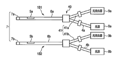
- (Fourth embodiment) 14 and 15 are diagrams showing a curvature sensor 40 of the fourth embodiment.
- the light supply fiber 4 and the sensor fiber 6 are connected by an optical coupler 41 (41a, 41b), and the light supply fiber 4 and the sensor fiber 6 become one optical fiber from the middle and are shared.
- a reflection member 7 (7a, 7b) is disposed on the tip side of the single sensor fiber 6 (6a, 6b).
- the light guided through the light supply fiber 4 passes through the optical coupler 41 and the sensor fiber 6, and the reflected light reflected by the reflecting member 7 guides the sensor fiber 6 and passes through the optical coupler 41.
- the light is received by the photodetector 9.
- the photodetector 9 measures the amount of light that reflects the amount of light that changes in the bending state detection unit 5 in accordance with the bending state of the sensor fiber 6, and detects the bending state.
- the light supply fiber and the sensor fiber are shared from the middle, and at least a part of the sensor fiber also serves as the light supply fiber, so that the number of fibers is reduced. This facilitates downsizing the curvature sensor. Moreover, since there are few fibers to use, it can manufacture at low cost. Further, the bending state detection unit is protected by first and second elastic members as holding units.
- the rigidity of the light supply fiber is difficult to prevent the measured object from bending. Furthermore, it is easy to realize a bending sensor corresponding to a large bending angle.
- FIG. 16 is a diagram schematically illustrating the second elastic member 51 of the bending sensor 50 according to the fifth embodiment.
- the second elastic member 51 of the bending sensor 50 includes a first region 52 and a second region 53 having different diameters.
- the first region 52 is formed by a small diameter portion having a first diameter r having a small diameter.
- the second region 53 is formed by a large diameter portion having a second diameter R (r ⁇ R) larger than the first diameter r.
- the first region 52 is a region where the bending state detection unit 5 of the sensor fiber 6 is disposed
- the second region 53 is a region where the bending state detection unit 5 is not disposed, that is, the bending state detection unit 5 and This is a region different from the region where is placed.
- the object to be measured which is inserted inside the second elastic member 51, is held with a stronger elastic force than the second region 53.
- the object to be measured is held with a relatively weak elastic force.
- the inner peripheral surface of the first elastic member engaged with the outer peripheral surface of the second elastic member 51 substantially conforms to the shape of the second outer peripheral surface, and the first and second elastic members A bending detection mechanism including a light supply fiber and a sensor fiber is sandwiched and fixed between the members.
- the curved state detection unit is provided with the region fixed by the relatively strong elastic force on the measurement object to bend, so that an accurate curved state can be measured, and at the same time, a large It is possible to easily cope with the bending angle.
- the optical fiber is held with a relatively weak elastic force, so that the optical fiber can slide in the area. For this reason, the curve is easy.
- FIG. 17 and 18 are views showing the first elastic member 61 of the bending sensor 60 of the sixth embodiment.
- the first elastic member 61 and the second elastic member are formed with at least one slit 63 penetrating the peripheral wall portions of these elastic members in the radial direction.
- the slits 63 are arranged at predetermined intervals in the circumferential direction of the first elastic member 61 and the second elastic member.
- the shape of the slit 63 is rectangular in FIG. 17, but may be circular, elliptical, or the like.
- the slit 63 is formed at a position different from the curved state detection unit 5 in the longitudinal direction of the first elastic member 61 and the second elastic member.
- the slit 63 may be provided only in one of the first elastic member 61 and the second elastic member.
- the slit is formed at a position different from the position where the bending state detection unit of the first and second elastic members is disposed (the position where the bending state detection unit is not provided).
- the rigidity of the elastic member becomes low and the bending becomes easy. Further, the bending state detection unit can be appropriately protected by the first and second elastic members.
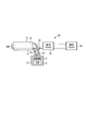
- FIG. 19 is a diagram schematically illustrating one aspect of the curvature sensor 70 of the seventh embodiment.
- the bending sensor 70 includes an optical fiber 71 that connects the light supply fiber 4 and the light source 8, and an optical fiber 72 that connects the sensor fiber 6 and the photodetector 9.
- the optical fibers 71 and 72 are connected to the first driver 75 by optical connectors 73 and 74, respectively.
- the first driver 75 is further connected to a second driver 76 including the light source 8 and the photodetector 9.
- the bending sensor can be easily mounted on the object to be bent.
- the bending sensor can be attached to and detached from the object to be bent with a connector, the bending state detection unit can be easily cleaned.
- FIG. 20 is a diagram schematically showing another aspect of the bending sensor 70 of the seventh embodiment.
- the optical fiber 71 and the optical fiber 72 may be bundled with a binding tool 78 on the way.
- the light source 8 and the photodetector 9 may be housed in a separate case 77.
- optical fibers are bundled, handling by the operator is easy. Moreover, in this aspect, it is not necessary to previously incorporate a light source or a light detector into the object to be bent, and a more versatile bending sensor can be provided.
- curve sensor DESCRIPTION OF SYMBOLS 41 ... Optical coupler, 50 ... Curve sensor, 51 ... 2nd elastic member, 52 ... 1st area
Abstract
比較的細径の湾曲する被測定体であっても広く一般的に適用することができる湾曲センサを提供する。本発明の一実施形態は、湾曲する被測定体の湾曲を測定する湾曲センサであって、光を導光する光供給部と、湾曲状態検出部を備え、湾曲状態検出部を通過して出力される光の光量の変化により被測定体の湾曲状態を測定可能とする湾曲測定部と、光供給部から湾曲測定部に光を伝達する光伝達部と、光供給部及び湾曲測定部を被測定体上の所定の位置に保持する保持部と、を具備する。
Description
本発明は、湾曲する被測定体の湾曲状態を検出する湾曲センサに関する。
一般的に、湾曲する被測定体の湾曲状態(湾曲角度や湾曲方向)を検出する湾曲センサが知られている。このような湾曲センサは、例えば、湾曲状態検出部を備えた光ファイバに光源から所定の光学特性を有する光を出射して導光する。このとき、湾曲状態検出部の光量が、光ファイバの湾曲角度や湾曲方向に対応して変化する。この光量の変化に基づいて、光ファイバの、延いては湾曲する被測定体の湾曲状態が検出される。
このような湾曲センサの一例として、特許文献1には、内視鏡の挿入管の形状を検出する内視鏡挿入形状検出プローブが開示されている。このプローブは、プローブ本体と、プローブ本体に接続されたモジュールとを有する。プローブ本体の外径は、内視鏡の鉗子チャンネルの内径未満に形成されている。プローブ本体は、光供給用ファイバと、光損失部が設けられた曲率検出用ファイバと、光供給用ファイバ及び曲率検出用ファイバの先端に配置されたミラーとを有している。
内視鏡の挿入形状を検出する際には、まず、プローブ本体が内視鏡の鉗子チャンネル内に挿入される。そして、光源から出射された光が、光供給用ファイバを導光し先端のミラーで反射する。その後、反射された光が曲率検出用ファイバを導光し、その基端からモジュール側で受光される。曲率検出用ファイバを導光された光は、光損失部で光が外部に漏れることによりその光量が変化しており、モジュール側で受光された光の光量に基づいて光損失部における曲率検出用ファイバの湾曲角度や湾曲方向が検出される。これにより、プローブ本体が挿入された内視鏡の挿入形状が検出される。
特許文献1に記載された内視鏡挿入形状検出プローブでは、内視鏡の鉗子チャンネル内にプローブ本体を挿入して内視鏡の挿入形状を検出する。従って、内部にチャンネルのような長手方向に延伸した貫通孔が設けられていない内視鏡には適用することができない。つまり、このようなプローブを広く一般的な湾曲する被測定体に組み込むことは困難である。また、カテーテルなどの比較的細径の被測定体にこのようなプローブを組み込むことも困難である。
そこで、本発明は、比較的細径の被測定体であっても広く一般的に適用することができる湾曲センサを提供することを目的とする。
本発明の一実施形態は、湾曲する被測定体の湾曲を測定する湾曲センサであって、光を導光する光供給部と、湾曲状態検出部を備え、前記湾曲状態検出部を通過して出力される光の光量の変化により前記被測定体の湾曲状態を測定する湾曲測定部と、前記光供給部から前記湾曲測定部に光を伝達する光伝達部と、前記光供給部及び前記湾曲測定部を前記被測定体上の所定の位置に保持する保持部と、を具備する湾曲センサである。
本発明によれば、湾曲する被測定体が比較的細径であっても広く一般的に適用することができる湾曲センサを提供することができる。
以下、本発明の実施形態について、図面を参照して説明する。
(第1の実施形態)
図1は、第1の実施形態の湾曲センサ1を概略的に示す図である。湾曲センサ1は、1つの円筒状の筒体1Aと、2つのセンサユニット1B1、1B2とを有している。筒体1Aは、円筒状の第1の弾性部材2及び円筒状の第2の弾性部材3を有している。第1の弾性部材2の内径は、第2の弾性部材3の外径と略同径に設定されている。第2の弾性部材3の外側に第2の弾性部材3が外嵌される状態で係合され、第1の弾性部材2の内周面に第2の弾性部材3の外周面が接合されている。第2の弾性部材3の内側には、湾曲する被測定体100、例えば、可撓湾曲部を有する軟性内視鏡、鉗子あるいはカテーテルが挿入される。第2の弾性部材3の内径は、挿入される被測定体100の外径に略適合するように設定されている。
図1は、第1の実施形態の湾曲センサ1を概略的に示す図である。湾曲センサ1は、1つの円筒状の筒体1Aと、2つのセンサユニット1B1、1B2とを有している。筒体1Aは、円筒状の第1の弾性部材2及び円筒状の第2の弾性部材3を有している。第1の弾性部材2の内径は、第2の弾性部材3の外径と略同径に設定されている。第2の弾性部材3の外側に第2の弾性部材3が外嵌される状態で係合され、第1の弾性部材2の内周面に第2の弾性部材3の外周面が接合されている。第2の弾性部材3の内側には、湾曲する被測定体100、例えば、可撓湾曲部を有する軟性内視鏡、鉗子あるいはカテーテルが挿入される。第2の弾性部材3の内径は、挿入される被測定体100の外径に略適合するように設定されている。
湾曲センサ1を湾曲する被測定体100に装着する際には、第2の弾性部材3の内周面が湾曲する被測定体100の外周面に接合される。このとき、第1及び第2の弾性部材2、3の弾性力によって湾曲センサ1が湾曲する被測定体100の外周面に保持され、固定される。
図2は、湾曲センサ1の第1の弾性部材2を取り除いた状態を概略的に示す斜視図である。図3は、図1のA-A線における湾曲センサ1の横断面図である。湾曲センサ1は、光供給部としての光供給ファイバ4と、湾曲状態検出部5が設けられた湾曲測定部としてのセンサファイバ6と、光伝達部としての反射部材7とを有している。光供給ファイバ4、センサファイバ6及び反射部材7は、第1の弾性部材2と第2の弾性部材3との間に挿入された状態で、第1及び第2の弾性部材2、3の弾性力によって挟持され、固定されている。さらに、図示しない接着剤で固定されてもよい。
光供給ファイバ4及びセンサファイバ6は、例えば、ガラス製のコアと樹脂製のクラッドとからなる光ファイバである。湾曲状態検出部5は、例えば、センサファイバ6の所定の位置のクラッドに切り欠きを設け、この切り欠きに所望の光学特性を有する樹脂(例えば、特定の波長の光を吸収する吸収体あるいは蛍光体)を充填することにより形成されている。
反射部材7は、光供給ファイバ4及びセンサファイバ6の長手方向先端側に配置され、光供給ファイバ4から導光された光をセンサファイバ6に反射させる。即ち、光供給ファイバ4とセンサファイバ6とは、反射部材7を介して光学的に接続されている。反射部材7は、例えば、プリズムで、直交した2枚のミラーからなり光の向きを180°反転させる部材である。
光供給ファイバ4の長手方向基端側には、光源8が接続されている。光源8は、例えば、レーザ光源であり、所定の波長のレーザ光を光供給ファイバ4に出射する。また、センサファイバ6の長手方向基端側には、光検出器9が接続されている。光検出器9は、光供給ファイバ4を導光され、反射部材7で反射され、センサファイバ6を導光された光を受光する。つまり、光検出器9は、センサファイバ6から湾曲状態に関する光信号(湾曲信号)を受信する受光部である。
図1乃至図3には、2本の光供給ファイバ4a、4bと、湾曲状態検出部5a、5bがそれぞれ設けられた2本のセンサファイバ6a、6bと、2つの反射部材7a、7bとが示されている。光供給ファイバ4a、4bの基端側には、それぞれ、光源8a、8bが接続されている。また、センサファイバ6a、6bの基端側には、それぞれ、光検出器9a、9bが接続されている。
湾曲状態検出部5aと湾曲状態検出部5bとは、図3に示すように、湾曲センサ1の径方向で互いに直交する位置に、即ち、湾曲センサ1の筒体1Aの中心線Oの方向に対して直交する平面内で、中心線Oを中心に直交するX軸方向とY軸方向とに配置されており、それぞれ、上下方向の湾曲と左右方向の湾曲とを検出する。即ち、湾曲センサ1は、湾曲状態検出部5a、5bにより直交する2軸方向の湾曲を測定可能である。
しかしながら、本実施形態は湾曲状態検出部5aと湾曲状態検出部5bとの位置関係が90°に限定されるものでなく、湾曲状態検出部5a、5bが90°以外の位置関係で配置されてもよい。また、例えば、湾曲状態検出部5aのみ構成され、1軸方向の湾曲を測定する構成であってもよい。
湾曲する被測定体100の湾曲状態を検出する際には、まず、湾曲センサ1の第2の弾性部材3の内側に湾曲する被測定体100を挿入して、第1及び第2の弾性部材2、3の弾性力により湾曲する被測定体100の外周面に湾曲センサ1を装着する。つまり、第1及び第2の弾性部材2、3が、光供給ファイバ4、センサファイバ6及び反射部材7を含む湾曲検出機構を湾曲する被測定体100上の所定の位置に保持する保持部(保持部材)として機能する。
そして、光源8から出射された光が光供給ファイバ4を導光され、光供給ファイバ4の先端側に配置された反射部材7で反射され、反射光がセンサファイバ6に導光される。さらに、反射光がセンサファイバ6の湾曲状態検出部5を通過したとき、その湾曲角度や湾曲方向に応じて湾曲状態検出部5から外部に漏れる光の光量が変化する。その変化した光量が、センサファイバ6の基端側の光検出器9で受光される。かくして、湾曲状態検出部5近傍の湾曲する被測定体100の湾曲状態が検出される。つまり、湾曲状態検出部5を経て出力される光の光量の変化により、湾曲する被測定体100の湾曲状態が測定可能となっている。
本実施形態によれば、第1の弾性部材2と第2の弾性部材3との弾性力によって、光供給ファイバ4及び湾曲状態検出部5が設けられたセンサファイバ6が湾曲する被測定体100上の所定の位置に保持される。これにより、湾曲する被測定体に湾曲状態検出部を含む湾曲検出機構を容易に固定することができ、比較的細径の被測定体であっても広く一般的に装着可能な湾曲センサを提供することができる。
本実施形態の湾曲センサは、例えば、内視鏡の鉗子チャンネルなどの内視鏡の内部ではなく、内視鏡の外周面に装着することができる。従って、湾曲する被測定体が鉗子チャンネルなどの長手方向に延伸した貫通孔を備えていなくても、湾曲する被測定体に湾曲センサを容易に組み込むことができる。
また、例えば、鉗子チャンネルを備えた内視鏡において、鉗子チャンネルで作業をしつつ内視鏡の湾曲状態をモニタする必要のある場合がある。このような作業の一例として、膀胱用内視鏡において、鉗子チャンネルから膀胱に給水/排水しつつ、内視鏡が膀胱のどこを向いているのか把握するために内視鏡の湾曲状態をモニタする作業が挙げられる。このような場合にも、鉗子チャンネルとは関係なく、湾曲センサを湾曲する被測定体に装着して湾曲する被測定体の湾曲状態を検出することができる。つまり、鉗子チャンネルを使って作業をしながら、湾曲する被測定体の湾曲状態を容易に検出することができる。
なお、本実施形態では、既存の湾曲する被測定体にユーザが湾曲センサを自由に着脱することができることを想定している。この場合、ユーザが湾曲する被測定体を購入後、別の湾曲する被測定体を改めて購入し直すことなく、湾曲センサを後付けで装着することができるという効果を奏する。また、ユーザが湾曲する被測定体から湾曲センサを取り外すことができる、つまり保持部が湾曲する被測定体に対して着脱可能である。従って、湾曲センサが湾曲する被測定体を有さない状態に戻せる、つまりユーザの選択肢が広がるという効果を奏する。なお、光供給部及び湾曲測定部は、保持部の湾曲する被測定体に対する着脱に関わらず、保持部の所定の位置に保持される。
また、比較的細径の湾曲する被測定体に湾曲センサを装着する場合、湾曲する被測定体が細くなればなるほど、後付けの湾曲センサの構成部材の剛性等による湾曲への機械的あるいは光学的な悪影響が無視できなくなる。本実施形態によれば、比較的細径の湾曲する被測定体であっても、その湾曲性を阻害することなく装着することができる湾曲センサを提供することができる。さらに、湾曲状態検出部が保持部としての第1及び第2の弾性部材により適切に保護されることができる。
なお、本実施形態は、以上の説明に限定されるものではなく、ユーザに委ねず、メーカが予め既存の湾曲する被測定体に湾曲センサを取り付けてもよい。この場合、例えば、湾曲センサを接着剤、はんだなどで湾曲する被測定体に固定するなどして、湾曲センサが湾曲する被測定体に対して着脱できないようになっていてもよい。このような構成は、例えば、ディスポーザルの湾曲する被測定体や超小型の湾曲する被測定体に対するユーザの利便性を参酌したときに好ましい。
なお、光供給ファイバ4及びセンサファイバ6のコアは、ガラス製に限定されるものではなく、樹脂製であってもよい。これらが樹脂製であれば、ファイバの弾性が大きくなるため、ファイバが第1の弾性部材2と第2の弾性部材3との湾曲に追従して湾曲しやすくなる。従って、湾曲センサ1が湾曲した際に光供給ファイバ4とセンサファイバ6とが第1の弾性部材2と第2の弾性部材3との間で湾曲を阻害しにくくなる。これにより、大きな湾曲角度に対応しやすくなることができる。
(第1の実施形態の第1の変形例)
図4は、第1の実施形態の第1の変形例の湾曲センサ1aを概略的に示す図である。本変形例では、湾曲センサ1aは、一端側にテーパ形状部10を有している。テーパ形状部10は、第1の弾性部材2及び第2の弾性部材3が一端側の端末部に向かうにしたがってそれぞれ内径が大きくなる状態に徐々に拡開する。
図4は、第1の実施形態の第1の変形例の湾曲センサ1aを概略的に示す図である。本変形例では、湾曲センサ1aは、一端側にテーパ形状部10を有している。テーパ形状部10は、第1の弾性部材2及び第2の弾性部材3が一端側の端末部に向かうにしたがってそれぞれ内径が大きくなる状態に徐々に拡開する。
本変形例では、湾曲する被測定体100を第2の弾性部材3の内側に挿入する際に、湾曲する被測定体100がテーパ形状部10の拡開部分に案内される。これにより、湾曲する被測定体100を第2の弾性部材3の内側に挿入する作業が容易になる。
なお、テーパ形状部10は、湾曲センサ1aの一端側のみならず、両端側に設けられてもよい。また、テーパ形状部10の外径が大きくなりすぎないように、第1及び第2の弾性部材2、3の一端側でテーパ形状部10に切り込みが入っていてもよい。
また、テーパ形状部10に限定されず、例えば、第1及び第2の弾性部材2、3の一端に切り込みを入れて、その一端が大きく弾性変形しやすい構造にしてもよい。この場合も、湾曲する被測定体100を第2の弾性部材3の内側に挿入する作業が容易になる。
(第1の実施形態の第2の変形例)
図5a並びに図5bは、第1の実施形態の第2の変形例の湾曲センサ1bを示す横断面図である。本変形例では、第1の弾性部材2と第2の弾性部材3との間に細い円管状の弾性管11が図示しない接着剤で固定されている。光供給ファイバ4a、4b及びセンサファイバ6a、6bは、この弾性管11に挿通されている。図5aに示すように、センサファイバ6a、6bの湾曲状態の検出部5が設けられている部分は、弾性管11に被覆されていない。弾性管11の内径は、光供給ファイバ4a、4b及びセンサファイバ6a、6bの外径よりも大きい。従って、光供給ファイバ4a、4b及びセンサファイバ6a、6bは、弾性管11中をファイバの光軸方向(長手方向)に摺動可能である。
図5a並びに図5bは、第1の実施形態の第2の変形例の湾曲センサ1bを示す横断面図である。本変形例では、第1の弾性部材2と第2の弾性部材3との間に細い円管状の弾性管11が図示しない接着剤で固定されている。光供給ファイバ4a、4b及びセンサファイバ6a、6bは、この弾性管11に挿通されている。図5aに示すように、センサファイバ6a、6bの湾曲状態の検出部5が設けられている部分は、弾性管11に被覆されていない。弾性管11の内径は、光供給ファイバ4a、4b及びセンサファイバ6a、6bの外径よりも大きい。従って、光供給ファイバ4a、4b及びセンサファイバ6a、6bは、弾性管11中をファイバの光軸方向(長手方向)に摺動可能である。
なお、弾性管11は、第1の弾性部材2の両端まで延伸していない。従って、光供給ファイバ4a、4b及びセンサファイバ6a、6bは、その両端で、例えば接着剤により第1及び第2の弾性部材2、3に固定されている。
本変形例によれば、光供給ファイバ4及びセンサファイバ6が弾性管11中で光軸方向に摺動するため、光供給ファイバ4及びセンサファイバ6が第1及び第2の弾性部材2、3の湾曲に追従して湾曲しやすい。従って、光供給ファイバ4及びセンサファイバ6が湾曲センサ1b全体の湾曲を阻害しにくくなる。それ故、湾曲センサ1bは、大きな湾曲角度に対応しやすくなることができる。
(第1の実施形態の第3の変形例)
図6は、第1の実施形態の第3の変形例の湾曲センサ1cを示す横断面図である。本変形例では、第1及び第2の弾性部材12、13の横断面が、円形ではなくC形状である。即ち、第1及び第2の弾性部材12、13の周壁部には、切り欠き14が形成されている。
図6は、第1の実施形態の第3の変形例の湾曲センサ1cを示す横断面図である。本変形例では、第1及び第2の弾性部材12、13の横断面が、円形ではなくC形状である。即ち、第1及び第2の弾性部材12、13の周壁部には、切り欠き14が形成されている。
本変形例によれば、第1及び第2の弾性部材12、13に切り欠き14が形成されていることにより、湾曲する被測定体に対して側部から湾曲センサ1cを装着することができる。このため、湾曲センサ1cが湾曲する被測定体に装着しやすい。本変形例は、弾性部材が金属製のばね材のときなどに特に適している。
また、本変形例においても、湾曲状態検出部5が切り欠き14のないところに配置されているため、保持部としての第1及び第2の弾性部材12、13により保護されている。また、切り欠き14が形成されていることにより、第1及び第2の弾性部材12、13の剛性が小さくなり、湾曲が容易になる。
本変形例の湾曲センサ1cは、内視鏡よりも細径の湾曲する被測定体、例えば、生体組織内に穿刺されるカテーテルへの装着に適している。図7は、湾曲センサ1cが装着されたカテーテル101を概略的に示す縦断面図である。図8は、図7のC-C線における横断面図である。カテーテル101の外周面には、外周面を径方向に貫通している貫通孔102が形成されている。貫通孔102は、例えば、カテーテル101を用いて薬剤等を生体組織に投与する際の薬剤等の吐出口、あるいは、生体組織から体液等を吸引する際の吸引口である。
装着の際には、カテーテル101の貫通孔102を湾曲センサ1cが覆わないように、湾曲センサ1cの第1及び第2の弾性部材12、13の切り欠き14とカテーテル101の貫通孔102とを位置合わせして、カテーテル101に湾曲センサ1cを装着する。
このように、カテーテル101の貫通孔102と湾曲センサ1cの切り欠き14とを位置合わせして装着することにより、カテーテル101の機能を阻害することなく、カテーテル101に本変形例の湾曲センサ1cを適用することができる。
(第1の実施形態の第4の変形例)
図9は、第1の実施形態の第4の変形例の湾曲センサ1dを概略的に示す図である。本変形例では、筒体1Aが、先端側筒体15aと基端側筒体15bとに分離されている。つまり、弾性部材からなる保持部材としての筒体が、互いに離間されている。センサファイバ6の湾曲状態検出部5は、先端側筒体15aと基端側筒体15bとの少なくとも一方に位置されている。先端側筒体15aと基端側筒体15bとは、これらに挟持され固定されている光供給ファイバ4及びセンサファイバ6により連結されている。
図9は、第1の実施形態の第4の変形例の湾曲センサ1dを概略的に示す図である。本変形例では、筒体1Aが、先端側筒体15aと基端側筒体15bとに分離されている。つまり、弾性部材からなる保持部材としての筒体が、互いに離間されている。センサファイバ6の湾曲状態検出部5は、先端側筒体15aと基端側筒体15bとの少なくとも一方に位置されている。先端側筒体15aと基端側筒体15bとは、これらに挟持され固定されている光供給ファイバ4及びセンサファイバ6により連結されている。
本変形例によれば、光供給ファイバ4及びセンサファイバ6の一部、例えば、センサファイバ6の湾曲状態検出部5が設けられていない部分には保持部としての弾性部材が設けられていないため、その部分の剛性が小さくなる。従って、剛性が小さくなった分、湾曲センサの湾曲性を向上させることができる。また、本変形例においても、湾曲状態検出部は保持部としての第1及び第2の弾性部材により保護されている。
以下、本発明の第2乃至第7の実施形態について説明する。以下の説明では、第1の実施形態と同様の構成部材には同じ参照符号を付し、その説明を省略する。
(第2の実施形態)
図10並びに図11は、第2の実施形態の湾曲センサ20を示す図である。本実施形態では、第1の実施形態における光供給ファイバ4a、4bの一部が、フレキシブル光配線板21に設けられたコアとクラッドとからなる光供給路22a、22bに置き換わっている。また、第1の実施形態における少なくとも湾曲状態検出部5a、5bを含むセンサファイバ6a、6bの一部が、フレキシブル光配線板21に設けられたコアとクラッドとからなるセンサ路23a、23bに置き換わっている。なお、光供給路22a、22bと光供給ファイバ4a、4bとの間、及びセンサ路23a、23bとセンサファイバ6a、6bとの間は、それぞれ、融着等により光学的に結合されている。
図10並びに図11は、第2の実施形態の湾曲センサ20を示す図である。本実施形態では、第1の実施形態における光供給ファイバ4a、4bの一部が、フレキシブル光配線板21に設けられたコアとクラッドとからなる光供給路22a、22bに置き換わっている。また、第1の実施形態における少なくとも湾曲状態検出部5a、5bを含むセンサファイバ6a、6bの一部が、フレキシブル光配線板21に設けられたコアとクラッドとからなるセンサ路23a、23bに置き換わっている。なお、光供給路22a、22bと光供給ファイバ4a、4bとの間、及びセンサ路23a、23bとセンサファイバ6a、6bとの間は、それぞれ、融着等により光学的に結合されている。
第2の実施形態では、第1の実施形態における第1及び第2の弾性部材2、3は不要である。湾曲センサ20を湾曲する被測定体100に装着する際には、フレキシブル光配線板21が、湾曲する被測定体100上の所定の位置に湾曲状態検出部5を含む湾曲検出機構を保持する保持部として機能する。
一般的に、フレキシブル光配線板21を湾曲センサ20の長手方向(光軸方向)に内視鏡に対応できるぐらい長く(例えば、1m程度の長さ)作製することはコスト等の理由により困難である。このため、図11に示すように、光供給ファイバ4a、4b及びセンサファイバ6a、6bを延長用光ファイバとしてフレキシブル光配線板21に付け足して製作する。これにより、フレキシブル光配線板21の長さが必要な長さよりも小さい場合でも湾曲センサ20の長さを必要な長さに延長することができ、コスト等で有利な構成となる。
本実施形態によれば、2つの湾曲状態検出部5a、5bの位置関係がフレキシブル光配線板21の2つのセンサ路23a、23b間の間隔精度により決定するため、組立時に2つのセンサ路23a、23bの位置を合わせる必要がなくなる。また、湾曲センサ20の周方向に対する2つの湾曲状態検出部5a、5bの位置関係を合わせる必要もなくなる。従って、湾曲センサ20の組立工程を簡略化することができる。
また、本実施形態においても、湾曲状態検出部はフレキシブル光配線板により保護されている。フレキシブル光配線板は、光供給路及びセンサ路を束ねる機能とフレキシブル光配線板に対して光供給路及びセンサ路を保持する機能とを有する。フレキシブル光配線板は、1つの部材でこれら2つの機能を果すため、湾曲センサの構成部材を増やさずに済む。従って、湾曲センサの剛性を小さくすることができ、湾曲センサの湾曲が容易となる。
なお、コア及びクラッドが樹脂製であれば、湾曲性のさらに向上した湾曲センサを提供しやすくなる。
(第2の実施形態の変形例)
図12は、第2の実施形態の変形例の湾曲センサ20aを示す横断面図である。本変形例では、フレキシブル光配線板21は、コアとクラッドとからなる光ファイバの光供給路及びセンサ路を用いたタイプに限定されない。フレキシブル光配線板21は、例えば、光導波路からなる光供給路24a、24bと、光導波路からなるセンサ路25a、25bとを用いたフレキシブル光配線板である。センサ路25a、25bには、それぞれ、製造時に予め印刷などによりセンサ路25a、25bの一部に製造された湾曲状態検出部5a、5bが設けられている。
図12は、第2の実施形態の変形例の湾曲センサ20aを示す横断面図である。本変形例では、フレキシブル光配線板21は、コアとクラッドとからなる光ファイバの光供給路及びセンサ路を用いたタイプに限定されない。フレキシブル光配線板21は、例えば、光導波路からなる光供給路24a、24bと、光導波路からなるセンサ路25a、25bとを用いたフレキシブル光配線板である。センサ路25a、25bには、それぞれ、製造時に予め印刷などによりセンサ路25a、25bの一部に製造された湾曲状態検出部5a、5bが設けられている。
本変形例においても、湾曲性の向上した湾曲センサを提供することができる。また、湾曲状態検出部はフレキシブル光配線板により保護されている。
(第3の実施形態)
図13は、第3の実施形態の湾曲センサ30を概略的に示す図である。本実施形態では、光供給ファイバ4及びセンサファイバ6は、1本の光ファイバにより構成されている。従って、湾曲センサ30には第1の実施形態における反射部材7がなく、1本の光ファイバをその途中で屈曲させた折り返し部31(31a、31b)が形成されている。つまり、反射部材7を介さずに、折り返し部31が光供給ファイバ4とセンサファイバ6とを光学的に接続している。
図13は、第3の実施形態の湾曲センサ30を概略的に示す図である。本実施形態では、光供給ファイバ4及びセンサファイバ6は、1本の光ファイバにより構成されている。従って、湾曲センサ30には第1の実施形態における反射部材7がなく、1本の光ファイバをその途中で屈曲させた折り返し部31(31a、31b)が形成されている。つまり、反射部材7を介さずに、折り返し部31が光供給ファイバ4とセンサファイバ6とを光学的に接続している。
なお、これに限定されず、予め折り返し部31を形成したフレキシブル光配線板により湾曲センサを構成してもよい。
本実施形態によれば、反射部材がないため、光ファイバを導光する光の反射ロスがなく、その分感度の良い湾曲センサを提供することができる。また、湾曲センサの構成をより簡略化することができるので、湾曲センサの小型化、安価化が容易になる。
(第4の実施形態)
図14並びに図15は、第4の実施形態の湾曲センサ40を示す図である。本実施形態では、光供給ファイバ4とセンサファイバ6とは、光カプラ41(41a、41b)で接続されており、光供給ファイバ4とセンサファイバ6とはその途中から1本の光ファイバとなり共用されている。1本となったセンサファイバ6(6a、6b)の先端側には、反射部材7(7a、7b)が配置されている。
図14並びに図15は、第4の実施形態の湾曲センサ40を示す図である。本実施形態では、光供給ファイバ4とセンサファイバ6とは、光カプラ41(41a、41b)で接続されており、光供給ファイバ4とセンサファイバ6とはその途中から1本の光ファイバとなり共用されている。1本となったセンサファイバ6(6a、6b)の先端側には、反射部材7(7a、7b)が配置されている。
本実施形態では、光供給ファイバ4を導光する光は光カプラ41を通ってセンサファイバ6を導光し、さらに反射部材7で反射された反射光がセンサファイバ6を導光し光カプラ41を通って光検出器9で受光される。光検出器9は、センサファイバ6の湾曲状態に応じて湾曲状態検出部5で変化する光の光量を反映した光量を測定し、湾曲状態を検出する。
本実施形態によれば、光供給ファイバとセンサファイバとが途中から共用となり、センサファイバの少なくとも一部が光供給ファイバを兼ねているため、ファイバの本数が少なくなる。これにより、湾曲センサの小型化が容易となる。また、使用するファイバが少ないため、安価に製造することができる。さらに、湾曲状態検出部が保持部としての第1及び第2の弾性部材により保護されている。
また、光供給ファイバが湾曲する被測定体と接触しないため、光供給ファイバの剛性が湾曲する被測定体の湾曲を妨げにくくなる。さらに、大きな湾曲角度に対応した湾曲センサを実現するのが容易である。
(第5の実施形態)
図16は、第5の実施形態の湾曲センサ50の第2の弾性部材51を概略的に示す図である。本実施形態では、湾曲センサ50の第2の弾性部材51が、互いに異なる径を備えた第1の領域52と第2の領域53とを有する。第1の領域52は、小径な第1の径rを備えた小径部により形成されている。第2の領域53は、第1の径rよりも大径な第2の径R(r<R)を備えた大径部により形成されている。
図16は、第5の実施形態の湾曲センサ50の第2の弾性部材51を概略的に示す図である。本実施形態では、湾曲センサ50の第2の弾性部材51が、互いに異なる径を備えた第1の領域52と第2の領域53とを有する。第1の領域52は、小径な第1の径rを備えた小径部により形成されている。第2の領域53は、第1の径rよりも大径な第2の径R(r<R)を備えた大径部により形成されている。
第1の領域52は、センサファイバ6の湾曲状態検出部5が配置される領域であり、また、第2の領域53は、湾曲状態検出部5が配置されない領域、即ち湾曲状態検出部5とが配置される領域とは異なる領域である。第1の領域52では、第2の弾性部材51の内側に挿入される湾曲する被測定体を第2の領域53よりも強い弾性力で保持する。第2の領域53では、湾曲する被測定体を比較的弱い弾性力で保持する。
なお、図示しないが、第2の弾性部材51の外周面に係合される第1の弾性部材の内周面は、第2の外周面の形状に略適合し、第1及び第2の弾性部材の間に光供給ファイバ、センサファイバ等を含む湾曲検出機構を挟持し固定するように構成されている。
本実施形態によれば、湾曲状態検出部が湾曲する被測定体に比較的強い弾性力で固定される領域が設けられていることにより、正確な湾曲状態を測定することができ、同時に、大きな湾曲角度に容易に対応することができる。
また、湾曲状態検出部が設けられていない領域では、比較的弱い弾性力で光ファイバが保持されているので、当該領域で光ファイバが摺動可能である。このため、湾曲が容易である。
(第6の実施形態)
図17並びに図18は、第6の実施形態の湾曲センサ60の第1の弾性部材61を示す図である。本実施形態では、第1の弾性部材61及び第2の弾性部材には、これら弾性部材の周壁部を径方向に貫通している少なくとも1つのスリット63が形成されている。スリット63は、例えば、第1の弾性部材61及び第2の弾性部材の周方向に所定の間隔で配置されている。スリット63の形状は、図17では矩形であるが、円形、楕円形などであってもよい。
図17並びに図18は、第6の実施形態の湾曲センサ60の第1の弾性部材61を示す図である。本実施形態では、第1の弾性部材61及び第2の弾性部材には、これら弾性部材の周壁部を径方向に貫通している少なくとも1つのスリット63が形成されている。スリット63は、例えば、第1の弾性部材61及び第2の弾性部材の周方向に所定の間隔で配置されている。スリット63の形状は、図17では矩形であるが、円形、楕円形などであってもよい。
図17並びに図18には第1の弾性部材61のみを示すが、第2の弾性部材も同様に構成されている。スリット63は、第1の弾性部材61及び第2の弾性部材の長手方向において、湾曲状態検出部5とは異なる位置に形成されている。スリット63は、第1の弾性部材61と第2の弾性部材との一方にのみ設けられていてもよい。
本実施形態によれば、第1及び第2の弾性部材の湾曲状態検出部が配置される位置とは異なる位置(湾曲状態検出部が設けられていない位置)にスリットが形成されていることにより、弾性部材の剛性が低くなり、湾曲が容易となる。また、湾曲状態検出部は第1及び第2の弾性部材により適切に保護されることができる。
(第7の実施形態)
図19は、第7の実施形態の湾曲センサ70の一態様を概略的に示す図である。本実施形態では、湾曲センサ70は、光供給ファイバ4と光源8とを接続する光ファイバ71と、センサファイバ6と光検出器9とをつなぐ光ファイバ72とを有している。光ファイバ71、72は、それぞれ、光コネクタ73、74によって第1のドライバ75に接続されている。第1のドライバ75は、さらに、光源8及び光検出器9を含む第2のドライバ76に接続されている。
図19は、第7の実施形態の湾曲センサ70の一態様を概略的に示す図である。本実施形態では、湾曲センサ70は、光供給ファイバ4と光源8とを接続する光ファイバ71と、センサファイバ6と光検出器9とをつなぐ光ファイバ72とを有している。光ファイバ71、72は、それぞれ、光コネクタ73、74によって第1のドライバ75に接続されている。第1のドライバ75は、さらに、光源8及び光検出器9を含む第2のドライバ76に接続されている。
本実施形態によれば、湾曲センサを湾曲する被測定体に容易に搭載することができる。また、湾曲センサが湾曲する被測定体にコネクタで着脱可能であるので、湾曲状態検出部の洗浄が容易である。
図20は、第7の実施形態の湾曲センサ70の他の態様を概略的に示す図である。本変形例のように、光ファイバ71と光ファイバ72とは、途中で結束具78で束ねられていてもよい。また、光源8及び光検出器9は、別体のケース77に収容されていてもよい。
光ファイバが束ねられていれば、作業者による取り扱いが容易である。また、本態様では、湾曲する被測定体に予め光源や光検出器を組み込んでおく必要がなく、汎用性のより高い湾曲センサを提供することができる。
以上、本発明の各実施形態並びに変形例について説明したが、本発明は、これらに限定されるものではなく、本発明の要旨を逸脱しない範囲でさまざまな改良及び変更が可能である。
1…湾曲センサ、2…第1の弾性部材、3…第2の弾性部材、4…光供給ファイバ、5…湾曲状態検出部、6…センサファイバ、7…反射部材、8…光源、9…光検出器、10…テーパ形状部、11…弾性管、12…第1の弾性部材、13…第2の弾性部材、14…切り欠き、15a…先端側筒体、15b…基端側筒体、20…湾曲センサ、21…フレキシブル光配線板、22…光供給路、23…センサ路、24…光供給路、25…センサ路、30…湾曲センサ、31…折り返し部、40…湾曲センサ、41…光カプラ、50…湾曲センサ、51…第2の弾性部材、52…第1の領域、53…第2の領域、60…湾曲センサ、61…第1の弾性部材、62…第2の弾性部材、63…スリット、70…湾曲センサ、71、72…光ファイバ、73、74…光コネクタ、75…第1のドライバ、76…第2のドライバ、77…ケース。
Claims (23)
- 湾曲する被測定体の湾曲を測定する湾曲センサであって、
光を導光する光供給部と、
湾曲状態検出部を備え、前記湾曲状態検出部を経て出力される光の光量の変化により前記被測定体の湾曲状態を測定可能とする湾曲測定部と、
前記光供給部から前記湾曲測定部に光を伝達する光伝達部と、
前記光供給部及び前記湾曲測定部を前記被測定体上の所定の位置に保持する保持部と、
を具備する湾曲センサ。 - 前記保持部は、円筒状の筒体であり、前記被測定体が前記筒体の内側に挿入される請求項1に記載の湾曲センサ。
- 前記保持部は、
円筒状の第1の保持部材と、
前記第1の保持部材の内周面に外周面が係合され、内側に前記被測定体が挿入される円筒状の第2の保持部材と、
を有し、
前記保持部は、前記第1の保持部材の内周面と前記第2の保持部材の外周面との間に、前記光供給部と前記湾曲測定部との少なくとも一方が挟持される構成である請求項2に記載の湾曲センサ。 - 前記保持部は、径が異なる第1の領域と第2の領域とを有し、
小径部により形成されている第1の領域には、前記湾曲測定部の前記湾曲状態検出部が設けられ、
大径部により形成されている第2の領域には、前記湾曲測定部における前記湾曲状態検出部とは異なる部分の少なくとも一部が摺動可能に挿通されている請求項3に記載の湾曲センサ。 - 前記保持部は、前記湾曲測定部の前記湾曲状態検出部が設けられた部分を前記湾曲状態検出部が設けられていない部分よりも強い力で前記被測定体に固定して保持する請求項3に記載の湾曲センサ。
- 前記第1及び第2の保持部材の周壁部の少なくとも一方には、径方向に貫通した少なくとも1つのスリットが形成され、
前記湾曲測定部の前記湾曲状態検出部が設けられた部分は、前記第1及び第2の保持部材の前記スリットが形成されていない部分に挟持されている請求項3に記載の湾曲センサ。 - 前記保持部は、互いに離間された複数の保持部材を有し、
前記複数の保持部材は、前記光供給部と前記湾曲測定部との少なくとも一方によって互いに連結されている請求項2に記載の湾曲センサ。 - 前記保持部は、弾性力により前記光供給部及び前記湾曲測定部を前記被測定体上の所定の位置に保持する弾性部材である請求項1に記載の湾曲センサ。
- 前記湾曲状態検出部は、前記保持部により保護されている請求項8に記載の湾曲センサ。
- 前記保持部は、前記被測定体に対して着脱可能である請求項8に記載の湾曲センサ。
- 前記光供給部及び前記湾曲測定部は、前記保持部の前記被測定体に対する着脱に関わらず、前記保持部の所定の位置に保持される請求項10に記載の湾曲センサ。
- 前記弾性部材は、
円筒状の第1の弾性部材と、
前記第1の弾性部材の内周面に外周面が係合され、内側に前記被測定体が挿入される円筒状の第2の弾性部材と、
を有し、
前記第1の弾性部材及び前記第2の弾性部材の周壁部には、前記被測定体への側部からの装着を可能とする切り欠きが形成されている請求項8に記載の湾曲センサ。 - 前記第1の弾性部材及び前記第2の弾性部材の少なくとも一端側には、前記少なくとも一端からの前記被測定体の挿入を容易とするテーパ形状部が設けられている請求項8に記載の湾曲センサ。
- 前記光供給部と前記湾曲測定部とは、1本の光ファイバからなり、
前記光伝達部は、前記光ファイバが屈曲した折り返し部である請求項2に記載の湾曲センサ。 - 前記湾曲測定部の少なくとも一部は、前記光供給部を兼ねている請求項2に記載の湾曲センサ。
- 少なくとも一部が前記光供給部を兼ねている前記湾曲測定部は、1本の光ファイバからなり、
所定の光学特性を有する光を出射する光源からの光を前記湾曲測定部に、及び前記湾曲測定部からの光を受光部に導光する光接続部をさらに具備し、
前記光ファイバの一端には、前記光接続部が接続され、
前記光ファイバの他端には、前記光ファイバ内の光を反射する反射部が前記光伝達部として形成されている請求項15に記載の湾曲センサ。 - 前記光供給部及び前記湾曲測定部の少なくとも一部は、フレキシブル光配線板からなる請求項15に記載の湾曲センサ。
- 前記保持部は、フレキシブル光配線板である請求項2に記載の湾曲センサ。
- 前記フレキシブル光配線板の少なくとも一方の端面に延長用光ファイバが接続されている請求項18に記載の湾曲センサ。
- 前記湾曲状態検出部は、印刷により前記フレキシブル光配線板に形成されている請求項18に記載の湾曲センサ。
- 前記湾曲測定部から湾曲状態に関する信号を受信する受光部と、前記光供給部に光を供給する光源とが、前記被測定体の外部に設けられた同一のケースに収容されている請求項2に記載の湾曲センサ。
- 前記湾曲測定部と前記湾曲測定部から湾曲状態に関する信号を受信する受光部とを接続する部材と、前記光供給部と前記光供給部に光を供給する光源とを接続する部材とが束ねられている請求項21に記載の湾曲センサ。
- 前記湾曲測定部から湾曲状態に関する信号を受信する受光部と、前記光供給部に光を供給する光源との少なくとも一方が、着脱可能なコネクタによって接続される請求項2に記載の湾曲センサ。
Priority Applications (3)
| Application Number | Priority Date | Filing Date | Title |
|---|---|---|---|
| CN201380027015.0A CN104334070B (zh) | 2012-06-20 | 2013-06-19 | 弯曲传感器 |
| EP13807866.2A EP2865317A4 (en) | 2012-06-20 | 2013-06-19 | CURVE DETECTOR |
| US14/570,176 US9766059B2 (en) | 2012-06-20 | 2014-12-15 | Curve sensor |
Applications Claiming Priority (2)
| Application Number | Priority Date | Filing Date | Title |
|---|---|---|---|
| JP2012138925A JP5963563B2 (ja) | 2012-06-20 | 2012-06-20 | 湾曲センサ |
| JP2012-138925 | 2012-06-20 |
Related Child Applications (1)
| Application Number | Title | Priority Date | Filing Date |
|---|---|---|---|
| US14/570,176 Continuation US9766059B2 (en) | 2012-06-20 | 2014-12-15 | Curve sensor |
Publications (1)
| Publication Number | Publication Date |
|---|---|
| WO2013191214A1 true WO2013191214A1 (ja) | 2013-12-27 |
Family
ID=49768808
Family Applications (1)
| Application Number | Title | Priority Date | Filing Date |
|---|---|---|---|
| PCT/JP2013/066869 WO2013191214A1 (ja) | 2012-06-20 | 2013-06-19 | 湾曲センサ |
Country Status (5)
| Country | Link |
|---|---|
| US (1) | US9766059B2 (ja) |
| EP (1) | EP2865317A4 (ja) |
| JP (1) | JP5963563B2 (ja) |
| CN (1) | CN104334070B (ja) |
| WO (1) | WO2013191214A1 (ja) |
Families Citing this family (9)
| Publication number | Priority date | Publication date | Assignee | Title |
|---|---|---|---|---|
| US9645570B2 (en) * | 2013-03-22 | 2017-05-09 | Pegatron Corporation | Monitoring system |
| TWI476554B (zh) * | 2013-03-22 | 2015-03-11 | Pegatron Corp | 監控系統 |
| CN107529940B (zh) * | 2015-04-10 | 2019-07-16 | 奥林巴斯株式会社 | 光纤传感器 |
| CN107613834B (zh) * | 2015-05-29 | 2019-08-02 | 奥林巴斯株式会社 | 曲率传感器和搭载有该曲率传感器的内窥镜装置 |
| JP2018018720A (ja) * | 2016-07-28 | 2018-02-01 | パナソニックIpマネジメント株式会社 | 発光装置、および、発光装置の点検方法 |
| DE102018105132B4 (de) * | 2018-03-06 | 2023-07-13 | Haag-Streit Gmbh | Triangulationsvorrichtung |
| US11214120B2 (en) * | 2018-11-02 | 2022-01-04 | Continental Automotive Systems, Inc. | Distributed fiber optic sensing system |
| CN110095086A (zh) * | 2019-06-03 | 2019-08-06 | 呜啦啦(广州)科技有限公司 | 电流式双向弯曲传感器及其制备方法 |
| CN111678465B (zh) * | 2020-05-28 | 2021-12-10 | 哈尔滨工业大学 | 一种基于超声导波的管道弯曲检测方法 |
Citations (4)
| Publication number | Priority date | Publication date | Assignee | Title |
|---|---|---|---|---|
| JPH0591972A (ja) * | 1991-10-02 | 1993-04-16 | Toshiba Corp | 湾曲表示装置 |
| JP2005027725A (ja) * | 2003-07-07 | 2005-02-03 | Olympus Corp | 超音波診断装置 |
| JP2007044405A (ja) * | 2005-08-12 | 2007-02-22 | Pentax Corp | 内視鏡挿入形状検出プローブ |
| JP2007044412A (ja) | 2005-08-12 | 2007-02-22 | Pentax Corp | 内視鏡挿入形状検出プローブ |
Family Cites Families (16)
| Publication number | Priority date | Publication date | Assignee | Title |
|---|---|---|---|---|
| AU6967094A (en) * | 1993-06-10 | 1995-01-03 | Lee A. Danisch | Fiber optic bending and positioning sensor |
| JP4005318B2 (ja) | 2001-02-28 | 2007-11-07 | ペンタックス株式会社 | 可撓性内視鏡装置 |
| JP3881526B2 (ja) | 2001-05-22 | 2007-02-14 | ペンタックス株式会社 | 可撓性内視鏡装置 |
| JP3881525B2 (ja) | 2001-05-22 | 2007-02-14 | ペンタックス株式会社 | 可撓性内視鏡装置 |
| JP3898910B2 (ja) | 2001-05-31 | 2007-03-28 | ペンタックス株式会社 | 可撓性内視鏡装置 |
| AU2003288565A1 (en) * | 2002-12-16 | 2004-07-09 | Aston Photonic Technologies Limited | Optical interrogation system and sensor system |
| DE102004017834B4 (de) * | 2004-04-13 | 2011-01-27 | Siemens Ag | Kathetereinrichtung |
| ATE433044T1 (de) * | 2004-08-27 | 2009-06-15 | Schlumberger Holdings | Sensor und vermessungsvorrichtung zur bestimmung des biegeradius und der form eines rohrleitungs |
| JP4714570B2 (ja) * | 2005-11-24 | 2011-06-29 | Hoya株式会社 | 内視鏡形状検出プローブ |
| US8989528B2 (en) * | 2006-02-22 | 2015-03-24 | Hansen Medical, Inc. | Optical fiber grating sensors and methods of manufacture |
| GB0620944D0 (en) * | 2006-10-20 | 2006-11-29 | Insensys Ltd | Curvature measurement moving relative to pipe |
| JP4580973B2 (ja) * | 2007-11-29 | 2010-11-17 | オリンパスメディカルシステムズ株式会社 | 処置具システム |
| US8886334B2 (en) * | 2008-10-07 | 2014-11-11 | Mc10, Inc. | Systems, methods, and devices using stretchable or flexible electronics for medical applications |
| JP4759654B2 (ja) * | 2008-10-28 | 2011-08-31 | オリンパスメディカルシステムズ株式会社 | 医療機器 |
| US9387048B2 (en) * | 2011-10-14 | 2016-07-12 | Intuitive Surgical Operations, Inc. | Catheter sensor systems |
| US9062960B2 (en) * | 2012-02-07 | 2015-06-23 | Medlumics S.L. | Flexible waveguides for optical coherence tomography |
-
2012
- 2012-06-20 JP JP2012138925A patent/JP5963563B2/ja not_active Expired - Fee Related
-
2013
- 2013-06-19 CN CN201380027015.0A patent/CN104334070B/zh active Active
- 2013-06-19 EP EP13807866.2A patent/EP2865317A4/en not_active Withdrawn
- 2013-06-19 WO PCT/JP2013/066869 patent/WO2013191214A1/ja unknown
-
2014
- 2014-12-15 US US14/570,176 patent/US9766059B2/en active Active
Patent Citations (4)
| Publication number | Priority date | Publication date | Assignee | Title |
|---|---|---|---|---|
| JPH0591972A (ja) * | 1991-10-02 | 1993-04-16 | Toshiba Corp | 湾曲表示装置 |
| JP2005027725A (ja) * | 2003-07-07 | 2005-02-03 | Olympus Corp | 超音波診断装置 |
| JP2007044405A (ja) * | 2005-08-12 | 2007-02-22 | Pentax Corp | 内視鏡挿入形状検出プローブ |
| JP2007044412A (ja) | 2005-08-12 | 2007-02-22 | Pentax Corp | 内視鏡挿入形状検出プローブ |
Non-Patent Citations (1)
| Title |
|---|
| See also references of EP2865317A4 |
Also Published As
| Publication number | Publication date |
|---|---|
| EP2865317A1 (en) | 2015-04-29 |
| JP5963563B2 (ja) | 2016-08-03 |
| US9766059B2 (en) | 2017-09-19 |
| US20150100000A1 (en) | 2015-04-09 |
| CN104334070B (zh) | 2017-03-15 |
| JP2014000312A (ja) | 2014-01-09 |
| CN104334070A (zh) | 2015-02-04 |
| EP2865317A4 (en) | 2016-03-02 |
Similar Documents
| Publication | Publication Date | Title |
|---|---|---|
| WO2013191214A1 (ja) | 湾曲センサ | |
| JP6270347B2 (ja) | 形状センサ | |
| US10307211B2 (en) | Multipoint detection fiber sensor and insertion apparatus including multipoint detection fiber sensor | |
| EP3032217A1 (en) | Optical sensor, optical sensor system, and endoscope | |
| US10064542B2 (en) | Bending apparatus with bending direction restriction mechanism | |
| WO2015163210A1 (ja) | 内視鏡装置 | |
| US10436578B2 (en) | Endoscope apparatus | |
| JP2007044412A (ja) | 内視鏡挿入形状検出プローブ | |
| JP6108844B2 (ja) | 形状センサ | |
| CN107250864B (zh) | 光纤电缆组件及测定装置 | |
| JP6461343B2 (ja) | 形状検出装置 | |
| JP6447038B2 (ja) | 光コネクタ結合システム | |
| CN106061352A (zh) | 内窥镜 | |
| KR20180012079A (ko) | 거리 확장과 온도 보상이 가능한 휴대용 광섬유 센서 시스템 | |
| WO2017208402A1 (ja) | 形状検出装置 | |
| JP2005188971A (ja) | 保持具、光学測定装置、及び光学測定方法 |
Legal Events
| Date | Code | Title | Description |
|---|---|---|---|
| 121 | Ep: the epo has been informed by wipo that ep was designated in this application |
Ref document number: 13807866 Country of ref document: EP Kind code of ref document: A1 |
|
| NENP | Non-entry into the national phase |
Ref country code: DE |