WO2013190825A1 - 衣類処理装置 - Google Patents
衣類処理装置 Download PDFInfo
- Publication number
- WO2013190825A1 WO2013190825A1 PCT/JP2013/003778 JP2013003778W WO2013190825A1 WO 2013190825 A1 WO2013190825 A1 WO 2013190825A1 JP 2013003778 W JP2013003778 W JP 2013003778W WO 2013190825 A1 WO2013190825 A1 WO 2013190825A1
- Authority
- WO
- WIPO (PCT)
- Prior art keywords
- steam
- water
- steam generator
- storage tank
- supply mechanism
- Prior art date
Links
- 238000011282 treatment Methods 0.000 title abstract description 3
- XLYOFNOQVPJJNP-UHFFFAOYSA-N water Substances O XLYOFNOQVPJJNP-UHFFFAOYSA-N 0.000 claims abstract description 233
- 230000007246 mechanism Effects 0.000 claims abstract description 55
- 238000010438 heat treatment Methods 0.000 claims abstract description 9
- 238000012545 processing Methods 0.000 claims description 17
- 239000000463 material Substances 0.000 claims description 4
- 229910052751 metal Inorganic materials 0.000 claims description 2
- 239000002184 metal Substances 0.000 claims description 2
- 230000015556 catabolic process Effects 0.000 abstract 1
- 238000006731 degradation reaction Methods 0.000 abstract 1
- 238000005406 washing Methods 0.000 description 45
- 230000002093 peripheral effect Effects 0.000 description 21
- 239000012535 impurity Substances 0.000 description 14
- 239000003599 detergent Substances 0.000 description 12
- 238000012856 packing Methods 0.000 description 8
- 230000000694 effects Effects 0.000 description 7
- 238000010586 diagram Methods 0.000 description 6
- 230000018044 dehydration Effects 0.000 description 5
- 238000006297 dehydration reaction Methods 0.000 description 5
- 230000005484 gravity Effects 0.000 description 5
- 230000002787 reinforcement Effects 0.000 description 5
- XEEYBQQBJWHFJM-UHFFFAOYSA-N Iron Chemical compound [Fe] XEEYBQQBJWHFJM-UHFFFAOYSA-N 0.000 description 4
- 239000000835 fiber Substances 0.000 description 4
- 238000009834 vaporization Methods 0.000 description 4
- 230000008016 vaporization Effects 0.000 description 4
- 230000007423 decrease Effects 0.000 description 3
- 230000006866 deterioration Effects 0.000 description 3
- 229910052739 hydrogen Inorganic materials 0.000 description 3
- 239000001257 hydrogen Substances 0.000 description 3
- 230000037303 wrinkles Effects 0.000 description 3
- 230000001154 acute effect Effects 0.000 description 2
- 229910052782 aluminium Inorganic materials 0.000 description 2
- XAGFODPZIPBFFR-UHFFFAOYSA-N aluminium Chemical compound [Al] XAGFODPZIPBFFR-UHFFFAOYSA-N 0.000 description 2
- 238000001816 cooling Methods 0.000 description 2
- 238000001035 drying Methods 0.000 description 2
- 238000001704 evaporation Methods 0.000 description 2
- 230000008020 evaporation Effects 0.000 description 2
- 238000003780 insertion Methods 0.000 description 2
- 230000037431 insertion Effects 0.000 description 2
- 229910052742 iron Inorganic materials 0.000 description 2
- 229910001220 stainless steel Inorganic materials 0.000 description 2
- 239000010935 stainless steel Substances 0.000 description 2
- 238000009825 accumulation Methods 0.000 description 1
- 238000007796 conventional method Methods 0.000 description 1
- 230000008021 deposition Effects 0.000 description 1
- 238000013461 design Methods 0.000 description 1
- 230000008014 freezing Effects 0.000 description 1
- 238000007710 freezing Methods 0.000 description 1
- 239000008236 heating water Substances 0.000 description 1
- 238000002347 injection Methods 0.000 description 1
- 239000007924 injection Substances 0.000 description 1
- 230000007257 malfunction Effects 0.000 description 1
- 238000000034 method Methods 0.000 description 1
- 238000003825 pressing Methods 0.000 description 1
- 230000003014 reinforcing effect Effects 0.000 description 1
- 239000007921 spray Substances 0.000 description 1
- 239000008400 supply water Substances 0.000 description 1
Images


Classifications
-
- D06F39/40—
-
- D—TEXTILES; PAPER
- D06—TREATMENT OF TEXTILES OR THE LIKE; LAUNDERING; FLEXIBLE MATERIALS NOT OTHERWISE PROVIDED FOR
- D06F—LAUNDERING, DRYING, IRONING, PRESSING OR FOLDING TEXTILE ARTICLES
- D06F25/00—Washing machines with receptacles, e.g. perforated, having a rotary movement, e.g. oscillatory movement, the receptacle serving both for washing and for centrifugally separating water from the laundry and having further drying means, e.g. using hot air
-
- D—TEXTILES; PAPER
- D06—TREATMENT OF TEXTILES OR THE LIKE; LAUNDERING; FLEXIBLE MATERIALS NOT OTHERWISE PROVIDED FOR
- D06F—LAUNDERING, DRYING, IRONING, PRESSING OR FOLDING TEXTILE ARTICLES
- D06F58/00—Domestic laundry dryers
- D06F58/20—General details of domestic laundry dryers
- D06F58/203—Laundry conditioning arrangements
Definitions
- the present invention relates to a clothing processing apparatus for washing, dehydrating and / or drying clothing.
- Patent Document 1 a washing machine that supplies steam to clothes and sterilizes has been developed.
- the washing machine described in Patent Document 1 has a configuration in which steam is generated using a heater immersed in water, and the steam is supplied to a drum in which clothing is stored.
- a clothing processing apparatus of the present invention includes a storage tank that stores clothing and a steam supply mechanism that supplies steam to the storage tank.
- the steam supply mechanism includes a steam generator having a wall surface that defines a chamber for generating steam, a heater that heats the wall surface, and a water supply mechanism that emits water to the wall surface.
- the steam generator includes an inflow port through which water from the water supply mechanism flows in through the connection pipe, and an exhaust port through which vapor vaporized on the wall flows out through the exhaust pipe, and the inflow port, the connection pipe, and The exhaust port and the exhaust pipe have a configuration connected via a fixing member.
- the steam generator has a wall surface that defines a chamber for generating steam.
- the water supply mechanism emits water to the wall surface heated by the heater. The emitted water hits the wall surface heated by the heater and becomes water vapor.
- the pressure in the chamber of a steam generator increases rapidly by the vaporization pressure when water turns into water vapor
- the inflow port and the connection pipe, and the exhaust port and the exhaust pipe are connected via a fixing member. Therefore, the heat generated in the steam generator is not directly transferred to the connection pipe or the exhaust pipe. As a result, reliability can be improved by suppressing thermal deformation and thermal deterioration of the connecting pipe and the exhaust pipe.
- FIG. 1 is a schematic longitudinal sectional view of a washing machine exemplified as a clothing processing apparatus according to an embodiment of the present invention.
- FIG. 2 is a schematic perspective view of the washing machine according to the embodiment.
- FIG. 3 is a schematic perspective view of the steam supply mechanism housed in the casing of the washing machine in the same embodiment.
- FIG. 4A is a schematic perspective view of a steam generation unit of the steam supply mechanism according to the embodiment.
- FIG. 4B is a schematic perspective view of a steam generation unit of the steam supply mechanism according to the embodiment.
- FIG. 5 is a schematic perspective view of an attachment structure for connecting the lid of the steam generating unit and the housing in the same embodiment.
- FIG. 6A is a schematic perspective view of the steam generator of the steam generating unit according to the embodiment.
- FIG. 6B is a schematic perspective view of the steam generator of the steam generation unit according to the embodiment.
- FIG. 6C is a schematic perspective view of the steam generator of the steam generation unit according to the embodiment.
- FIG. 7 is a schematic perspective view of the main piece of the steam generator in the same embodiment.
- FIG. 8 is a schematic exploded perspective view of the steam generator in the same embodiment.
- FIG. 9 is a schematic perspective view of a lid piece of the steam generator in the same embodiment.
- FIG. 10 is a schematic plan view of a main piece of the steam generator in the same embodiment.
- FIG. 11 is a schematic view of a water supply mechanism of the steam supply mechanism in the same embodiment.
- FIG. 12 is a schematic rear view of the front portion of the storage tub of the washing machine in the same embodiment.
- FIG. 12 is a schematic rear view of the front portion of the storage tub of the washing machine in the same embodiment.
- FIG. 13 is an explanatory diagram schematically illustrating the relationship between the intermittent operation of the pump of the water supply mechanism and the temperature in the chamber space in the embodiment.
- FIG. 14 is an explanatory diagram schematically illustrating a change in the temperature of water supplied to the water tub of the washing machine according to the embodiment.
- FIG. 15 is a block diagram schematically showing control on the door body based on the temperature of the steam generator in the embodiment.
- a clothing processing apparatus according to an embodiment of the present invention will be described with reference to the drawings. Note that the present invention is not limited to the embodiments.
- a washing machine will be described as an example of the clothing processing apparatus.
- terms used in the following description to indicate directions such as “up”, “down”, “left”, and “right” are merely for the purpose of clarifying the explanation and limit the principle of the clothing processing apparatus. It is not a thing.
- the principle of the clothing processing apparatus can also be applied to an apparatus having the ability to wash and dry clothes and an apparatus for drying clothes.
- FIG. 1 is a schematic longitudinal sectional view of a washing machine exemplified as a clothing processing apparatus according to an embodiment of the present invention.
- the washing machine 100 includes at least a housing 110 and a storage tank 200 that stores clothing in the housing 110.
- the storage tank 200 includes a rotary drum 210 having a substantially cylindrical (including a cylindrical shape) peripheral wall 211 that surrounds the rotation axis RX, and a water tank 220 that stores the rotary drum 210.
- the housing 110 extends substantially horizontally (including horizontal) with a front wall 111 in which an insertion port for putting clothes into the storage tub 200 is formed, and a rear wall 112 opposite to the front wall 111.
- the rotating drum 210 and the water tank 220 of the storage tank 200 open toward the front wall 111.
- the washing machine 100 further includes a door body 120 attached to the front wall 111 of the housing 110.
- the door body 120 rotates between a closed position that closes the charging port formed in the front wall 111 and an open position that opens the charging port. Accordingly, the user can turn the door 120 to the open position and put the clothes into the storage tank 200 through the insertion port of the front wall 111. Thereafter, the user can move the door 120 to the closed position and wash the clothes put into the washing machine 100.
- FIG. 1 shows the door 120 in the closed position.
- the rotating drum 210 includes a peripheral wall 211 and a bottom wall 212, and rotates around a rotation axis RX extending between the front wall 111 and the rear wall 112 of the housing 110.
- the clothes put in the storage tank 200 move in the rotary drum 210 as the rotary drum 210 rotates.
- the garment is subjected to various treatments such as washing, rinsing and / or dehydration.
- the bottom wall 212 of the rotary drum 210 is provided to face the door body 120 in the closed position.
- the water tank 220 includes at least a bottom part 221 and a front part 222.
- the bottom 221 surrounds a part of the bottom wall 212 and the peripheral wall 211 of the rotary drum 210.
- the front part 222 is disposed between the bottom part 221 of the water tank 220 and the door body 120 and surrounds the remaining part of the peripheral wall 211 of the rotating drum 210 facing each other.
- the storage tank 200 has a rotating shaft 230 that is attached to the bottom wall 212 of the rotating drum 210 and extends toward the rear wall 112 of the housing 110 along the rotation axis RX. Therefore, the rotating shaft 230 is provided so as to penetrate the bottom 221 of the water tank 220 and protrude between the water tank 220 and the rear wall 112.
- the washing machine 100 includes a motor 231 installed below the water tank 220, a pulley 232 attached to the rotating shaft 230 exposed outside the water tank 220, and a belt 233 that transmits the power of the motor 231 to the pulley 232.
- the motor 231 When the motor 231 is activated, the power of the motor 231 is transmitted to the belt 233, the pulley 232, and the rotating shaft 230. As a result, the rotating drum 210 rotates in the water tank 220.
- the washing machine 100 further includes a packing structure 130 disposed between the front portion 222 of the water tank 220 and the door body 120.
- the packing structure 130 is compressed by the door body 120.
- the compressed packing structure 130 forms a watertight seal structure between the door body 120 and the front portion 222.
- the washing machine 100 also includes a water supply port 140 connected to a faucet (not shown), and a distribution unit 141 for distributing water introduced through the water supply port 140.
- the water supply port 140 is provided so as to protrude on the housing top wall 113, and the distribution unit 141 is provided between the housing top wall 113 and the storage tank 200.
- the washing machine 100 includes a detergent container (not shown) in which detergent is accommodated and a steam supply mechanism 300 (described later) that injects steam into the container 200.
- the distribution unit 141 includes a plurality of water supply valves for selectively supplying water to the storage tank 200, the detergent storage unit, and the steam supply mechanism 300 via a water supply path (not shown).
- a technique used in a known washing machine can be applied to water supply to the storage tank 200 and the detergent storage unit.
- FIG. 2 is a schematic perspective view of the washing machine according to the embodiment.
- FIG. 3 is a schematic perspective view of the steam supply mechanism housed in the casing of the washing machine in the same embodiment.
- the casing 110 is represented by a dotted line, and the storage tank 200 is not shown in FIG. 3.
- the arrow in FIG. 3 represents the water supply path
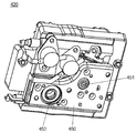
- the steam supply mechanism 300 includes at least a water supply valve 310 used as a part of the distribution unit 141 and a water storage tank 320 disposed below the storage tank 200.
- the water supply valve 310 controls water supply to the water storage tank 320. That is, when the water supply valve 310 is opened, water is supplied from the water supply port 140 to the water storage tank 320. When the water supply valve 310 is closed, the water supply to the water storage tank 320 is stopped.
- the steam supply mechanism 300 further includes a pump 330 attached to the water storage tank 320 and a steam generator 400 that receives water discharged from the pump 330.
- the pump 330 performs a water supply operation intermittently or continuously to the steam generation unit 400. At this time, during the intermittent water supply operation, the pump 330 supplies an appropriate amount of water adjusted so that instantaneous steam generation occurs to the steam generation unit 400 described later.
- impurities (scale) and the like contained in water used for generating steam can be washed away from the steam generation unit 400.
- the steam supply mechanism 300 further includes a steam conduction pipe 340 extending downward from the steam generation unit 400.
- the front portion 222 of the water tank 220 forms a watertight seal structure in cooperation with the peripheral wall portion 223 that surrounds the peripheral wall 211 of the rotating drum 210 and the packing structure 130.
- the steam conduction pipe 340 of the steam supply mechanism 300 is connected to the peripheral wall part 223 of the front part 222. Thereby, the steam generated in the steam generating unit 400 is supplied to the storage tank 200 through the steam conduction pipe 340.
- it is preferable that at least a part of the steam conduction pipe 340 has, for example, a bellows shape so that vibration generated by the rotation of the storage tank 200 is not transmitted to the steam generation unit 400.
- the pump 330 can forcibly supply water from the water storage tank 320 to the steam generator 420 (see FIG. 8) in the steam generator 400. it can. Therefore, the steam generator 420 can be disposed above the water storage tank 320.
- the water in the water storage tank 320 must be sent to the steam generator 420 by the action of gravity. Therefore, the steam generator 420 must be disposed below the water storage tank 320 without fail. That is, by arranging the pump 330, water can be forcibly supplied from the water storage tank 320 to the steam generator 420 with the pressure of the pump 330.
- the steam generator 420 is disposed above the water storage tank 320, but water can be supplied from the water storage tank 320 to the steam generator 420 by the pump 330 without any problem.
- the steam generator 420 in the case where the pump 330 is not provided, the steam generator 420 must be disposed below the water storage tank 320. Therefore, for example, when a control component such as an on-off valve that controls the supply of water from the water storage tank 320 to the steam generator 420 fails, the supply of water to the steam generator 420 cannot be controlled. Then, water is inadvertently supplied to the steam generator 420 by the action of gravity from a water storage tank 320 provided above the steam generator 420.
- the pump 330 as in the present embodiment, it is possible to avoid inadvertently supplying water from the steam generator 420 provided above the water storage tank 320.
- the steam generator 420 of the steam generation unit 400 is disposed above the storage tank 200.
- the impurities contained in the water supplied to the steam generator 420 normally cause the outer chamber wall 431, the inner chamber wall 432, the upper surface 429 of the main piece 423 constituting the steam generator 420, and It adheres to or deposits on the wall surface of the chamber space 430 formed by the lower surface 434 of the lid piece 424.
- Impurities are deposited or deposited on the wall surface forming the chamber space 430. In that case, the heat is not properly transferred between the wall surface of the chamber space 430 and the supplied water due to the impurities, so that the water supplied to the steam generator 420 is difficult to evaporate.
- the adhered or deposited impurities are discharged or dropped below the steam generator 420 by the action of pressure or gravity when water is vaporized.
- impurities are easily discharged from the chamber space 430 to the storage tank 200.
- the water storage tank 320 is disposed in the lower left space of the casing 110 when viewed from the front wall 111 of the casing 110, and the steam generator 420 is disposed in the casing 110. Place in the upper right space. That is, the steam generator 420 and the water storage tank 320 are disposed at substantially symmetrical positions (including symmetry) with respect to the central axis (rotation axis RX) of the storage tank 200.
- a detergent container (not shown) that stores detergent is disposed on one of the left and right sides in front of the upper part of the housing 110. Therefore, the space formed by the substantially cylindrical (including cylindrical) storage tank 200 and the casing 110 excluding the position occupied by the detergent storage section is effective for arranging the water storage tank 320 and the steam generator 420. It can be used for.
- the water storage tank 320 is disposed on the rear left side of the housing 110 as shown in FIG. 2.
- the steam generator 420 when the steam generator 420 is disposed in front of the upper right side of the housing 110, the steam generator 420 is formed between the inner surface of the substantially rectangular box shape (including the rectangular box shape) housing 110 and the outer peripheral surface of the storage tank 200.
- This space can be effectively utilized to arrange the water storage tank 320 and the steam generator 420.
- the design dimensions of the water storage tank 320 and the steam generator 420 can be designed to be maximally accommodated in the space allowed by the washing machine 100.
- the water storage tank 320 is disposed at a position substantially symmetrical to the detergent container with respect to the central axis (rotation axis RX) of the container tank 200, and the steam generator 420 is accommodated.
- FIG. Also in this case, the space inside the housing 110 can be effectively utilized as described above.
- the water tank 320 may be disposed below the detergent container, and the steam generator 420 may be disposed above the water tank 320.
- the steam generator 420 may be disposed at a position substantially symmetrical to the water storage tank 320 with respect to a vertical plane including the rotation axis RX of the storage tank 200.
- the water storage tank 320 and the steam generator 420 may be disposed at substantially symmetrical positions with respect to the rotation axis RX of the storage tank 200 or the horizontal plane HP including the rotation axis RX.
- the water storage tank 320 and the steam generator 420 are disposed at positions that are substantially symmetrical with respect to a vertical plane that passes through the approximate center (including the center) of the casing 110 in the front-rear direction.
- 4A and 4B are schematic perspective views of a steam generation unit of the steam supply mechanism in the same embodiment.
- 6A to 6C are schematic perspective views of the steam generator of the steam generating unit according to the embodiment.
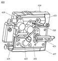
- the steam generation unit 400 includes a case 410 having a substantially rectangular box shape (including a rectangular box shape), and a steam generator 420 accommodated in the case 410.
- the case 410 includes a container part 411 having a bottom wall part 414 for accommodating the steam generator 420, and a cover part 412 including a cover part peripheral wall 416 provided with an upper wall 415 and a protruding piece 417 covering the container part 411.
- An opening 413 is formed in the bottom wall portion 414 of the container portion 411.
- the steam generator 420 is connected to the pump 330 via the connection pipe 421 and a tube (not shown), and is connected to the steam conduction pipe 340 via the exhaust pipe 422.
- connection pipe 421 and the exhaust pipe 422 of the steam generator 420 are fixed to a substantially planar (for example, plate-shaped) fixing member 450, and the fixing member 450 is fixed to the steam generator 420.
- the main piece 423 is fixed. Thereby, the connection pipe 421 and the exhaust pipe 422 are stably fixed to the steam generator 420.
- connection pipe 421 and the exhaust pipe 422 are connected (separated) from the steam generator 420 by the fixing member 450. Thereby, the heat generated by the steam generator 420 can be prevented from being conducted to the connection pipe 421 and the exhaust pipe 422. As a result, thermal deformation and thermal deterioration of the connection pipe 421 and the exhaust pipe 422 can be suppressed.
- the inlet 437 (described later) and the connection pipe 421 are the first seal member 451
- the exhaust port 438 (described later) and the exhaust pipe 422 are the second seal member 452. Hermetically sealed. This prevents leakage of steam or water.
- the fixing member 450 is preferably made of a metal such as iron or stainless steel.
- the heat conduction of iron or stainless steel constituting the fixing member 450 is lower than the heat conductivity of the steam generator 420 made of a material such as aluminum. Therefore, heat conduction from the main piece 423 (that is, the steam generator 420) to the fixing member 450 is suppressed. Thereby, the thermal deformation and thermal deterioration of the connection pipe 421 and the exhaust pipe 422 connected to the fixing member 450 can be further suppressed.
- the connection pipe 421 and the exhaust pipe 422 fixed to the fixing member 450 are disposed so as to protrude downward through an opening 413 formed in the bottom wall part 414 of the steam generation part 400.
- FIG. 5 is a schematic perspective view of an attachment structure for connecting the lid of the steam generating unit and the housing in the same embodiment.
- the housing 110 is composed of at least a right wall 115 erected between the front wall 111 and the rear wall 112, and a left wall 116 opposite to the right wall 115. Is done.
- the housing 110 further includes a first reinforcement frame 117 disposed along the upper edge of the right wall 115 and a second reinforcement frame 118 disposed along the upper edge of the front wall 111.
- the lid portion 412 constituting the steam generating unit 400 includes an upper wall 415 having a substantially rectangular shape (including a rectangular shape) and a lower side (case 410 side) from the edge of the upper wall 415. ) And a projecting piece 417 projecting forward (to the front wall 111 side of the housing 110) from the lid peripheral wall 416.
- casing 110 of the washing machine 100 and the upper wall 415 of the cover part 412 of the steam generation part 400 are connected by the 1st attachment piece 151 shown in the upper right figure of FIG.
- the second reinforcing frame 118 and the protruding piece 417 are connected by the second mounting piece 152 shown in the upper left of FIG.
- the lid portion 412 of the steam generation unit 400 and the housing top wall 113 of the housing 110 are separated from each other via the first attachment piece 151 and the second attachment piece 152 provided so as to protrude upward from the lid portion 412. Attached. As a result, it is possible to mitigate (suppress) the heat generated in the steam generation unit 400 from being transmitted to the housing 110.
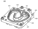
- the steam generator 420 includes a main piece 423 having a substantially rectangular shape (including a rectangular shape), a lid piece 424 disposed on the main piece 423, and a periphery of the main piece 423.
- a linear heater 425 such as a sheathed heater is provided in the main piece 423 from the surface 428.
- main piece 423 and lid piece 424 are formed of a material having higher thermal conductivity than that of fixing member 450 described above, such as aluminum. Thereby, the main piece 423 and the lid piece 424 are appropriately and efficiently heated by the heater 425.
- a thermistor 426 is further attached to the main piece lower surface 427 of the main piece 423 of the steam generator 420.
- the above-described connection pipe 421 and exhaust pipe 422 fixed to the fixing member 450 are also attached to the main piece lower surface 427 of the main piece 423 constituting the steam generator 420.
- the heater 425 is controlled by temperature information obtained by the thermistor 426. Thereby, the temperature of the main piece 423 and the lid piece 424 is kept substantially constant (including constant). Instead of the thermistor 426, a thermostat that controls on / off of power to the heater 425 at a predetermined temperature may be used, and the same effect can be obtained.
- FIG. 7 is a schematic perspective view of the main piece of the steam generator in the same embodiment.
- the main piece 423 has a main piece lower surface 427, a peripheral surface 428, and an upper surface 429.
- a connecting pipe 421 and an exhaust pipe 422 are attached to the main piece lower surface 427 via a thermistor 426 and a fixing member 450.
- a heater 425 is disposed on the peripheral surface 428.
- the main piece 423 is erected from the upper surface 429 toward the lid piece 424 constituting one of the steam generators 420 to form, for example, a substantially triangular (including triangular) chamber space 430.
- the chamber space 430 is defined and formed by an outer chamber wall 431 and an inner chamber wall 432 having, for example, a substantially J shape (including a J shape) that defines a flow path of steam in the chamber space 430. .
- FIG. 8 is a schematic exploded perspective view of the steam generator in the same embodiment.
- FIG. 9 is a schematic perspective view of a lid piece of the steam generator in the same embodiment.
- the steam generator 420 includes a packing ring 433 made of, for example, heat resistant rubber and attached to the main piece 423 so as to surround the outer periphery of the outer chamber wall 431.
- the lid piece 424 includes a lower surface 434 facing the main piece 423, and a shield wall 435 having substantially the same shape (including the same shape) as the outer chamber wall 431 of the main piece 423.
- the shield wall 435 of the lid piece 424 compresses the packing ring 433.
- the chamber space 430 of the steam generator 420 is kept airtight.
- the main piece 423 is formed with an inlet 437 for allowing water supplied through a connecting pipe 421 connected to the main piece lower surface 427 via the fixing member 450 to flow into the chamber space 430.
- the inflow port 437 is formed substantially at the center (including the center) of the chamber space 430, and its periphery is surrounded by the inner chamber wall 432.
- the steam generator 420 of the present embodiment is configured.
- the water is emitted upward (on the lid piece 424 side) through the connection pipe 421 and the inflow port 437. Then, the water emitted to the chamber space 430 of the steam generator 420 passes through the inner chamber wall 432, the upper surface 429 of the main piece 423 surrounded by the inner chamber wall 432 and / or the lid piece 424 located above the inflow port 437. Collide with the lower surface 434. At this time, the steam generator 420 is heated by the heater 425 (for example, about 200 ° C.) and has high thermal energy.
- the heater 425 for example, about 200 ° C.
- a water supply operation is intermittently performed by the pump 330 of the steam supply mechanism 300 to supply an appropriate amount of water into the chamber space 430 of the steam generator 420 (for example, about 2 cc / time).
- the pump 330 of the steam supply mechanism 300 to supply an appropriate amount of water into the chamber space 430 of the steam generator 420 (for example, about 2 cc / time).
- the internal pressure of the chamber space 430 rises abruptly as the water evaporates instantaneously.
- impurities contained in the water supplied to the steam generator 420 adhere or deposit on the wall surface forming the chamber space 430 during vaporization.
- the adhered or deposited impurities are affected by pressure due to a sudden increase in internal pressure of the chamber space 430 during vaporization. As a result, the impurities are easily discharged out of the chamber space 430.
- FIG. 10 is a schematic plan view of the main piece of the steam generator in the same embodiment.
- the heater 425 is disposed so as to extend along a substantially U-shaped (including U-shaped) path in the main piece 423. Thereby, the heater 425 surrounds the inflow port 437 to which the connection pipe 421 is attached. Therefore, the inner chamber wall 432 and the region surrounded by the inner chamber wall 432 become the highest temperature in the chamber space 430 due to the heating of the heater 425. As a result, the water emitted into the chamber space 430 through the inflow port 437 is instantly evaporated.
- the inner chamber wall 432 extends in a substantially J shape within the chamber space 430 defined by the outer chamber wall 431. That is, the inner chamber wall 432 forms a spiral flow path in the chamber space 430.
- an exhaust port 438 is formed in the main piece 423 near the end of the flow path through which water and steam flow. Therefore, the vapor generated in the space surrounded by the inner chamber wall 432 moves toward the exhaust port 438 as the internal pressure of the chamber space 430 increases. Then, the steam that has reached the exhaust port 438 is exhausted downward in the vertical direction through the exhaust pipe 422 attached to the exhaust port 438.
- the heater 425 is provided so as to extend in a substantially U shape (including a U shape) along the outer path of the spiral flow path. Therefore, the steam generated in the space surrounded by the inner chamber wall 432 moves toward the exhaust pipe 422 while being heated. Thereby, high-temperature steam is exhausted from the exhaust pipe 422 of the steam generator 420.
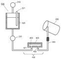
- FIG. 11 is a schematic view of a water supply mechanism of the steam supply mechanism in the same embodiment.
- the water supply mechanism 500 that emits water to the chamber space 430 of the steam generator 420 has the above-described water supply valve 310, water storage tank 320, pump 330, connection pipe 421, and water level in the water storage tank 320.
- a water level sensor 321 for measuring is provided.
- the water supply valve 310 supplies water to the water storage tank 320 or stops water supply to the water storage tank 320 according to the water level detected by the water level sensor 321.
- the water supply valve 310 may be controlled according to the operation time and / or operation pattern of the pump 330 (intermittent water supply operation and / or continuous water supply operation). For example, the amount of water supplied from the water supply valve 310 may be adjusted so that the water storage tank 320 becomes empty when the operation of the pump 330 ends. Thereby, even if outside temperature falls, freezing of the water in the water storage tank 320 becomes difficult to occur. As a result, the reliability of the washing machine 100 can be further improved.
- the pump 330 supplies the water stored in the water storage tank 320 to the chamber space 430 of the steam generator 420 through the connection pipe 421. At this time, in the intermittent water supply operation by the pump 330, for example, the supply amount, the supply time, the supply interval, and the like are adjusted so that the water emitted into the chamber space 430 evaporates instantaneously.
- the exhaust pipe 422 of the steam generator 420 is connected to the steam conduction pipe 340. Accordingly, the steam generated in the chamber space 430 by the intermittent water supply operation of the pump 330 and the water flowing into the chamber space 430 by the continuous water supply operation of the pump 330 are passed through the exhaust pipe 422 and the steam conduction pipe 340. Can flow into the storage tank 200.
- the water supply mechanism of the steam supply mechanism of the washing machine 100 of the present embodiment is configured.
- FIG. 12 is a schematic rear view of the front part of the storage tub of the washing machine in the same embodiment.
- the annular portion 224 of the front portion 222 of the water tank 220 has an inner surface 225 that faces the rotating drum 210 and an outer surface 226 that faces the front wall 111 of the housing 110.
- FIG. 12 mainly shows the inner surface 225 of the annular portion 224 of the front portion 222 of the water tank 220.
- the steam supply mechanism 300 described above connects the branch pipe 351 attached to the inner surface 225, the nozzle 352 disposed above the branch pipe 351, and the branch pipe 351 and the nozzle 352.
- a steam tube 353 is further provided.
- the steam conduction pipe 340 is connected to the branch pipe 351 through the peripheral wall portion 223 of the water tank 220.
- the steam reaching the branch pipe 351 Since the steam reaching the branch pipe 351 has a high temperature, it is guided to the steam tube 353 and flows to the nozzle 352 disposed above the branch pipe 351. Finally, the steam is jetted from the nozzle 352 into the rotating drum 210 of the storage tank 200.
- the exhaust pipe 422, the steam conducting pipe 340, the branch pipe 351, and the steam tube 353 guide the steam generated in the chamber space 430 to the nozzle 352.
- the pump 330 that performs the intermittent water supply operation emits an appropriate amount of water to the high-temperature chamber space 430 heated by the heater 425, whereby water is instantly evaporated.
- the internal pressure of the chamber space 430 of the steam generator 420 rapidly increases due to water evaporation.
- the generated steam is injected from the nozzle 352 at a high pressure.
- the steam is injected so as to cross the internal space of the storage tank 200 up and down.
- a branch pipe 351 for guiding steam from the steam conduction pipe 340 to the steam tube 353 includes a parent pipe 354 connected to the steam conduction pipe 340, an upper pipe 355 bent upward from the parent pipe 354, and a parent pipe 354.
- the upper tube 355 is connected to the steam tube 353, and defines an upward path for the steam toward the nozzle 352.
- the lower tube 356 defines a downward path. Specifically, when continuous water supply operation is performed by the pump 330, water mainly flows into the branch pipe 351 through the steam conduction pipe 340. Then, the water that has flowed into the branch pipe 351 flows down through the lower pipe 356 by gravity.
- the parent tube 354 and the upper tube 355 of the branch tube 351 are connected at an obtuse angle ⁇ 1 and the parent tube 354 and the lower tube 356 are an acute angle. They are connected at an angle ⁇ 2.
- the included angle ⁇ 2 is an acute angle
- the flow loss from the parent tube 354 to the lower tube 356 becomes relatively large. Therefore, the steam that has flowed into the parent pipe 354 hardly flows to the lower child pipe 356 and flows mainly to the upper child pipe 355.
- the upper pipe 355 defines an upward flow path, the water flowing into the parent pipe 354 hardly flows into the upper pipe 355 and mainly flows into the lower pipe 356 due to the action of gravity. As a result, the flow path of steam and the flow path of water can be appropriately separated by the branch pipe 351.
- FIG. 13 is an explanatory view schematically showing the relationship between the intermittent operation of the pump of the water supply mechanism and the temperature in the chamber space in the same embodiment.
- the period during which the pump 330 is operating is set shorter than the period during which the pump 330 is stopped (OFF period). Accordingly, an appropriate amount of water can be emitted into the chamber space 430 of the steam generator 420 of the steam generation unit 400.
- the intervals between the ON period and the OFF period shown in FIG. 13 are relative, and needless to say, the interval is changed depending on the volume of the chamber space 430, the heating amount of the heater, and the necessary amount of steam.
- the pump 330 supplies a predetermined amount of water to the chamber space 430 during the ON period.
- the supplied water evaporates and becomes steam.
- the temperature of the chamber space 430 temporarily decreases due to the heat of vaporization caused by the phase change from water to steam.
- the heater 425 can sufficiently raise the temperature of the chamber space 430 during the OFF period by setting the OFF period to be relatively long. As a result, it is possible to continue supplying high-pressure steam to the storage tank 200 while the pump 330 performs an intermittent operation.
- the chamber space 430 is sufficiently heated during the OFF period.
- an appropriate amount of water that instantaneously evaporates is supplied to the thermal energy of the steam generator 420 including the chamber space 430 (for example, about 2 cc / time). Thereby, it is possible to continue to supply the high-pressure steam to the storage tank 200 satisfactorily.
- FIG. 14 will be described below with reference to FIGS. 1, 8, and 11 with respect to the effect of the steam supplied to the storage tank via the steam supply mechanism of the embodiment of the present invention, particularly the effect in the washing step. It explains using.
- FIG. 14 is an explanatory diagram schematically showing a change in the temperature of the water supplied to the water tank of the washing machine in the embodiment.
- a hot water heater 160 for heating water supplied into the water tank 220 is disposed at the bottom of the water tank 220.
- the water in the water tank 220 is heated using the hot water heater 160.
- the hot water heater 160 since the hot water heater 160 generates a large amount of heat, the temperature of the water contained in the clothes in the water tank 220 rises rapidly. And when the predetermined temperature is reached, heating of water in the water tank 220 is stopped.
- the dotted line after the heating stop shown in FIG. 14 represents a change in the temperature of water contained in the clothing when the heating by the hot water heater 160 is stopped and no steam is supplied.
- the solid line after stopping the heating represents a change in the temperature of the water contained in the clothing when the heating by the hot water heater 160 is stopped and the steam is supplied to the storage tank 200.
- the washing step high-temperature steam is directly supplied to the storage tub 200 toward the clothes. Therefore, the temperature drop of the water contained in the clothes in the water tank 220 is relieved (suppressed) by the high-temperature steam.
- the heater 425 used for the steam generator 420 consumes less power than the hot water heater 160 attached to the water tank 220. As a result, compared with the case where the water in the water tank 220 is kept warm using the hot water heater 160, the heat keeping by supplying the high-temperature steam can be realized with less power consumption. Therefore, in the washing step, after stopping the hot water heater 160 using the pump 330, it is preferable to perform intermittent water supply operation to supply high temperature steam to the storage tank.
- the rotating drum 210 is rotated at a high speed by the motor 231. At this time, as shown in FIG. 1, a large number of small holes 219 are formed in the peripheral wall 211 of the rotary drum 210.
- the clothing housed in the rotating drum 210 is pressed against the peripheral wall 211 by centrifugal force, and the moisture contained in the clothing is discharged out of the rotating drum 210 through the small holes 219. As a result, the clothing is properly dehydrated.
- the fibers of the dehydrated clothing are likely to be hydrogen-bonded to each other, and the hydrogen bonding between the fibers becomes a factor that causes wrinkles of the clothing.
- the power supply to the heater 425 is stopped to cool the steam generator 420.
- a continuous water supply operation is started by the pump 330. Accordingly, water continuously flows from the water storage tank 320 into the chamber space 430 of the steam generator 420. The water that has flowed into the chamber space 430 takes heat from the steam generator 420 and then flows from the steam conduction pipe 340 into the storage tank 200 through the branch pipe 351. As a result, the steam generator 420 can be cooled in a short period of time.
- FIG. 15 the control of the door body according to the embodiment of the present invention will be described using FIG. 15 with reference to FIGS. 1 and 6B. This is to control the user not to open the door 120 inadvertently when high-temperature steam is present in the storage tank 200.
- FIG. 15 is a block diagram schematically showing control on the door body based on the temperature of the steam generator in the embodiment.
- the washing machine 100 includes a lock mechanism 121 that locks the door body 120 in the closed position, and a control unit 122 that controls locking and unlocking of the lock mechanism 121.
- a lock mechanism 121 that locks the door body 120 in the closed position
- a control unit 122 that controls locking and unlocking of the lock mechanism 121.
- the mechanical and electrical mechanisms of the lock mechanism 121 may use a known washing machine structure.
- the steam generator 420 includes a thermistor 426.
- the thermistor 426 detects the temperature of the main piece 423 of the steam generator 420 and outputs a signal corresponding to the detected temperature to the control unit 122.
- the controller 122 keeps the door 120 locked by the lock mechanism 121 until the signal output from the thermistor 426 reaches a temperature equal to or lower than a predetermined value. Thereby, the internal space of the storage tank 200 is isolated from the outside until the steam generator 420 becomes a predetermined temperature or lower. As a result, the user can be prevented from coming into contact with high-temperature steam, and the washing machine 100 that is safe and highly reliable can be realized.
- the present invention is suitably used for an apparatus for processing clothing using steam.
Abstract
衣類を収容する収容槽と、収容槽へ蒸気を噴射する蒸気供給機構とを備える。蒸気供給機構は、チャンバを規定する壁面を有する蒸気発生器(420)と、壁面を加熱するヒータ(425)と、壁面に水を出射する給水機構とを有する。蒸気発生器(420)は、給水機構からの水が流入する流入口と、壁面で気化した蒸気が流出する排気口とを備え、流入口と接続管(421)、および排気口と排気管(422)とは、固定部材(450)を介して、蒸気発生器(420)から離れて接続される。これにより、衣類に蒸気を効率的に供給するとともに、接続管(421)および排気管(422)を、蒸気発生器(420)に固定して、熱変形や熱劣化を抑制できる。
Description
本発明は、衣類を洗濯、脱水および/または乾燥する衣類処理装置に関する。
近年、衣類に蒸気を供給し、殺菌を行う洗濯機が開発されている(例えば、特許文献1参照)。
特許文献1に記載の洗濯機は、水中に浸されたヒータを用いて、蒸気を発生させ、衣類が収容されたドラムに蒸気を供給する構成を有する。
しかしながら、ヒータにより直接、水を蒸発させるため、ドラムへ供給する蒸気の圧力が低い。そのため、ドラム内の空間を蒸気で満たすには、時間がかかる。一方、時間を短縮するために、蒸気を多量に発生させると、多量の電力が必要となるという課題がある。
上記課題を解決するために、本発明の衣類処理装置は、衣類を収容する収容槽と、収容槽へ蒸気を供給する蒸気供給機構と、を備える。蒸気供給機構は、蒸気を発生させるためのチャンバを規定する壁面を有する蒸気発生器と、壁面を加熱するヒータと、壁面に水を出射する給水機構と、を有する。そして、蒸気発生器は、給水機構からの水が接続管を介して流入する流入口と、壁面で気化した蒸気が排気管を介して流出する排気口とを備え、流入口と接続管、および排気口と排気管とは、固定部材を介して接続される構成を有する。
上記構成によれば、蒸気発生器は、蒸気を発生させるためのチャンバを規定する壁面を有する。給水機構は、ヒータによって加熱された壁面に水を出射する。出射された水は、ヒータによって加熱された壁面に当たって水蒸気となる。そして、水が水蒸気となるときの気化圧によって、蒸気発生器のチャンバ内の圧力が急激に増大し、衣類が収容された収容槽へ蒸気が噴射される。
これにより、蒸気を漏出させて、衣類を蒸気雰囲気下におく従来技術とは異なり、高い圧力の蒸気を噴射して衣類に直接的に蒸気を供給する。その結果、高い供給効率で蒸気を衣類に供給できる衣類処理装置を実現できる。
また、流入口と接続管、および排気口と排気管とが、固定部材を介して接続される。そのため、蒸気発生器で生じる熱が、接続管や排気管に直接伝わらない。その結果、接続管や排気管の熱変形や熱劣化を抑制して、信頼性を向上できる。
以下、本発明の実施の形態の衣類処理装置について、図面を参照しながら説明する。なお、この実施の形態によって本発明が限定されるものではない。また、以下では、衣類処理装置として、洗濯機を例に説明する。さらに、以下の説明で用いられる「上」、「下」、「左」や「右」などの方向を表す用語は、単に、説明の明瞭化を目的とし、衣類処理装置の原理を何ら限定するものではない。また、衣類処理装置の原理は、衣類を洗濯および乾燥する能力を有する装置や衣類を乾燥する装置にも適用可能である。
(実施の形態)
<洗濯機の構成>
以下に、本発明の実施の形態の洗濯機の構成について、図1を用いて説明する。
<洗濯機の構成>
以下に、本発明の実施の形態の洗濯機の構成について、図1を用いて説明する。
図1は、本発明の実施の形態における衣類処理装置として例示される洗濯機の概略的な縦断面図である。
図1に示すように、本実施の形態の洗濯機100は、少なくとも筐体110と、筐体110内で衣類を収容する収容槽200と、を備える。収容槽200は、回転軸RXを取り囲む略円筒形状(円筒形状を含む)の周壁211を有する回転ドラム210と、回転ドラム210を収容する水槽220と、を含む。
また、筐体110は、収容槽200へ衣類を投入するための投入口が形成された前壁111と、前壁111とは反対側の後壁112と、略水平(水平を含む)に延びる筐体天壁113と、筐体天壁113と反対側の筐体底壁114と、後述する左壁および右壁などから構成される。このとき、収容槽200の回転ドラム210および水槽220は、前壁111に向けて開口する。
また、洗濯機100は、筐体110の前壁111に取り付けられた扉体120をさらに備える。扉体120は、前壁111に形成された投入口を閉塞する閉位置と投入口を開放する開位置との間で回動する。これにより、使用者は、扉体120を開位置に回動させ、前壁111の投入口を通じて、衣類を収容槽200へ投入できる。その後、使用者は、扉体120を閉位置に移動させ、洗濯機100に投入した衣類を洗濯できる。なお、図1は、扉体120が、閉位置の状態を示している。
また、回転ドラム210は、周壁211と底壁212とを備え、筐体110の前壁111と後壁112との間で延びる回転軸RX周りに回転する。このとき、収容槽200に投入された衣類は、回転ドラム210の回転に伴って回転ドラム210内を移動する。これにより、衣類は、洗い、すすぎおよび/または脱水などの様々な処理を受ける。なお、回転ドラム210の底壁212は、閉位置にある扉体120に対向して設けられる。
また、水槽220は、少なくとも底部221と、前部222とから構成される。底部221は、回転ドラム210の底壁212および周壁211の一部を取り囲む。前部222は、水槽220の底部221と扉体120との間に配置され、対向する回転ドラム210の周壁211の残りの部分を取り囲む。
また、収容槽200は、回転ドラム210の底壁212に取り付けられ、回転軸RXに沿って筐体110の後壁112に向けて延びる回転シャフト230を有する。そのため、回転シャフト230は、水槽220の底部221を貫通し、水槽220と後壁112との間に突出するように設けられる。
さらに、洗濯機100は、水槽220の下方に据え付けられたモータ231と、水槽220の外に露出した回転シャフト230に取り付けられたプーリ232と、モータ231の動力をプーリ232に伝達するベルト233と、を備える。そして、モータ231が作動すると、モータ231の動力は、ベルト233、プーリ232および回転シャフト230に伝達される。その結果、回転ドラム210は、水槽220内で回転する。
また、洗濯機100は、水槽220の前部222と扉体120との間に配設されたパッキン構造130をさらに備える。そして、扉体120が閉位置に回動されると、扉体120によりパッキン構造130が圧縮される。その結果、圧縮されたパッキン構造130により、扉体120と前部222との間に水密シール構造が形成される。
また、洗濯機100は、蛇口(図示せず)に接続される給水口140と、給水口140を介して導入された水を分配するための分配部141と、を備える。給水口140は筐体天壁113上に突出するように設けられ、分配部141は筐体天壁113と収容槽200との間に設けられる。
また、図1に示すように、洗濯機100は、洗剤が収容される洗剤収容部(図示せず)および収容槽200へ蒸気を噴射する蒸気供給機構300(後述される)を備える。このとき、分配部141は、収容槽200、洗剤収容部および蒸気供給機構300に、給水経路(図示せず)を介して選択的に水を供給するための複数の給水弁を備える。なお収容槽200および洗剤収容部への給水に対して、既知の洗濯機に用いられている技術を適用できることはいうまでもない。
<蒸気供給機構の構成>
以下に、本発明の実施の形態の洗濯機の蒸発供給機構の構成について、図1を参照しながら、図2と図3を用いて説明する。
以下に、本発明の実施の形態の洗濯機の蒸発供給機構の構成について、図1を参照しながら、図2と図3を用いて説明する。
図2は、同実施の形態における洗濯機の概略的な透視斜視図である。図3は、同実施の形態における洗濯機の筐体に収容された蒸気供給機構の概略的な斜視図である。
なお、図2と図3には筐体110を点線で表し、図3には収容槽200を示していない。また、図3中の矢印は、各部を接続する給水経路を概略的に表している。
図2と図3に示すように、蒸気供給機構300は、少なくとも分配部141の一部として用いられる給水弁310と、収容槽200の下方に配置された貯水槽320と、を備える。給水弁310は、貯水槽320への給水を制御する。つまり、給水弁310を開くと、給水口140から貯水槽320へ水を供給する。給水弁310を閉じると、貯水槽320への給水が停止する。
また、蒸気供給機構300は、貯水槽320に取り付けられたポンプ330と、ポンプ330から吐出された水を受ける蒸気発生部400と、をさらに備える。ポンプ330は、蒸気発生部400に間欠式にあるいは連続的に給水動作を行う。このとき、間欠式の給水動作の間、ポンプ330は、瞬間的な蒸気発生が生ずるように調整された適量の水を、後述する蒸気発生部400に供給する。一方、ポンプ330で蒸気発生部400に連続的に給水を行う場合、蒸気発生のために用いられた水に含まれる不純物(スケール)などを蒸気発生部400から洗い流すことができる。
また、図2に示すように、蒸気供給機構300は、蒸気発生部400から下方に延びる蒸気導通管340をさらに備える。このとき、図1を用いて上述したように、水槽220の前部222は、回転ドラム210の周壁211を取り囲む周壁部223と、パッキン構造130と協働して水密シール構造を形成する図2に示す環状部224と、を備えている。そして、蒸気供給機構300の蒸気導通管340は、前部222の周壁部223へ接続されている。これにより、蒸気発生部400で発生した蒸気は、蒸気導通管340を通じて、収容槽200へ供給される。なお、蒸気導通管340は、収容槽200の回転により発生する振動が蒸気発生部400に伝達しないように、少なくとも一部を、例えば蛇腹形状とするのが好ましい。
上述したように、本実施の形態の蒸気供給機構300によれば、ポンプ330により、貯水槽320から蒸気発生部400内の蒸気発生器420(図8参照)に強制的に給水を行うことができる。そのため、蒸気発生器420を貯水槽320より上方に配置できる。一方、ポンプ330を設けずに、貯水槽320から蒸気発生器420に給水を行う場合、貯水槽320の水を重力の作用で蒸気発生器420に送らなければならない。そのため、蒸気発生器420を貯水槽320より必ず下位に配置しなければならない。つまり、ポンプ330を配置することによって、水をポンプ330の圧力で強制的に貯水槽320から蒸気発生器420へ供給できる。これにより、蒸気発生器420と貯水槽320との配置に伴う相互の上下関係などの制約を解消できる。その結果、貯水槽320と蒸気発生器420との配置の自由度が増すため、筐体110内のスペースを有効に活用できる。
また、図2に示すように、蒸気発生器420は、貯水槽320よりも上方に配置されるが、ポンプ330により貯水槽320から蒸気発生器420へ水を問題なく供給できる。
なお、不慮の故障などの要因により、蒸気発生器420に水が不用意に流れ込むと、必要外の蒸気が発生する。しかしながら、本実施の形態のように、ポンプ330を配設することにより、貯水槽320を、蒸気発生器420より下方に配置することが可能となる。そのため、もし、ポンプ330が故障などの不具合で停止し、蒸気発生器420への水の供給が制御できない場合でも、貯水槽320およびポンプ330と蒸気発生器420とを連通するホース内に滞留する水が、蒸気発生器420に不用意に流れ込むことがない。その結果、必要外の蒸気の発生を未然に防止できる。
一方、ポンプ330を設けない構成の場合、蒸気発生器420は貯水槽320より必ず下位に配置しなければならない。そのため、例えば貯水槽320から蒸気発生器420へ水の供給を制御する開閉弁などの制御部品が故障した場合、蒸気発生器420への水の供給が制御できなくなる。そして、蒸気発生器420の上方に設けた貯水槽320から水が、重力の作用により蒸気発生器420へ不用意に供給されることになる。しかし、本実施の形態のように、ポンプ330を設けることにより、貯水槽320より上方に設けた蒸気発生器420から不用意に水が供給されることを未然に回避できる。
さらに、本実施の形態では、図2に示すように、蒸気発生部400の蒸気発生器420は、収容槽200よりも上方に配置される。このとき、通常、蒸気発生器420に供給する水に含有される不純物が、水の気化時に、蒸気発生器420を構成する主片423の外チャンバ壁431、内チャンバ壁432、上面429、および蓋片424の下面434により形成されるチャンバ空間430の壁面に付着あるいは析出する。そして、不純物がチャンバ空間430を形成する壁面に付着あるいは析出して、堆積する。その場合、不純物により、チャンバ空間430の壁面と供給された水との間で熱伝達が適切に行われなくなるため、蒸気発生器420に供給される水が蒸発しにくくなる。
しかしながら、蒸気発生器420を収容槽200よりも上方に配置することにより、付着あるいは析出した不純物は、水の気化時の圧力や重力の作用で、蒸気発生器420の下方へ排出あるいは落下する。これにより、不純物は、チャンバ空間430内から収容槽200へ容易に排出される。その結果、蒸気発生器420のチャンバ空間430の壁面に付着あるいは析出した不純物の堆積を防止できる。さらに、不純物の堆積による、水を気化する能力の低下を未然に防止できる。
また、本実施の形態では、図2に示すように、筐体110の前壁111から見て、貯水槽320は筐体110の左下の空間に配置し、蒸気発生器420は筐体110の右上の空間に配置する。つまり、蒸気発生器420および貯水槽320は、収容槽200の中心軸(回転軸RX)に対して、略対称(対称を含む)の位置に配置される。
なお、一般的な洗濯機の場合、洗剤を収容する洗剤収容部(図示せず)は、筐体110の上部前方の左側および右側のうちの一方に配設される。そこで、洗剤収容部が占める位置を除いた略円筒形状(円筒形状を含む)の収容槽200と筐体110とにより形成される空間を、貯水槽320と蒸気発生器420を配置するために有効に活用することができる。例えば、洗剤収容部が筐体110の上部前方の左側に配置される場合、図2に示すように、貯水槽320は、筐体110の左側下方の後方に配置する。このとき、蒸気発生器420が筐体110の右側上方の前方に配置すると、略矩形箱状(矩形箱状を含む)の筐体110の内面ならびに収容槽200の外周面との間で形成される空間を、貯水槽320と蒸気発生器420を配置するために有効に活用できる。その結果、貯水槽320および蒸気発生器420の設計寸法を、洗濯機100で許容された空間内に最大限に収容できる大きさに設計することができる。
また、洗剤収容部が前述の位置にある場合に、貯水槽320を収容槽200の中心軸(回転軸RX)に対して洗剤収容部と略対称の位置に配置し、蒸気発生器420を収容槽200の回転軸RXを含む水平面HPに対して、貯水槽320と略対称な位置に配置してもよい。この場合も、前述と同様に筐体110の内部の空間を有効に活用することができる。
さらに、洗剤収容部が前述の位置にある場合に、貯水槽320を洗剤収容部の下方に配置し、蒸気発生器420を貯水槽320より上方に配置してもよい。このとき、蒸気発生器420は、収容槽200の回転軸RXを含む鉛直面に対して、貯水槽320と略対称な位置に配置してもよい。その結果、前述と同様に筐体110の内部の空間を有効に活用することができる。
また、収容槽200の回転軸RXが、筐体110の前後方向に傾斜している場合(例えば、回転ドラム210の回転軸RXが、後壁112から前壁111に向けて上方に傾斜しているような場合)、貯水槽320および蒸気発生器420は、収容槽200の回転軸RXあるいは回転軸RXを含む水平面HPに対して、略対称な位置に配置してもよい。例えば、貯水槽320および蒸気発生器420を筐体110の前後方向の略中心(中心を含む)を通る鉛直面に対し略対称な位置に配置する。これにより、筐体110の内面と収容槽200の外周面との間で形成される内部空間を、貯水槽320と蒸気発生器420とを配置するために有効に活用することができる。
つぎに、蒸気供給機構300の蒸気発生部400の構成について、図3を参照しながら、図4Aと図4Bおよび図6Aから図6Cを用いて説明する。
図4Aと図4Bは、同実施の形態における蒸気供給機構の蒸気発生部の概略的な斜視図である。図6Aから図6Cは、同実施の形態における蒸気発生部の蒸気発生器の概略的な斜視図である。
図4Aと図4Bに示すように、蒸気発生部400は、略矩形箱状(矩形箱状を含む)のケース410と、ケース410内に収容された蒸気発生器420と、を有する。ケース410は、蒸気発生器420を収容する底壁部414を有する容器部411と、容器部411を覆う上壁415および突出片417が設けられた蓋部周壁416からなる蓋部412と、を備える。容器部411の底壁部414には、開口部413が形成されている。
このとき、蒸気発生器420は、接続管421およびチューブ(図示せず)を介してポンプ330に接続され、排気管422を介して蒸気導通管340に接続される。
また、図6Aから図6Cに示すように、蒸気発生器420の接続管421および排気管422は、略平面状(例えば板状)の固定部材450に固定され、固定部材450は蒸気発生器420の主片423に固定される。これにより、接続管421および排気管422が、蒸気発生器420に安定して固定される。
また、接続管421および排気管422は、固定部材450により、蒸気発生器420から離れて(離間して)接続される。これにより、蒸気発生器420で発生した熱が、接続管421および排気管422へ伝導することを抑制できる。その結果、接続管421および排気管422の熱変形や熱劣化を抑制できる。
このとき、図6Cに示すように、流入口437(後述する)と接続管421は、第1シール部材451で、排気口438(後述する)と排気管422は、第2シール部材452によって、気密的にシールされる。これにより、蒸気や水などの漏れを防止する。
なお、固定部材450は、例えば鉄やステンレス鋼などの金属から構成されることが好ましい。この場合、固定部材450を構成する鉄やステンレス鋼の熱伝導は、例えばアルミニウムなどの材料で構成される蒸気発生器420の熱伝導率より低い。そのため、主片423(すなわち蒸気発生器420)から固定部材450への熱伝導が抑制される。これにより、固定部材450に接続される接続管421および排気管422の熱変形や熱劣化をさらに抑制できる。なお、固定部材450に固定された接続管421および排気管422は、蒸気発生部400の底壁部414に形成された開口部413を通じて下方に突出するように配置される。
つぎに、蒸気供給機構300の蒸気発生部400を洗濯機100の筐体110に取り付ける取付構造について、図3と図4Aを参照しながら、図5を用いて説明する。
図5は、同実施の形態における蒸気発生部の蓋部と筐体とを接続するための取付構造の概略的な斜視図である。
まず、図3に示すように、筐体110は、少なくとも前壁111と後壁112との間で立設された右壁115と、右壁115とは反対側の左壁116と、から構成される。さらに、筐体110は、右壁115の上縁に沿って配設された第1補強フレーム117と、前壁111の上縁に沿って配設された第2補強フレーム118と、を備える。
また、図5の下図に示すように、蒸気発生部400を構成する蓋部412は、略矩形状(矩形状を含む)の上壁415と、上壁415の縁部から下方(ケース410側)に突出する蓋部周壁416と、蓋部周壁416から前方(筐体110の前壁111側)に突出する突出片417と、を有する。
そして、図5の上図右に示す第1取付片151により洗濯機100の筐体110に設けられた第1補強フレーム117と蒸気発生部400の蓋部412の上壁415とを接続する。一方、図5の上図左に示す第2取付片152により第2補強フレーム118と突出片417とを接続する。
つまり、蒸気発生部400の蓋部412と筐体110の筐体天壁113が、蓋部412から上方に突出して設けられた第1取付片151および第2取付片152を介して、離間して取り付けられる。その結果、蒸気発生部400で発生した熱が、筐体110へ伝達することを緩和(抑制)できる。
つぎに、蒸気発生部400の蒸気発生器420の構成について、図6Aから図6Cを用いて、詳細に説明する。
図6Aから図6Cに示すように、蒸気発生器420は、略矩形状(矩形状を含む)の主片423と、主片423上に配設される蓋片424と、主片423の周面428から主片423内に配設される、例えばシーズヒータなどの線状のヒータ425とから構成される。なお、本実施の形態では、主片423および蓋片424は、例えばアルミニウムなどの、上述した固定部材450よりも高い熱伝導率を有する材料から形成される。これにより、主片423および蓋片424は、ヒータ425によって適切に効率よく加熱される。
また、図6Bに示すように、蒸気発生器420の主片423の主片下面427には、サーミスタ426がさらに取り付けられている。同様に、固定部材450に固定された、上述の接続管421および排気管422も、蒸気発生器420を構成する主片423の主片下面427に取り付けられている。
そして、ヒータ425は、サーミスタ426によって得られる温度情報により制御される。これにより、主片423および蓋片424の温度は、略一定(一定を含む)に保たれる。なお、サーミスタ426の代わりに、所定の温度でヒータ425への電力の入・切を制御するサーモスタットを用いてもよく、同様の効果が得られる。
つぎに、蒸気発生器420を構成する主片423の構成について、図6Bと図7を用いて、説明する。
図7は、同実施の形態における蒸気発生器の主片の概略的な斜視図である。
図6Bと図7に示すように、主片423は、主片下面427と、周面428と、上面429とを有している。主片下面427には、サーミスタ426と、固定部材450を介して接続管421および排気管422が取り付けられる。周面428には、ヒータ425が配設される。
また、主片423は、上面429から、蒸気発生器420の一方を構成する蓋片424に向けて立設して、例えば略三角形状(三角形状を含む)のチャンバ空間430が形成されている。チャンバ空間430は、外チャンバ壁431と、チャンバ空間430内で蒸気の流動経路を規定する、例えば略J字形状(J字形状を含む)の内チャンバ壁432と、により規定されて形成される。
つぎに、蒸気発生器420の構成および動作について、図3、図6Bから図7を参照しながら、図8と図9を用いて、説明する。
図8は、同実施の形態における蒸気発生器の概略的な展開斜視図である。図9は、同実施の形態における蒸気発生器の蓋片の概略的な斜視図である。
図8に示すように、蒸気発生器420は、外チャンバ壁431の外周を取り巻くように主片423に取り付けられる、例えば耐熱性ゴムなどからなるパッキンリング433を備える。
また、図8と図9に示すように、蓋片424は、主片423に対向する下面434と、主片423の外チャンバ壁431と略同形状(同形状を含む)のシールド壁435と、を有する。
そして、蓋片424を主片423に押しつけることにより、蓋片424のシールド壁435がパッキンリング433を圧縮する。その結果、蒸気発生器420のチャンバ空間430が気密に保たれる。
また、主片423は、主片下面427に固定部材450を介して接続された接続管421を通じて供給された水をチャンバ空間430内に流入するための流入口437が形成される。流入口437は、チャンバ空間430の略中央(中央を含む)に形成され、その周囲が内チャンバ壁432に取り囲まれる。
以上のように、本実施の形態の蒸気発生器420が構成される。
つぎに、蒸気発生器420の動作について、詳細に説明する。
まず、ポンプ330により貯水槽320から所定量の水が蒸気発生器420に供給されると、接続管421および流入口437を通じて、水が上向き(蓋片424側)に出射される。そして、蒸気発生器420のチャンバ空間430に出射された水は、内チャンバ壁432、内チャンバ壁432によって囲まれた主片423の上面429および/または流入口437の上方に位置する蓋片424の下面434に衝突する。このとき、蒸気発生器420は、ヒータ425によって加熱され(例えば、約200℃)、高い熱エネルギを有する。
そして、蒸気供給機構300のポンプ330により、間欠式に給水動作をして、適量の水を蒸気発生器420のチャンバ空間430内に供給する(例えば、約2cc/回)。これにより、蒸気発生器420の流入口437から上向きに出射された水は、蒸気発生器420が有する熱エネルギにより瞬時に蒸発する。
そして、水が瞬時に蒸発することにより、チャンバ空間430の内圧は急激に上昇する。なお、蒸気発生器420に供給された水に含有される不純物が、気化時にチャンバ空間430を形成する壁面に付着あるいは析出する。しかし、付着あるいは析出した不純物は、気化時のチャンバ空間430の急激な内圧の上昇による圧力の作用を受ける。その結果、不純物は、チャンバ空間430の外部へ容易に排出される。
つぎに、蒸気発生器420の主片423に設けられたヒータの構成について、図6Bを参照しながら、図10を用いて詳細に説明する。
図10は、同実施の形態における蒸気発生器の主片の概略的な平面図である。
図10に示すように、ヒータ425は、主片423内で略U字形状(U字形状を含む)の経路に沿って延びるように配設されている。これにより、ヒータ425は、接続管421が取り付けられた流入口437を取り囲む。そのため、内チャンバ壁432および内チャンバ壁432に取り囲まれた領域は、ヒータ425の加熱により、チャンバ空間430内で最も高温となる。その結果、流入口437を介してチャンバ空間430内に出射された水は瞬時に蒸発する。
また、内チャンバ壁432は、外チャンバ壁431によって規定されるチャンバ空間430内で略J字形状に延出して設けられている。つまり、内チャンバ壁432により、チャンバ空間430は渦巻き状の流動経路が構成される。このとき、主片423には、水や蒸気が通流する流動経路の終端近傍に排気口438が形成されている。そのため、内チャンバ壁432に取り囲まれる空間内で生じた蒸気は、チャンバ空間430の内圧の増加に伴って、排気口438へ向かう。そして、排気口438に到達した蒸気は、排気口438に取り付けられた排気管422を通じて、鉛直方向の下向きに排気される。
また、ヒータ425は、渦巻き状の流動経路のうち外側の経路に沿って、略U字状(U字状を含む)に延びるように設けられている。そのため、内チャンバ壁432に取り囲まれる空間内で生じた蒸気は、加熱されながら、排気管422に向かう。これにより、蒸気発生器420の排気管422から高温の蒸気が排気される。
<給水機構の構成>
以下に、本発明の実施の形態の洗濯機の給水機構の構成と動作について、図11を用いて説明する。
以下に、本発明の実施の形態の洗濯機の給水機構の構成と動作について、図11を用いて説明する。
図11は、同実施の形態における蒸気供給機構の給水機構の概略図である。
図11に示すように、蒸気発生器420のチャンバ空間430へ水を出射する給水機構500は、上述の給水弁310、貯水槽320、ポンプ330および接続管421と、貯水槽320内の水位を測定するための水位センサ321などを備える。給水弁310は、水位センサ321によって検出された水位に応じて、貯水槽320へ給水あるいは貯水槽320への給水停止を行う。
このとき、ポンプ330の作動時間および/または動作パターン(間欠式の給水動作および/または連続的な給水動作)に応じて、給水弁310を制御してもよい。例えば、ポンプ330の動作が終了したときに、貯水槽320が空になるように給水弁310からの給水量を調整してもよい。これにより、例え、外気温が低下しても、貯水槽320内の水の凍結が生じにくくなる。その結果、洗濯機100の信頼性を、さらに向上できる。
そして、ポンプ330は、貯水槽320内に貯められた水を、接続管421を通じて、蒸気発生器420のチャンバ空間430に供給する。このとき、ポンプ330による間欠式の給水動作は、チャンバ空間430内に出射された水が瞬時に蒸発するように、例えば供給量、供給時間や供給間隔などが調整される。
一方、上述したように、蒸気発生器420のチャンバ空間430内で水が蒸発すると、水に含有される不純物が、チャンバ空間430内に堆積する場合がある。その場合、ポンプ330の連続的な給水動作は、堆積した不純物を押し流すのに十分な流速で水がチャンバ空間430に流入するように調整される。これにより、不純物を効果的に除去できる。その結果、蒸気発生器420と水との熱交換効率の低下を未然に防止できる。
また、蒸気発生器420の排気管422は、蒸気導通管340に接続される。これにより、ポンプ330の間欠式の給水動作によってチャンバ空間430内で発生した蒸気およびポンプ330の連続的な給水動作によってチャンバ空間430内に流入した水を、排気管422および蒸気導通管340を介して収容槽200に流入させることができる。
以上により、本実施の形態の洗濯機100の蒸気供給機構の給水機構が構成される。
<収容槽への蒸気および水の供給>
以下に、本発明の実施の形態の洗濯機の収容槽に供給される蒸気および水の供給動作について、図1と図11を参照しながら、図12を用いて説明する。
以下に、本発明の実施の形態の洗濯機の収容槽に供給される蒸気および水の供給動作について、図1と図11を参照しながら、図12を用いて説明する。
図12は、同実施の形態における洗濯機の収容槽の前部の概略的な背面図である。
まず、図1に示すように、水槽220の前部222の環状部224は、回転ドラム210に対向する内面225と筐体110の前壁111に対向する外面226と、を有する。なお、図12は、水槽220の前部222の環状部224の内面225を主に示している。
図12に示すように、上述した蒸気供給機構300は、内面225に取り付けられた分岐管351と、分岐管351より上方に配設されたノズル352と、分岐管351とノズル352とを接続する蒸気チューブ353を、さらに備える。このとき、蒸気導通管340は、水槽220の周壁部223を介して、分岐管351に接続される。
以上の構成により、蒸気発生器420で発生した蒸気や水が、収容槽200内に供給される。
つぎに、蒸気発生器420で発生した蒸気や水の通流動作について説明する。
まず、蒸気発生器420のチャンバ空間430内で発生した蒸気は、チャンバ空間430内での圧力の増加に伴い、排気管422を通じて、蒸気導通管340に流入する。その後、蒸気は、蒸気導通管340から分岐管351に通流する。
そして、分岐管351に到達した蒸気は、高温であるので、蒸気チューブ353に案内され、分岐管351より上方に配設されたノズル352に通流する。最終的に、蒸気は、ノズル352から収容槽200の回転ドラム210内に噴射される。
なお、本実施の形態において、排気管422、蒸気導通管340、分岐管351および蒸気チューブ353は、チャンバ空間430内で発生した蒸気をノズル352へ案内する。
つまり、間欠式の給水動作を行うポンプ330は、ヒータ425で加熱された高温のチャンバ空間430に適量の水を出射することにより、水は瞬時に蒸発する。このとき、蒸気発生器420のチャンバ空間430の内圧は、水の蒸発により急激に増大する。これにより、発生した蒸気は、ノズル352から高圧で噴射される。その結果、図1や図12に示すように、蒸気は、収容槽200の内部空間を上下に横切るように噴射される。
また、蒸気を蒸気導通管340から蒸気チューブ353に導く分岐管351は、蒸気導通管340に接続される親管354と、親管354から上方に屈曲する上子管355と、親管354から下方に屈曲する下子管356と、を備える。親管354には、蒸気導通管340を通じて、蒸気または水が流入する。上子管355は、蒸気チューブ353に接続され、蒸気がノズル352に向かう上向きの経路を規定する。
一方、下子管356は、上子管355とは異なり、下向きの経路を規定する。具体的には、ポンプ330で連続的な給水動作を行う場合、蒸気導通管340を通じて分岐管351に、主に水が流入する。そして、分岐管351に流入した水は、重力作用によって、下子管356を通じて、流下する。
また、図12に示すように、分岐管351の親管354と上子管355とは、鈍角である挟角θ1の角度で接続され、親管354と下子管356とは、鋭角である挟角θ2の角度で接続されている。ここで、挟角θ2は鋭角であるため、親管354から下子管356への流動損失が比較的大きくなる。そのため、親管354に流入した蒸気は、下子管356へほとんど流れず、上子管355へ主に流れる。一方、上子管355は上向きの流動経路を規定するため、親管354へ流入した水は、重力の作用により、上子管355へほとんど流れず、下子管356へ主に流れる。その結果、分岐管351により、蒸気の流動経路と水の流動経路とが適切に分離することができる。
<ポンプの間欠的な動作>
以下に、本発明の実施の形態の洗濯機の蒸気発生部に水を供給するポンプの間欠的な動作について、図8と図11を参照しながら、図13を用いて説明する。
以下に、本発明の実施の形態の洗濯機の蒸気発生部に水を供給するポンプの間欠的な動作について、図8と図11を参照しながら、図13を用いて説明する。
図13は、同実施の形態における給水機構のポンプの間欠動作とチャンバ空間内の温度との関係を概略的に表す説明図である。
図13に示すように、本実施の形態では、ポンプ330が作動している期間(ON期間)は、ポンプ330が停止している期間(OFF期間)と比べて短く設定している。これにより、適量の水を、蒸気発生部400の蒸気発生器420のチャンバ空間430内に出射することができる。なお、図13に示すON期間とOFF期間の間隔は相対的なものであり、チャンバ空間430の容積、ヒータの加熱量や、必要な蒸気量により変更されることはいうまでもない。
具体的には、ポンプ330は、ON期間において、チャンバ空間430に所定量の水を供給する。供給された水は、蒸発し、蒸気となる。このとき、図13に示すように、水から蒸気への相変化に起因する気化熱によって、チャンバ空間430の温度は一時的に低下する。しかし、本実施の形態では、OFF期間を比較的長く設定することにより、ヒータ425は、OFF期間の間にチャンバ空間430を十分に昇温できる。その結果、ポンプ330が間欠動作を行っている間、高圧の蒸気を収容槽200に供給し続けることができる。
つまり、OFF期間の間にチャンバ空間430が十分に昇温される。そして、ON期間において、チャンバ空間430を含む蒸気発生器420が有する熱エネルギに対して、瞬時に蒸発する適量の水が供給される(例えば、約2cc/回)。これにより、良好に高圧の蒸気を収容槽200に供給し続けることができる。
<洗いステップにおける蒸気の効果>
以下に、本発明の実施の形態の蒸気供給機構を介して収容槽に供給される蒸気の効果について、特に洗いステップにおける効果について、図1、図8および図11を参照しながら、図14を用いて説明する。
以下に、本発明の実施の形態の蒸気供給機構を介して収容槽に供給される蒸気の効果について、特に洗いステップにおける効果について、図1、図8および図11を参照しながら、図14を用いて説明する。
図14は、同実施の形態における洗濯機の水槽に供給された水の温度の変化を概略的に表す説明図である。
まず、図1に示すように、水槽220の下部には、水槽220内に供給された水を加熱する温水ヒータ160が配設されている。
そして、図14に示すように、洗いステップが開始されると、水槽220に所定量の水が供給される。この間、水槽220内の衣類に含まれる水の温度は、略一定(一定を含む)である。
その後、温水ヒータ160を用いて、水槽220内の水が加熱される。このとき、温水ヒータ160は、大きな熱量を発するので、水槽220内の衣類に含まれる水の温度は急速に上昇する。そして、所定の温度に到達すると、水槽220内の水の加熱は停止される。
その後、本実施の形態では、蒸気供給機構300を介して、収容槽200内に蒸気を導入して、洗いステップを実行する。
ここで、図14に示す加熱停止後の点線は、温水ヒータ160による加熱が停止され、かつ蒸気の供給がないときの衣類に含まれる水の温度の変化を表している。また、加熱停止後の実線は、温水ヒータ160による加熱が停止され、かつ蒸気が収容槽200に供給されているときの衣類に含まれる水の温度の変化を表している。
つまり、本実施の形態では、洗いステップにおいて、収容槽200へ、高温の蒸気を衣類に向けて直接的に供給する。そのため、水槽220内の衣類に含まれる水の温度低下が、高温の蒸気により緩和(抑制)される。また、蒸気発生器420に用いるヒータ425は、水槽220に取り付けられた温水ヒータ160よりも消費電力が少ない。その結果、温水ヒータ160を用いて水槽220内の水を保温する場合と比べて、高温の蒸気の供給による保温は、少ない消費電力で実現できる。そのため、洗いステップにおいて、ポンプ330を用いて温水ヒータ160の停止後、間欠式の給水動作をさせて、高温の蒸気を収容槽に供給することが好ましい。
<脱水ステップにおける蒸気の効果>
以下に、本発明の実施の形態の蒸気供給機構を介して収容槽に供給される蒸気の効果について、特に脱水ステップにおける効果について、図1、図11および図12を参照しながら、説明する。
以下に、本発明の実施の形態の蒸気供給機構を介して収容槽に供給される蒸気の効果について、特に脱水ステップにおける効果について、図1、図11および図12を参照しながら、説明する。
脱水ステップにおいて、回転ドラム210は、モータ231により高速で回転される。このとき、図1に示すように、回転ドラム210の周壁211には、多数の小孔219が形成されている。
そのため、回転ドラム210内に収容された衣類は遠心力によって周壁211に押しつけられ、衣類に含まれる水分は小孔219を通じて、回転ドラム210外へ放出される。その結果、衣類が、適切に脱水される。
このとき、脱水された衣類の繊維は、互いに水素結合しやすく、繊維同士の水素結合は衣類の皺を発生させる要因となる。
そこで、本実施の形態では、脱水ステップにおいて、回転ドラム210内に蒸気を供給する。これにより、蒸気で繊維間の水素結合を解除できる。その結果、衣類の皺の発生を低減できる。
つまり、衣類が脱水処理を受けている間、ポンプ330で間欠式の給水動作を実行し、高温の蒸気を回転ドラム210内に供給することが好ましい。具体的には、ポンプ330の間欠式の給水動作により、ノズル352から高圧で蒸気が回転ドラム210内に噴射される。ノズル352から噴射された蒸気は、収容槽200を横切る。そして、噴射された蒸気は、回転ドラム210の周壁211に張り付いて回転する衣類に満遍なく吹き付けられる。これにより、回転ドラム210内の衣類全体に亘って、蒸気で繊維間の水素結合を解除できる。その結果、衣類の皺の発生を効果的に抑制される。
(蒸気発生器の冷却ステップ)
以下に、本発明の実施の形態の蒸気発生器の冷却ステップについて、図8および図11を参照しながら、説明する。
以下に、本発明の実施の形態の蒸気発生器の冷却ステップについて、図8および図11を参照しながら、説明する。
通常、蒸気を用いた衣類の処理が終了した場合、蒸気発生器420を冷却することが好ましい。
そこで、蒸気発生器420を冷却するために、高温の蒸気の不必要な収容槽200内への噴射を防止する。
具体的には、まず、蒸気発生器420の冷却のために、ヒータ425への電力供給を停止する。その後、ポンプ330により、連続的な給水動作を開始する。これにより、貯水槽320から水が連続的に蒸気発生器420のチャンバ空間430内へ流入する。そして、チャンバ空間430内へ流入した水は、蒸気発生器420から熱を奪った後、蒸気導通管340から分岐管351を介して収容槽200へ流入する。その結果、蒸気発生器420を、短期間で冷却することができる。
つぎに、本発明の実施の形態の扉体の制御について、図1および図6Bを参照しながら、図15を用いて説明する。これは、高温の蒸気が収容槽200内に存在する場合に、使用者が扉体120を不用意に開放しないように制御するものである。
図15は、同実施の形態における蒸気発生器の温度に基づく扉体に対する制御を概略的に表すブロック図である。
図15に示すように、本実施の形態の洗濯機100は、扉体120を閉位置でロックするロック機構121と、ロック機構121のロックおよびロック解除を制御するための制御部122と、を備える。なお、ロック機構121の機械的および電気的な機構は、既知の洗濯機の構造を利用してもよいことはいうまでもない。
また、図6Bに示すように、蒸気発生器420は、サーミスタ426を備えている。
そして、図15に示すように、サーミスタ426は、蒸気発生器420の主片423の温度を検出し、検出された温度に応じた信号を制御部122へ出力する。
このとき、制御部122は、サーミスタ426から出力された信号が、所定の値以下の温度になるまで、ロック機構121により扉体120のロックを維持する。これにより、蒸気発生器420が所定の温度以下となるまで、収容槽200の内部空間は外部から隔離される。その結果、使用者が高温の蒸気に接触することを未然に防止して、安全で信頼性に優れた洗濯機100を実現できる。
本発明は、蒸気を用いて衣類を処理する装置に好適に利用される。
100 洗濯機
110 筐体
111 前壁
112 後壁
113 筐体天壁
114 筐体底壁
115 右壁
116 左壁
117 第1補強フレーム
118 第2補強フレーム
120 扉体
121 ロック機構
122 制御部
130 パッキン構造
140 給水口
141 分配部
151 第1取付片
152 第2取付片
160 温水ヒータ
200 収容槽
210 回転ドラム
211 周壁
212 底壁
219 小孔
220 水槽
221 底部
222 前部
223 周壁部
224 環状部
225 内面
226 外面
230 回転シャフト
231 モータ
232 プーリ
233 ベルト
300 蒸気供給機構
310 給水弁
320 貯水槽
321 水位センサ
330 ポンプ
340 蒸気導通管
351 分岐管
352 ノズル
353 蒸気チューブ
354 親管
355 上子管
356 下子管
400 蒸気発生部
410 ケース
411 容器部
412 蓋部
413 開口部
414 底壁部
415 上壁
416 蓋部周壁
417 突出片
420 蒸気発生器
421 接続管
422 排気管
423 主片
424 蓋片
425 ヒータ
426 サーミスタ
427 主片下面
428 周面
429 上面
430 チャンバ空間
431 外チャンバ壁
432 内チャンバ壁
433 パッキンリング
434 下面
435 シールド壁
437 流入口
438 排気口
450 固定部材
451 第1シール部材
452 第2シール部材
500 給水機構
Claims (6)
- 衣類を収容する収容槽と、
前記収容槽へ蒸気を供給する蒸気供給機構と、を備え、
前記蒸気供給機構は、前記蒸気を発生させるためのチャンバを規定する壁面を有する蒸気発生器と、前記壁面を加熱するヒータと、前記壁面に水を出射する給水機構と、を有し、
前記蒸気発生器は、前記給水機構からの水が接続管を介して流入する流入口と、前記壁面で気化した蒸気が排気管を介して流出する排気口とを備え、
前記流入口と前記接続管、および前記排気口と前記排気管とは、固定部材を介して接続される衣類処理装置。 - 前記接続管と前記排気管とが前記固定部材に固定され、前記固定部材が前記蒸気発生器に固定される請求項1に記載の衣類処理装置。
- 前記固定部材を構成する材料の熱伝導率は、前記蒸気発生器を構成する材料の熱伝導率よりも低い請求項1または請求項2に記載の衣類処理装置。
- 前記固定部材は、金属から構成される請求項1から請求項3のいずれか1項に記載の衣類処理装置。
- 前記給水機構は、前記壁面に当たった前記水が瞬時に蒸発するように前記水の量を調整する請求項1に記載の衣類処理装置。
- 前記給水機構は、前記水を間欠式に前記チャンバへ供給する請求項1に記載の衣類処理装置。
Priority Applications (3)
| Application Number | Priority Date | Filing Date | Title |
|---|---|---|---|
| SI201330876T SI2865802T1 (en) | 2012-06-22 | 2013-06-18 | Machine for working clothes |
| CN201380032057.3A CN104508198B (zh) | 2012-06-22 | 2013-06-18 | 衣物处理装置 |
| EP13807448.9A EP2865802B1 (en) | 2012-06-22 | 2013-06-18 | Clothing treatment device |
Applications Claiming Priority (2)
| Application Number | Priority Date | Filing Date | Title |
|---|---|---|---|
| JP2012140490A JP2014004056A (ja) | 2012-06-22 | 2012-06-22 | 衣類処理装置 |
| JP2012-140490 | 2012-06-22 |
Publications (1)
| Publication Number | Publication Date |
|---|---|
| WO2013190825A1 true WO2013190825A1 (ja) | 2013-12-27 |
Family
ID=49768439
Family Applications (1)
| Application Number | Title | Priority Date | Filing Date |
|---|---|---|---|
| PCT/JP2013/003778 WO2013190825A1 (ja) | 2012-06-22 | 2013-06-18 | 衣類処理装置 |
Country Status (5)
| Country | Link |
|---|---|
| EP (1) | EP2865802B1 (ja) |
| JP (1) | JP2014004056A (ja) |
| CN (1) | CN104508198B (ja) |
| SI (1) | SI2865802T1 (ja) |
| WO (1) | WO2013190825A1 (ja) |
Cited By (1)
| Publication number | Priority date | Publication date | Assignee | Title |
|---|---|---|---|---|
| CN114045635A (zh) * | 2021-11-30 | 2022-02-15 | 珠海格力电器股份有限公司 | 一种用于衣物处理装置的蒸汽发生器、衣物处理装置 |
Citations (5)
| Publication number | Priority date | Publication date | Assignee | Title |
|---|---|---|---|---|
| JP2007195942A (ja) * | 2006-01-26 | 2007-08-09 | Samsung Electronics Co Ltd | 蒸気発生装置を備えた洗濯機及びその制御方法 |
| EP1883727A1 (en) | 2005-05-23 | 2008-02-06 | LG Electronics Inc. | A structure of water level sensor for steam generator in drum washing machine |
| JP2008075903A (ja) * | 2006-09-19 | 2008-04-03 | Rinnai Corp | 配管接続具の取付構造 |
| JP2009213693A (ja) * | 2008-03-11 | 2009-09-24 | Toshiba Corp | ドラム式洗濯機 |
| JP2011092540A (ja) * | 2009-10-30 | 2011-05-12 | Sharp Corp | 洗濯機 |
Family Cites Families (6)
| Publication number | Priority date | Publication date | Assignee | Title |
|---|---|---|---|---|
| KR20060120824A (ko) * | 2005-05-23 | 2006-11-28 | 엘지전자 주식회사 | 세탁기용 스팀발생장치의 체결구조 |
| KR20070078328A (ko) * | 2006-01-26 | 2007-07-31 | 엘지전자 주식회사 | 스팀발생장치 및 이를 이용한 세탁기 |
| US9074311B2 (en) * | 2010-03-12 | 2015-07-07 | Lg Electronics Inc. | Steam generator and washing machine having the same |
| KR101017982B1 (ko) * | 2010-07-15 | 2011-03-02 | 임주혁 | 자체증기압력을 이용한 자동 급수식 증기발생장치 |
| JP2013252237A (ja) * | 2012-06-06 | 2013-12-19 | Panasonic Corp | 衣類処理装置 |
| JP2013252240A (ja) * | 2012-06-06 | 2013-12-19 | Panasonic Corp | 衣類処理装置 |
-
2012
- 2012-06-22 JP JP2012140490A patent/JP2014004056A/ja active Pending
-
2013
- 2013-06-18 SI SI201330876T patent/SI2865802T1/en unknown
- 2013-06-18 WO PCT/JP2013/003778 patent/WO2013190825A1/ja active Application Filing
- 2013-06-18 CN CN201380032057.3A patent/CN104508198B/zh active Active
- 2013-06-18 EP EP13807448.9A patent/EP2865802B1/en active Active
Patent Citations (5)
| Publication number | Priority date | Publication date | Assignee | Title |
|---|---|---|---|---|
| EP1883727A1 (en) | 2005-05-23 | 2008-02-06 | LG Electronics Inc. | A structure of water level sensor for steam generator in drum washing machine |
| JP2007195942A (ja) * | 2006-01-26 | 2007-08-09 | Samsung Electronics Co Ltd | 蒸気発生装置を備えた洗濯機及びその制御方法 |
| JP2008075903A (ja) * | 2006-09-19 | 2008-04-03 | Rinnai Corp | 配管接続具の取付構造 |
| JP2009213693A (ja) * | 2008-03-11 | 2009-09-24 | Toshiba Corp | ドラム式洗濯機 |
| JP2011092540A (ja) * | 2009-10-30 | 2011-05-12 | Sharp Corp | 洗濯機 |
Non-Patent Citations (1)
| Title |
|---|
| See also references of EP2865802A4 |
Cited By (1)
| Publication number | Priority date | Publication date | Assignee | Title |
|---|---|---|---|---|
| CN114045635A (zh) * | 2021-11-30 | 2022-02-15 | 珠海格力电器股份有限公司 | 一种用于衣物处理装置的蒸汽发生器、衣物处理装置 |
Also Published As
| Publication number | Publication date |
|---|---|
| CN104508198A (zh) | 2015-04-08 |
| JP2014004056A (ja) | 2014-01-16 |
| SI2865802T1 (en) | 2018-01-31 |
| EP2865802A4 (en) | 2015-07-22 |
| CN104508198B (zh) | 2017-04-05 |
| EP2865802A1 (en) | 2015-04-29 |
| EP2865802B1 (en) | 2017-09-06 |
Similar Documents
| Publication | Publication Date | Title |
|---|---|---|
| WO2014034015A1 (ja) | 衣類処理装置 | |
| JP2014054400A (ja) | 衣類処理装置 | |
| WO2013183256A1 (ja) | 衣類処理装置 | |
| JP2014171561A (ja) | 衣類処理装置 | |
| WO2013190825A1 (ja) | 衣類処理装置 | |
| WO2013183259A1 (ja) | 衣類処理装置 | |
| WO2013190826A1 (ja) | 衣類処理装置 | |
| WO2013145064A1 (ja) | 衣類処理装置 | |
| WO2013145063A1 (ja) | 衣類処理装置 | |
| JP2014004054A (ja) | 衣類処理装置 | |
| WO2013145065A1 (ja) | 衣類処理装置 | |
| WO2014024408A1 (ja) | 衣類処理装置 | |
| JP2014042701A (ja) | 衣類処理装置 | |
| WO2013183258A1 (ja) | 洗濯機 | |
| WO2013145067A1 (ja) | 衣類処理装置 | |
| WO2013145068A1 (ja) | 衣類処理装置 | |
| JP2017148092A (ja) | 衣類処理装置 | |
| JP2014004062A (ja) | 衣類処理装置 | |
| WO2013145066A1 (ja) | 衣類処理装置 | |
| JP2018134263A (ja) | 衣類処理装置 | |
| JP2016158851A (ja) | 衣類処理装置 | |
| JP2014023674A (ja) | 衣類処理装置 | |
| JP2017029499A (ja) | 衣類処理装置 | |
| JP2014094203A (ja) | 衣類処理装置 | |
| JP2014042700A (ja) | 衣類処理装置 |
Legal Events
| Date | Code | Title | Description |
|---|---|---|---|
| 121 | Ep: the epo has been informed by wipo that ep was designated in this application |
Ref document number: 13807448 Country of ref document: EP Kind code of ref document: A1 |
|
| REEP | Request for entry into the european phase |
Ref document number: 2013807448 Country of ref document: EP |
|
| WWE | Wipo information: entry into national phase |
Ref document number: 2013807448 Country of ref document: EP |
|
| NENP | Non-entry into the national phase |
Ref country code: DE |