EP2865802B1 - Clothing treatment device - Google Patents
Clothing treatment device Download PDFInfo
- Publication number
- EP2865802B1 EP2865802B1 EP13807448.9A EP13807448A EP2865802B1 EP 2865802 B1 EP2865802 B1 EP 2865802B1 EP 13807448 A EP13807448 A EP 13807448A EP 2865802 B1 EP2865802 B1 EP 2865802B1
- Authority
- EP
- European Patent Office
- Prior art keywords
- water
- steam
- steam generator
- tube
- wall
- Prior art date
- Legal status (The legal status is an assumption and is not a legal conclusion. Google has not performed a legal analysis and makes no representation as to the accuracy of the status listed.)
- Active
Links
- XLYOFNOQVPJJNP-UHFFFAOYSA-N water Substances O XLYOFNOQVPJJNP-UHFFFAOYSA-N 0.000 claims description 241
- 230000007246 mechanism Effects 0.000 claims description 48
- 238000001704 evaporation Methods 0.000 claims description 8
- 238000010438 heat treatment Methods 0.000 claims description 8
- 239000000463 material Substances 0.000 claims description 5
- 230000008020 evaporation Effects 0.000 claims description 4
- 229910052751 metal Inorganic materials 0.000 claims description 2
- 239000002184 metal Substances 0.000 claims description 2
- 238000005406 washing Methods 0.000 description 48
- 238000003860 storage Methods 0.000 description 47
- 230000002093 peripheral effect Effects 0.000 description 23
- 238000004891 communication Methods 0.000 description 18
- 239000012535 impurity Substances 0.000 description 15
- 239000003599 detergent Substances 0.000 description 12
- 238000012856 packing Methods 0.000 description 8
- 238000001035 drying Methods 0.000 description 7
- 230000000694 effects Effects 0.000 description 7
- 238000012545 processing Methods 0.000 description 7
- 230000003014 reinforcing effect Effects 0.000 description 6
- 238000007789 sealing Methods 0.000 description 6
- 238000009826 distribution Methods 0.000 description 5
- 230000005484 gravity Effects 0.000 description 5
- XEEYBQQBJWHFJM-UHFFFAOYSA-N Iron Chemical compound [Fe] XEEYBQQBJWHFJM-UHFFFAOYSA-N 0.000 description 4
- 239000000835 fiber Substances 0.000 description 4
- 229910052739 hydrogen Inorganic materials 0.000 description 4
- 239000001257 hydrogen Substances 0.000 description 4
- 239000002244 precipitate Substances 0.000 description 4
- 230000006866 deterioration Effects 0.000 description 3
- 230000037303 wrinkles Effects 0.000 description 3
- 230000001154 acute effect Effects 0.000 description 2
- 229910052782 aluminium Inorganic materials 0.000 description 2
- XAGFODPZIPBFFR-UHFFFAOYSA-N aluminium Chemical compound [Al] XAGFODPZIPBFFR-UHFFFAOYSA-N 0.000 description 2
- 238000001816 cooling Methods 0.000 description 2
- 230000008021 deposition Effects 0.000 description 2
- 238000013461 design Methods 0.000 description 2
- 238000010586 diagram Methods 0.000 description 2
- 229910052742 iron Inorganic materials 0.000 description 2
- 238000000034 method Methods 0.000 description 2
- 229910001220 stainless steel Inorganic materials 0.000 description 2
- 239000010935 stainless steel Substances 0.000 description 2
- 239000008400 supply water Substances 0.000 description 2
- 238000012546 transfer Methods 0.000 description 2
- 238000005352 clarification Methods 0.000 description 1
- 238000005520 cutting process Methods 0.000 description 1
- 230000003247 decreasing effect Effects 0.000 description 1
- 238000007599 discharging Methods 0.000 description 1
- 230000005611 electricity Effects 0.000 description 1
- 230000002708 enhancing effect Effects 0.000 description 1
- 239000008236 heating water Substances 0.000 description 1
- 238000002347 injection Methods 0.000 description 1
- 239000007924 injection Substances 0.000 description 1
- 238000001556 precipitation Methods 0.000 description 1
- 238000004904 shortening Methods 0.000 description 1
- 238000009834 vaporization Methods 0.000 description 1
- 230000008016 vaporization Effects 0.000 description 1
Images


Classifications
-
- D06F39/40—
-
- D—TEXTILES; PAPER
- D06—TREATMENT OF TEXTILES OR THE LIKE; LAUNDERING; FLEXIBLE MATERIALS NOT OTHERWISE PROVIDED FOR
- D06F—LAUNDERING, DRYING, IRONING, PRESSING OR FOLDING TEXTILE ARTICLES
- D06F25/00—Washing machines with receptacles, e.g. perforated, having a rotary movement, e.g. oscillatory movement, the receptacle serving both for washing and for centrifugally separating water from the laundry and having further drying means, e.g. using hot air
-
- D—TEXTILES; PAPER
- D06—TREATMENT OF TEXTILES OR THE LIKE; LAUNDERING; FLEXIBLE MATERIALS NOT OTHERWISE PROVIDED FOR
- D06F—LAUNDERING, DRYING, IRONING, PRESSING OR FOLDING TEXTILE ARTICLES
- D06F58/00—Domestic laundry dryers
- D06F58/20—General details of domestic laundry dryers
- D06F58/203—Laundry conditioning arrangements
Definitions
- the present invention relates to a clothing treatment device which washes, spin-dries and/or dries clothing according to the preamble of claim 1.
- the washing machine described in PTL 1 is configured such that steam is generated by a heater immersed in water and the generated steam is supplied to a drum in which clothing is housed.
- This prior-art document proposes to boil water to be evaporated.
- the whole chamber has to be heated to boil the water to be evaporated.
- the conduits for supplying water and for discharging steam are welded to the upper case of this know steam generator.
- a clothing treatment device of the present invention includes in addition to the features listed up in the preamble of claim 1 those features mentioned in the characterizing portion of claim 1.
- the steam generator has a wall surface which defines the chamber for generating the steam.
- the water supply mechanism injects water to the wall surface heated by the heater. The injected water hits the wall surface heated by the heater so that the water becomes water vapor.
- a pressure in a chamber of the steam generator is sharply increased due to vapor pressure generated when water becomes water vapor, and water vapor is injected into a housing tub in which clothing is housed.
- the inlet port and the connection tube are connected to each other by the fixing member, and the discharge port and the discharge tube are connected to each other by the fixing member. Accordingly, heat generated by the steam generator is not directly transferred to the connection pipes and the discharge tubes. As a result, it is possible to suppress the thermal deformation and the thermal deterioration of the connection tube or the discharge tube thus enhancing reliability of the clothing treatment device.
- a clothing treatment device of an exemplary embodiment of the present invention is described with reference to drawings.
- the present invention is not limited by the exemplary embodiment.
- the description is made by taking a washing machine as an example of a clothing treatment device.
- terms indicating the directions used in the description made hereinafter such as “upward”, “downward”, “leftward” and “rightward” are used merely for the clarification of the description and do not limit the principle of the clothing treatment device in any way.
- the principle of the clothing treatment device is also applicable to a device which has an ability of washing and drying clothing and a device which dries clothing.
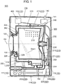
- FIG. 1 is a schematic longitudinal cross-sectional view of a washing machine exemplified as a clothing treatment device of the exemplary embodiment of the present invention.
- washing machine 100 of this exemplary embodiment includes at least: casing 110; and housing tub 200 for housing clothing inside casing 110.
- Housing tub 200 includes rotary drum 210 having peripheral wall 211 which surrounds axis of rotation RX and which has an approximately circular cylindrical shape (including a circular cylindrical shape), and water tub 220 which houses rotary drum 210.
- Casing 110 is constituted of: front wall 111 in which a put-in opening through which clothing is put into housing tub 200 is formed; rear wall 112 disposed opposite to front wall 111; casing ceiling wall 113 which extends approximately horizontally (including horizontally); casing bottom wall 114 disposed opposite to casing ceiling wall 113; a left wall and a right wall described later and the like.
- rotary drum 210 and water tub 220 of housing tub 200 are opened toward front wall 111.
- Washing machine 100 further includes door body 120 which is mounted on front wall 111 of casing 110.
- Door body 120 is rotatable between a closed position where door body 120 closes the put-in opening formed in front wall 111 and an open position where door body 120 opens the put-in opening. Due to such a constitution, a user can put clothing into housing tub 200 through the put-in opening formed in front wall 111 after rotating door body 120 to the open position. Thereafter, the user moves door body 120 to the closed position, and the washing machine 100 washes the clothing already put into washing machine 100.
- FIG. 1 shows a state where door body 120 is at the closed position.
- Rotary drum 210 includes peripheral wall 211 and bottom wall 212, and is rotated about axis of rotation RX which extends between front wall 111 and rear wall 112 of casing 110. Clothing put into housing tub 200 moves inside rotary drum 210 along with the rotation of rotary drum 210. Due to such an operation, clothing is subjected to various processing such as washing processing, rinsing processing and/or spin-drying processing. Bottom wall 212 of rotary drum 210 is disposed in a state where the bottom wall 212 faces door body 120 at the closed position.
- Water tub 220 is constituted of at least bottom portion 221, and front portion 222.
- Bottom portion 221 surrounds bottom wall 212 and a portion of peripheral wall 211 of rotary drum 210.
- Front portion 222 is disposed between bottom portion 221 of water tub 220 and door body 120, and surrounds a remaining portion of peripheral wall 211 of rotary drum 210 which front portion 222 faces.
- Housing tub 200 includes rotary shaft 230 which is mounted on bottom wall 212 of rotary drum 210, and extends toward rear wall 112 of casing 110 along axis of rotation RX. Accordingly, rotary shaft 230 is provided such that rotary shaft 230 penetrates bottom portion 221 of water tub 220 and projects into a space formed between water tub 220 and rear wall 112.
- Washing machine 100 includes motor 231 which is mounted on a lower side of water tub 220, pulley 232 which is mounted on rotary shaft 230 which is exposed to the outside of water tub 220, and belt 233 which transmits power of motor 231 to pulley 232. Further, when motor 231 is operated, power of motor 231 is transmitted to rotary shaft 230 by way of belt 233 and pulley 232. As a result, rotary drum 210 rotates inside water tub 220.
- Washing machine 100 further includes packing structure 130 disposed between front portion 222 of water tub 220 and door body 120.
- packing structure 130 is compressed by door body 120.
- the watertight sealing structure is formed between door body 120 and front portion 222.
- Washing machine 100 includes water supply port 140 which is connected to a faucet (not shown in the drawing), and distribution part 141 for distributing water introduced into washing machine 100 through water supply port 140.
- Water supply port 140 is disposed in a state where the water supply port 140 projects upward from casing ceiling wall 113, and distribution part 141 is disposed between casing ceiling wall 113 and housing tub 200.
- washing machine 100 includes a detergent housing part (not shown in the drawing) in which a detergent is housed, and steam supply mechanism 300 which injects steam to housing tub 200 (described later).
- Distribution part 141 includes a plurality of water supply valves for selectively supplying water to housing tub 200, detergent housing part and steam supply mechanism 300 through water supply passages (not shown in the drawing). It is needless to say that known techniques applied to washing machines are applicable to the supply of water to housing tub 200 and the detergent housing part.
- FIG. 2 is a schematic perspective view of the washing machine of the exemplary embodiment with a part shown in a see-through manner.
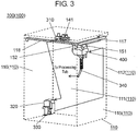
- FIG. 3 is a schematic perspective view of the steam supply mechanism which is housed in the casing of the washing machine of the exemplary embodiment.
- Casing 110 is indicated by a dotted line in FIG. 2 and FIG. 3 , and housing tub 200 is not shown in FIG. 3 .
- An arrow in FIG. 3 schematically shows the water supply passages which connect the respective parts to each other.
- steam supply mechanism 300 includes at least water supply valve 310 which is used as a part of distribution part 141, and water storage tank 320 which is disposed below housing tub 200.
- Water supply valve 310 controls the supply of water to water storage tank 320. That is, when water supply valve 310 is opened, water is supplied to water storage tank 320 from water supply port 140. When water supply valve 310 is closed, the supply of water to water storage tank 320 is stopped.
- Steam supply mechanism 300 further includes pump 330 which is mounted on water storage tank 320, and steam generating part 400 which receives water discharged from pump 330.
- Pump 330 performs an operation to supply water to steam generating part 400 intermittently or continuously. During an intermittent water supply operation, pump 330 supplies a proper amount of water which is adjusted such that steam is generated instantaneously to steam generating part 400 described later.
- water is continuously supplied to steam generating part 400 by pump 330, it is possible to wash away an impurity (scale) or the like contained in water used for steam generation from steam generating part 400.
- steam supply mechanism 300 further includes steam communication tube 340 which extends downward from steam generating part 400.
- front portion 222 of water tub 220 includes peripheral wall portion 223 which surrounds peripheral wall 211 of rotary drum 210, and annular portion 224 shown in FIG. 2 which forms the watertight sealing structure in cooperation with packing structure 130.
- Steam communication tube 340 of steam supply mechanism 300 is connected to peripheral wall portion 223 of front portion 222. Due to such a constitution, steam generated in steam generating part 400 is supplied to housing tub 200 through steam communication tube 340. It is preferable that steam communication tube 340 be formed such that at least a portion of steam communication tube 340 is formed into a bellows shape, for example, so as to prevent vibrations generated by the rotation of housing tub 200 from being transmitted to steam generating part 400.
- steam supply mechanism 300 of this exemplary embodiment it is possible to forcibly supply water to steam generator 420 (see FIG. 8 ) disposed inside steam generating part 400 from water storage tank 320 by pump 330. Accordingly, steam generator 420 can be disposed above water storage tank 320.
- steam generator 420 can be disposed above water storage tank 320.
- steam generator 420 is disposed above water storage tank 320 as shown in FIG. 2 , water can be supplied to steam generator 420 from water storage tank 320 by pump 330 without causing any problems.
- steam generator 420 of steam generating part 400 is disposed above housing tub 200.
- an impurity contained in water supplied to steam generator 420 adheres to or precipitates on a wall surface of chamber space 430 which is defined by outer chamber wall 431, inner chamber wall 432 and upper surface 429 of body portion 423, and lower surface 434 of lid portion 424 which constitute steam generator 420 at the time of evaporating water.
- the impurity is deposited on the wall surface which defines chamber space 430. In this case, the heat transfer between the wall surface of chamber space 430 and supplied water is not performed properly due to the impurity and hence, water supplied to steam generator 420 is minimally evaporated.
- water storage tank 320 is disposed in a left lower space of casing 110, and steam generator 420 is disposed in a right upper space of casing 110. That is, steam generator 420 and water storage tank 320 are disposed at approximately symmetrical positions (including completely symmetrical positions) with respect to the center axis of housing tub 200 (axis of rotation RX).
- a detergent housing part (not shown in the drawing) which houses a detergent is disposed on either a left side or a right side of an upper front portion of casing 110. Accordingly, a space which is defined by casing 110 and housing tub 200 having approximately circular cylindrical shape (including a circular cylindrical shape) excluding a position occupied by the detergent housing part can be effectively used as a space for disposing water storage tank 320 and steam generator 420.
- water storage tank 320 is disposed on a rear side of the left lower portion of casing 110.
- a space defined between an inner surface of casing 110 having an approximately rectangular box shape (including a rectangular box shape) and an outer peripheral surface of housing tub 200 can be effectively used for disposing water storage tank 320 and steam generator 420.
- a design size of water storage tank 320 and a design size of steam generator 420 can be set to values which allow housing of water storage tank 320 and steam generator 420 having maximally large sizes in the space defined in washing machine 100.
- water storage tank 320 may be disposed at a position approximately symmetrical with the detergent housing part with respect to the center axis of housing tub 200 (axis of rotation RX), and steam generator 420 may be disposed at a position approximately symmetrical with water storage tank 320 with respect to horizontal plane HP which includes axis of rotation RX of housing tub 200.
- the space inside casing 110 can be effectively used in the same manner as described above.
- water storage tank 320 may be disposed below the detergent housing part, and steam generator 420 may be disposed above water storage tank 320.
- steam generator 420 may be disposed at a position approximately symmetrical with water storage tank 320 with respect to a vertical plane which includes axis of rotation RX of housing tub 200.
- water storage tank 320 and steam generator 420 may be disposed at approximately symmetrical positions with respect to axis of rotation RX of housing tub 200 or with respect to horizontal plane HP which includes axis of rotation RX.
- water storage tank 320 and steam generator 420 are disposed at approximately symmetrical positions with respect to a vertical plane which passes the approximately center (including the center) in the longitudinal direction of casing 110. Due to such an arrangement, an inner space defined between the inner surface of casing 110 and the outer peripheral surface of housing tub 200 can be effectively used for disposing water storage tank 320 and steam generator 420.
- FIG. 4A and FIG. 4B are schematic perspective views of the steam generating part of the steam supply mechanism of the exemplary embodiment.
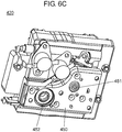
- FIG. 6A to FIG. 6C are schematic perspective views of the steam generator of the steam generating part of the exemplary embodiment.
- steam generating part 400 includes casing 410 having an approximately rectangular box shape (including rectangular box shape), and steam generator 420 which is housed in casing 410.
- Casing 410 includes: vessel portion 411 which has bottom wall portion 414 and houses steam generator 420; and lid portion 412 which is constituted of upper wall 415 covering vessel portion 411 and lid portion peripheral wall 416 on which projecting member 417. Opening portion 413 is formed on bottom wall portion 414 of vessel portion 411.
- Steam generator 420 is connected to pump 330 by way of connection tube 421 and a tube (not shown in the drawing), and is connected to steam communication tube 340 by way of discharge tube 422.
- connection tube 421 and discharge tube 422 of steam generator 420 are fixed to fixing member 450 having an approximately planar shape (a plate shape, for example), and fixing member 450 is fixed to body portion 423 of steam generator 420. Due to such a constitution, connection tube 421 and discharge tube 422 are fixed to steam generator 420 in a stable manner.
- Connection tube 421 and discharge tube 422 are connected away from (in a spaced-apart manner from) steam generator 420 by fixing member 450. Due to such a constitution, it is possible to suppress heat generated by steam generator 420 from being transferred to connection tube 421 and discharge tube 422. As a result, thermal deformation and thermal deterioration of connection tube 421 and discharge tube 422 can be suppressed.
- inlet port 437 (described later) and connection tube 421 are sealed air-tightly by first sealing member 451, and discharge port 438 (described later) and discharge tube 422 are sealed air-tightly by second sealing member 452. Due to such a constitution, it is possible to prevent leakage of steam, water and the like.
- fixing member 450 be made of metal such as iron or stainless steel, for example.
- thermal conductivity of iron or stainless steel which is used for forming fixing member 450 is lower than thermal conductivity of steam generator 420 which is formed using a material such as aluminum, for example. Accordingly, the thermal conduction from body portion 423 (that is, steam generator 420) to fixing member 450 is suppressed. Due to such a constitution, thermal deformation and thermal deterioration of connection tube 421 and discharge tube 422 connected to fixing member 450 can be further suppressed.
- Connection tube 421 and discharge tube 422 fixed to fixing member 450 are disposed so as to project downward through opening portion 413 formed on bottom wall portion 414 of steam generating part 400.
- FIG. 5 the mounting structure for mounting steam generating part 400 of steam supply mechanism 300 on casing 110 of washing machine 100 is described using FIG. 5 by also referencing FIG. 3 and FIG. 4A .
- FIG. 5 is a schematic perspective view of the mounting structure for connecting the lid portion and the casing of the steam generating part of this exemplary embodiment to each other.
- casing 110 is constituted of at least: front wall 111; rear wall 112; right wall 115 which is formed in a raised manner between front wall 111 and rear wall 112; and left wall 116 which is formed opposite to right wall 115.
- Casing 110 further includes first reinforcing frame 117 which is disposed along an upper edge of right wall 115, and second reinforcing frame 118 which is disposed along an upper edge of front wall 111.
- lid portion 412 which forms a portion of steam generating part 400 includes: upper wall 415 having an approximately rectangular shape (including a rectangular shape); lid portion peripheral walls 416 which project downward (toward a casing 410 side) from edge portions of upper wall 415; and projecting member 417 which projects frontward (toward a front wall 111 side of casing 110) from lid portion peripheral wall 416.
- first reinforcing frame 117 which is mounted on casing 110 of washing machine 100 and upper wall 415 of lid portion 412 of steam generating part 400 are connected to each other by first mounting member 151 shown at an upper right side of FIG. 5 .
- second reinforcing frame 118 and projecting member 417 are connected to each other by second mounting member 152 shown at an upper left side of FIG, 5 .
- lid portion 412 of steam generating part 400 and casing ceiling wall 113 of casing 110 are mounted in a spaced-apart manner from each other by way of first mounting member 151 and second mounting member 152 which are mounted on lid portion 412 in an upwardly projecting manner.
- first mounting member 151 and second mounting member 152 which are mounted on lid portion 412 in an upwardly projecting manner.
- steam generator 420 is constituted of : body portion 423 having an approximately rectangular shape (including a rectangular shape); lid portion 424 which is disposed on body portion 423; and a linear heater 425 such as a sheathed heater which is disposed inside body portion 423 through peripheral surface 428 of body portion 423, for example.
- body portion 423 and lid portion 424 are formed using a material such as aluminum, for example, having higher thermal conductivity than a material used for forming fixing member 450 described above. Due to such a constitution, body portion 423 and lid portion 424 are efficiently and properly heated by heater 425.
- thermister 426 is further mounted on body portion lower surface 427 of body portion 423 of steam generator 420.
- connection tube 421 and discharge tube 422 which are fixed to fixing member 450 are also mounted on body portion lower surface 427 of body portion 423 which constitutes steam generator 420.
- Heater 425 is controlled based on temperature information obtained by thermister 426. Due to such a control, a temperature of body portion 428 and a temperature of lid portion 424 are held at approximately fixed temperatures (including fixed temperatures). A thermostat which controls the turning on and off of electricity power to heater 425 at a predetermined temperature may be used in place of thermister 426. In this case, the substantially the same effect can be obtained.
- body portion 423 which constitutes steam generator 420 is described using FIG. 6B and FIG. 7 .
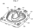
- FIG. 7 is a schematic perspective view of the body portion of the steam generator of this exemplary embodiment.
- body portion 423 includes body portion lower surface 427, peripheral surface 428, and upper surface 429.
- Thermister 426, connection tube 421 and discharge tube 422 are mounted on body portion lower surface 427, wherein connection tube 421 and discharge tube 422 are mounted on body portion lower surface 427 by way of fixing member 450.
- Heater 425 is disposed on peripheral surface 428.
- body portion 423 is formed on upper surface 429 in a raised manner toward lid portion 424 which constitutes one side of steam generator 420 thus forming chamber space 430 having an approximately triangular shape (including a triangular shape), for example.
- Chamber space 430 is formed in such a manner that the chamber space 430 is defined by outer chamber wall 431 and inner chamber wall 432 having an approximately J shape (including a J shape), for example, which defines a steam flow passage inside chamber space 430.
- FIG. 8 is a schematic developed perspective view of the steam generator of this exemplary embodiment.
- FIG. 9 is a schematic perspective view of the lid portion of the steam generator of this exemplary embodiment.
- steam generator 420 includes packing ring 433 made of a heat-resistance rubber or the like, for example, which is mounted on body portion 423 in a state where the steam generator 420 surrounds the outer periphery of outer chamber wall 431.
- lid body 424 includes lower surface 434 which faces body portion 423, and shield wall 435 which has the substantially same shape (including the same shape) as outer chamber wall 431 of body portion 423.
- lid portion 424 By pushing lid portion 424 to body portion 423, shield wall 435 of lid portion 424 compresses packing ring 433. As a result, air-tightness of chamber space 430 of steam generator 420 is maintained.
- Inlet port 437 is formed in body portion 423. Inlet port 437 is formed so as to allow water supplied through connection tube 421 connected to body portion lower surface 427 by way of fixing member 450 to flow into the inside of chamber space 430. Inlet port 437 is formed at the approximately center (including the center) of chamber space 430, and the periphery of inlet port 437 is surrounded by inner chamber wall 432.
- Steam generator 420 of this exemplary embodiment is constituted as described above.
- steam generator 420 when a predetermined amount of water is supplied to steam generator 420 from water storage tank 320 by pump 330, water is injected upward (toward a lid portion 424 side) through connection tube 421 and inlet port 437. Water injected into chamber space 430 of steam generator 420 impinges on inner chamber wall 432, upper surface 429 of body portion 423 surrounded by inner chamber wall 432 and/or lower surface 434 of lid portion 424 which is positioned above inlet port 437. At this point of time, steam generator 420 is heated by heater 425 (for example, approximately 200°C) thus having high thermal energy.
- heater 425 for example, approximately 200°C
- the water supply operation is performed intermittently using pump 330 of steam supply mechanism 300 so that a proper amount of water is supplied into the inside of chamber space 430 of steam generator 420 (for example, approximately 2cc/time). Accordingly, water injected upward from inlet port 437 of steam generator 420 is instantaneously evaporated by thermal energy which steam generator 420 possesses.
- an inner pressure of chamber space 430 is sharply increased.
- An impurity which is contained in water supplied to steam generator 420 adheres to or precipitates on the wall surface which constitutes chamber space 430 when water evaporates.
- the adhered or precipitated impurity receives an action of pressure generated by the sharp rise of an inner pressure of chamber space 430 at the time of evaporation of water. As a result, the impurity is easily discharged outside chamber space 430.
- FIG. 10 is a schematic plan view of the body portion of the steam generator of this exemplary embodiment.
- heater 425 is disposed so as to extend along an approximately U-shape (including a U-shape) passage formed inside body portion 423. Due to such an arrangement, heater 425 surrounds inlet port 437 to which connection tube 421 is mounted. Accordingly, a temperature of inner chamber wall 432 and a temperature of a region surrounded by inner chamber wall 432 become the highest temperature inside chamber space 430 due to heating by heater 425. As a result, water injected into the inside of chamber space 430 through inlet port 437 is instantaneously evaporated.
- Inner chamber wall 432 is disposed inside chamber space 430 defined by outer chamber wall 431 in a state where inner chamber wall 432 extends in an approximately J-shape. That is, a spiral-shaped flow passage is formed in the chamber space 430 by inner chamber wall 432.
- Discharge port 438 is formed in body portion 423 at a position in the vicinity of a terminal end of the flow passage through which water or steam passes. Due to such a constitution, steam generated in the space surrounded by inner chamber wall 432 moves toward discharge port 438 along with the increase of an inner pressure of chamber space 430. Then, steam which arrives at discharge port 438 is discharged downward in the vertical direction through discharge tube 422 mounted on discharge port 438.
- Heater 425 is disposed such that heater 425 extends in an approximately U-shape (including a U-shape) along an outside passage of the spiral-shaped flow passage. Due to such a constitution, steam generated in the space surrounded by inner chamber wall 432 moves toward discharge tube 422 while being heated. Accordingly, high-temperature steam is discharged from discharge tube 422 of steam generator 420.
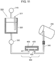
- FIG. 11 the constitution and the operation of the water supply mechanism of the washing machine of the exemplary embodiment of the present invention are described using FIG. 11 .
- FIG. 11 is a schematic view of the water supply mechanism of the steam supply mechanism of this exemplary embodiment.
- water supply mechanism 500 which injects water to chamber space 430 of steam generator 420 includes water supply valve 310, water storage tank 320, pump 330, connection tube 421, water level sensor 321 for measuring a water level in water storage tank 320 and the like all of which are described previously.
- Water supply valve 310 performs the supply of water to water storage tank 320 or the cutting off of the supply of water to water storage tank 320 corresponding to a water level detected by water level sensor 321.
- Water supply valve 310 may be controlled corresponding to an operation time and/or an operation pattern (an intermittent water supply operation and/or a continuous water supply operation) of pump 330. For example, an amount of water supplied from water supply valve 310 may be adjusted such that water storage tank 320 becomes empty when an operation of pump 330 is finished. Due to such a constitution, even when an outside air temperature becomes low, water in water storage tank 320 is minimally frozen. As a result, the reliability of washing machine 100 can be further enhanced.
- Pump 330 supplies water stored inside water storage tank 320 to chamber space 430 of steam generator 420 through connection tube 421.
- a supply amount, a supply time, a supply interval and the like are adjusted such that water injected into the inside of chamber space 430 is instantaneously evaporated.
- Discharge tube 422 of steam generator 420 is connected to steam communication tube 340. Due to such a constitution, steam generated inside chamber space 430 due to the intermittent water supply operation by pump 330 and water which flows inside chamber space 430 due to the continuous water supply operation of pump 330 can be made to flow into the housing tub 200 through discharge tube 422 and steam communication tube 340.
- the water supply mechanism of the steam supply mechanism of washing machine 100 of this exemplary embodiment is configured as described above.
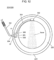
- FIG. 12 the operation of supplying steam and water to be supplied to the housing tub of the washing machine of the exemplary embodiment of the present invention is described using FIG. 12 by also referencing FIG. 1 and FIG. 11 .
- FIG. 12 is a schematic back view of a front portion of the housing tub of the washing machine of this exemplary embodiment.
- annular portion 224 of front portion 222 of water tub 220 includes: inner surface 225 which faces rotary drum 210; and outer surface 226 which faces front wall 111 of casing 110.
- FIG. 12 mainly shows inner surface 225 of annular portion 224 formed on front portion 222 of water tub 220 .
- the above-mentioned steam supply mechanism 300 further includes: branched tube 351 which is mounted on inner surface 225; nozzle 352 which is disposed above branched tube 351; and steam tube 353 which connects branched tube 351 and nozzle 352 to each other.
- Steam communication tube 340 is connected to branched tube 351 through peripheral wall portion 223 of water tub 220.
- steam generated inside chamber space 430 of steam generator 420 flows into steam communication tube 340 through discharge tube 422 along with the increase of a pressure inside chamber space 430. Thereafter, the steam flows into branched tube 351 from steam communication tube 340.
- the steam which arrives at branched tube 351 has a high temperature and hence, the steam is guided to steam tube 353 and flows into nozzle 352 disposed above branched tube 351. Lastly, the steam is injected into the inside of rotary drum 210 of housing tub 200 from nozzle 352.
- steam generated inside chamber space 430 is guided to nozzle 352 through discharge tube 422, steam communication tube 340, branched tube 351 and steam tube 353. That is, pump 330 which performs intermittent water supply operation injects a proper amount of water into the inside of chamber space 430 which is heated by heater 425 and has a high temperature and hence, water is instantaneously evaporated. At this point of time, an inner pressure of chamber space 430 of steam generator 420 is sharply increased due to the evaporation of the water. Accordingly, generated steam is injected from nozzle 352 at a high pressure. As a result, as shown in FIG. 1 and FIG. 12 , steam is injected such that steam traverses an inner space of housing tub 200 in the vertical direction.
- Branched tube 351 which introduces steam into steam tube 353 from steam communication tube 340 includes: main tube 354 which is connected to steam communication tube 340; upper sub tube 355 which is bent upward from main tube 354; and lower sub tube 356 which is bent downward from main tube 354. Steam or water flows into main tube 354 through steam communication tube 340. Upper sub tube 355 is connected to steam tube 353, and forms an upwardly extending passage through which steam moves toward nozzle 352.
- lower sub tube 356 forms a downwardly extending passage.
- the continuous water supply operation is performed by pump 330, mainly water flows into branched tube 351 through steam communication tube 340. Then, water which flows into branched tube 351 flows downward through lower sub tube 356 due to the action of gravity.
- main tube 354 and upper sub tube 355 of branched tube 351 are connected to each other at an included angle of ⁇ 1 which is an obtuse angle, while main tube 354 and lower sub tube 356 are connected to each other at an included angle of ⁇ 2 which is an acute angle. Since the included angle ⁇ 2 is an acute angle, a flow loss from main tube 354 to lower sub tube 356 is relatively large. Accordingly, steam which flows into the inside of main tube 354 minimally flows into lower sub tube 356, and the steam mainly flows into upper sub tube 355.
- upper sub tube 355 forms the upwardly extending flow passage and hence, due to the action of gravity, water which flows into main tube 354 minimally flows into upper sub tube 355 and the water mainly flows into lower sub tube 356.
- the flow passage for steam and the flow passage for water can be properly separated from each other by branched tube 351.
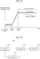
- FIG. 13 the intermittent operation of the pump which supplies water to the steam generating part of the washing machine of the exemplary embodiment of the present invention is described using FIG. 13 by also referencing FIG. 8 and FIG. 11 .
- FIG. 13 is an explanatory view schematically showing the relationship between an intermittent operation by the pump of the water supply mechanism and a temperature inside the chamber space in the exemplary embodiment.
- a period during which pump 330 is operated is set shorter than a period during which pump 330 is stopped (OFF period). Accordingly, a proper amount of water can be injected into the inside of chamber space 430 of steam generator 420 in steam generating part 400. It is needless to say that a length of the ON period and a length of the OFF period in Fig. 13 are relative values, and these lengths may be changed corresponding to a capacity of chamber space 430, an amount of heating by the heater, and a required amount of steam.
- pump 330 supplies a predetermined amount of water to chamber space 430 in the ON period.
- the supplied water is evaporated so as to generate steam.
- a temperature in chamber space 430 is temporarily lowered.
- heater 425 can sufficiently increase a temperature in chamber space 430 during the OFF period. As a result, it is possible to continue the supply of high-pressure steam to housing tub 200 during a period where pump 330 performs the intermittent operation.
- a temperature in chamber space 430 is sufficiently increased during the OFF period. Then, in the ON period, a proper amount of water which can be evaporated instantaneously by thermal energy which steam generator 420 including chamber space 430 possesses is supplied to chamber space 430 (for example, approximately 2cc/time). Accordingly, it is possible to favorably continue the supply of high-pressure steam to housing tub 200.
- FIG. 14 is an explanatory view schematically showing a temperature change in water supplied to the water tub of the washing machine of the exemplary embodiment.
- hot water heater 160 for heating water supplied to the inside of water tub 220 is disposed in a lower portion of water tub 220.
- a predetermined amount of water is supplied to water tub 220.
- a temperature of water contained in clothing inside water tub 220 takes an approximately fixed value (including a fixed value).
- hot water heater 160 generates a large amount of heat value and hence, a temperature of water contained in clothing inside water tub 220 is sharply increased.
- a temperature of water reaches a predetermined temperature, heating of water inside water tub 220 is stopped.
- washing step is carried out by introducing steam into the inside of housing tub 200 through steam supply mechanism 300.
- a dotted line after heating is stopped shown in FIG. 14 indicates a change in temperature of water contained in clothing when the heating by hot water heater 160 is stopped so that steam is not supplied.
- a solid line after heating is stopped indicates a change in temperature of water contained in clothing when heating by hot water heater 160 is stopped so that steam is supplied to housing tub 200.
- high-temperature steam is directly supplied to housing tub 200 in a state where the steam is injected to clothing. Accordingly, lowering of a temperature of water contained in clothing inside water tub 220 is alleviated (suppressed) by high-temperature steam. Further, power consumption of heater 425 used in steam generator 420 is smaller than that of hot water heater 160 mounted on water tub 220. As a result, heat retention by the supply of high-temperature steam can be realized with low power consumption compared to the case where heat retention of water inside water tub 220 is performed using hot water heater 160. Accordingly, in washing step, it is preferable that high-temperature steam be supplied to the housing tub by performing intermittent water supply operation using pump 330 after hot water heater 160 is stopped.
- rotary drum 210 is rotated at a high speed by motor 231. As shown in FIG. 1 , a large number of small holes 219 are formed in peripheral wall 211 of rotary drum 210.
- steam is supplied to the inside of rotary drum 210 in spin-drying step. Due to such supply of steam, hydrogen bonding of fibers can be released by steam. As a result, the generation of wrinkles in clothing can be decreased.
- step of cooling the steam generator of the exemplary embodiment of the present invention is described using FIG. 8 and FIG. 11 .
- FIG. 15 a control of the door body of the exemplary embodiment of the present invention is described using FIG. 15 by also referencing FIG. 1 and FIG. 6B .
- Such a control is performed for preventing door body 120 from being inadvertently opened by a user when high-temperature steam is present inside housing tub 200.
- FIG. 15 is a block diagram schematically showing the control of the door body based on a temperature of the steam generator of this exemplary embodiment.
- washing machine 100 of this exemplary embodiment includes: locking mechanism 121 which locks door body 120 at a closed position; and control part 122 for controlling locking using locking mechanism 121 and releasing of such locking. It is needless to say that the known structures of washing machines are utilized as mechanical and electric mechanisms used in locking mechanism 121.
- steam generator 420 includes thermister 426.
- thermister 426 detects a temperature of body portion 423 of steam generator 420, and outputs a signal corresponding to a detected temperature to control part 122.
- control part 122 maintains locking of door body 120 using locking mechanism 121 until a signal outputted from thermister 426 becomes a signal corresponding to a predetermined temperature or below. Due to such an operation, until a temperature of steam generator 420 becomes a predetermined temperature or below, the inner space of housing tub 200 is isolated from the outside. As a result, it is possible to prevent a user from being exposed to high-temperature steam in advance thus realizing safe and highly reliable washing machine 100.
- the present invention is preferably applicable to a device which processes clothing using steam.
Priority Applications (1)
| Application Number | Priority Date | Filing Date | Title |
|---|---|---|---|
| SI201330876T SI2865802T1 (en) | 2012-06-22 | 2013-06-18 | Machine for working clothes |
Applications Claiming Priority (2)
| Application Number | Priority Date | Filing Date | Title |
|---|---|---|---|
| JP2012140490A JP2014004056A (ja) | 2012-06-22 | 2012-06-22 | 衣類処理装置 |
| PCT/JP2013/003778 WO2013190825A1 (ja) | 2012-06-22 | 2013-06-18 | 衣類処理装置 |
Publications (3)
| Publication Number | Publication Date |
|---|---|
| EP2865802A1 EP2865802A1 (en) | 2015-04-29 |
| EP2865802A4 EP2865802A4 (en) | 2015-07-22 |
| EP2865802B1 true EP2865802B1 (en) | 2017-09-06 |
Family
ID=49768439
Family Applications (1)
| Application Number | Title | Priority Date | Filing Date |
|---|---|---|---|
| EP13807448.9A Active EP2865802B1 (en) | 2012-06-22 | 2013-06-18 | Clothing treatment device |
Country Status (5)
| Country | Link |
|---|---|
| EP (1) | EP2865802B1 (ja) |
| JP (1) | JP2014004056A (ja) |
| CN (1) | CN104508198B (ja) |
| SI (1) | SI2865802T1 (ja) |
| WO (1) | WO2013190825A1 (ja) |
Families Citing this family (1)
| Publication number | Priority date | Publication date | Assignee | Title |
|---|---|---|---|---|
| CN114045635A (zh) * | 2021-11-30 | 2022-02-15 | 珠海格力电器股份有限公司 | 一种用于衣物处理装置的蒸汽发生器、衣物处理装置 |
Family Cites Families (11)
| Publication number | Priority date | Publication date | Assignee | Title |
|---|---|---|---|---|
| KR20060120824A (ko) * | 2005-05-23 | 2006-11-28 | 엘지전자 주식회사 | 세탁기용 스팀발생장치의 체결구조 |
| JP4927075B2 (ja) | 2005-05-23 | 2012-05-09 | エルジー エレクトロニクス インコーポレイティド | ドラム洗濯機のスチーム発生装置の水位センサー構造 |
| KR101139250B1 (ko) * | 2006-01-26 | 2012-05-14 | 삼성전자주식회사 | 증기발생장치를 갖춘 세탁기 및 그 제어방법 |
| KR20070078328A (ko) * | 2006-01-26 | 2007-07-31 | 엘지전자 주식회사 | 스팀발생장치 및 이를 이용한 세탁기 |
| JP2008075903A (ja) * | 2006-09-19 | 2008-04-03 | Rinnai Corp | 配管接続具の取付構造 |
| JP2009213693A (ja) * | 2008-03-11 | 2009-09-24 | Toshiba Corp | ドラム式洗濯機 |
| JP2011092540A (ja) * | 2009-10-30 | 2011-05-12 | Sharp Corp | 洗濯機 |
| US9074311B2 (en) * | 2010-03-12 | 2015-07-07 | Lg Electronics Inc. | Steam generator and washing machine having the same |
| KR101017982B1 (ko) * | 2010-07-15 | 2011-03-02 | 임주혁 | 자체증기압력을 이용한 자동 급수식 증기발생장치 |
| JP2013252237A (ja) * | 2012-06-06 | 2013-12-19 | Panasonic Corp | 衣類処理装置 |
| JP2013252240A (ja) * | 2012-06-06 | 2013-12-19 | Panasonic Corp | 衣類処理装置 |
-
2012
- 2012-06-22 JP JP2012140490A patent/JP2014004056A/ja active Pending
-
2013
- 2013-06-18 SI SI201330876T patent/SI2865802T1/en unknown
- 2013-06-18 WO PCT/JP2013/003778 patent/WO2013190825A1/ja active Application Filing
- 2013-06-18 CN CN201380032057.3A patent/CN104508198B/zh active Active
- 2013-06-18 EP EP13807448.9A patent/EP2865802B1/en active Active
Non-Patent Citations (1)
| Title |
|---|
| None * |
Also Published As
| Publication number | Publication date |
|---|---|
| WO2013190825A1 (ja) | 2013-12-27 |
| CN104508198A (zh) | 2015-04-08 |
| JP2014004056A (ja) | 2014-01-16 |
| SI2865802T1 (en) | 2018-01-31 |
| EP2865802A4 (en) | 2015-07-22 |
| CN104508198B (zh) | 2017-04-05 |
| EP2865802A1 (en) | 2015-04-29 |
Similar Documents
| Publication | Publication Date | Title |
|---|---|---|
| EP2889414B1 (en) | Clothes treatment device | |
| EP2865802B1 (en) | Clothing treatment device | |
| EP2840180B1 (en) | Clothing treatment device | |
| WO2013183259A1 (ja) | 衣類処理装置 | |
| WO2013183256A1 (ja) | 衣類処理装置 | |
| AU2012374621B2 (en) | Clothes treatment device | |
| AU2012374620B2 (en) | Laundry Processing Apparatus | |
| EP2662484B1 (en) | Clothing treatment device | |
| EP2883989B1 (en) | Clothes treatment device | |
| EP2832915B1 (en) | Laundry processing apparatus | |
| EP2832914B1 (en) | Clothes treatment device | |
| JP2014004054A (ja) | 衣類処理装置 | |
| JP2014042701A (ja) | 衣類処理装置 | |
| EP2832913B1 (en) | Clothes treatment device | |
| JP2014004062A (ja) | 衣類処理装置 | |
| JP2017029499A (ja) | 衣類処理装置 | |
| JP2014023674A (ja) | 衣類処理装置 |
Legal Events
| Date | Code | Title | Description |
|---|---|---|---|
| PUAI | Public reference made under article 153(3) epc to a published international application that has entered the european phase |
Free format text: ORIGINAL CODE: 0009012 |
|
| 17P | Request for examination filed |
Effective date: 20141113 |
|
| AK | Designated contracting states |
Kind code of ref document: A1 Designated state(s): AL AT BE BG CH CY CZ DE DK EE ES FI FR GB GR HR HU IE IS IT LI LT LU LV MC MK MT NL NO PL PT RO RS SE SI SK SM TR |
|
| AX | Request for extension of the european patent |
Extension state: BA ME |
|
| RA4 | Supplementary search report drawn up and despatched (corrected) |
Effective date: 20150618 |
|
| RIC1 | Information provided on ipc code assigned before grant |
Ipc: D06F 25/00 20060101ALI20150612BHEP Ipc: D06F 33/02 20060101ALI20150612BHEP Ipc: D06F 58/02 20060101ALI20150612BHEP Ipc: D06F 39/04 20060101AFI20150612BHEP |
|
| DAX | Request for extension of the european patent (deleted) | ||
| 17Q | First examination report despatched |
Effective date: 20160210 |
|
| GRAP | Despatch of communication of intention to grant a patent |
Free format text: ORIGINAL CODE: EPIDOSNIGR1 |
|
| INTG | Intention to grant announced |
Effective date: 20170103 |
|
| GRAS | Grant fee paid |
Free format text: ORIGINAL CODE: EPIDOSNIGR3 |
|
| GRAJ | Information related to disapproval of communication of intention to grant by the applicant or resumption of examination proceedings by the epo deleted |
Free format text: ORIGINAL CODE: EPIDOSDIGR1 |
|
| GRAL | Information related to payment of fee for publishing/printing deleted |
Free format text: ORIGINAL CODE: EPIDOSDIGR3 |
|
| REG | Reference to a national code |
Ref country code: DE Ref legal event code: R079 Ref document number: 602013026296 Country of ref document: DE Free format text: PREVIOUS MAIN CLASS: D06F0039040000 Ipc: D06F0039000000 |
|
| GRAP | Despatch of communication of intention to grant a patent |
Free format text: ORIGINAL CODE: EPIDOSNIGR1 |
|
| INTC | Intention to grant announced (deleted) | ||
| RIC1 | Information provided on ipc code assigned before grant |
Ipc: D06F 25/00 20060101ALI20170511BHEP Ipc: D06F 39/00 20060101AFI20170511BHEP Ipc: D06F 58/20 20060101ALI20170511BHEP |
|
| INTG | Intention to grant announced |
Effective date: 20170531 |
|
| GRAA | (expected) grant |
Free format text: ORIGINAL CODE: 0009210 |
|
| AK | Designated contracting states |
Kind code of ref document: B1 Designated state(s): AL AT BE BG CH CY CZ DE DK EE ES FI FR GB GR HR HU IE IS IT LI LT LU LV MC MK MT NL NO PL PT RO RS SE SI SK SM TR |
|
| REG | Reference to a national code |
Ref country code: GB Ref legal event code: FG4D |
|
| REG | Reference to a national code |
Ref country code: CH Ref legal event code: EP Ref country code: AT Ref legal event code: REF Ref document number: 926057 Country of ref document: AT Kind code of ref document: T Effective date: 20170915 |
|
| REG | Reference to a national code |
Ref country code: IE Ref legal event code: FG4D |
|
| REG | Reference to a national code |
Ref country code: DE Ref legal event code: R096 Ref document number: 602013026296 Country of ref document: DE |
|
| REG | Reference to a national code |
Ref country code: NL Ref legal event code: MP Effective date: 20170906 |
|
| REG | Reference to a national code |
Ref country code: LT Ref legal event code: MG4D |
|
| PG25 | Lapsed in a contracting state [announced via postgrant information from national office to epo] |
Ref country code: FI Free format text: LAPSE BECAUSE OF FAILURE TO SUBMIT A TRANSLATION OF THE DESCRIPTION OR TO PAY THE FEE WITHIN THE PRESCRIBED TIME-LIMIT Effective date: 20170906 Ref country code: NO Free format text: LAPSE BECAUSE OF FAILURE TO SUBMIT A TRANSLATION OF THE DESCRIPTION OR TO PAY THE FEE WITHIN THE PRESCRIBED TIME-LIMIT Effective date: 20171206 Ref country code: HR Free format text: LAPSE BECAUSE OF FAILURE TO SUBMIT A TRANSLATION OF THE DESCRIPTION OR TO PAY THE FEE WITHIN THE PRESCRIBED TIME-LIMIT Effective date: 20170906 Ref country code: SE Free format text: LAPSE BECAUSE OF FAILURE TO SUBMIT A TRANSLATION OF THE DESCRIPTION OR TO PAY THE FEE WITHIN THE PRESCRIBED TIME-LIMIT Effective date: 20170906 Ref country code: LT Free format text: LAPSE BECAUSE OF FAILURE TO SUBMIT A TRANSLATION OF THE DESCRIPTION OR TO PAY THE FEE WITHIN THE PRESCRIBED TIME-LIMIT Effective date: 20170906 |
|
| REG | Reference to a national code |
Ref country code: AT Ref legal event code: MK05 Ref document number: 926057 Country of ref document: AT Kind code of ref document: T Effective date: 20170906 |
|
| PG25 | Lapsed in a contracting state [announced via postgrant information from national office to epo] |
Ref country code: LV Free format text: LAPSE BECAUSE OF FAILURE TO SUBMIT A TRANSLATION OF THE DESCRIPTION OR TO PAY THE FEE WITHIN THE PRESCRIBED TIME-LIMIT Effective date: 20170906 Ref country code: RS Free format text: LAPSE BECAUSE OF FAILURE TO SUBMIT A TRANSLATION OF THE DESCRIPTION OR TO PAY THE FEE WITHIN THE PRESCRIBED TIME-LIMIT Effective date: 20170906 Ref country code: ES Free format text: LAPSE BECAUSE OF FAILURE TO SUBMIT A TRANSLATION OF THE DESCRIPTION OR TO PAY THE FEE WITHIN THE PRESCRIBED TIME-LIMIT Effective date: 20170906 Ref country code: GR Free format text: LAPSE BECAUSE OF FAILURE TO SUBMIT A TRANSLATION OF THE DESCRIPTION OR TO PAY THE FEE WITHIN THE PRESCRIBED TIME-LIMIT Effective date: 20171207 Ref country code: BG Free format text: LAPSE BECAUSE OF FAILURE TO SUBMIT A TRANSLATION OF THE DESCRIPTION OR TO PAY THE FEE WITHIN THE PRESCRIBED TIME-LIMIT Effective date: 20171206 |
|
| PG25 | Lapsed in a contracting state [announced via postgrant information from national office to epo] |
Ref country code: NL Free format text: LAPSE BECAUSE OF FAILURE TO SUBMIT A TRANSLATION OF THE DESCRIPTION OR TO PAY THE FEE WITHIN THE PRESCRIBED TIME-LIMIT Effective date: 20170906 |
|
| PG25 | Lapsed in a contracting state [announced via postgrant information from national office to epo] |
Ref country code: CZ Free format text: LAPSE BECAUSE OF FAILURE TO SUBMIT A TRANSLATION OF THE DESCRIPTION OR TO PAY THE FEE WITHIN THE PRESCRIBED TIME-LIMIT Effective date: 20170906 Ref country code: RO Free format text: LAPSE BECAUSE OF FAILURE TO SUBMIT A TRANSLATION OF THE DESCRIPTION OR TO PAY THE FEE WITHIN THE PRESCRIBED TIME-LIMIT Effective date: 20170906 Ref country code: PL Free format text: LAPSE BECAUSE OF FAILURE TO SUBMIT A TRANSLATION OF THE DESCRIPTION OR TO PAY THE FEE WITHIN THE PRESCRIBED TIME-LIMIT Effective date: 20170906 |
|
| PG25 | Lapsed in a contracting state [announced via postgrant information from national office to epo] |
Ref country code: IS Free format text: LAPSE BECAUSE OF FAILURE TO SUBMIT A TRANSLATION OF THE DESCRIPTION OR TO PAY THE FEE WITHIN THE PRESCRIBED TIME-LIMIT Effective date: 20180106 Ref country code: SM Free format text: LAPSE BECAUSE OF FAILURE TO SUBMIT A TRANSLATION OF THE DESCRIPTION OR TO PAY THE FEE WITHIN THE PRESCRIBED TIME-LIMIT Effective date: 20170906 Ref country code: AT Free format text: LAPSE BECAUSE OF FAILURE TO SUBMIT A TRANSLATION OF THE DESCRIPTION OR TO PAY THE FEE WITHIN THE PRESCRIBED TIME-LIMIT Effective date: 20170906 Ref country code: EE Free format text: LAPSE BECAUSE OF FAILURE TO SUBMIT A TRANSLATION OF THE DESCRIPTION OR TO PAY THE FEE WITHIN THE PRESCRIBED TIME-LIMIT Effective date: 20170906 Ref country code: SK Free format text: LAPSE BECAUSE OF FAILURE TO SUBMIT A TRANSLATION OF THE DESCRIPTION OR TO PAY THE FEE WITHIN THE PRESCRIBED TIME-LIMIT Effective date: 20170906 Ref country code: IT Free format text: LAPSE BECAUSE OF FAILURE TO SUBMIT A TRANSLATION OF THE DESCRIPTION OR TO PAY THE FEE WITHIN THE PRESCRIBED TIME-LIMIT Effective date: 20170906 |
|
| REG | Reference to a national code |
Ref country code: DE Ref legal event code: R097 Ref document number: 602013026296 Country of ref document: DE |
|
| PLBE | No opposition filed within time limit |
Free format text: ORIGINAL CODE: 0009261 |
|
| STAA | Information on the status of an ep patent application or granted ep patent |
Free format text: STATUS: NO OPPOSITION FILED WITHIN TIME LIMIT |
|
| PG25 | Lapsed in a contracting state [announced via postgrant information from national office to epo] |
Ref country code: DK Free format text: LAPSE BECAUSE OF FAILURE TO SUBMIT A TRANSLATION OF THE DESCRIPTION OR TO PAY THE FEE WITHIN THE PRESCRIBED TIME-LIMIT Effective date: 20170906 |
|
| 26N | No opposition filed |
Effective date: 20180607 |
|
| PGFP | Annual fee paid to national office [announced via postgrant information from national office to epo] |
Ref country code: SI Payment date: 20180531 Year of fee payment: 6 |
|
| PGFP | Annual fee paid to national office [announced via postgrant information from national office to epo] |
Ref country code: GB Payment date: 20180620 Year of fee payment: 6 |
|
| REG | Reference to a national code |
Ref country code: CH Ref legal event code: PL |
|
| REG | Reference to a national code |
Ref country code: BE Ref legal event code: MM Effective date: 20180630 |
|
| REG | Reference to a national code |
Ref country code: IE Ref legal event code: MM4A |
|
| PG25 | Lapsed in a contracting state [announced via postgrant information from national office to epo] |
Ref country code: LU Free format text: LAPSE BECAUSE OF NON-PAYMENT OF DUE FEES Effective date: 20180618 Ref country code: MC Free format text: LAPSE BECAUSE OF FAILURE TO SUBMIT A TRANSLATION OF THE DESCRIPTION OR TO PAY THE FEE WITHIN THE PRESCRIBED TIME-LIMIT Effective date: 20170906 |
|
| PG25 | Lapsed in a contracting state [announced via postgrant information from national office to epo] |
Ref country code: CH Free format text: LAPSE BECAUSE OF NON-PAYMENT OF DUE FEES Effective date: 20180630 Ref country code: LI Free format text: LAPSE BECAUSE OF NON-PAYMENT OF DUE FEES Effective date: 20180630 Ref country code: FR Free format text: LAPSE BECAUSE OF NON-PAYMENT OF DUE FEES Effective date: 20180630 Ref country code: IE Free format text: LAPSE BECAUSE OF NON-PAYMENT OF DUE FEES Effective date: 20180618 |
|
| PG25 | Lapsed in a contracting state [announced via postgrant information from national office to epo] |
Ref country code: BE Free format text: LAPSE BECAUSE OF NON-PAYMENT OF DUE FEES Effective date: 20180630 |
|
| PG25 | Lapsed in a contracting state [announced via postgrant information from national office to epo] |
Ref country code: MT Free format text: LAPSE BECAUSE OF NON-PAYMENT OF DUE FEES Effective date: 20180618 |
|
| GBPC | Gb: european patent ceased through non-payment of renewal fee |
Effective date: 20190618 |
|
| PG25 | Lapsed in a contracting state [announced via postgrant information from national office to epo] |
Ref country code: TR Free format text: LAPSE BECAUSE OF FAILURE TO SUBMIT A TRANSLATION OF THE DESCRIPTION OR TO PAY THE FEE WITHIN THE PRESCRIBED TIME-LIMIT Effective date: 20170906 |
|
| REG | Reference to a national code |
Ref country code: SI Ref legal event code: KO00 Effective date: 20200206 |
|
| PG25 | Lapsed in a contracting state [announced via postgrant information from national office to epo] |
Ref country code: GB Free format text: LAPSE BECAUSE OF NON-PAYMENT OF DUE FEES Effective date: 20190618 |
|
| PG25 | Lapsed in a contracting state [announced via postgrant information from national office to epo] |
Ref country code: SI Free format text: LAPSE BECAUSE OF NON-PAYMENT OF DUE FEES Effective date: 20190619 Ref country code: PT Free format text: LAPSE BECAUSE OF FAILURE TO SUBMIT A TRANSLATION OF THE DESCRIPTION OR TO PAY THE FEE WITHIN THE PRESCRIBED TIME-LIMIT Effective date: 20170906 |
|
| PG25 | Lapsed in a contracting state [announced via postgrant information from national office to epo] |
Ref country code: CY Free format text: LAPSE BECAUSE OF FAILURE TO SUBMIT A TRANSLATION OF THE DESCRIPTION OR TO PAY THE FEE WITHIN THE PRESCRIBED TIME-LIMIT Effective date: 20170906 Ref country code: MK Free format text: LAPSE BECAUSE OF NON-PAYMENT OF DUE FEES Effective date: 20170906 Ref country code: HU Free format text: LAPSE BECAUSE OF FAILURE TO SUBMIT A TRANSLATION OF THE DESCRIPTION OR TO PAY THE FEE WITHIN THE PRESCRIBED TIME-LIMIT; INVALID AB INITIO Effective date: 20130618 |
|
| PG25 | Lapsed in a contracting state [announced via postgrant information from national office to epo] |
Ref country code: AL Free format text: LAPSE BECAUSE OF FAILURE TO SUBMIT A TRANSLATION OF THE DESCRIPTION OR TO PAY THE FEE WITHIN THE PRESCRIBED TIME-LIMIT Effective date: 20170906 |
|
| PGFP | Annual fee paid to national office [announced via postgrant information from national office to epo] |
Ref country code: DE Payment date: 20230620 Year of fee payment: 11 |