WO2013187399A1 - 繊維強化プラスチックの成形方法及びその成形装置 - Google Patents
繊維強化プラスチックの成形方法及びその成形装置 Download PDFInfo
- Publication number
- WO2013187399A1 WO2013187399A1 PCT/JP2013/066059 JP2013066059W WO2013187399A1 WO 2013187399 A1 WO2013187399 A1 WO 2013187399A1 JP 2013066059 W JP2013066059 W JP 2013066059W WO 2013187399 A1 WO2013187399 A1 WO 2013187399A1
- Authority
- WO
- WIPO (PCT)
- Prior art keywords
- molding
- mold
- core
- reinforced plastic
- fiber
- Prior art date
Links
Images


Classifications
-
- B—PERFORMING OPERATIONS; TRANSPORTING
- B29—WORKING OF PLASTICS; WORKING OF SUBSTANCES IN A PLASTIC STATE IN GENERAL
- B29C—SHAPING OR JOINING OF PLASTICS; SHAPING OF MATERIAL IN A PLASTIC STATE, NOT OTHERWISE PROVIDED FOR; AFTER-TREATMENT OF THE SHAPED PRODUCTS, e.g. REPAIRING
- B29C43/00—Compression moulding, i.e. applying external pressure to flow the moulding material; Apparatus therefor
- B29C43/02—Compression moulding, i.e. applying external pressure to flow the moulding material; Apparatus therefor of articles of definite length, i.e. discrete articles
- B29C43/18—Compression moulding, i.e. applying external pressure to flow the moulding material; Apparatus therefor of articles of definite length, i.e. discrete articles incorporating preformed parts or layers, e.g. compression moulding around inserts or for coating articles
-
- B—PERFORMING OPERATIONS; TRANSPORTING
- B29—WORKING OF PLASTICS; WORKING OF SUBSTANCES IN A PLASTIC STATE IN GENERAL
- B29C—SHAPING OR JOINING OF PLASTICS; SHAPING OF MATERIAL IN A PLASTIC STATE, NOT OTHERWISE PROVIDED FOR; AFTER-TREATMENT OF THE SHAPED PRODUCTS, e.g. REPAIRING
- B29C70/00—Shaping composites, i.e. plastics material comprising reinforcements, fillers or preformed parts, e.g. inserts
- B29C70/04—Shaping composites, i.e. plastics material comprising reinforcements, fillers or preformed parts, e.g. inserts comprising reinforcements only, e.g. self-reinforcing plastics
- B29C70/28—Shaping operations therefor
-
- B—PERFORMING OPERATIONS; TRANSPORTING
- B29—WORKING OF PLASTICS; WORKING OF SUBSTANCES IN A PLASTIC STATE IN GENERAL
- B29C—SHAPING OR JOINING OF PLASTICS; SHAPING OF MATERIAL IN A PLASTIC STATE, NOT OTHERWISE PROVIDED FOR; AFTER-TREATMENT OF THE SHAPED PRODUCTS, e.g. REPAIRING
- B29C33/00—Moulds or cores; Details thereof or accessories therefor
- B29C33/44—Moulds or cores; Details thereof or accessories therefor with means for, or specially constructed to facilitate, the removal of articles, e.g. of undercut articles
- B29C33/54—Moulds or cores; Details thereof or accessories therefor with means for, or specially constructed to facilitate, the removal of articles, e.g. of undercut articles made of powdered or granular material
-
- B—PERFORMING OPERATIONS; TRANSPORTING
- B29—WORKING OF PLASTICS; WORKING OF SUBSTANCES IN A PLASTIC STATE IN GENERAL
- B29C—SHAPING OR JOINING OF PLASTICS; SHAPING OF MATERIAL IN A PLASTIC STATE, NOT OTHERWISE PROVIDED FOR; AFTER-TREATMENT OF THE SHAPED PRODUCTS, e.g. REPAIRING
- B29C43/00—Compression moulding, i.e. applying external pressure to flow the moulding material; Apparatus therefor
- B29C43/02—Compression moulding, i.e. applying external pressure to flow the moulding material; Apparatus therefor of articles of definite length, i.e. discrete articles
- B29C43/10—Isostatic pressing, i.e. using non-rigid pressure-exerting members against rigid parts or dies
-
- B—PERFORMING OPERATIONS; TRANSPORTING
- B29—WORKING OF PLASTICS; WORKING OF SUBSTANCES IN A PLASTIC STATE IN GENERAL
- B29C—SHAPING OR JOINING OF PLASTICS; SHAPING OF MATERIAL IN A PLASTIC STATE, NOT OTHERWISE PROVIDED FOR; AFTER-TREATMENT OF THE SHAPED PRODUCTS, e.g. REPAIRING
- B29C43/00—Compression moulding, i.e. applying external pressure to flow the moulding material; Apparatus therefor
- B29C43/32—Component parts, details or accessories; Auxiliary operations
- B29C43/36—Moulds for making articles of definite length, i.e. discrete articles
- B29C43/3642—Bags, bleeder sheets or cauls for isostatic pressing
-
- B—PERFORMING OPERATIONS; TRANSPORTING
- B29—WORKING OF PLASTICS; WORKING OF SUBSTANCES IN A PLASTIC STATE IN GENERAL
- B29C—SHAPING OR JOINING OF PLASTICS; SHAPING OF MATERIAL IN A PLASTIC STATE, NOT OTHERWISE PROVIDED FOR; AFTER-TREATMENT OF THE SHAPED PRODUCTS, e.g. REPAIRING
- B29C70/00—Shaping composites, i.e. plastics material comprising reinforcements, fillers or preformed parts, e.g. inserts
- B29C70/02—Shaping composites, i.e. plastics material comprising reinforcements, fillers or preformed parts, e.g. inserts comprising combinations of reinforcements, e.g. non-specified reinforcements, fibrous reinforcing inserts and fillers, e.g. particulate fillers, incorporated in matrix material, forming one or more layers and with or without non-reinforced or non-filled layers
- B29C70/021—Combinations of fibrous reinforcement and non-fibrous material
-
- B—PERFORMING OPERATIONS; TRANSPORTING
- B29—WORKING OF PLASTICS; WORKING OF SUBSTANCES IN A PLASTIC STATE IN GENERAL
- B29C—SHAPING OR JOINING OF PLASTICS; SHAPING OF MATERIAL IN A PLASTIC STATE, NOT OTHERWISE PROVIDED FOR; AFTER-TREATMENT OF THE SHAPED PRODUCTS, e.g. REPAIRING
- B29C70/00—Shaping composites, i.e. plastics material comprising reinforcements, fillers or preformed parts, e.g. inserts
- B29C70/04—Shaping composites, i.e. plastics material comprising reinforcements, fillers or preformed parts, e.g. inserts comprising reinforcements only, e.g. self-reinforcing plastics
- B29C70/28—Shaping operations therefor
- B29C70/40—Shaping or impregnating by compression not applied
- B29C70/42—Shaping or impregnating by compression not applied for producing articles of definite length, i.e. discrete articles
- B29C70/44—Shaping or impregnating by compression not applied for producing articles of definite length, i.e. discrete articles using isostatic pressure, e.g. pressure difference-moulding, vacuum bag-moulding, autoclave-moulding or expanding rubber-moulding
-
- B—PERFORMING OPERATIONS; TRANSPORTING
- B29—WORKING OF PLASTICS; WORKING OF SUBSTANCES IN A PLASTIC STATE IN GENERAL
- B29C—SHAPING OR JOINING OF PLASTICS; SHAPING OF MATERIAL IN A PLASTIC STATE, NOT OTHERWISE PROVIDED FOR; AFTER-TREATMENT OF THE SHAPED PRODUCTS, e.g. REPAIRING
- B29C70/00—Shaping composites, i.e. plastics material comprising reinforcements, fillers or preformed parts, e.g. inserts
- B29C70/04—Shaping composites, i.e. plastics material comprising reinforcements, fillers or preformed parts, e.g. inserts comprising reinforcements only, e.g. self-reinforcing plastics
- B29C70/28—Shaping operations therefor
- B29C70/40—Shaping or impregnating by compression not applied
- B29C70/42—Shaping or impregnating by compression not applied for producing articles of definite length, i.e. discrete articles
- B29C70/46—Shaping or impregnating by compression not applied for producing articles of definite length, i.e. discrete articles using matched moulds, e.g. for deforming sheet moulding compounds [SMC] or prepregs
- B29C70/461—Rigid movable compressing mould parts acting independently from opening or closing action of the main mould
-
- B—PERFORMING OPERATIONS; TRANSPORTING
- B29—WORKING OF PLASTICS; WORKING OF SUBSTANCES IN A PLASTIC STATE IN GENERAL
- B29C—SHAPING OR JOINING OF PLASTICS; SHAPING OF MATERIAL IN A PLASTIC STATE, NOT OTHERWISE PROVIDED FOR; AFTER-TREATMENT OF THE SHAPED PRODUCTS, e.g. REPAIRING
- B29C70/00—Shaping composites, i.e. plastics material comprising reinforcements, fillers or preformed parts, e.g. inserts
- B29C70/04—Shaping composites, i.e. plastics material comprising reinforcements, fillers or preformed parts, e.g. inserts comprising reinforcements only, e.g. self-reinforcing plastics
- B29C70/28—Shaping operations therefor
- B29C70/40—Shaping or impregnating by compression not applied
- B29C70/50—Shaping or impregnating by compression not applied for producing articles of indefinite length, e.g. prepregs, sheet moulding compounds [SMC] or cross moulding compounds [XMC]
-
- B—PERFORMING OPERATIONS; TRANSPORTING
- B29—WORKING OF PLASTICS; WORKING OF SUBSTANCES IN A PLASTIC STATE IN GENERAL
- B29C—SHAPING OR JOINING OF PLASTICS; SHAPING OF MATERIAL IN A PLASTIC STATE, NOT OTHERWISE PROVIDED FOR; AFTER-TREATMENT OF THE SHAPED PRODUCTS, e.g. REPAIRING
- B29C43/00—Compression moulding, i.e. applying external pressure to flow the moulding material; Apparatus therefor
- B29C43/02—Compression moulding, i.e. applying external pressure to flow the moulding material; Apparatus therefor of articles of definite length, i.e. discrete articles
- B29C43/10—Isostatic pressing, i.e. using non-rigid pressure-exerting members against rigid parts or dies
- B29C2043/106—Isostatic pressing, i.e. using non-rigid pressure-exerting members against rigid parts or dies using powder material
-
- B—PERFORMING OPERATIONS; TRANSPORTING
- B29—WORKING OF PLASTICS; WORKING OF SUBSTANCES IN A PLASTIC STATE IN GENERAL
- B29C—SHAPING OR JOINING OF PLASTICS; SHAPING OF MATERIAL IN A PLASTIC STATE, NOT OTHERWISE PROVIDED FOR; AFTER-TREATMENT OF THE SHAPED PRODUCTS, e.g. REPAIRING
- B29C43/00—Compression moulding, i.e. applying external pressure to flow the moulding material; Apparatus therefor
- B29C43/32—Component parts, details or accessories; Auxiliary operations
- B29C2043/3205—Particular pressure exerting means for making definite articles
- B29C2043/3222—Particular pressure exerting means for making definite articles pressurized gas, e.g. air
-
- B—PERFORMING OPERATIONS; TRANSPORTING
- B29—WORKING OF PLASTICS; WORKING OF SUBSTANCES IN A PLASTIC STATE IN GENERAL
- B29C—SHAPING OR JOINING OF PLASTICS; SHAPING OF MATERIAL IN A PLASTIC STATE, NOT OTHERWISE PROVIDED FOR; AFTER-TREATMENT OF THE SHAPED PRODUCTS, e.g. REPAIRING
- B29C43/00—Compression moulding, i.e. applying external pressure to flow the moulding material; Apparatus therefor
- B29C43/32—Component parts, details or accessories; Auxiliary operations
- B29C43/36—Moulds for making articles of definite length, i.e. discrete articles
- B29C43/361—Moulds for making articles of definite length, i.e. discrete articles with pressing members independently movable of the parts for opening or closing the mould, e.g. movable pistons
- B29C2043/3613—Moulds for making articles of definite length, i.e. discrete articles with pressing members independently movable of the parts for opening or closing the mould, e.g. movable pistons applying pressure locally
-
- B—PERFORMING OPERATIONS; TRANSPORTING
- B29—WORKING OF PLASTICS; WORKING OF SUBSTANCES IN A PLASTIC STATE IN GENERAL
- B29C—SHAPING OR JOINING OF PLASTICS; SHAPING OF MATERIAL IN A PLASTIC STATE, NOT OTHERWISE PROVIDED FOR; AFTER-TREATMENT OF THE SHAPED PRODUCTS, e.g. REPAIRING
- B29C43/00—Compression moulding, i.e. applying external pressure to flow the moulding material; Apparatus therefor
- B29C43/32—Component parts, details or accessories; Auxiliary operations
- B29C43/36—Moulds for making articles of definite length, i.e. discrete articles
- B29C43/3642—Bags, bleeder sheets or cauls for isostatic pressing
- B29C2043/3649—Inflatable bladders using gas or fluid and related details
-
- B—PERFORMING OPERATIONS; TRANSPORTING
- B29—WORKING OF PLASTICS; WORKING OF SUBSTANCES IN A PLASTIC STATE IN GENERAL
- B29C—SHAPING OR JOINING OF PLASTICS; SHAPING OF MATERIAL IN A PLASTIC STATE, NOT OTHERWISE PROVIDED FOR; AFTER-TREATMENT OF THE SHAPED PRODUCTS, e.g. REPAIRING
- B29C43/00—Compression moulding, i.e. applying external pressure to flow the moulding material; Apparatus therefor
- B29C43/32—Component parts, details or accessories; Auxiliary operations
- B29C43/36—Moulds for making articles of definite length, i.e. discrete articles
- B29C43/3642—Bags, bleeder sheets or cauls for isostatic pressing
- B29C2043/3655—Pressure transmitters, e.g. caul plates; pressure pads
-
- B—PERFORMING OPERATIONS; TRANSPORTING
- B29—WORKING OF PLASTICS; WORKING OF SUBSTANCES IN A PLASTIC STATE IN GENERAL
- B29C—SHAPING OR JOINING OF PLASTICS; SHAPING OF MATERIAL IN A PLASTIC STATE, NOT OTHERWISE PROVIDED FOR; AFTER-TREATMENT OF THE SHAPED PRODUCTS, e.g. REPAIRING
- B29C43/00—Compression moulding, i.e. applying external pressure to flow the moulding material; Apparatus therefor
- B29C43/32—Component parts, details or accessories; Auxiliary operations
- B29C43/36—Moulds for making articles of definite length, i.e. discrete articles
- B29C2043/3665—Moulds for making articles of definite length, i.e. discrete articles cores or inserts, e.g. pins, mandrels, sliders
-
- B—PERFORMING OPERATIONS; TRANSPORTING
- B29—WORKING OF PLASTICS; WORKING OF SUBSTANCES IN A PLASTIC STATE IN GENERAL
- B29K—INDEXING SCHEME ASSOCIATED WITH SUBCLASSES B29B, B29C OR B29D, RELATING TO MOULDING MATERIALS OR TO MATERIALS FOR MOULDS, REINFORCEMENTS, FILLERS OR PREFORMED PARTS, e.g. INSERTS
- B29K2105/00—Condition, form or state of moulded material or of the material to be shaped
- B29K2105/06—Condition, form or state of moulded material or of the material to be shaped containing reinforcements, fillers or inserts
- B29K2105/08—Condition, form or state of moulded material or of the material to be shaped containing reinforcements, fillers or inserts of continuous length, e.g. cords, rovings, mats, fabrics, strands or yarns
- B29K2105/0872—Prepregs
-
- B—PERFORMING OPERATIONS; TRANSPORTING
- B29—WORKING OF PLASTICS; WORKING OF SUBSTANCES IN A PLASTIC STATE IN GENERAL
- B29K—INDEXING SCHEME ASSOCIATED WITH SUBCLASSES B29B, B29C OR B29D, RELATING TO MOULDING MATERIALS OR TO MATERIALS FOR MOULDS, REINFORCEMENTS, FILLERS OR PREFORMED PARTS, e.g. INSERTS
- B29K2105/00—Condition, form or state of moulded material or of the material to be shaped
- B29K2105/06—Condition, form or state of moulded material or of the material to be shaped containing reinforcements, fillers or inserts
- B29K2105/12—Condition, form or state of moulded material or of the material to be shaped containing reinforcements, fillers or inserts of short lengths, e.g. chopped filaments, staple fibres or bristles
-
- B—PERFORMING OPERATIONS; TRANSPORTING
- B29—WORKING OF PLASTICS; WORKING OF SUBSTANCES IN A PLASTIC STATE IN GENERAL
- B29L—INDEXING SCHEME ASSOCIATED WITH SUBCLASS B29C, RELATING TO PARTICULAR ARTICLES
- B29L2022/00—Hollow articles
-
- B—PERFORMING OPERATIONS; TRANSPORTING
- B29—WORKING OF PLASTICS; WORKING OF SUBSTANCES IN A PLASTIC STATE IN GENERAL
- B29L—INDEXING SCHEME ASSOCIATED WITH SUBCLASS B29C, RELATING TO PARTICULAR ARTICLES
- B29L2031/00—Other particular articles
-
- B—PERFORMING OPERATIONS; TRANSPORTING
- B60—VEHICLES IN GENERAL
- B60B—VEHICLE WHEELS; CASTORS; AXLES FOR WHEELS OR CASTORS; INCREASING WHEEL ADHESION
- B60B5/00—Wheels, spokes, disc bodies, rims, hubs, wholly or predominantly made of non-metallic material
- B60B5/02—Wheels, spokes, disc bodies, rims, hubs, wholly or predominantly made of non-metallic material made of synthetic material
Definitions
- the present invention relates to a molding method and apparatus for manufacturing a fiber-reinforced plastic (FRP: Fiber Reinforced Plastics) molded body having a closed cross-section by heating and pressurizing a prepreg in which fibers are impregnated with a resin using a core.
- FRP Fiber Reinforced Plastics
- a molded body of fiber reinforced plastic having a closed cross section As a molded body of fiber reinforced plastic having a closed cross section, it is widely applied from large molded bodies such as aircraft fuselage and wing to small molded bodies such as bicycle frames, tennis rackets, fishing rods and golf shafts. .
- a fiber-reinforced plastic molding having an open section it is widely applied to helmets and the like.
- a core for forming a closed cross section a core formed by wrapping powder particles with a packaging film and vacuum-packaging into a predetermined shape, or a core using a molded product formed by blow molding, etc. It is used.
- a method for forming a molded product using a core in which powder particles packed in a vacuum pack are formed in a desired shape is disclosed in, for example, Japanese Patent Application Laid-Open No. Hei 2-238912 (Patent Document 1).
- a core formed by blow molding for example, disclosed in Japanese Patent Laid-Open No. 7-1000085 (Patent Document 2), it is used by a method for producing a multilayer plastic molded product.
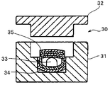
- FIG. 12 shows a state in the middle of manufacturing a molded product having a hollow portion which is one form of a closed cross section by the molding die 30. That is, a sheet-like lower fiber reinforced thermoplastic resin material (hereinafter referred to as a lower FRTP) 34 that has been preheated and is in a molten state is placed on the lower mold 31 of the molding die 30. Since the lower FRTP 34 is in a molten state, the lower FRTP 34 hangs down and sinks into the recess of the lower mold 31 by its own weight.
- a sheet-like lower fiber reinforced thermoplastic resin material hereinafter referred to as a lower FRTP
- the core 33 in which the powder particle group 33a is wrapped with the packaging material 33b and solidified into a predetermined shape by vacuum packing, is placed in the recess of the lower FRTP 34.
- a new sheet-like upper fiber reinforced thermoplastic resin material (hereinafter referred to as upper FRTP) 35 that is heated and melted is placed on the upper part of the lower FRTP 34 on which the core 33 is placed.
- upper FRTP new sheet-like upper fiber reinforced thermoplastic resin material
- the upper mold 32 of the molding die 30 is lowered and the lower FRTP 34 and the upper FRTP 35 are heated and cured between the lower mold 31 and the lower FRTP 34 in a state where the core 33 is housed inside.
- the upper FRTP 35 is formed integrally.
- a small hole is formed in the semi-molded product to communicate with the inside of the core 33.
- the packaging material 33b wrapping the powder particle group 33a is made of a material excellent in peelability with respect to the molded product, the packaging material 33b can also be removed leaving the hollow portion of the molded product. it can.
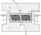
- FIG. 15 shows a state in which the core 43 molded by blow molding is set between the molding dies 41a and 41b for forming the outer layer.
- the molding dies 41a and 41b are configured to accommodate the core 43.
- the molding dies 41a and 41b are clamped, the molding dies 41a and 41b are formed.
- a cavity serving as a hollow portion for filling the molten resin is formed between the mating surfaces 42 a and 42 b and the core 43.
- the molten resin 45 plasticized by the extruder 44 is supplied into the cavity.
- a product having a hollow portion in which the molten resin is integrated with the core 43 can be molded into a desired shape.
- the core 43 may be deformed.
- the core 43 may be similarly deformed because the rigidity is insufficient in the flat portion.
- the invention described in Patent Document 2 adopts a configuration that can increase the internal pressure of the core 43.
- a pressurizing unit 46 communicating with the inside of the core 43 is provided, and by introducing a pressurized gas or liquid into the core 43 from the pressurizing unit 46, The internal pressure is increased to prevent deformation.
- FIG. 16 corresponds to the drawing given in Patent Document 3.
- a mold assembly 57 in which a fiber reinforced plastic material (composite layup) is disposed between at least one separated mold part 57a, 57b forming a mold cavity of the fiber reinforced plastic molded body.
- a pair of elastically deformable chamber walls 55 and 55 fixedly opposed to the first and second pressure chambers 51 and 52.
- a fluid raised to a predetermined temperature and pressure is circulated between the first and second pressure chambers 51 and 52.
- the pair of mold parts 57a and 57b correspond to a so-called male mold and female mold in normal molding.
- the mold assembly 57 is heated and pressurized by a fluid circulating at an elevated temperature and pressure through the chamber walls 55 and 55 of the first and second pressure chambers 51 and 52, respectively. During the heating and pressurization, the pressure chambers 51 and 52 maintain the state in which the elastically deformable chamber walls 55 and 55 are disposed, and the fiber reinforced plastic material is compressed through the mold parts 57a and 57b. And cured to form a fiber reinforced plastic structure.
- the upper die 32 is lowered with the core 33 sandwiched between the lower FRTP 34 and the upper FRTP 35, and the lower FRTP 34 and the upper FRTP 35 are interposed between the lower die 31 and the upper die 32. Apply pressure to.
- the core 33 is placed in the recess formed in the lower FRTP 34 by sinking into the recess of the lower mold 31, or when the upper FRTP 35 is placed over the core 33, the recess of the lower mold 31 is A gap is generated between the corner and the lower FRTP 34 and between the core 33, the lower FRTP 34, and the upper FRTP 35.
- the lower FRTP 34 and the upper FRTP 35 cannot be sufficiently supported from the inside by the core 33.
- the outer surface shape of the lower FRTP 34 is changed in the concave part of the lower mold 31. It cannot be formed in a shape along the shape of the corner, and is formed into a shape that is wrinkled on the outer surface or buckled in the vertical direction. Or the length dimension in a vertical part will be shape
- the lower FRTP 34 and the upper FRTP 35 are made of a long fiber reinforced resin material using long fibers, between the core 33 and the lower FRTP 34 and the upper FRTP 35, or between the upper mold 32 and the lower mold 31 and the lower FRTP 34.
- the pressure molding is performed with a gap between the upper FRTP 35 and the upper FRTP 35, the fiber orientation of the long fibers is disturbed to bend, resulting in a decrease in strength as a fiber reinforced plastic and a deterioration in appearance of the molded product. It will be.
- FIGS. 13 and 14 schematically showing the configuration of the first conventional example. 13 and 14, the vertical portion described above is indicated by reference numeral 37. Then, an annular prepreg 36 having a core 33 disposed therein is housed in a recess formed in the lower mold 31, and the upper mold 32 is lowered toward the lower mold 31. 14 shows a configuration in which a reinforcing rib 39 is provided at the center of the prepreg 36 in the configuration of the prepreg 36 shown in FIG. 13, but the other configurations are the same as those in FIG. Yes.
- a semi-molded product can be manufactured by sandwiching a prepreg 36 between an upper mold 32 and a lower mold 31 and applying heat and pressure. Then, a hole is formed in the finished semi-molded product, and the powder particles constituting the core 33 are discharged out of the hole formed in the semi-molded product, whereby a hollow molded product is completed.
- the outer surface of the core 33 is formed in a case where a semi-molded product is shaped into a shape having a corner.
- a gap is likely to occur between the inner peripheral surface of the prepreg 36.
- the same applies to the corners of the molding surface and the prepreg 36. It becomes easy to produce the space
- the core 33 moves on both sides of the rib 39 when the prepreg 36 is pressurized with the upper mold 32 and the lower mold 31. Therefore, it will be deformed into a more curved shape. And when it will be in a deformation
- the preform accuracy of the prepreg 36 is improved so that no gap is formed between the prepreg 36 and the core 33, It is necessary to form the core 33 in a desired shape.
- the amount of powder particles constituting the core 33 is accurately measured and configured, the shape is also formed in a desired shape, the prepreg 36 is brought into close contact with the core 33, and the outer shape of the prepreg 36 is further changed. Aligning the inner shape of the molding die with the powder particles that are not completely fixed or the uncured prepreg is unstable, requiring a lot of labor and a long time. become.
- the internal pressure of the core 43 and the chamber walls 55 and 55 can be increased by introducing a pressurized gas or liquid.
- a pressurized gas or liquid the pressure at an arbitrary point has a physical property that the same pressure works in all directions. For this reason, when a part of the gas or liquid pressurized to increase the internal pressure leaks from the core 43 or the chamber walls 55 and 55, the leaked gas or liquid becomes a high-speed and high-pressure jet flow.
- the molding dies 41a and 41b and the pressure chambers 51 and 52 are ejected to the outside in a high temperature state. In this case, in particular, when the liquid is ejected, it may cause a large damage around the molding die and the pressure chamber, and may impair the safety of the operator. Therefore, equipment with sufficient safety measures is required.
- the conventional fiber reinforced plastic molding method and molding apparatus having a closed cross section or an open cross section represented by the inventions described in Patent Documents 1 to 3 differ in heating and pressing methods, but both are male and female.
- a pair of molds pressure chamber
- one or both molds are moved in the pressurizing direction to heat a molding material such as a prepreg or layup material interposed between the pair of molds. Pressure.
- a hydraulic cylinder that can withstand a required internal pressure is used for opening and closing operations of the upper dies 32 and 41b, which are movable, for example.
- the expansion / contraction distance is controlled, and an interval between the upper mold and the lower mold during molding is kept constant.
- it can withstand the increase of the pressing force by the prepreg against the inner surface of the upper mold and maintain the position of the upper mold constant, that is, the distance between the upper mold and the lower mold. It becomes difficult to keep the constant.
- a predetermined dimension cannot be obtained in the molded product as a product, and the dimensional variation is large, leading to a decrease in yield.
- the manufacturing cost of the mold itself used for such molding is extremely high, and the mold must be changed every time the shape of the molded product is changed, which greatly affects the molding cost.
- excellent appearance accuracy is required on the outer surface side, but not so much appearance accuracy is often required on the inner surface side.
- the present invention solves the above-mentioned conventional problems and, when molding a molded product having a closed cross section or an open cross section by a molding die, for a prepreg (layup material) without using gas or liquid.
- the pressure can be increased uniformly, and even if pressure is applied to the core or when a normal molding die is used, a part of the medium constituting the core is the molding metal. It is possible to prevent leakage from the mold, and the normal mold is used as the mold that requires a cavity with excellent appearance accuracy, and the mold that allows a slight decrease in appearance accuracy is allowed.
- An object of the present invention is to provide a method for molding a fiber reinforced plastic, which can be molded using a mold having a high degree of freedom of change that can be shared.
- the first basic configuration of the fiber-reinforced plastic molding method of the present invention includes a particle group including a plurality of particles contained in a flexible bag to form a core having a desired shape, and includes a resin and a fiber. Disposing a prepreg around the core; disposing the core and the prepreg disposed around the core between an upper mold and a lower mold of the molding mold; and There is a method for molding a fiber reinforced plastic which includes clamping and compression molding.
- the upper mold is moved upward by moving the mold interval holding means arranged on the left and right side portions of the upper mold by a predetermined amount in a direction approaching each other.
- the left and right side surfaces of the upper mold and the contact surface of the mold interval holding means can be formed in a wedge-shaped sliding surface.
- the particle size of the particles contained in the flexible bag is not uniform.
- a portion where a part of the outer peripheral surface of the core is pressed is a discharge hole forming site for discharging the particle group from the molded product.
- the method includes inserting a rod into the molding die and pressing a part of the outer surface of the core, wherein the rod is preferably a piston rod, Later, the particle group may be discharged to the outside of the molded article through the insertion position of the rod.
- the particle group accommodated in the flexible bag body is a highly rigid particle, and the particle group includes a first particle group (a) and a second particle group (b) having different particle diameters,
- the ratio Da / Db between the diameter Da of the first particle group (a) and the diameter Db of the second particle group (b) is preferably 1.1 or more and 2.0 or less.
- the ratio of the total amount of the second particle group (b) to the total amount of the particle group accommodated in the flexible bag is preferably in the range of 20 to 60% by mass, and more preferably, the upper mold and Hold the mold space holding means so that the space between the lower molds does not widen, and press the part of the outer surface of the core with the pressing means that protrudes and protrudes toward the cavity between the upper mold and the lower mold. It is good to include improving the adhesiveness between the said prepreg, the said metal mold
- the particle group is preferably composed of high-rigidity particles having a diameter of 0.1 mm to 10 mm, and particularly preferably composed of high-rigidity particles having a diameter of 0.5 mm to 2 mm.
- the flexural modulus of the highly rigid particles is preferably 50000 MPa or more, and ceramic particles are preferably used for the highly rigid particles.
- a part of the outer surface of the core is held by a mold interval holding means so that the distance between the upper mold and the lower mold is not widened, and has a pressing means that protrudes and protrudes toward the cavity between the upper mold and the lower mold. It is desirable to increase the adhesiveness between the prepreg, the mold and the core by pressing and deforming by increasing the internal pressure in the core and by pressing deformation of the core.
- the fiber-reinforced plastic molding method of the present invention having the second basic configuration allows a one-side molding die having a one-side cavity for molding one-side surface of a molded product, and a particle group including a plurality of rigid particles.
- a prepreg containing a resin and a fiber is interposed between a deformation mold of a desired shape housed in a flexible bag body, a pressing force is applied to the one-side molding mold, and the one-side molding mold and the deformation mold Pressing the prepreg with a predetermined pressing force, and forming the one-side surface of the prepreg by the one-side molding die at the time of pressing, and at the same time depending on the flow of the particle group inside the deformation mold, the one-side Deforming the deformable mold following the shape of the cavity, and molding the opposite surface of the prepreg.
- the particle group in the deformation mold is preheated prior to molding.
- the particle group is preferably made of metal particles having a diameter of ⁇ 0.1 mm to ⁇ 10 mm.
- this fiber-reinforced plastic molding method is efficiently carried out by a molding apparatus described below. That is, the basic configuration of the fiber-reinforced plastic molding apparatus is the above-mentioned one-side molding die, Arranged between the above-mentioned deformation mold, a floor surface section that accommodates and mounts the deformation mold, an open surface section that is disposed opposite to the floor surface section at a predetermined interval, and the floor surface section and the open surface section.
- a housing having a side wall portion, and a first pressing means for pressing the one-side molding die toward the deformation die with a required pressing force
- the one-side molding die comprising a mold body and the A fiber-reinforced plastic molding apparatus, comprising: a tightly fitting portion that is slidably fitted to an open surface portion of a housing, and having the one-side cavity on a molding surface that faces the floor surface portion of the tightly fitting portion. is there.
- the granule is made of metal particles having a diameter of ⁇ 0.1 mm to ⁇ 10 mm, and the housing advances and retreats toward the deformation mold accommodated therein, and the deformation mold is locally pressed and deformed. It is preferable to have a 2nd press means.
- a core having a desired shape is used by accommodating a group of particles including a plurality of particles in a flexible bag.
- a depression is formed on the outer surface of the core by pressing a part of the outer surface of the core through the prepreg or not through the prepreg during the compression molding by the molding die.
- the internal pressure is forcibly increased.
- slip is generated between particles constituting the core, and the core is deformed.
- particles having fluidity are used as the particle group constituting the core, the outer surface of the core is pressed to form a depression on the outer surface to increase the inner pressure of the core.
- the moving particles move, and the fluidity and pressure transferability of the particles in the core are improved.
- the particle group presses the outer surface of the core, thereby forming a depression on the outer surface of the core to increase the internal pressure of the core and moving the particles constituting the particle group. In combination with increasing the pressure, a molded product excellent in shape and dimensional accuracy can be obtained.
- the gap can be reliably filled by the deformation of the core.
- the prepreg can be moved in the direction of filling the gap by the deformation of the core. Can be filled.
- the gap formed between the prepreg and the core due to the deformation of the core is crushed by the high internal pressure by the core, or the air that formed the gap passes through the prepreg and is released from the molding die to the atmosphere. Will be.
- the passage formed when the air passes through the prepreg is automatically blocked by the molten prepreg after the passage of air.
- the core is configured by accommodating a large number of particles in a flexible bag. For this reason, even if the core is deformed by pressing the outer surface of the core to form a depression on the outer surface, the internal pressure in the core is usually as when using liquid or gas, There is no uniform pressure at all sites. That is, even if pressure is applied to the particle group, a pressure smaller than the pressure at the site where the pressure is applied is generated at the other site. Here, when the applied pressure exceeds a certain value, slip occurs between the particles constituting the particle group.
- the portion on the outer surface side of the core away from this portion The pressure rise at is lower than the internal pressure at the site where the depression is formed.
- the pressure transferability in the core and the fluidity of the particle group are affected by the roughness of the particle surface, the particle diameter, and the particle rigidity constituting the particle group.
- the particles constituting the particle group are packed most densely in the core, and the fluidity of the particles constituting the particle group is hindered. , Pressure transmission is impaired.
- the particle size distribution in the core and the distribution of the surface roughness of the particle are taken into consideration, or a particle group combining high-rigidity particles and particles of thermoplastic resin having different rigidity, for example, By using, the fluidity and pressure transferability of the particles constituting the particle group in the core are improved.
- the core is deformed by the sliding of the constituent particles of the particle group even in the portion in the core away from the portion where the depression is formed by the pressing.
- the prepreg can be pressed along the molding surface of the molding die. For example, the pressure between the core part supporting the vertical part as described above and the prepreg is increased. Can do. Thereby, at the time of pressurization with the upper mold and the lower mold, the bending deformation in the vertical portion as described above can be surely prevented.
- high-rigidity particles having fluidity alone or particles composed of the high-rigidity particles and resin particles as the particle group accommodated in the core.
- the high-rigidity particles ceramics such as alumina and zirconia, glass, hard heat-resistant resin, metal, foundry sand and the like having high rigidity with a flexural modulus of 50000 MPa or more can be used.
- zirconia or quartz made of ceramic since these materials have low thermal conductivity, they are suitable materials for the particles constituting the core 4 particle group.
- polyolefins such as polypropylene and polyethylene
- various thermoplastic resins such as acrylic, nylon, and Teflon (registered trademark)
- various elastomers such as silicone
- a thermoplastic resin having a flexural modulus of 10 to 3000 MPa is used, the fluidity and transferability of the rigid particles are improved, so that it is a suitable material for the core particle group.
- the inner surface of the core is increased by pressing the outer surface of the core and forming a recess in the outer surface.
- the resin particles are elastically deformed, slip between the particles constituting the particle group occurs, and the high-rigidity particles move to improve the fluidity and pressure transferability of the particle group in the core.
- the resin particles press the partial outer surface of the core to form depressions on the outer surface to increase the internal pressure of the core and move the highly rigid particles, and then the particles constituting the particle group move.
- each particle constituting the particle group moves while sliding in the front-rear and left-right directions, but the flexible bag containing each particle group is made of a material that can be extended. It is configured. Therefore, deformation of the outer shape of the core accompanying the movement of the particles constituting each particle group can be allowed by the flexible bag that can be extended.
- the flexible body of the core resists these pressures.
- the particle group may break the bag. However, if the gap between the molding dies is smaller than the diameter of the particles, no leakage will occur from the molding dies unless the particles are crushed.
- a rod that can be projected and retracted in the molding surface of the molding die As a means for pressing a part of the outer surface of the core, it is preferable to use a rod that can be projected and retracted in the molding surface of the molding die.
- a piston rod can be used as the rod, and such pressing means can be installed at a plurality of sites.
- a part of the outer surface of the core when the outer surface of the core is pressed, a part of the outer surface of the core can be pressed through the prepreg or without the prepreg.
- a substantially planar portion is pressed through the prepreg, a recess is formed in the prepreg.
- the prepreg becomes flat.
- a discharge hole for discharging the particle group constituting the core from the molded product can be provided in the depressed portion or the flat portion which is the pressed portion, or in addition to the pressed portion.
- a hole having a shape corresponding to the cross-sectional shape of the pressing portion such as a rod is formed in the prepreg, and the rod is formed after the semi-molded product is formed. Press directly on the core.
- the flexible bag can be broken from the hole position of the semi-molded product to discharge the particles, and the flexible bag can be taken out.
- the flexible bag body can be removed from the semi-molded product by performing a release treatment such as applying a release agent or forming a double package so that the flexible bag body is in contact with the particles.
- the mold interval holding means is provided so that the interval between the upper mold and the lower mold is not widened when the mold is clamped or pressure-molded. It is good to hold.
- the mold interval holding means is arranged on the left and right side portions of the upper mold, and the mold interval holding means arranged on the left and right side portions of the upper mold is moved by a predetermined amount in a direction approaching each other. Including fully restricting the upward movement of the upper mold. It is preferable that the left and right side surfaces of the upper mold and the contact surface of the mold interval holding means are relatively wedge-shaped sliding surfaces.
- the pair of left and right mold interval holding means is set at a predetermined distance in the approach direction. When it is moved horizontally, it will abut against the upper mold in the middle, preventing the upper mold from moving further upward, and maintaining the specified distance between the upper mold and the lower mold in the vertical part described above. Is done. In this way, the clamping position of the molding die is fixed, and an increase in pressing force between the outer peripheral surface of the core and the inner surface of the prepreg is ensured.
- the prepreg can be formed to a desired thickness.
- the pressure rise due to expansion of the core becomes more than specified, and the upper mold is moved up against the cylinder.
- the distance between the upper and lower molds is increased, and a product having a height higher than a prescribed dimension is manufactured.
- the mold interval holding means it is preferable to employ a wedge surface.
- the upper end shoulders of the left and right side surfaces of the upper mold are formed on the lower inclined surface facing outward, while the lower end corners of the opposing surfaces of the pair of left and right mold interval holding means are also facing outward. Formed on the lower inclined surface. For example, after moving the mold interval holding means horizontally in the approaching direction, the facing inclined surfaces of the upper mold and the mold interval holding means are in contact with each other, and then the left and right mold interval holding means are further moved in the approaching direction.
- maintenance means will push the inclined surface of an upper mold
- the upper limit movement position of the upper mold is determined, and the upper mold is restricted from moving further upward. Therefore, the upper mold maintains the movement limit position even when the pressing force against the cavity surface of the upper mold received from the core via the prepreg is increased.
- the present invention has the above-described second basic structure, particularly the most characteristic part of the conventional male and female molds, and one of the molds has the same rigid mold (one-side mold) as the conventional one. It is also possible to employ a configuration in which a deformable deformable mold in which a large number of particles having high fluidity are enclosed in a sealed manner is used for the flexible bag body. In this case, a housing for supporting the deformable mold in a deformable manner is prepared.
- the present invention having the second basic configuration will be described with a molding die having a one-side mold as an upper die and a deformation die as a lower die as a representative example.
- the housing can be heated, and the deformable die is placed on the floor surface of the housing.
- the granules contained in the deformable flexible bag may be preheated to 100 ° C. to 200 ° C. together with the bag.
- a prepreg made of a single or laminated fiber assembly and impregnated with a matrix resin is placed on the deformable mold.
- the inner surface of the one-side mold in which the required cavity is formed is directed toward the prepreg, the mold is closely fitted in the opening of the housing, and is pressed and moved with a required load in the direction of pressing the prepreg.
- the surface of the prepreg on one side of the mold is shaped into a predetermined shape under a large pressing force by the cavity surface of the mold.
- the deformable mold disposed on the surface of the prepreg opposite to the one-side mold has the flexible bag body constituting the deformable mold being restrained by the floor surface portion and the side wall portion of the housing. The floor is spread over the entire surface and no further deformation occurs.
- the surface of the deformable mold facing the prepreg receives reaction force from the floor portion or the like, and moves the granules in the bag body while deforming the prepreg, thereby deforming the bag body.
- the deformation at this time is made by the internal particles automatically flowing in a direction that equalizes the internal stress of the prepreg.
- the surface of the prepreg on one side of the mold is subjected to the reaction force of the deformation mold arranged on the opposite side of the mold, and is shaped into the cavity shape of the mold, and the deformation on the opposite side
- the surface on the side in contact with the mold is deformed following the deformation of the entire mold surface of the prepreg, and any gap generated between the deformed mold and the prepreg is filled based on the deformation of the deformed mold.
- a shape corresponding to the uniform stress inside the prepreg generated between the mold and the deformable mold is
- a new one-side mold is first prepared, and the previously used one-side mold is removed from the molding machine and replaced with a new one-side mold.
- the above-described modified type is not required. That is, the deformation mold is used as it is for subsequent molding without replacement. In this way, in the present invention, if only one side of the pair of molds is replaced, a molded product having the next new shape and structure can be molded.
- the manufacturing cost of the mold required for molding can be halved, and the price of the molded product can be greatly reduced.
- the deformable internal particles flow freely by external force (pressing force) on the surface opposite to the die side surface of the prepreg during press molding, the necessary and sufficient pressing force should be applied evenly.
- a part of the deformation mold is applied locally by using, for example, a rod material, which is an auxiliary pressing means, and the internal pressure of the deformation mold is further increased, the surface pressure always acts on the prepreg. Therefore, in the molding of this kind of fiber reinforced plastic products that focus on the fiber direction without affecting the direction of the fibers constituting the prepreg, the production of high quality products is always guaranteed. Is done.
- the fiber-reinforced plastic molding method according to the present invention is to increase the outer peripheral surface area of the core during pressure molding using the molding die, even if the molding die, core, etc. are not described below. If it is the structure which can do, this invention can be applied suitably also to those structures.
- a molding die 15 obtained by preheating a preform obtained by shaping a prepreg 3 including a core 4 into a shape substantially the same as the inner peripheral surface of the molding die 15 at room temperature. It is placed in a recess 1 a formed in the lower mold 1.
- the prepreg 3 can be formed in the form of a sheet obtained by impregnating a fiber such as carbon fiber, glass fiber, aramid fiber, or silicon carbide fiber with an uncured thermosetting resin.
- a fiber such as carbon fiber, glass fiber, aramid fiber, or silicon carbide fiber
- an uncured thermosetting resin such as polymethyl methacrylate, polymethyl methacrylate, polymethyl methacrylate, polymethyl methacrylate, polymethyl methacrylate, polymethyl methacrylate, polymethyl methacrylate, polymethyl methacrylate, polymethyl methacrylate, polymethyl methacrylate, polymethyl methacrylate, polymethyl methacrylate, polymethyl methacrylate, polymethyl methacrylate, polymethyl methacrylate, polymethyl methacrylate, polymethyl methacrylate, polymethyl methacrylate, polymethyl methacrylate, polymethyl methacrylate, polymethyl methacrylate, polymethyl methacrylate, polymethyl methacrylate, polymethyl methacrylate, polymethyl me
- the molten prepreg 3 is cured by pressure molding in the molding die 15 to form a fiber reinforced plastic (FRP) having a desired shape.
- FRP fiber reinforced plastic
- Product can be manufactured.
- the thermoplastic resin is impregnated instead of the thermosetting resin, the preform formed by heating the prepreg 3 in advance is pressure-molded by a molding die and then cooled to obtain an FRP having a desired shape. Molded articles can be manufactured.
- Epoxy resin, urea resin, vinyl ester resin, unsaturated polyester, polyurethane, phenol resin, etc. can be used as the thermosetting resin impregnated into the fiber, and polypropylene, polyethylene, polystyrene, vinyl chloride can be used as the thermoplastic resin. Polyamide resin or the like can be used.
- the core 4 is configured by accommodating a particle group 4a in a flexible bag 4b.
- the high-rigidity particles ceramics such as alumina and zirconia, glass, hard heat-resistant resin, metal, foundry sand and the like having high rigidity with a flexural modulus of 50000 MPa or more can be used.
- a ceramic made of zirconia or quartz since these materials have low thermal conductivity, they are suitable materials for the particles constituting the core 4 particle group 4a.
- a nylon film, a polyethylene film, a fluororesin film, silicon rubber, or the like can be used as the flexible bag 4b used for maintaining the shape of the core 4.
- the particle group 4a of the core 4 uses particles (a) and (b) having a particle size ratio that satisfies the following formula (1). At this time, when the ratio of the total amount of the particles (b) contained in the particle group 4a is in the range of 20 to 60% by mass, the fluidity and pressure transferability of the particle group 4a are improved and a suitable particle group configuration is obtained. . 1.1 ⁇ (Da / Db) ⁇ 2.0 (1) Here, Da is the particle diameter of the particle (a), and Db is the particle diameter of the particle (b).
- the lower mold 1 is provided with a cylinder 5 provided with a piston rod 5a that can be moved into and out of the cavity of the molding die 15.
- the piping for supplying and discharging the working fluid to and from the pressure chamber of the cylinder 5 in order to slide the piston rod 5 a is omitted.
- the upper mold 2 and the lower mold 1 are moved in directions close to each other, complete clamping is performed, and the prepreg 3 placed in the recess 1a of the lower mold 1 can be heat-cured under pressure. .
- the pressure is not high, and the pressure is increased by the piston rod in the next stage. Therefore, a mold opening / closing mechanism is sufficient as the mold clamping machine, and a high-pressure press is not required.
- the prepreg is pressed by the core 4 whose outer surface shape is widened. 3 is deformed and moved to the gap side. And the air which formed this space
- the prepreg 3 moves to the space where the air is pushed out, and is formed into a shape along the corner shape of the molding die 15.
- the molded product formed by heating and pressurizing the prepreg 3 is, for example, a molded product in which the corners are formed at right angles.
- the thickness of the flexible bag 4b is exaggerated and thick in order to make the flexible bag 4b easier to understand.
- the flexible bag 4b is formed in a thin film shape having a thickness of 1 mm or less.
- the configuration for molding a square pipe-shaped molded product is described, but the molded product can be molded into other various and complicated shapes having a closed cross section.
- the shape close to the closed cross section includes a C-shaped cross section.
- a C-shaped cross section in addition to a shape such as a square pipe shape, for example, a C-shaped cross section is also included in the closed section in the present invention.
- a depression 6 is formed on the outer surface of the prepreg 3 by pressing a part of the outer surface of the core 4 with the piston rod 5a.
- the volume of the piston rod 5a that has entered the volume of the particle group 4a is forcibly added as the volume in the core 4.
- the internal pressure in the core 4 can be increased.
- each particle group 4a slides between the particles and moves in the front-rear and left-right directions.
- the flexible bag 4b that accommodates each particle group 4a is made of a material that is easily deformed so that it can be vacuum-packed, the flexible bag 4b moves the particle group 4a. Can be extended without substantially limiting.
- the internal pressure of the core 4 can be increased and slip can occur between the particles constituting the particle group 4a, the outer peripheral surface area of the core 4 can be increased, and as shown in FIG. The gap between the child 4 and the prepreg 3 can be eliminated.
- the expansion of the outer surface shape of the core 4 occurs at a portion where the pressure with the prepreg 3 where a gap is generated is low, so that the thickness of the prepreg 3 is reduced to a predetermined thickness while eliminating the gap. Can be maintained.
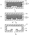
- FIG. 3A shows a state in which the semi-molded product 10 a that has been subjected to pressure molding by the molding die 15 is taken out from the molding die 15.
- a concave portion 6 is formed in a portion of the prepreg 3 pressed by the piston rod 5a.
- FIG. 3B when the discharge hole 6a is opened in the recess 6, the particles (a) and particles (b) of the particle group 4a accommodated in the flexible bag 4b from the hole 6a. In between, air flows in and the coupling
- the particle group 4 in which the bonded state is broken is discharged to the outside from the discharge hole 6a formed in the recess 6 to complete the molded product 10 having the hollow portion 10b as shown in FIG. .
- the flexible bag 4b that has contained the particle group 4a is made of a material that has good peelability with respect to the molded product 10, or if the flexible bag 4b is doubled, the particle group 4a The flexible bag 4b in contact with can also be removed from the semi-molded product 10a.
- the molded product 10 has a desired thickness with no desired bending or wrinkles.
- a product having a surface shape can be produced.
- the internal pressure in the core 4 can be increased by the pressing force applied from the piston rod 5a. For example, a product having a desired wall thickness and a desired outer surface shape can be obtained.
- the fluidity of the particle group 4a of the core 4 was measured by the following method. First, the fluidity of the particle group 4a has a cavity having a thickness of 30 mm, a length of 300 mm, and a width of 100 mm, (1) center of the molded plate, (2) 65 mm from the center to the length direction, and (3) length from the center. Using a mold that can measure the pressure of the outer surface of the core at each position 130 mm in the direction, the mold temperature is 140 ° C., the molding pressure is 1.5 MPa, and a predetermined amount of sample is charged at the center of the mold.
- the fluidity of the particle group 4a obtained in each example is as follows: (1) center, (2) 65mm from the center to the length direction of the mold capable of measuring the pressure on the outer surface of the core 4, (3) The surface pressure peak values measured at three locations 130 mm in the length direction from the center were evaluated according to the following criteria.
- X The range of the pressure peak value of the surface of 3 places is 10% or more, and the internal pressure is not applied uniformly.
- Example 1 As shown in FIG. 1, the total amount of particles (b) contained in the mixture of zirconia particles in a mixture of zirconia particles having a particle size ratio of 1.5 (particle (a): diameter 3 mm, particle (b): diameter 2 mm)) A particle group having a ratio of 20 (mixing ratio of particles (b)) of 20% by mass was accommodated in a bag made of a nylon film to produce a core.
- Carbon fiber reinforced epoxy resin prepreg 3 (Mitsubishi Rayon Co., Ltd., product name: TR3110 391 IMU) is encased in 5 plies and the core is enclosed in a shape substantially the same as the inner peripheral surface shape of the molding die 15 at room temperature. Renovated.
- the preform is placed in the recess 1a formed in the cavity surface of the lower mold 1 of the molding die 15 heated in advance to 140 ° C., the upper mold 2 and the lower mold 1 are completely clamped, and then the piston A part of the outer surface of the core 4 was pressed at 8.0 MPa with the rod 5a. After 10 minutes, the mold was opened and the semi-molded product was taken out.
- a hole for discharge is formed in the recess 6 (FIG. 3 (a)) formed by pressing with the piston rod, and the zirconia particles (particle group 4a) are discharged to the outside through the hole for discharge (FIG. 3 (b)).
- a molded product was obtained (FIG. 3C).
- Example 2 A hollow molded article was obtained in the same manner as in Example 1 except that the mixing ratio of the zirconia particles (b) contained in the particle group 4a of the core 4 shown in Table 1 was set (FIG. 3 (c)).
- Example 1 A hollow molded article was obtained in the same manner as in Example 1 except that the mixing ratio of the zirconia particles (b) contained in the particle group 4a of the core 4 shown in Table 1 was 10% by mass (FIG. 3C). ).
- Example 2 A hollow molded article was obtained in the same manner as in Example 1 except that the zirconia particles having a uniform particle diameter shown in Table 1 were used for the particle group 4a of the core 4 (FIG. 3 (c)).
- zirconia particles are used as the particles constituting the particle group 4a of the core 4, and the ratio of the diameter Da of the first particle group (a) to the diameter Db of the second particle group (b) ( In the production methods according to Examples 1 to 4 in which Da / Db) is 1.5 and the ratio of the total amount of the second particle group (b) to the total amount of the particle group 4a is 20 to 50% by mass, The fluidity and pressure transferability of the group 4a were improved, the dimensional accuracy of the obtained molded product was high, and the appearance free from defects such as wrinkles on the outer surface was excellent.
- zirconia particles are used as the particles constituting the particle group 4a of the core 4, and the ratio (Da / Db) between the diameter Da of the first particle group (a) and the diameter Db of the second particle group (b) is Comparative Example 1 using a particle group in which the ratio of the total amount of the second particle group (b) to the total amount of the particle group 4a is 10% by mass, and zirconia particles having a uniform particle diameter are used.
- the particles constituting the particle group 4a are filled with the highest density, the fluidity of the particles constituting the particle group is hindered, and the pressure transmission property is impaired.
- the molded product thus obtained had a reduced dimensional accuracy, had defects such as wrinkles on the outer surface, and could not obtain a good appearance.
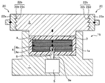
- the upper mold 2 is provided with a mold interval holding means 20 for holding the interval between the upper and lower molds 2 and 1 constant.
- the mold interval holding means 20 has an increase in pressing force due to deformation of the prepreg 3 with respect to the upper mold 2. The configuration that does not lift is adopted.
- the mold interval holding means 20 is formed on the lower inclined surfaces 2a and 2a formed on the upper left and right side upper ends of the upper mold 2 (left and right upper shoulders in FIG. 4).
- a pair of left and right presser members 21a, 21a having wedge surfaces 21b, 21b that are in sliding contact with each other and slidable in a direction (horizontal direction) perpendicular to the moving direction (vertical direction) of the upper mold 2; 21a, 21a is provided with a drive unit (not shown) that moves in the horizontal direction to drive in the approaching and separating directions.
- the shape of the opposing wedge surfaces 21b, 21b of the pair of left and right pressing members 21a, 21a is such that the distance between the opposing wedge surfaces 21b, 21b expands downward. Has been.
- the pair of presser members 21a and 21a approach the lower inclined surface formed at the upper ends of the left and right side surfaces of the upper mold 2.
- the wedge action by the lower inclined surfaces 21a and 21a and the wedge surfaces 21b and 21b formed at the upper ends of the left and right side surfaces of the upper mold 2 works.
- the separation distance between the upper and lower molding surfaces of the upper and lower molds 2 and 1 is determined by the movement stop position of the pressing member 21a in the left and right direction, and further movement of the upper mold 2 upward is prevented.
- the interval between the upper die 2 and the lower die 1 is determined by the stop position of the pressing member 21a, the interval between the upper die 2 and the lower die 1 is arbitrarily adjusted by adjusting the stop position. can do.
- this stop position is determined, even if a strong force is applied to the upper mold 2 from below, the upper mold 2 remains in an immobile state and the immovable position is reliably maintained, so that a molded product with high dimensional accuracy is obtained. Can be obtained.
- the effect of pressing by the piston rod 5a will be described under the following assumptions.
- the pressing surface that presses the prepreg 3 with the upper mold 2 shown in FIG. 4 has a rectangular shape, the pressing surface has a width W of 100 mm, and a depth of 300 mm.
- the diameter of the piston rod 5a is assumed to be ⁇ 38 mm, and the cylinder diameter of the cylinder 5 is assumed to be ⁇ 130 mm.
- type 2 shall be (phi) 252mm.
- the press pressure in the said press apparatus is 50 kg / cm ⁇ 2 > which is twice 25 kg / cm ⁇ 2 >
- type 2 is when the press pressure mentioned above is 25 kg / cm ⁇ 2 >.
- the small press device and the cylinder 5 that presses the core 4 are used, as in the case where the large press device is used. It is possible to eliminate gaps generated between the molding die 15 and the prepreg 3 and between the prepreg 3 and the core 4.
- the mold interval holding means 20 is provided in the upper die 2 in order to keep the vertical interval between the upper and lower die 2 and 1 constant as described above.
- the pair of left and right holding members 21a, 21a of the mold interval holding means 20 is moved horizontally so as to approach the lower inclined surfaces 2a, 2a formed at the upper end portions of the left and right side surfaces of the upper die 2, the upper die
- the wedge action by the lower inclined surfaces 2a, 2a and the wedge surfaces 21b, 21b formed at the upper end portions of the left and right side surfaces of the two works.
- the separation distance between the upper and lower molding surfaces of the upper and lower molds 2 and 1 is determined by the movement stop position of the pressing member 21a in the left and right direction, and further movement of the upper mold 2 upward is prevented.
- the configuration in which the piston rod 5a is provided in the lower mold 1 has been described, but a configuration in which the piston rod 5a is provided in the upper mold 2 can be employed.
- the piston rod 5a is provided on the upper mold 2 side, and the lower mold 1 is placed on a base or the like to restrict movement.
- the upper mold 2 is movable up and down as usual. Therefore, as the configuration of the mold interval holding means 20 for preventing the upper mold 2 from lifting when the core 4 is pressed by the piston rod 5a, the same configuration as that in FIG. 1 can be adopted.
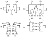
- Modification 2 Modification 2 according to the present invention will be described with reference to FIGS. 5 and 7B.
- first modification an example in which a pair of presser members 21a and 21a having wedge surfaces 21b and 21b that are simply inclined is used as a presser member of the mold interval holding means 20, but in the second modification, a mold is used.
- a pair of pressing members 22a and 22a each having saw-toothed wedge surfaces 22b and 22b are used for the mold interval holding means 20, respectively.
- sawtooth surfaces are respectively formed at both ends of the upper die 2.
- the other configuration has the same configuration as that of the first embodiment, and the same reference numerals as those used in the first embodiment are used for the same components, and the description of the members is omitted.
- the sawtooth wedge surfaces 22b, 22b formed on the pair of pressing members 22a, 22a are horizontal surfaces 22c, 22c formed in the horizontal direction and the base ends of the horizontal surfaces 22c, 22c.
- the shape including the lower inclined surfaces 22d and 22d that continuously incline downward is repeated.
- the mold interval holding means 20 is operated.
- the pair of pressing members 22a and 22a are brought close to each other, the horizontal surface of the saw-toothed surface formed on the upper mold 2 and the horizontal surfaces 22c and 22c of the pressing members 22a and 22a are brought into surface contact. This can reliably prevent the upper mold 2 from moving upward.
- the piston rod 5a is operated from this state, and the core 4 can be forcibly pressed and deformed by the piston rod 5a. That is, the core 4 can be deformed by pressing with the piston rod 5 a, and a gap can be eliminated between the core 4 and the prepreg 3.
- the prepreg 3 can be pressure-molded so that a high-quality molded product having a desired thickness and a desired outer peripheral surface shape can be manufactured.
- a pair of presser members 22a and 22a each having saw-toothed wedge surfaces 22b and 22b are used for the mold interval holding means 20, respectively. Molding was performed in the same manner. The mold is opened, the molded product is taken out, a hole for discharging is formed in the recessed portion 6 (FIG. 3 (a)) formed by pressing the piston rod, and the particle group 4a is discharged from the hole for discharging (FIG. 3). (B)), a hollow molded product was obtained (FIG. 3 (c)). This molded product had high dimensional accuracy and was excellent in appearance without defects such as wrinkles on the outer surface.
- Modification 3 The configuration of Modification 3 according to the present invention will be described with reference to FIGS. 6 and 7C.
- the configuration using the pair of pressing members 21a and 21a having the wedge surfaces 21b that are simply inclined as the mold interval holding means 20 has been described, but in the third modification, the mold interval holding means 20 is used.
- a pair of pressing members 23a and 23a having wedge portions 23b and 23b each having an upper inclined surface formed on a lower surface extending in the horizontal direction and vertical portions 23f and 23f extending vertically downward from an outer end portion thereof,
- the left and right ends of the upper mold 2 are formed in a surface shape in which the opposing surfaces of the pressing members 23a and 23a are in close contact with each other when the pair of pressing members 23a and 23a are brought into contact with the both ends.
- the upper cavity surface of the upper mold 2 is not a mere flat surface but a protruding portion 8 is formed.
- the other configuration is the same as that of the first modification, and the same reference numerals as those used in the first embodiment are used for the same components, and the description of the members is omitted.
- each of the wedge portions 23b and 23b formed on the pair of left and right pressing members 23a and 23a has an upper inclined surface 23c extending in the lateral direction toward the upper mold 2 and the upper inclined surface. It consists of a wedge portion 23b having a shape with vertical surfaces 23d and 23e extending vertically from both edge sides of the surface 23c, and a vertical portion 23f. Then, as shown in FIG. 6, the upper mold 2 is reliably moved upward by the surface contact between the inclined surfaces of the left and right ends of the upper mold 2 and the upper inclined surfaces 23c, 23c of the pressing members 23a, 23a. Can be blocked. Further, by sliding the pair of pressing members 23a, 23a in the direction approaching / separating each other, the upper die 2 is moved in the approaching / separating direction to the lower die 1, and the upper die 2 is moved to the lower die 1. The interval can be adjusted.
- the piston rod 5a is actuated to forcibly deform the core 4 between the protruding portion 8 and the piston rod 5a.
- the core 4 can be deformed, and the gap between the core 4 and the prepreg 3 can be eliminated.
- a high-quality hollow reinforced fiber plastic molded product having a desired wall thickness and a desired outer peripheral surface shape can be manufactured.
- the upper cavity surface of the upper mold 2 is not a mere plane, but has a protruding portion 8.
- the pair of presser members 23a and 23a having wedge portions 23b and 23b each having an upper inclined surface formed thereon and vertical portions 23f and 23f extending vertically downward from the outer end portions thereof, molding is performed in the same manner as in the first embodiment. It was. The mold was opened, the molded product was taken out, a discharge hole was formed in the recessed portion 6 formed by pressing the piston rod, and the particle group 4a was discharged outside through the discharge hole to obtain a hollow molded product.
- This molded product had high dimensional accuracy and was excellent in appearance without defects such as wrinkles on the outer surface.
- FIG. 7 Various configurations as shown in FIG. 7 can be adopted as the configuration of the pair of pressing members in the mold interval holding means 20.
- FIGS. 7A to 7C have been described as the first to third modifications
- the modification examples of the pressing member of the second modification shown in FIGS. 2 and 7B are as follows. This will be described with reference to FIG.
- the wedge surfaces 24b and 24b are formed in a sawtooth shape, but the single teeth as shown in FIG. This is not a sawtooth shape but a double-toothed sawtooth shape.
- wedge surfaces corresponding to the shapes of the wedge surfaces 24b and 24b are formed on the left and right ends of the upper mold 2.
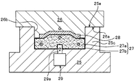
- reference numeral 25 denotes a housing
- reference numeral 26 denotes a one-side mold which is one of a pair of molds
- reference numeral 27 denotes a deformable deformation which is the other mold which is the most characteristic of the present invention
- Reference numeral 28 denotes a prepreg which is a molding material.
- the housing 25 is made of cast iron and has a box shape having a floor portion 25a and a side wall portion 25c erected along the peripheral edge portion of the floor portion 25a. 25d is configured.
- the one-side mold 26 is made of the same material as a normal molding mold, and has a cavity 26a for molding one side of a fiber-reinforced plastic molded product on its molding surface.
- the deformable mold 27 has a configuration in which the particles 27a are housed in a sealed state in a bag 27b made of a flexible material, and can be freely deformed by an external force.
- the particles 27a ceramic balls such as alumina balls and zirconia balls, and metal balls such as chrome steel balls, carbon steel balls, and stainless steel balls are used. Of these, alumina spheres and metal spheres are preferred because of their excellent thermal conductivity, and carbon steel balls are particularly preferred.
- the dimension is preferably ⁇ 0.1 mm to ⁇ 10 mm, and more preferably ⁇ 0.5 mm to ⁇ 2 mm, in order to ensure the deformability in the micro region of the deformable mold 27.
- a film or sheet made of nylon, polyethylene, fluororesin, silicon rubber, or the like is preferably used for the bag body 27b that accommodates the particles 27a.
- the prepreg 28 is obtained by impregnating a fiber aggregate such as a sheet-like carbon fiber, glass fiber, aramid fiber, or silicon carbide fiber with an uncured thermosetting resin or thermoplastic resin as a matrix resin.
- a fiber aggregate such as a sheet-like carbon fiber, glass fiber, aramid fiber, or silicon carbide fiber
- the second sheet-like prepreg 28b having a small area is laminated and integrated at the center of the lower surface of the first sheet-like prepreg 28a having a large area as the prepreg 28.
- a prepreg is used, and the prepreg 28 is placed on the center of the upper surface of the deformable mold 27.
- the fiber assembly preferably imparts directionality to the fibers.
- a sheet-like material in which the fibers are aligned in one direction in parallel a sheet-like material in which the fibers are aligned in one direction at a required angle
- a large number of fiber bundles as warp yarns and crossing the warp yarns at a required interval.
- fabrics such as a woven fabric and a bi-directional fabric obtained by using a large number of fiber bundles for warps and wefts.
- the fiber bundle is composed of a large number of filament yarns.
- the prepreg 28 When a thermosetting resin is used as the matrix resin, the prepreg 28 that is in a molten state is heated and pressed in the housing 25 to be cured by press molding in the housing 25 by heating the molding die. A molded product of fiber-reinforced plastic having a shape can be produced.
- the thermoplastic resin is impregnated instead of the thermosetting resin, the preform in which the prepreg 28 is preliminarily shaped as necessary is preheated and placed on the deformation mold 27, and the one-side mold 26 is The fiber-reinforced plastic molded article having a desired shape can be manufactured by lowering, pressurizing and cooling.
- Epoxy resin, urea resin, vinyl ester resin, unsaturated polyester, polyurethane, phenol resin, etc. can be used as the thermosetting resin impregnated into the fiber, and polypropylene, polyethylene, polystyrene, vinyl chloride can be used as the thermoplastic resin. Polyamide resin or the like can be used.
- the one-side mold 26 is closely fitted in the opening 25d of the housing 25, and then the housing floor surface 25a. Move while applying the required weight. By this movement, the pressing force by the one-side mold 26 against the prepreg 28 placed on the deformation mold 27 gradually increases. Due to this increasing pressing force, the upper surface of the prepreg 28 is shaped into a shape along the cavity surface 26 a of the one-side mold 26. Moreover, at this time, the deformable die 27 on which the prepreg 28 is placed also receives the same pressing force, and the deformable die 27 itself is deformed while deforming the placement surface of the prepreg 28.
- the deformation of the deformation mold 27 is caused by the pressing force of the one-side mold 26 and the reaction force received from the floor surface of the housing 25, toward the gap space formed inside the one-side mold 26 and the housing 25. Is made to flow.
- the deformation die 27 is deformed by utilizing the flow of the granular material 27a, and finally the internal stress of the prepreg 28 is equalized, and the shape of the prepreg 28 on the side opposite to the mold becomes a shape corresponding to the stress. .
- FIG. 11 shows another exemplary embodiment of the present invention.
- the floor surface portion 25a of the housing 25 is provided with a piston rod 29a corresponding to a part of the auxiliary pressing means of the present invention that can be moved in and out toward the deformable mold 27 placed on the housing 25.
- a cylinder 29 is provided.
- the same reference numerals and the same names are used for substantially the same constituent members as those of the above-described embodiment shown in FIGS.
- the piping for supplying and discharging the working fluid to and from the pressure chamber of the cylinder 29 for sliding the piston rod 29 a is not shown.
- the piston rod 29 a operates the cylinder 29 to deform the deformation mold 27.
- An equal pressing force is applied to the prepreg 28 while increasing the internal pressure of the prepreg 28 to increase the volume of the deformable mold.
- the cylinder 29 is By actuating, the piston rod 29a is extended toward the deformation die 27, the deformation die 27 is locally pressed and deformed, the internal pressure is increased, and the granule 27a is directed toward the gap space while deforming the deformation die 27.
- the air constituting the gap space is crushed by the internal pressure of the deformation mold 27 and the pressure of the granules 27a, or is released into the atmosphere through the prepreg 28 through a slight gap between the housing 25 and the one-side mold 26. .
- the air passage formed when air passes through the prepreg 25 is naturally blocked by the molten prepreg 28 after the air has passed.
- the deformation mold 27 extends while being deformed into the gap space where the air is pushed out, and becomes a shape along the corner shape of the one-side mold 26.
- the prepreg 28 follows this.
- the molded product formed by heating and pressurizing the prepreg 28 is formed so that the outer surface side is shaped according to the shape of the cavity 26a of the one-side mold 26, and the inner surface on the opposite side is formed based on the shape of the cavity 26a.
- the shape follows the deformation of 28.
- the particles 27a move in all directions due to slippage between the particles.
- the flexible bag 27b packaging each particle 27a is made of a material that easily deforms, the bag 27b extends without substantially restricting the movement of each particle 27a. be able to.
- the outer peripheral surface area of the deformable mold 27 can be increased. As shown in FIG. The gap between the cavity 26a and the prepreg 28 can be eliminated. Moreover, the expansion of the outer peripheral surface shape of the deformable mold 27 occurs at a portion where the pressure between the one-side mold 26 and the prepreg 24 where the gap space is generated is low, so that the gap of the prepreg 28 is eliminated while eliminating the gap space. Equalize the wall thickness. Thus, the prepreg 28 having a predetermined thickness and having a desired outer peripheral surface shape can be pressure-molded.
Abstract
Description
なお、図14では、図13に示すプリプレグ36の構成において、プリプレグ36の中央部に補強用のリブ39を設けた構成を示しているが、他の構成は図6と同様の構成になっている。
すなわち、繊維強化プラスチックの成形装置の基本構成は、上述の片側成形金型と、
上記変形型と、該変形型を収容載置する床面部、その床面部と対向して所要の間隔をおいて配される開放面部、及び前記床面部と前記開放面部との間に配される側壁部を有するハウジングと、前記片側成形金型を所要の押圧力をもって前記変形型に向けて押圧する第1の押圧手段と、を備えており、前記片側成形金型が、金型本体と前記ハウジングの開放面部に摺接可能に密嵌する密嵌部とを有し、該密嵌部の前記床面部に対向する成形面に上記片側キャビティを有してなる、繊維強化プラスチックの成形装置にある。
高剛性粒子としては、曲げ弾性率が50000MPa以上の高い剛性をもつ、アルミナ、ジルコニア等のセラミック、ガラス、硬質耐熱樹脂、金属、鋳物砂等を用いることができる。特に、セラミックからなる、ジルコニア、石英を用いた場合には、これらの物質は、熱伝導率が低いので、中子4の粒子群を構成する粒子としては好適な材料となる。
高剛性粒子としては、曲げ弾性率が50000MPa以上の高い剛性をもつ、アルミナ、ジルコニア等のセラミック、ガラス、硬質耐熱樹脂、金属、鋳物砂等を用いることができる。特に、ジルコニア、石英からなるセラミックを用いた場合には、これらの物質は、熱伝導率が低いので、中子4の粒子群4aを構成する粒子としては好適な材料となる。
1.1≦(Da/Db)≦2.0・・・(1)
ここで、Daは粒子(a)の粒子の直径、Dbは粒子(b)の粒子の直径である。
こうして成形用金型15を使って圧縮することで、所定の肉厚を有し、所望の外表面形状を備え内部に中子を収納したプリプレグ3の半成形品が加圧成形される。
図3(b)に示すように、凹部6に排出用の孔6aを開けると、この孔6aから可撓性袋体4bに収容されている粒子群4aの粒子(a)及び粒子(b)の間に空気が流入し、粒子群4aを構成する粒子間の結合状態が崩れる。そして、結合状態が崩れた粒子群4を、凹部6に形成した排出用の孔6aから外部に排出して、図3(c)に示すように、中空部10bを有する成形品10を完成する。粒子群4aを収容していた可撓性袋体4bとして、成形品10に対して剥離性のよい材料を使い、或いは可撓性袋体4bを二重に構成しておけば、粒子群4aに接する可撓性袋体4bも半成形品10aから取外すことができる。
前記中子4の粒子群4aの流動性の評価は次の方法で測定した。
まず、粒子群4aの流動性は厚さ30mm、長さ300mm、幅100mmのキャビティを持ち成形板の(1)中央、(2)中央から長さ方向に65mm、及び(3)中央から長さ方向に130mm、の各位置の中子の外表面の圧力が測定可能な金型を用いて、金型温度140℃、成形圧力1.5MPaとし、所定量のサンプルを金型の中央にチャージし、素早く型を閉じて、続いて直径38mmのピストンロッドで、前記キャビティの中央の中子の外表面の一部を8.0MPaで10mm押圧し、続いて成形圧力5.0MPaまで加圧して、サンプルの圧力変化を記録し圧力ピークが観測されたら、測定を終了する。
○:3箇所の表面の圧力ピーク値の範囲が10%以下で均一に内圧が掛かっている。
×:3箇所の表面の圧力ピーク値の範囲が10%以上で均一に内圧が掛かっていない。
各例で得られた中空成形品の外観は目視により下記基準で評価した。
○:成形品の外面にシワなど欠陥がなく外観が良好。
×:成形品の外面にシワなど欠陥があり外観が悪い。
(実施例1)
図1に示すように粒径比が1.5のジルコニア粒子の混合物(粒子(a):直径3mm、粒子(b):直径2mm)で、ジルコニア粒子の混合物に含まれる粒子(b)の総量の割合(粒子(b)の混合割合)が20質量%の粒子群をナイロンフィルムからなる袋体に収容して中子を作製した。炭素繊維強化エポキシ樹脂プリプレグ3(三菱レイヨン社製、製品名:TR3110 391IMU)を5プライで前記中子を内包し、成形用金型15の内周面形状と略同形状に、室温にてプリフォームした。予め140℃に加熱した成形用金型15の下型1のキャビティ面に形成した凹部1a内にプリフォームを載置し、上型2と下型1とを完全に型締めし、続いてピストンロッド5aで中子4の外表面の一部を8.0MPaで押圧した。10分後、型開きを行い、半成形品を取り出した。ピストンロッドによる押圧により形成された凹部6(図3(a))に排出用の孔を開け、ジルコニア粒子(粒子群4a)を排出用孔から外部に排出し(図3(b))、中空成形品を得た(図3(c))。
表1に示す、中子4の粒子群4aに含まれるジルコニア粒子(b)の混合割合とした以外は、実施例1と同様に中空成形品を得た(図3(c))。
表1に示す、中子4の粒子群4aに含まれるジルコニア粒子(b)の混合割合が10質量%とした以外は、実施例1と同様に中空成形品を得た(図3(c))。
表1に示す、粒子径が均一なジルコニア粒子を中子4の粒子群4aに用いるとした以外は、実施例1と同様に中空成形品を得た(図3(c))。

一方、中子4の粒子群4aを構成する粒子にジルコニア粒子を用い、その第1粒子群(a)の直径Daと第2粒子群(b)の直径Dbとの比(Da/Db)が1.5であり、粒子群4aの総量に対する第2粒子群(b)の総量の割合が10質量%の粒子群を使用した比較例1、及び、粒子径が均一な径のジルコニア粒子を使用した比較例2の製造方法では、粒子群4aを構成する粒子は最も高い密度で充填されることになり、粒子群を構成する粒子の流動性が阻害され、圧力の伝達性が損なわれ、得られた成形品は寸法精度が低下し、外面にシワなど欠陥があり良好な外観を得ることが出来なかった。
上型2と下型1との間を型締め状態にしたとき、あるいは上型2と下型1とによってプリプレグ3を所定の圧力で加圧している加圧状態にしたとき、上型2と下型1との間隔がそれ以上拡がらないようにする。そのため、図示例によれば上型2に上下型2,1の間隔を一定に保持する金型間隔保持手段20が設けられている。図4に示すように、金型間隔保持手段20には、ピストンロッド5aで中子4を押圧変形させたときに、上型2に対してプリプレグ3の変形による押圧力の増大で上型2が持ち上がらない構成が採用される。
例えば、図4に示す上型2でプリプレグ3を押圧する押圧面が長方形形状であって、押圧面の横幅W が100mmの長さで、奥行きが300mmの長さであると仮定する。このとき、押圧面の面積としては、10cm×30cm=300cm2 になる。また、ピストンロッド5aの直径をφ38mmと仮定し、シリンダ5のシリンダ径をφ130mmと仮定する。そして、上型2を押圧するプレス装置における油圧シリンダのシリンダ径をφ252mmとする。
金型間隔保持手段20の左右一対の押え部材21a,21aを上型2の左右側面の上端部に形成された下傾斜面2a,2aに向けて接近するように水平に移動させると、上型2の左右側面の上端部に形成した下傾斜面2a,2aとくさび面21b,21bとによるくさび作用が働く。ここで、前記押え部材21aの左右方向への移動停止位置により、上下型2,1の上下成形面間の離間距離が決まり、上型2の上方への、それ以上の移動が阻止される。すなわち、押え部材21a, 21aの接近移動を停止させると、たとえ上型2に対して下方から如何に強大な力が作用しても、上型2はそれ以上上方へと移動せず不動状態を維持し、寸法精度の高い成形品を得ることができる。
図5及び図7(B)を用いて、本発明に係わる変形例2を説明する。上記変形例1では、金型間隔保持手段20の押え部材として、単純に傾斜したくさび面21b,21bを有する一対の押え部材21a, 21aを用いた例について説明したが、変形例2では、金型間隔保持手段20に、鋸歯状のくさび面22b,22bをそれぞれに有する一対の押え部材22a,22aを用いている。また、各押え部材22a,22aに形成した鋸歯状のくさび面22b,22bに摺接するため、上型2の両端部には、鋸歯状の面がそれぞれ形成されている。
他の構成は、実施例1と同様の構成を備えており、同様の構成部材については、実施例1で用いた部材符号と同じ部材符号を用いることにより、その部材についての説明は省略する。
図6及び図7(C)を用いて、本発明に係わる変形例3の構成について説明する。変形例1では、金型間隔保持手段20として、単純に傾斜したくさび面21bを有する一対の押え部材21a, 21aを用いた構成について説明したが、変形例3では、金型間隔保持手段20として、水平方向に延びる下面に上傾斜面を形成したくさび部23b,23bと、その外側端部から垂直下方に延びる垂直部23f,23fとを有する一対の押え部材23a,23aを用いており、一方の上型2の左右両端部を、前記一対の押え部材23a,23aを前記両端部に当接させたとき、各押え部材23a,23aの対向面が密接する面形状に形成している。
他の構成は、変形例1と同様の構成になっており、同様の構成部材については、実施例1で用いた部材符号と同じ部材符号を用いることにより、その部材についての説明を省略する。
かかる構成によって、金型間隔保持手段20を作動させると、一対の押え部材24a,24aにおけるくさび面24b,24bと上型2の両端部に形成したくさび面とが係合し、上型2の上下両方向への移動を完全に阻止することになる。
1a・・・・・・・下型に形成された凹部
2・・・・・・・・上型
2a・・・・・・・下傾斜面
3・・・・・・・・プリプレグ
4・・・・・・・・中子
4a・・・・・・・粒子群(粒子)
4b・・・・・・・可撓性袋体
5・・・・・・・・シリンダ
5a・・・・・・・ピストンロッド
6・・・・・・・・凹部
6a・・・・・・・排出用の孔
8・・・・・・・・突出部
10・・・・・・・成形品
10a・・・・・・半成形品
15・・・・・・・成形用金型
20・・・・・・・金型間隔保持手段
21a・・・・・・押え部材
21b・・・・・・くさび面
22a・・・・・・押え部材
22b・・・・・・くさび面
22c・・・・・・水平面
22d・・・・・・下傾斜面
23a・・・・・・押え部材
23b・・・・・・くさび部
23c・・・・・・上傾斜面
23d,23e・・垂直面
23f・・・・・・垂直部
24a・・・・・・押え部材
24b・・・・・・くさび面
25・・・・・・・ハウジング
25a・・・・・・床面
25b・・・・・・垂直壁面
25c・・・・・・側壁部
25d・・・・・・開口部
25e・・・・・・型締め部
26・・・・・・・片側金型
26a・・・・・・キャビティ(面)
26b・・・・・・型締め部
27・・・・・・・変形型
27a・・・・・・粒体
27b・・・・・・袋体
28・・・・・・・プリプレグ
28a,28b・・第1及び第2シート状プリプレグ
29・・・・・・・シリンダ
29a・・・・・・ピストンロッド
30・・・・・・・成形用金型
31・・・・・・・下型
31a・・・・・・凹部
32・・・・・・・上型
33・・・・・・・中子
33a・・・・・・粉粒子群
33b・・・・・・包装材
34,35・・・・繊維強化熱可塑性樹脂材(FRTP)
36・・・・・・・プリプレグ
37・・・・・・・縦の部位
39・・・・・・・リブ
41a,41b・・成形用金型
42a,42b・・合せ面
43・・・・・・・中子
44・・・・・・・押出し機
45・・・・・・・溶融樹脂
46・・・・・・・加圧ユニット
51,52・・・・第1及び第2圧力チャンバ
55・・・・・・・チャンバ壁
57・・・・・・・型組立体
57a,57b・・型部分
Claims (35)
- 複数の粒子を含む粒子群を可撓性袋体に収容して所望形状の中子を形成すること、
樹脂と繊維とを含むプリプレグを前記中子の周囲に配置すること、
前記中子とその周囲に配置された前記プリプレグとを成形用金型の上型と下型との間に配置すること、
前記成形用金型を型締めし圧縮成形すること、
を含んでなる繊維強化プラスチックの成形方法。 - 前記上型と下型との間隔が広がらないように金型間隔保持手段をもって保持すること
前記上型及び下型間のキャビティに向けて出没する押圧手段をもって、前記中子の外表面の一部を押圧して前記中子内の内圧を高めて変形させること、及び
前記中子の押圧変形により、前記プリプレグと、前記金型及び前記中子との間の密着性を高めること
を含んでなる、請求項1記載の繊維強化プラスチックの成形方法。 - 前記上型の左右側部に配された前記金型間隔保持手段を互いに接近する方向へと所定量移動させることにより前記上型の上方への移動を完全に規制すること、を含んでなる請求項2記載の繊維強化プラスチックの成形方法。
- 前記上型の左右側面と金型間隔保持手段の当接面とを、互いにくさび状の摺動面に形成すること、を含んでなる請求項3に記載の繊維強化プラスチックの成形方法。
- 前記可撓性袋体に収容される粒子群の粒径が均一ではないこと、を含んでなる請求項1記載の繊維強化プラスチックの成形方法。
- 前記成形用金型による圧縮成形後に成形される成形品において、前記中子の外周面の一部を押圧した部位を、前記成形品から前記粒子群を排出する排出孔の形成部位とすること、を含んでなる請求項1記載の繊維強化プラスチックの成形方法。
- 前記可撓性袋体に収容される粒子群が高剛性粒子であり、前記粒子群が互いに粒子径の異なる第1粒子群(a)及び第2粒子群(b)とを含み、
前記第1粒子群(a)の直径Daと前記第2粒子群(b)の直径Dbとの比Da/Dbが1.1以上2.0以下であること、を含んでなる請求項1記載の繊維強化プラスチックの成形方法。 - 前記可撓性袋体に収容された粒子群の総量に対する第2粒子群(b)の総量の割合が20~60質量%の範囲である、ことを含んでなる請求項7記載の繊維強化プラスチックの成形方法。
- さらに、前記上型と下型の間隔が広がらないように金型間隔保持手段をもって保持すること、
前記上型及び下型間のキャビティに向けて出没する押圧手段をもって、前記中子の外表面の一部を押圧して前記中子内の内圧を高めて変形させること、及び
前記中子の押圧変形により、前記プリプレグと、前記金型及び前記中子との間の密着性を高めること、
を含んでなる、請求項8記載の繊維強化プラスチックの成形方法。 - 前記上型の左右側部に配された前記金型間隔保持手段を互いに接近する方向へと所定量移動させることにより前記上型の上方への移動を完全に規制することを含んでなる、請求項9記載の繊維強化プラスチックの成形方法。
- 前記上型の左右側面と金型間隔保持手段の当接面とを、互いにくさび状の摺動面に形成することを含んでなる、請求項10に記載の繊維強化プラスチックの成形方法。
- 前記成形用金型の内部にロッドを挿入し、前記中子の外表面の一部を押圧すること、を含んでなる請求項9に記載の繊維強化プラスチックの成形方法。
- 前記ロッドがピストンロッドである、請求項12に記載の繊維強化プラスチックの成形方法。
- 前記圧縮成形の後に、前記ロッドの挿入位置を通して、前記粒子群を成形品の外部に排出することを含む、請求項13に記載の繊維強化プラスチックの成形方法。
- 前記高剛性粒子の曲げ弾性率が50000MPa以上である、請求項7~14記載の繊維強化プラスチックの成形方法。
- 前記高剛性粒子がセラミック粒子である、請求項15記載の繊維強化プラスチックの成形方法。
- 前記粒子群が高剛性粒子と樹脂粒子とを含む、請求項1記載の繊維強化プラスチックの成形方法。
- 前記樹脂粒子の曲げ弾性率が10~3000MPaである、請求項17記載の繊維強化プラスチックの成形方法。
- 前記樹脂粒子がポリオレフィン粒子である、請求項18記載の繊維強化プラスチックの成形方法。
- さらに、
前記上型と下型の間隔が広がらないように金型間隔保持手段をもって保持すること、
前記上型及び下型間のキャビティに向けて出没する押圧手段をもって、前記中子の外表面の一部を押圧して前記中子内の内圧を高めて変形させること、及び
前記中子の押圧変形により、前記プリプレグと、前記金型及び前記中子との間の密着性を高めること、
を含んでなる、請求項18記載の繊維強化プラスチックの成形方法。 - 上型の左右側部に配された前記金型間隔保持手段を互いに接近する方向へと所定量移動させることにより前記上型の上方への移動を完全に規制することを含んでなる、請求項20記載の繊維強化プラスチックの成形方法。
- 前記上型の左右側面と金型間隔保持手段の当接面とを、互いにくさび状の摺動面に形成することを含んでなる、請求項21記載の繊維強化プラスチックの成形方法。
- 前記成形用金型の内部にロッドを挿入し、前記中子の外表面の一部を押圧する、を含んでなる請求項20に記載の繊維強化プラスチックの成形方法。
- 前記ロッドがピストンロッドである、請求項23記載の繊維強化プラスチックの成形方法。
- 前記圧縮成形の後に、前記ロッドの挿入位置を通して、前記粒子群を成形品の外部に排出することを含んでなる、請求項24記載の繊維強化プラスチックの成形方法。
- 前記高剛性粒子の曲げ弾性率が50000MPa以上であることを、含んでなる請求項17~25記載の繊維強化プラスチックの成形方法。
- 前記高剛性粒子がセラミック粒子であること、を含んでなる請求項26記載の繊維強化プラスチックの成形方法。
- 成形品の片側表面を成形する片側キャビティを有する片側成形金型と、複数の高剛性粒子を含む粒体を可撓性袋体に収容した所望形状の変形型との間に、樹脂と繊維とを含むプリプレグを介装させること、
前記片側成形金型に押圧力を加え、片側成形金型と前記変形型との間で前記プリプレグを所定の押圧力をもって押圧すること、及び
この押圧時に前記片側成形金型により前記プリプレグの片側表面を成形すると同時に、前記変形型内部の粒体の流動に応じて、前記片側キャビティの形状に倣って変形型を変形させ、前記プリプレグの反対側表面を成形すること、
を含んでなる繊維強化プラスチックの成形方法。 - 成形に先立ち前記変形型内の前記粒体を予め加熱しておくことを含む、請求項28記載の繊維強化プラスチックの成形方法。
- 前記片側成形金型による押圧に加えて、補助押圧手段により前記変形型の外周面の一部を局部的に押圧することを含む、請求項28記載の繊維強化プラスチックの成形方法。
- 前記補助押圧手段が前記片側成形金型の上記キャビティ内に向けて出没自在なロッドを有し、同ロッドをもって前記変形型の外周面の一部を押圧変形させることを含む、請求項30記載の繊維強化プラスチックの成形方法。
- 前記粒体がφ0.1mm~φ10mmの金属粒子からなる請求項28~31のいずれかに記載の繊維強化プラスチックの成形方法。
- 請求項28~32のいずれかの繊維強化プラスチックの成形方法に使用する成形装置であって、
上記片側成形金型と、
上記変形型と、
該変形型を収容載置する床面部、その床面部と対向して所要の間隔をおいて配される開放面部、及び前記床面部と前記開放面部との間に配される側壁部を有するハウジングと、
前記片側成形金型を所要の押圧力をもって前記変形型に向けて押圧する第1の押圧手段と、
を備えてなり、
前記片側成形金型が、金型本体と前記ハウジングの開放面部に摺接可能に密嵌する密嵌部とを有し、該密嵌部の前記床面部に対向する成形面に上記片側キャビティを有してなる、繊維強化プラスチックの成形装置。 - 前記粒体がφ0.1mm~φ10mmの金属粒子からなる、請求項33記載の繊維強化プラスチックの成形装置。
- 前記ハウジングがその内部に収容される上記変形型に向けて進退して、該変形型を局部的に押圧変形する第2押圧手段を有してなる、請求項33又は34に記載の繊維強化プラスチックの成形装置。
Priority Applications (6)
| Application Number | Priority Date | Filing Date | Title |
|---|---|---|---|
| EP13805003.4A EP2860006B1 (en) | 2012-06-12 | 2013-06-11 | Method for molding fiber-reinforced plastic, and molding device for same |
| JP2013528859A JP5679062B2 (ja) | 2012-06-12 | 2013-06-11 | 繊維強化プラスチックの成形方法及びその成形装置 |
| US14/407,203 US10022898B2 (en) | 2012-06-12 | 2013-06-11 | Method for molding fiber-reinforced plastic, and molding device for same |
| CN201380030538.0A CN104349879B (zh) | 2012-06-12 | 2013-06-11 | 纤维增强塑料的成形方法及其成形装置 |
| KR1020147034833A KR101665842B1 (ko) | 2012-06-12 | 2013-06-11 | 섬유 강화 플라스틱의 성형 방법 및 그의 성형 장치 |
| US15/925,499 US10434688B2 (en) | 2012-06-12 | 2018-03-19 | Method for molding fiber-reinforced plastic, and molding device for same |
Applications Claiming Priority (4)
| Application Number | Priority Date | Filing Date | Title |
|---|---|---|---|
| JP2012-133239 | 2012-06-12 | ||
| JP2012133239 | 2012-06-12 | ||
| JP2012133240 | 2012-06-12 | ||
| JP2012-133240 | 2012-06-12 |
Related Child Applications (2)
| Application Number | Title | Priority Date | Filing Date |
|---|---|---|---|
| US14/407,203 A-371-Of-International US10022898B2 (en) | 2012-06-12 | 2013-06-11 | Method for molding fiber-reinforced plastic, and molding device for same |
| US15/925,499 Continuation US10434688B2 (en) | 2012-06-12 | 2018-03-19 | Method for molding fiber-reinforced plastic, and molding device for same |
Publications (1)
| Publication Number | Publication Date |
|---|---|
| WO2013187399A1 true WO2013187399A1 (ja) | 2013-12-19 |
Family
ID=49758221
Family Applications (1)
| Application Number | Title | Priority Date | Filing Date |
|---|---|---|---|
| PCT/JP2013/066059 WO2013187399A1 (ja) | 2012-06-12 | 2013-06-11 | 繊維強化プラスチックの成形方法及びその成形装置 |
Country Status (7)
| Country | Link |
|---|---|
| US (2) | US10022898B2 (ja) |
| EP (2) | EP2860006B1 (ja) |
| JP (2) | JP5679062B2 (ja) |
| KR (1) | KR101665842B1 (ja) |
| CN (1) | CN104349879B (ja) |
| TW (2) | TWI504495B (ja) |
| WO (1) | WO2013187399A1 (ja) |
Cited By (5)
| Publication number | Priority date | Publication date | Assignee | Title |
|---|---|---|---|---|
| WO2016194873A1 (ja) * | 2015-06-02 | 2016-12-08 | 三菱レイヨン株式会社 | 繊維強化プラスチック成形体の製造方法 |
| JP2016221886A (ja) * | 2015-06-01 | 2016-12-28 | 富士重工業株式会社 | 繊維強化樹脂構造体の製造方法 |
| WO2018079824A1 (ja) * | 2016-10-31 | 2018-05-03 | 三菱ケミカル株式会社 | 繊維強化プラスチック成形体の製造方法 |
| CN113276445A (zh) * | 2021-06-17 | 2021-08-20 | 航天特种材料及工艺技术研究所 | 一种可各向压制的复合材料成型方法 |
| CN113910647A (zh) * | 2021-09-09 | 2022-01-11 | 北海豪旋新材料科技有限公司 | 台球桌框架件的制作方法 |
Families Citing this family (21)
| Publication number | Priority date | Publication date | Assignee | Title |
|---|---|---|---|---|
| TWI529059B (zh) * | 2013-11-29 | 2016-04-11 | Taiwan Green Point Entpr Co | Injection molding machine and the use of the tablet press detection system and detection methods |
| EP3034263A1 (en) * | 2014-12-19 | 2016-06-22 | Sadair Spear AB | Method for manufacturing a fibre-reinforced structure, mandrel, molding system and fibre-reinforced structure |
| GB201509294D0 (en) * | 2015-05-29 | 2015-07-15 | Cytec Ind Inc | Process for preparing moulded articles from fibre-reinforced composite materials - I |
| JP6703842B2 (ja) * | 2016-01-20 | 2020-06-03 | 株式会社Ihi | 繊維強化複合部材の成形装置及び繊維強化複合部材の成形方法 |
| TWI609843B (zh) * | 2016-08-03 | 2018-01-01 | 盟立自動化股份有限公司 | 用來製造模造玻璃之模具結構 |
| CN106799849A (zh) * | 2016-12-28 | 2017-06-06 | 贺州思通信息技术有限公司 | 电子产品金属后壳的制造方法 |
| KR20180079729A (ko) * | 2017-01-02 | 2018-07-11 | 주식회사 엑시아머티리얼스 | 준등방성 특성을 가지는 섬유 강화 플라스틱 성형품 및 이의 제조방법 |
| US10639855B2 (en) * | 2017-02-07 | 2020-05-05 | General Electric Company | Applicator systems for applying pressure to a structure |
| US10967585B2 (en) | 2017-03-16 | 2021-04-06 | Guerrilla Industries LLC | Composite structures and methods of forming composite structures |
| JP6584444B2 (ja) * | 2017-03-22 | 2019-10-02 | アイシン高丘株式会社 | 複合構造体の製造方法 |
| CN107301303B (zh) * | 2017-07-14 | 2020-04-10 | 吴康 | 3d玻璃热弯机模具加热系统群智能优化设计方法 |
| TWI642562B (zh) * | 2017-09-04 | 2018-12-01 | 瑩信工業股份有限公司 | 複合材輪圈之製法與複合材輪圈 |
| US11478958B2 (en) * | 2018-10-18 | 2022-10-25 | The Boeing Company | Multi-component mandrel for processing a composite part and method for fabricating a composite part |
| US11220071B2 (en) | 2018-10-31 | 2022-01-11 | The Boeing Company | Composite part compaction device |
| WO2020184163A1 (ja) * | 2019-03-08 | 2020-09-17 | 三菱ケミカル株式会社 | 繊維強化樹脂製品の製造方法およびコア |
| EP3950292A4 (en) * | 2019-03-29 | 2022-12-14 | Kawasaki Jukogyo Kabushiki Kaisha | COMPOSITE PANEL STRUCTURE AND METHOD OF PRODUCTION THEREOF |
| CN110014672B (zh) * | 2019-04-12 | 2023-11-07 | 厦门宇诠复材科技有限公司 | 一种带刚性插入式实芯公模的薄壁壳体成型模装置 |
| CN111113954B (zh) * | 2019-12-20 | 2022-05-31 | 华东理工大学 | 一种低密度防热复合材料回转体制件的制备方法 |
| JP7082999B2 (ja) * | 2020-03-18 | 2022-06-09 | ミズノ テクニクス株式会社 | 中空成形品の成形システム及び中空成形品の製造方法 |
| CN111572901B (zh) * | 2020-05-27 | 2020-12-22 | 江苏帝全自动化机械有限公司 | 一种不规则物件的打包设备 |
| EP4304841A1 (en) | 2021-03-09 | 2024-01-17 | Guerrilla Industries LLC | Composite structures and methods of forming composite structures |
Citations (8)
| Publication number | Priority date | Publication date | Assignee | Title |
|---|---|---|---|---|
| JPS55133949A (en) * | 1979-02-22 | 1980-10-18 | Motor Wheel Corp | Fiber reinforced compound wheel and its preparation and its device |
| JPH02238912A (ja) | 1989-03-14 | 1990-09-21 | Idemitsu Petrochem Co Ltd | 中空部を有する成形品の成形方法 |
| JPH04294132A (ja) * | 1991-03-22 | 1992-10-19 | Yamaha Corp | 繊維強化熱可塑性プラスチック中空成形品の製法 |
| JPH07100856A (ja) | 1993-10-04 | 1995-04-18 | Fuji Heavy Ind Ltd | 多層プラスチック成形体とその製造方法 |
| JP4118685B2 (ja) | 2001-01-25 | 2008-07-16 | クイックステップ、テクノロジーズ、プロプライエタリ、リミテッド | 複合材および金属部品の製造、成形および接合システム |
| JP2011152753A (ja) * | 2010-01-28 | 2011-08-11 | Honda Motor Co Ltd | 航空機翼構造の成形方法 |
| JP2012111100A (ja) * | 2010-11-24 | 2012-06-14 | Mitsubishi Rayon Co Ltd | 繊維強化プラスチックの成形方法 |
| JP2012187730A (ja) * | 2011-03-09 | 2012-10-04 | Mitsubishi Rayon Co Ltd | 繊維強化プラスチックの成形方法 |
Family Cites Families (26)
| Publication number | Priority date | Publication date | Assignee | Title |
|---|---|---|---|---|
| US4294639A (en) | 1979-02-22 | 1981-10-13 | Motor Wheel Corporation | Fiber-reinforced composite wheel construction |
| US4439123A (en) * | 1981-06-09 | 1984-03-27 | Kabushiki Kaisha Kobe Seiko Sho | Injection molding machine |
| JPS5997007U (ja) * | 1982-12-21 | 1984-06-30 | 小松化成株式会社 | 中子 |
| JPS60206618A (ja) * | 1984-03-30 | 1985-10-18 | Kawasaki Heavy Ind Ltd | 樹脂製品の成形方法 |
| GB2160467B (en) * | 1984-06-22 | 1987-09-23 | Rolls Royce | Moulding of composite materials |
| JPS6482910A (en) * | 1987-09-26 | 1989-03-28 | Idemitsu Petrochemical Co | Molding method of molded product having hollow part |
| US5009687A (en) * | 1989-10-02 | 1991-04-23 | United Technologies Corporation | Method of molding a composite article using softened glass as a pressure transmitting medium |
| JPH04118685A (ja) | 1990-07-20 | 1992-04-20 | Gijutsu Kenkyu Kumiai Iryo Fukushi Kiki Kenkyusho | 医療診断用立体視マルチプレックス・ホログラム作成装置 |
| US5262118A (en) | 1991-03-22 | 1993-11-16 | Yamaha Corporation | Method for producing a hollow FRP article |
| US5298102A (en) * | 1993-01-08 | 1994-03-29 | Sorbilite Inc. | Expanding pressure chamber for bonding skins to flat and shaped articles |
| JPH08174151A (ja) * | 1994-12-22 | 1996-07-09 | Nemoto Taku | 成形用特殊中子 |
| US6780352B2 (en) * | 1999-01-11 | 2004-08-24 | 2Phase Technologies, Inc. | Use of state-change materials in reformable shapes, templates or tooling |
| JP2001293742A (ja) * | 2000-04-11 | 2001-10-23 | Daisee Kogyo Kk | 射出成形品の製造方法 |
| JP2002187142A (ja) * | 2000-12-19 | 2002-07-02 | Namba Press Works Co Ltd | シースルー型ヘッドレスト製造装置及び方法 |
| ITTO20010121A1 (it) * | 2001-02-13 | 2002-08-13 | Campagnolo Srl | Procedimento per la fabbricazione di un cerchio di ruota di bicicletta, dispositivo per l'attuazione del procedimento, e cerchio cosi' otten |
| JP4751536B2 (ja) * | 2001-08-01 | 2011-08-17 | 富士重工業株式会社 | 閉空間を有する構造体の製造方法 |
| US7052572B2 (en) * | 2001-08-01 | 2006-05-30 | Fuji Jukogyo Kabushiki Kaisha | Method for manufacturing a structure |
| ES2596505T3 (es) * | 2001-08-07 | 2017-01-10 | Toray Industries, Inc. | Procedimiento para la fabricación de un elemento de PRF grande |
| FR2898538A1 (fr) * | 2006-03-20 | 2007-09-21 | Eads Ccr Groupement D Interet | Procede de realisation de structures de formes complexes en materiaux composites |
| DE102007026229A1 (de) * | 2007-06-05 | 2008-12-11 | Bayerische Motoren Werke Aktiengesellschaft | Verfahren zur Herstellung eines Strukturhohlbauteils aus faserverstärktem Kunststoff |
| TW200914252A (en) * | 2007-09-28 | 2009-04-01 | Giant Mfg Co Ltd | Hollow forming method for composite |
| FR2932714B1 (fr) * | 2008-06-20 | 2013-05-17 | Airbus France | Procede de realisation d'un noyau comprenant une enveloppe contenant des produits granuleux et/ou pulverulents. |
| TW201043488A (en) * | 2009-06-04 | 2010-12-16 | Unitec Composite Technology Corp | Method of manufacturing bicycle rim |
| US8673106B1 (en) * | 2009-11-13 | 2014-03-18 | Bounce Composites, LLC | Methods and apparatus for forming molded thermal plastic polymer components |
| JP2011224939A (ja) * | 2010-04-23 | 2011-11-10 | Torai Engineering Kk | 繊維強化樹脂成形品、およびその製造方法 |
| JP5818060B2 (ja) * | 2011-03-30 | 2015-11-18 | 三菱レイヨン株式会社 | 繊維強化プラスチックの成形方法 |
-
2013
- 2013-06-11 JP JP2013528859A patent/JP5679062B2/ja active Active
- 2013-06-11 CN CN201380030538.0A patent/CN104349879B/zh not_active Expired - Fee Related
- 2013-06-11 EP EP13805003.4A patent/EP2860006B1/en not_active Not-in-force
- 2013-06-11 KR KR1020147034833A patent/KR101665842B1/ko active IP Right Grant
- 2013-06-11 TW TW102120851A patent/TWI504495B/zh not_active IP Right Cessation
- 2013-06-11 TW TW104107836A patent/TWI616297B/zh not_active IP Right Cessation
- 2013-06-11 WO PCT/JP2013/066059 patent/WO2013187399A1/ja active Application Filing
- 2013-06-11 US US14/407,203 patent/US10022898B2/en active Active
- 2013-06-11 EP EP16178586.0A patent/EP3109024B1/en not_active Not-in-force
-
2014
- 2014-09-02 JP JP2014178415A patent/JP5929986B2/ja active Active
-
2018
- 2018-03-19 US US15/925,499 patent/US10434688B2/en not_active Expired - Fee Related
Patent Citations (8)
| Publication number | Priority date | Publication date | Assignee | Title |
|---|---|---|---|---|
| JPS55133949A (en) * | 1979-02-22 | 1980-10-18 | Motor Wheel Corp | Fiber reinforced compound wheel and its preparation and its device |
| JPH02238912A (ja) | 1989-03-14 | 1990-09-21 | Idemitsu Petrochem Co Ltd | 中空部を有する成形品の成形方法 |
| JPH04294132A (ja) * | 1991-03-22 | 1992-10-19 | Yamaha Corp | 繊維強化熱可塑性プラスチック中空成形品の製法 |
| JPH07100856A (ja) | 1993-10-04 | 1995-04-18 | Fuji Heavy Ind Ltd | 多層プラスチック成形体とその製造方法 |
| JP4118685B2 (ja) | 2001-01-25 | 2008-07-16 | クイックステップ、テクノロジーズ、プロプライエタリ、リミテッド | 複合材および金属部品の製造、成形および接合システム |
| JP2011152753A (ja) * | 2010-01-28 | 2011-08-11 | Honda Motor Co Ltd | 航空機翼構造の成形方法 |
| JP2012111100A (ja) * | 2010-11-24 | 2012-06-14 | Mitsubishi Rayon Co Ltd | 繊維強化プラスチックの成形方法 |
| JP2012187730A (ja) * | 2011-03-09 | 2012-10-04 | Mitsubishi Rayon Co Ltd | 繊維強化プラスチックの成形方法 |
Non-Patent Citations (1)
| Title |
|---|
| See also references of EP2860006A4 |
Cited By (11)
| Publication number | Priority date | Publication date | Assignee | Title |
|---|---|---|---|---|
| JP2016221886A (ja) * | 2015-06-01 | 2016-12-28 | 富士重工業株式会社 | 繊維強化樹脂構造体の製造方法 |
| WO2016194873A1 (ja) * | 2015-06-02 | 2016-12-08 | 三菱レイヨン株式会社 | 繊維強化プラスチック成形体の製造方法 |
| JPWO2016194873A1 (ja) * | 2015-06-02 | 2017-06-22 | 三菱ケミカル株式会社 | 繊維強化プラスチック成形体の製造方法 |
| EP3305496A4 (en) * | 2015-06-02 | 2018-06-27 | Mitsubishi Chemical Corporation | Method for manufacturing fiber-reinforced plastic molded body |
| US10773472B2 (en) | 2015-06-02 | 2020-09-15 | Mitsubishi Chemical Corporation | Method for manufacturing fiber-reinforced plastic molded body |
| WO2018079824A1 (ja) * | 2016-10-31 | 2018-05-03 | 三菱ケミカル株式会社 | 繊維強化プラスチック成形体の製造方法 |
| JPWO2018079824A1 (ja) * | 2016-10-31 | 2018-10-25 | 三菱ケミカル株式会社 | 繊維強化プラスチック成形体の製造方法 |
| US11325325B2 (en) | 2016-10-31 | 2022-05-10 | Mitsubishi Chemical Corporation | Method for manufacturing fiber reinforced plastic molded body |
| CN113276445A (zh) * | 2021-06-17 | 2021-08-20 | 航天特种材料及工艺技术研究所 | 一种可各向压制的复合材料成型方法 |
| CN113276445B (zh) * | 2021-06-17 | 2022-07-08 | 航天特种材料及工艺技术研究所 | 一种可各向压制的复合材料成型方法 |
| CN113910647A (zh) * | 2021-09-09 | 2022-01-11 | 北海豪旋新材料科技有限公司 | 台球桌框架件的制作方法 |
Also Published As
| Publication number | Publication date |
|---|---|
| JP2015016694A (ja) | 2015-01-29 |
| TWI616297B (zh) | 2018-03-01 |
| KR101665842B1 (ko) | 2016-10-12 |
| US10434688B2 (en) | 2019-10-08 |
| KR20150013755A (ko) | 2015-02-05 |
| EP2860006A4 (en) | 2015-12-30 |
| EP3109024B1 (en) | 2017-11-29 |
| JP5929986B2 (ja) | 2016-06-08 |
| JP5679062B2 (ja) | 2015-03-04 |
| CN104349879B (zh) | 2016-10-19 |
| EP3109024A1 (en) | 2016-12-28 |
| EP2860006A1 (en) | 2015-04-15 |
| EP2860006B1 (en) | 2019-02-20 |
| CN104349879A (zh) | 2015-02-11 |
| US10022898B2 (en) | 2018-07-17 |
| JPWO2013187399A1 (ja) | 2016-02-04 |
| TWI504495B (zh) | 2015-10-21 |
| US20150183139A1 (en) | 2015-07-02 |
| US20180229406A1 (en) | 2018-08-16 |
| TW201417994A (zh) | 2014-05-16 |
| TW201521988A (zh) | 2015-06-16 |
Similar Documents
| Publication | Publication Date | Title |
|---|---|---|
| JP5679062B2 (ja) | 繊維強化プラスチックの成形方法及びその成形装置 | |
| JP6191776B2 (ja) | 繊維強化プラスチック成形体の製造方法 | |
| TWI494204B (zh) | 纖維強化塑膠結構體的成形方法 | |
| EP2070678B1 (en) | Process for the production of preforms and fiber-reinforced plastics with the mold | |
| JP5708058B2 (ja) | 繊維強化プラスチックの成形方法 | |
| WO2014064784A1 (ja) | 繊維強化プラスチックの成形方法 | |
| JP5952510B2 (ja) | 開口部を有する成形体の製造方法 | |
| JP5652156B2 (ja) | 繊維強化プラスチックの成形方法 | |
| WO2003061930A2 (en) | Method and apparatus for molding a thermoformable sheet material | |
| JP5818060B2 (ja) | 繊維強化プラスチックの成形方法 | |
| JP5729060B2 (ja) | 繊維強化プラスチックの成形方法とその成形装置 | |
| US11931932B2 (en) | Systems and methods for producing parts at elevated temperatures |
Legal Events
| Date | Code | Title | Description |
|---|---|---|---|
| ENP | Entry into the national phase |
Ref document number: 2013528859 Country of ref document: JP Kind code of ref document: A |
|
| 121 | Ep: the epo has been informed by wipo that ep was designated in this application |
Ref document number: 13805003 Country of ref document: EP Kind code of ref document: A1 |
|
| ENP | Entry into the national phase |
Ref document number: 20147034833 Country of ref document: KR Kind code of ref document: A |
|
| WWE | Wipo information: entry into national phase |
Ref document number: 14407203 Country of ref document: US |
|
| NENP | Non-entry into the national phase |
Ref country code: DE |
|
| WWE | Wipo information: entry into national phase |
Ref document number: 2013805003 Country of ref document: EP |