WO2013187242A1 - 弾性クッション材およびそれを用いたイオン交換膜電解槽 - Google Patents
弾性クッション材およびそれを用いたイオン交換膜電解槽 Download PDFInfo
- Publication number
- WO2013187242A1 WO2013187242A1 PCT/JP2013/065085 JP2013065085W WO2013187242A1 WO 2013187242 A1 WO2013187242 A1 WO 2013187242A1 JP 2013065085 W JP2013065085 W JP 2013065085W WO 2013187242 A1 WO2013187242 A1 WO 2013187242A1
- Authority
- WO
- WIPO (PCT)
- Prior art keywords
- cushion material
- elastic cushion
- exchange membrane
- ion exchange
- electrolytic cell
- Prior art date
- Legal status (The legal status is an assumption and is not a legal conclusion. Google has not performed a legal analysis and makes no representation as to the accuracy of the status listed.)
- Ceased
Links
Images


Classifications
-
- C—CHEMISTRY; METALLURGY
- C25—ELECTROLYTIC OR ELECTROPHORETIC PROCESSES; APPARATUS THEREFOR
- C25B—ELECTROLYTIC OR ELECTROPHORETIC PROCESSES FOR THE PRODUCTION OF COMPOUNDS OR NON-METALS; APPARATUS THEREFOR
- C25B9/00—Cells or assemblies of cells; Constructional parts of cells; Assemblies of constructional parts, e.g. electrode-diaphragm assemblies; Process-related cell features
- C25B9/17—Cells comprising dimensionally-stable non-movable electrodes; Assemblies of constructional parts thereof
- C25B9/19—Cells comprising dimensionally-stable non-movable electrodes; Assemblies of constructional parts thereof with diaphragms
- C25B9/23—Cells comprising dimensionally-stable non-movable electrodes; Assemblies of constructional parts thereof with diaphragms comprising ion-exchange membranes in or on which electrode material is embedded
-
- C—CHEMISTRY; METALLURGY
- C25—ELECTROLYTIC OR ELECTROPHORETIC PROCESSES; APPARATUS THEREFOR
- C25B—ELECTROLYTIC OR ELECTROPHORETIC PROCESSES FOR THE PRODUCTION OF COMPOUNDS OR NON-METALS; APPARATUS THEREFOR
- C25B13/00—Diaphragms; Spacing elements
- C25B13/02—Diaphragms; Spacing elements characterised by shape or form
-
- C—CHEMISTRY; METALLURGY
- C25—ELECTROLYTIC OR ELECTROPHORETIC PROCESSES; APPARATUS THEREFOR
- C25B—ELECTROLYTIC OR ELECTROPHORETIC PROCESSES FOR THE PRODUCTION OF COMPOUNDS OR NON-METALS; APPARATUS THEREFOR
- C25B15/00—Operating or servicing cells
- C25B15/04—Regulation of the inter-electrode distance
-
- C—CHEMISTRY; METALLURGY
- C25—ELECTROLYTIC OR ELECTROPHORETIC PROCESSES; APPARATUS THEREFOR
- C25B—ELECTROLYTIC OR ELECTROPHORETIC PROCESSES FOR THE PRODUCTION OF COMPOUNDS OR NON-METALS; APPARATUS THEREFOR
- C25B9/00—Cells or assemblies of cells; Constructional parts of cells; Assemblies of constructional parts, e.g. electrode-diaphragm assemblies; Process-related cell features
- C25B9/17—Cells comprising dimensionally-stable non-movable electrodes; Assemblies of constructional parts thereof
- C25B9/19—Cells comprising dimensionally-stable non-movable electrodes; Assemblies of constructional parts thereof with diaphragms
-
- C—CHEMISTRY; METALLURGY
- C25—ELECTROLYTIC OR ELECTROPHORETIC PROCESSES; APPARATUS THEREFOR
- C25B—ELECTROLYTIC OR ELECTROPHORETIC PROCESSES FOR THE PRODUCTION OF COMPOUNDS OR NON-METALS; APPARATUS THEREFOR
- C25B9/00—Cells or assemblies of cells; Constructional parts of cells; Assemblies of constructional parts, e.g. electrode-diaphragm assemblies; Process-related cell features
- C25B9/60—Constructional parts of cells
- C25B9/63—Holders for electrodes; Positioning of the electrodes
Definitions
- the present invention relates to an elastic cushion material and an ion exchange membrane electrolytic cell (hereinafter also simply referred to as “electrolytic cell”) using the elastic cushion material, and more specifically, an electrode and an electrode assembly that cannot be provided with a conventional elastic cushion material.
- the present invention relates to an elastic cushion material that can be attached to an ion exchange membrane electrolytic cell having a small gap with an electric plate, and an ion exchange membrane electrolytic cell using the same.
- an anode, an ion exchange membrane, and a hydrogen generation cathode are arranged in close contact with each other in order to lower the electrolysis voltage.
- anode and cathode of the rigid member are accommodated in the electrode chamber, the electrodes are kept in close contact with the ion exchange membrane and the electrode spacing is kept at a predetermined value. Was difficult.
- an electrolytic cell using an elastic material as a material As a means for reducing the distance between the electrodes or the distance between the electrode and the electrode current collector or maintaining it at a substantially constant value, an electrolytic cell using an elastic material as a material is known.
- an electrolytic cell in order to prevent the ion exchange membrane from being damaged by bringing the electrode into close contact with the ion exchange membrane and to keep the distance between the positive and negative electrodes to a minimum, the direction of the distance between the electrodes of at least one of the electrodes The electrode is pressed by an elastic member to adjust the holding pressure.
- this elastic material non-rigid materials such as metal fine wire woven fabric, non-woven fabric and net, and rigid materials such as leaf springs are known.
- Patent Document 1 a metal coil body is mounted between a cathode and a cathode end plate instead of a conventionally used leaf spring or metal mesh body, and the cathode is uniformly pressed in the direction of the diaphragm so that the respective members are brought into close contact with each other.
- An electrolytic cell has been proposed.
- the metal coil body has a high deformation rate, it is difficult to handle and it is often difficult to install the coil body at a predetermined location of the electrolytic cell as intended by the operator.
- Patent Document 2 a metallic coil body is formed so that the density is substantially uniform as shown in FIG. 5B with respect to a rectangular corrosion-resistant frame 21 as shown in FIG. 22 is wound around a corrosion-resistant frame 21 to produce an elastic cushion material 20, and this elastic cushion material 20 is mounted between a hydrogen generating cathode and a cathode current collector plate instead of a metal coil body, and the hydrogen generating cathode is ionized.
- An ion exchange electrolytic cell in which the exchange membrane is pressed uniformly has been proposed.
- the elastic cushion material 20 described in Patent Document 2 is easy to handle because there is an integrated corrosion-resistant frame 21 and a metal coil body 22 as a metal elastic body, and there is no risk of losing shape. , It has the advantage that a constant pressing force can always be obtained.
- this elastic cushion material 20 is formed by winding a metal coil body 22 around a corrosion-resistant frame 21, the corrosion-resistant frame 21 is required to have a certain level of strength that can withstand the tension of the metal coil body 22. . Therefore, as a material of the corrosion resistant frame 21, a metal round bar having a diameter of about 1.2 to 1.6 mm is usually used. Therefore, the elastic cushion material 20 cannot be used in an electrolytic cell having a remarkably small gap such that the gap (gap) between the electrode and the electrode current collector plate is 1 mm or less.
- an object of the present invention is to provide an elastic cushion material that can be attached to an ion exchange membrane electrolytic cell having a small gap between an electrode and an electrode current collector plate, which cannot be provided with a conventional elastic cushion material.
- the object is to provide an ion exchange membrane electrolytic cell used.
- the present inventors have not made the corrosion-resistant frame as a single unit, but produced individual component parts independently, and combined them to avoid waste.
- the present inventors have found that the elastic cushion material can be made thinner than before while omitting various materials, and have completed the present invention.
- the elastic cushion material of the present invention has a pair of corrosion-resistant metal thin plates arranged in parallel at intervals, and a fixing member for fixing the pair of corrosion-resistant metal thin plates, and between the pair of corrosion-resistant metal thin plates. It is an elastic cushion material in which a metal elastic body is wound around, and the fixing member is detachably attached from the pair of corrosion-resistant metal thin plates.
- the elastic cushion material of the present invention it is preferable that a non-slip means is provided on the corrosion-resistant metal thin plate. Moreover, in the elastic cushion material of this invention, it is preferable that the said metal elastic body is a metal coil body.
- the ion exchange membrane electrolytic cell of the present invention is partitioned into an anode chamber containing an anode and a cathode chamber containing a cathode by an ion exchange membrane, and an elastic cushion material is provided in at least one of the anode chamber and the cathode chamber.
- the elastic cushion material is the elastic cushion material of the present invention.
- the elastic cushion material is disposed between at least one of the cathode and the cathode current collector and between the anode and the anode current collector, and is caused by the reaction force of the metal elastic body.
- the electrode and the ion exchange membrane may be in close contact, and the elastic cushion material is disposed between at least one of the cathode and the cathode partition, and between the anode and the anode partition, and the reaction force of the metal elastic body
- the electrode and the ion exchange membrane may be in close contact.
- the elastic cushion material of the present invention it is possible to arrange an elastic cushion material even in an ion exchange membrane electrolytic cell having a small gap between an electrode and an electrode current collector plate, which could not be arranged conventionally.
- the electrolysis performance of the ion exchange membrane electrolytic cell having a small gap between the electrode and the electrode current collector can be improved.
- FIG. 1 It is a top view which shows one suitable embodiment of the elastic cushion material of this invention
- (b) is a top view which shows an example of the state which extended the elastic cushion material of this invention.
- (b) is a case where a groove
- FIG. 1 It is a schematic plan view which shows the example which electrically connected the hydrogen generating cathode and cathode partition of the bipolar ion exchange membrane electrolytic cell unit which concerns on other suitable embodiment of this invention via the elastic cushion material.
- (A) is a perspective view which shows the example of the corrosion-resistant frame used for the conventional elastic cushion material
- (b) is a perspective view which shows the example of the conventional elastic cushion material.
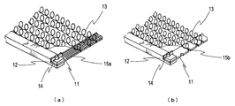
- FIG. 1A is a plan view showing a preferred embodiment of the elastic cushion material of the present invention
- FIG. 1B is a plan view showing an example of the stretched elastic cushion material of the present invention.
- the elastic cushion material 10 of the present invention includes a pair of corrosion-resistant metal thin plates 11 (hereinafter, also simply referred to as “metal thin plates”) arranged in parallel at intervals, and a fixing member 12 that fixes the pair of metal thin plates 11.
- a metal elastic body 13 (a metal coil body in the illustrated example) is wound between a pair of thin metal plates 11.
- the fixing member 12 is detachably attached from the pair of metal thin plates 11 by the fixing means 14 (FIG. 1A), and the elastic cushion material 10 is deformed to be stretchable by removing the fixing member 12. (FIG. 1B).
- the fixing member 12 is a pair of rods that fix both ends of the thin metal plate 11, but in the elastic cushion material of the present invention, the embodiment is not limited to this, and a pair of metals As long as the thin plate 11 can be fixed, the fixing member may fix the pair of metal thin plates 11 with only one fixing member at the center, or may be fixed using a plurality of fixing members.
- the conventional elastic cushion material is obtained by winding a metal coil 22 around a corrosion-resistant frame 21 made of a corrosion-resistant metal round bar (see FIGS. 5A and 5B), but the elastic cushion material 10 of the present invention.
- a metal elastic body 13 is wound between a pair of thin metal plates 11 arranged in parallel at intervals. If a metal thin plate 11 having a thickness smaller than that of a conventionally used metal round bar is used, the thickness can be made thinner than that of a conventional elastic cushion material 20.
- the elastic cushion material 10 of this invention can be arrange
- the metal thin plate 11 is preferably made of a metal or metal alloy exhibiting good corrosion resistance.
- an elastic cushion material is disposed on the cathode side, nickel, nickel alloy, stainless steel, or an elastic cushion material is disposed on the anode side.
- FIG. 2 is a perspective view of a fixing portion between the metal thin plate 11 and the fixing member 12 of the elastic cushion material of the present invention.
- a fixing member 12 is used to fix a pair of thin metal plates 11, and both are fixed by a known fixing means 14.
- a notch is provided at the end of the fixing member 12, and the thin metal plate 11 is inserted into the notch and fixed by fixing means 14 (in the illustrated example, a butterfly bolt).
- fixing means 14 in the illustrated example, a butterfly bolt
- the fixing member 12 is for preventing the elastic cushion material 10 from being deformed by the tension of the metal elastic body 13, and therefore, the fixing member 12 is not particularly limited as long as it can withstand the tension of the metal elastic body 13. Absent. For example, a rod-shaped body made of metal or plastic can be used. In addition, since the elastic cushion material 10 of this invention removes the fixing member 12 and uses it at the time of the use, it is also possible to use a large diameter member. Further, in the elastic cushion material 10 of the present invention, the fixing means 14 for attaching the fixing member 12 to the metal thin plate 11 is not particularly limited, and known fixing means can be used. Can be mentioned.
- the elastic cushion material 10 of the present invention has an effect other than the effect that it can be attached to an ion exchange membrane electrolytic cell having a small gap between an electrode and an electrode current collector plate in which a conventional elastic cushion material cannot be disposed.
- the following effects are also obtained.
- the corrosion-resistant frame 21 used in the conventional elastic cushion material 20 is a rectangular frame made of a corrosion-resistant metal round bar or the like (FIG. 5A)
- a metal coil body 22 is wound as a metal elastic body. Except for the pair of rotating metal round bars, they were not necessary after being mounted on the ion exchange membrane electrolytic cell, resulting in waste.
- the elastic cushion material 10 of the present invention can eliminate such waste because the fixing member 12 can be freely detached.
- the elastic cushion material 10 can be expanded and contracted, so that it is possible to cope with electrolytic cells of various sizes. Furthermore, since the elastic cushion material 10 of the present invention is used by expanding the distance between the pair of thin metal plates 11 during use, the state before use is compact, and is excellent in terms of storage space and transportation cost. Furthermore, even when a metal elastic body having a larger tension than that of the metal coil body 22 used in the conventional elastic cushion material 20 is used, it is not necessary to add a reinforcing member to the rectangular frame, resulting in an increase in cost. It can be introduced without.
- the metal elastic body 13 is made of a conductive material and has an elastic property, and power can be supplied by pressing a flexible electrode against the ion exchange membrane.
- a metal coil body In addition to the metal coil body, for example, a corrugated metal thin wire may be used.
- the material thereof is, for example, nickel showing good corrosion resistance, nickel showing good corrosion resistance, such as nickel, nickel alloy, stainless steel, or copper having low specific resistance. It is possible to use a wire produced by coating the wire with plating or the like, and a metal coil body can be produced by processing this wire into a spiral coil by roll processing.
- the cross-sectional shape of the obtained wire is preferably a circle, an ellipse, a rectangle with rounded corners, or the like from the viewpoint of preventing damage to the ion exchange membrane.
- NiW2201 nickel wire having a diameter of 0.17 mm
- a coil wire having a cross-sectional shape of about 0.05 mm ⁇ 0.5 mm with rounded corners and a winding diameter of about 6 mm is obtained. be able to.
- the ion exchange membrane electrolytic cell of this invention is partitioned into an anode chamber containing an anode and a cathode chamber containing a cathode by an ion exchange membrane, and at least one of the anode chamber and the cathode chamber has the elasticity of the present invention.
- the cushion material 10 is arranged.
- the elastic cushion material 10 of the present invention is disposed between at least one of a cathode and a cathode current collector and between an anode and an anode current collector, or a bipolar ion In the exchange membrane electrolytic cell, the elastic cushion material 10 of the present invention may be disposed between at least one of the cathode and the cathode partition and between the anode and the anode partition.
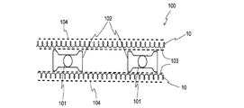
- FIG. 3 is a schematic diagram showing an example in which the cathode of the cathode unit of the unipolar ion exchange membrane electrolytic cell according to one preferred embodiment of the present invention and the cathode current collector are electrically connected via an elastic cushion material. It is a top view.
- the elastic cushion material 10 of the present invention is disposed between the hydrogen generating cathode 104 and the cathode current collector 103.
- a pair of conductive rods 101 that face in the vertical direction are erected in the electrolytic cell, and a catholyte circulation energization member 102 is installed around the electroconductive rod 101.
- a cathode current collector 103 is electrically connected along the surface.
- the elastic cushion material of the present invention can be suitably used for an electrolytic cell with a small gap such that the gap between the electrode and the electrode current collector plate is 1 mm or less, but applicable electrolytic cells are limited to this. is not. Even in an electrolytic cell in which a conventional elastic cushion material can be arranged, the use of the elastic cushion material of the present invention can reduce the side material around which the metal elastic body is not wound, and the elastic cushion. Storage space and transportation costs can be reduced compared to materials.
- the elastic cushion material 10 is not necessarily fixed to the cathode current collector 103 or the hydrogen generating cathode 104 by welding or the like, but may be fixed.
- the fixing means include means for fixing the elastic cushion material to an existing rigid cathode or the like (expanded metal cathode) using a Teflon (registered trademark) pin or the like. it can.
- electricity is flowed by a contact energization method.
- the assembly of the elastic cushion material using a metal elastic body is an operation outside the electrolytic cell, so it can be easily performed, and the obtained elastic cushion material is the target in the electrolytic cell when the electrolytic cell is assembled.
- the electrode and the mounted current collector may be mounted so as to be electrically connected.
- the diameter of the metal coil body (the apparent diameter of the coil) is usually 10 by being mounted in the electrolytic cell.
- the elasticity shrinks to ⁇ 70%, and this elasticity facilitates power supply to the electrode by elastically connecting the anode and the anode current collector or the cathode and the cathode current collector.
- the coil diameter is constant, the use of a metal coil body with a small wire diameter inevitably increases the number of contact points between the electrode or current collector and the elastic cushion material, thereby enabling uniform contact.
- the elastic cushion material 10 after being mounted on the electrolytic cell is held in shape by the pair of thin metal plates 11, it hardly receives plastic deformation, and most of the electrolytic cell is also disassembled and reassembled. Can be reused if.
- the elastic cushion material 10 or the like is positioned between at least one electrode and the electrode current collector, and thereafter If assembled as usual, an ion exchange membrane electrolytic cell in which the elastic cushion material 10 or the like is held at a predetermined position can be obtained.
- the electrode catalyst may be supported on the metal elastic body of the elastic cushion material 10. That is, by making the metal elastic body itself function as an electrode, there is no need to dispose the hydrogen generating cathode 104 in the illustrated example, and the merit that the number of parts can be reduced can be obtained.
- a coating of an electrode catalyst material such as a platinum group metal-containing layer, a Raney nickel-containing layer, or an activated carbon-containing nickel layer may be formed on the surface of the metal elastic body.
- Raney nickel catalyst may be subjected to dispersion plating with nickel on the surface of the elastic body, or a precious metal light metal such as hexachloroplatinum may be subjected to plating treatment such as brush plating, or may be baked.
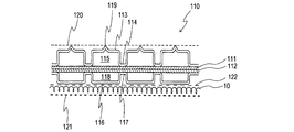
- FIG. 4 is a schematic diagram showing an example in which a hydrogen generating cathode and a cathode partition wall of a bipolar ion exchange membrane electrolytic cell unit according to another preferred embodiment of the present invention are electrically connected via an elastic cushion material. It is a top view.
- an anode holding member 113 integrated in the illustrated example facing the vertical direction on the anode side of the joined anode partition 111 and cathode partition 112.
- each member 113 Is fixed by joining the belt-like joining portion 114 to the anode partition wall 111, and an anolyte circulation passage 115 is secured in each member 113. Further, a cathode holding member 116 corresponding to the anode holding member 113 is fixed to the cathode side of the joining partition by joining the strip-shaped joining portion 117 to the cathode partition 112, and each cathode holding member 116 has a catholyte circulation path. 118 is secured. A convex portion 119 is formed outside the center of the anode holding member 113, and power is supplied to the expanded metal anode 120 through the convex portion 119.
- the elastic cushion material 10 of the present invention is in electrical contact with the flat surface of the cathode holding member 116, and the hydrogen generating cathode 121 is electrically connected to the outside of the flat surface of the cathode holding member 116. Power is supplied to the hydrogen generating cathode 121 through 10.
- the bipolar ion exchange membrane electrolytic cell 110 a figure is provided between at least one of the hydrogen generating cathode 121 and the cathode partition 112 and between the anode 120 and the anode partition 111.
- an elastic cushion material obtained by removing the fixing member 12 from the elastic cushion material 10 of the present invention is disposed between the hydrogen generating cathode 121 and the cathode partition 112.
- the elastic cushion material of the present invention includes an electrode, an electrode current collector plate,
- the applicable electrolytic cell is not limited to this.
- the use of the elastic cushion material of the present invention can reduce the side material around which the metal elastic body is not wound, Storage space and transportation costs can be reduced compared to elastic cushion materials.
- a mesh 122 is disposed in order to prevent the elastic cushion material 10 from falling.
- the details of the elastic cushion material according to the present embodiment are the same as those of the elastic cushion material 10 used in the above-described monopolar ion exchange membrane electrolytic cell.
- the cathode holding member 113 is disposed between the elastic cushion material 10 and the cathode partition 112.
- the present invention is not limited to this configuration, and the elastic cushion is provided between the electrode and the partition. It is only necessary that a material is disposed and electrically connected via the elastic cushion material.
- an electrode catalyst may be supported on the metal elastic body of the elastic cushion material 10. That is, by causing the metal elastic body itself to function as an electrode, there is no need to dispose the electrode, the hydrogen generating cathode 121 in the illustrated example, and the merit that the number of parts can be reduced can be obtained.
- the ion exchange membrane electrolytic cell of the present invention has been described separately for the case where the ion exchange membrane electrolytic cell is a monopolar type and the case of a bipolar type, but the ion exchange membrane electrolytic cell of the present invention has the above-described configuration. It is only important to satisfy the above. For other structures, a conventionally used structure can be used as appropriate, and there is no particular limitation.
- the shape of the cathode current collector may be a mesh shape or a plate shape, and the shape is not particularly limited.
- the cathode is not particularly limited as long as it is pressed by the elastic cushion material 10 and comes into contact with the ion exchange membrane, and any cathode can be used as long as it is usually used for electrolysis.
- Ru-La-Pt system, Ru-Ce system, Pt-Ce system which has high activity even if the catalyst film is thin, has a smooth coating surface, and does not mechanically damage the ion exchange membrane.
- a pyrolytic active cathode selected from the group consisting of Pt—Ni-based materials.
Landscapes
- Chemical & Material Sciences (AREA)
- Engineering & Computer Science (AREA)
- Chemical Kinetics & Catalysis (AREA)
- Electrochemistry (AREA)
- Materials Engineering (AREA)
- Metallurgy (AREA)
- Organic Chemistry (AREA)
- Electrolytic Production Of Non-Metals, Compounds, Apparatuses Therefor (AREA)
Priority Applications (5)
| Application Number | Priority Date | Filing Date | Title |
|---|---|---|---|
| KR1020147034002A KR101848339B1 (ko) | 2012-06-13 | 2013-05-30 | 탄성 쿠션재 및 이것을 사용한 이온 교환막 전해조 |
| EP13804146.2A EP2862961B1 (en) | 2012-06-13 | 2013-05-30 | Elastic cushion material and ion exchange membrane electrolytic cell utilizing same |
| CN201380031146.6A CN104379815B (zh) | 2012-06-13 | 2013-05-30 | 弹性缓冲件和使用了该弹性缓冲件的离子交换膜电解槽 |
| US14/407,394 US10344386B2 (en) | 2012-06-13 | 2013-05-30 | Elastic cushion material and ion exchange membrane electrolytic cell utilizing same |
| IN2631MUN2014 IN2014MN02631A (cg-RX-API-DMAC7.html) | 2012-06-13 | 2013-05-30 |
Applications Claiming Priority (2)
| Application Number | Priority Date | Filing Date | Title |
|---|---|---|---|
| JP2012134271A JP5970250B2 (ja) | 2012-06-13 | 2012-06-13 | イオン交換膜電解槽用弾性クッション材 |
| JP2012-134271 | 2012-06-13 |
Publications (1)
| Publication Number | Publication Date |
|---|---|
| WO2013187242A1 true WO2013187242A1 (ja) | 2013-12-19 |
Family
ID=49758071
Family Applications (1)
| Application Number | Title | Priority Date | Filing Date |
|---|---|---|---|
| PCT/JP2013/065085 Ceased WO2013187242A1 (ja) | 2012-06-13 | 2013-05-30 | 弾性クッション材およびそれを用いたイオン交換膜電解槽 |
Country Status (7)
| Country | Link |
|---|---|
| US (1) | US10344386B2 (cg-RX-API-DMAC7.html) |
| EP (1) | EP2862961B1 (cg-RX-API-DMAC7.html) |
| JP (1) | JP5970250B2 (cg-RX-API-DMAC7.html) |
| KR (1) | KR101848339B1 (cg-RX-API-DMAC7.html) |
| CN (1) | CN104379815B (cg-RX-API-DMAC7.html) |
| IN (1) | IN2014MN02631A (cg-RX-API-DMAC7.html) |
| WO (1) | WO2013187242A1 (cg-RX-API-DMAC7.html) |
Families Citing this family (6)
| Publication number | Priority date | Publication date | Assignee | Title |
|---|---|---|---|---|
| JP5913693B1 (ja) | 2015-07-03 | 2016-04-27 | アクアエコス株式会社 | 電解装置及び電解オゾン水製造装置 |
| US10815578B2 (en) * | 2017-09-08 | 2020-10-27 | Electrode Solutions, LLC | Catalyzed cushion layer in a multi-layer electrode |
| PL3460101T3 (pl) * | 2017-09-21 | 2020-11-16 | Hymeth Aps | Elektroda do sposobu elektrolizy |
| JP7122181B2 (ja) * | 2018-07-06 | 2022-08-19 | 旭化成株式会社 | 電極構造体、電解セル及び電解槽 |
| JP7022918B2 (ja) * | 2018-07-13 | 2022-02-21 | パナソニックIpマネジメント株式会社 | 電解水生成装置 |
| US12644865B2 (en) | 2024-01-29 | 2026-06-02 | Honeywell International Inc. | Non-invasive advanced sensory system for real-time monitoring and diagnosis of electrolyzers, electrolytes and a lithium-ion battery (LIB) |
Citations (5)
| Publication number | Priority date | Publication date | Assignee | Title |
|---|---|---|---|---|
| JPS6353272A (ja) | 1986-08-22 | 1988-03-07 | Ulvac Corp | Cvd装置 |
| JP2004300547A (ja) * | 2003-03-31 | 2004-10-28 | Chlorine Eng Corp Ltd | 水素発生陰極を使用するイオン交換膜電解槽 |
| JP2004300543A (ja) | 2003-03-31 | 2004-10-28 | Chlorine Eng Corp Ltd | 電解用電極及びそれを使用するイオン交換膜電解槽 |
| JP2004300554A (ja) * | 2003-03-31 | 2004-10-28 | Chlorine Eng Corp Ltd | 液透過型ガス拡散陰極を使用するイオン交換膜電解槽 |
| JP2011117047A (ja) * | 2009-12-04 | 2011-06-16 | Tosoh Corp | イオン交換膜法電解槽 |
Family Cites Families (11)
| Publication number | Priority date | Publication date | Assignee | Title |
|---|---|---|---|---|
| US2967814A (en) * | 1958-10-15 | 1961-01-10 | Phelps Dodge Corp | Helix wire anode |
| JPS58133386A (ja) * | 1982-02-02 | 1983-08-09 | Chlorine Eng Corp Ltd | イオン交換膜電解槽 |
| US5231709A (en) * | 1990-09-26 | 1993-08-03 | Miller John E | Support deck for mattress or seat |
| JP3686270B2 (ja) * | 1998-12-10 | 2005-08-24 | 株式会社トクヤマ | 電解槽 |
| JP3807676B2 (ja) * | 2002-02-20 | 2006-08-09 | クロリンエンジニアズ株式会社 | イオン交換膜電解槽 |
| DE60302610T2 (de) * | 2002-04-05 | 2006-07-06 | Chlorine Engineers Corp., Ltd. | Ionenaustauschmembran-Elektrolyseur |
| US7548881B2 (en) | 2002-11-04 | 2009-06-16 | Tradebeam, Inc. | Systems and methods for producing documentary credit and conforming shipping documents |
| EP1464728B1 (en) | 2003-03-31 | 2016-03-09 | CHLORINE ENGINEERS CORP., Ltd. | Electrode for electrolysis and ion exchange membrane electrolytic cell |
| WO2010137284A1 (ja) | 2009-05-26 | 2010-12-02 | クロリンエンジニアズ株式会社 | ガス拡散電極装着イオン交換膜電解槽 |
| JP4846869B1 (ja) | 2010-09-07 | 2011-12-28 | クロリンエンジニアズ株式会社 | 電解用陰極構造体およびそれを用いた電解槽 |
| US8740196B2 (en) * | 2011-03-18 | 2014-06-03 | Jay Rodger Elrod | Drawbar spring coupler |
-
2012
- 2012-06-13 JP JP2012134271A patent/JP5970250B2/ja active Active
-
2013
- 2013-05-30 WO PCT/JP2013/065085 patent/WO2013187242A1/ja not_active Ceased
- 2013-05-30 EP EP13804146.2A patent/EP2862961B1/en not_active Not-in-force
- 2013-05-30 KR KR1020147034002A patent/KR101848339B1/ko not_active Expired - Fee Related
- 2013-05-30 IN IN2631MUN2014 patent/IN2014MN02631A/en unknown
- 2013-05-30 CN CN201380031146.6A patent/CN104379815B/zh active Active
- 2013-05-30 US US14/407,394 patent/US10344386B2/en active Active
Patent Citations (5)
| Publication number | Priority date | Publication date | Assignee | Title |
|---|---|---|---|---|
| JPS6353272A (ja) | 1986-08-22 | 1988-03-07 | Ulvac Corp | Cvd装置 |
| JP2004300547A (ja) * | 2003-03-31 | 2004-10-28 | Chlorine Eng Corp Ltd | 水素発生陰極を使用するイオン交換膜電解槽 |
| JP2004300543A (ja) | 2003-03-31 | 2004-10-28 | Chlorine Eng Corp Ltd | 電解用電極及びそれを使用するイオン交換膜電解槽 |
| JP2004300554A (ja) * | 2003-03-31 | 2004-10-28 | Chlorine Eng Corp Ltd | 液透過型ガス拡散陰極を使用するイオン交換膜電解槽 |
| JP2011117047A (ja) * | 2009-12-04 | 2011-06-16 | Tosoh Corp | イオン交換膜法電解槽 |
Non-Patent Citations (1)
| Title |
|---|
| See also references of EP2862961A4 |
Also Published As
| Publication number | Publication date |
|---|---|
| JP5970250B2 (ja) | 2016-08-17 |
| JP2013256706A (ja) | 2013-12-26 |
| KR101848339B1 (ko) | 2018-04-12 |
| CN104379815B (zh) | 2019-01-11 |
| EP2862961A4 (en) | 2016-01-20 |
| EP2862961B1 (en) | 2018-04-18 |
| IN2014MN02631A (cg-RX-API-DMAC7.html) | 2015-10-16 |
| KR20150022802A (ko) | 2015-03-04 |
| CN104379815A (zh) | 2015-02-25 |
| US20150122641A1 (en) | 2015-05-07 |
| US10344386B2 (en) | 2019-07-09 |
| EP2862961A1 (en) | 2015-04-22 |
Similar Documents
| Publication | Publication Date | Title |
|---|---|---|
| JP5945154B2 (ja) | イオン交換膜電解槽 | |
| JP5970250B2 (ja) | イオン交換膜電解槽用弾性クッション材 | |
| JP4846869B1 (ja) | 電解用陰極構造体およびそれを用いた電解槽 | |
| KR101944730B1 (ko) | 간편한 전극 체결 구조와 전해액 유동 가이드 구조를 구비한 전기분해장치 | |
| CN1537973B (zh) | 电解电极和离子交换膜电解池 | |
| JP2014037586A (ja) | 電解セル及び電解槽 | |
| JP4198726B2 (ja) | イオン交換膜電解槽 | |
| JP5493787B2 (ja) | イオン交換膜法電解槽 | |
| JP4246530B2 (ja) | 電解用電極及びそれを使用するイオン交換膜電解槽 | |
| WO2014199440A1 (ja) | イオン交換膜電解槽 | |
| JP2014221930A (ja) | イオン交換膜電解槽 | |
| JP3860132B2 (ja) | 水素発生陰極を使用するイオン交換膜電解槽 | |
| JP2013216922A (ja) | イオン交換膜電解槽 | |
| JP6026221B2 (ja) | プロジェクション溶接方法、およびイオン交換膜電解槽の製造方法 | |
| WO2016067389A1 (ja) | イオン交換膜電解槽 | |
| JP5653209B2 (ja) | イオン交換膜法電解槽 | |
| JP2014214350A (ja) | イオン交換膜電解槽 | |
| JP6318678B2 (ja) | イオン交換膜法電解槽 |
Legal Events
| Date | Code | Title | Description |
|---|---|---|---|
| 121 | Ep: the epo has been informed by wipo that ep was designated in this application |
Ref document number: 13804146 Country of ref document: EP Kind code of ref document: A1 |
|
| ENP | Entry into the national phase |
Ref document number: 20147034002 Country of ref document: KR Kind code of ref document: A |
|
| WWE | Wipo information: entry into national phase |
Ref document number: 14407394 Country of ref document: US |
|
| NENP | Non-entry into the national phase |
Ref country code: DE |
|
| WWE | Wipo information: entry into national phase |
Ref document number: 2013804146 Country of ref document: EP |