WO2013187198A1 - エキシマランプ - Google Patents
エキシマランプ Download PDFInfo
- Publication number
- WO2013187198A1 WO2013187198A1 PCT/JP2013/064208 JP2013064208W WO2013187198A1 WO 2013187198 A1 WO2013187198 A1 WO 2013187198A1 JP 2013064208 W JP2013064208 W JP 2013064208W WO 2013187198 A1 WO2013187198 A1 WO 2013187198A1
- Authority
- WO
- WIPO (PCT)
- Prior art keywords
- light emitting
- lamp
- excimer lamp
- external electrode
- sealing
- Prior art date
- Legal status (The legal status is an assumption and is not a legal conclusion. Google has not performed a legal analysis and makes no representation as to the accuracy of the status listed.)
- Ceased
Links
Images


Classifications
-
- H—ELECTRICITY
- H01—ELECTRIC ELEMENTS
- H01J—ELECTRIC DISCHARGE TUBES OR DISCHARGE LAMPS
- H01J61/00—Gas-discharge or vapour-discharge lamps
- H01J61/02—Details
- H01J61/04—Electrodes; Screens; Shields
- H01J61/06—Main electrodes
-
- H—ELECTRICITY
- H01—ELECTRIC ELEMENTS
- H01J—ELECTRIC DISCHARGE TUBES OR DISCHARGE LAMPS
- H01J61/00—Gas-discharge or vapour-discharge lamps
- H01J61/02—Details
- H01J61/54—Igniting arrangements, e.g. promoting ionisation for starting
-
- H—ELECTRICITY
- H01—ELECTRIC ELEMENTS
- H01J—ELECTRIC DISCHARGE TUBES OR DISCHARGE LAMPS
- H01J65/00—Lamps without any electrode inside the vessel; Lamps with at least one main electrode outside the vessel
- H01J65/04—Lamps in which a gas filling is excited to luminesce by an external electromagnetic field or by external corpuscular radiation, e.g. for indicating plasma display panels
- H01J65/042—Lamps in which a gas filling is excited to luminesce by an external electromagnetic field or by external corpuscular radiation, e.g. for indicating plasma display panels by an external electromagnetic field
- H01J65/046—Lamps in which a gas filling is excited to luminesce by an external electromagnetic field or by external corpuscular radiation, e.g. for indicating plasma display panels by an external electromagnetic field the field being produced by using capacitive means around the vessel
Definitions
- the present invention relates to an excimer lamp, and more particularly, to an excimer lamp in which an external electrode is disposed on the outer surface of an arc tube and an internal electrode is disposed in the arc tube.
- FIG. 4 shows the structure of an arc tube 1 made of an ultraviolet light transmissive quartz glass tube.
- the arc tube 1 is formed of a light emitting portion 2 in which a luminescent gas is sealed, and the glass tube is crushed at both ends thereof. And sealing portions 3 and 3.
- a mesh-like external electrode 4 is provided on the outer surface of the light-emitting portion 2 of the arc tube 1 so as to surround it, and an internal electrode 5 is disposed in the tube axis direction inside the internal electrode 5.
- An external lead 7 is connected to the other end of the metal foil 6, and the external lead 7 projects outward from the end of the sealing portion 3.
- a high frequency high voltage is applied between the inner and outer electrodes at the time of starting the lamp, and the outer electrode 4 and the inner electrode 5 form a tube wall of the arc tube 1 made of a dielectric material and a layer of luminous gas. A discharge occurs as if sandwiched, and the luminescent gas emits excimer light.
- the problem to be solved by the present invention is an arc tube comprising a light emitting portion in which a luminescent gas is sealed, sealing portions formed at both ends thereof, and an external portion disposed on the outer surface of the light emitting portion.
- a luminescent gas is sealed, sealing portions formed at both ends thereof, and an external portion disposed on the outer surface of the light emitting portion.
- an end of the external electrode extends and is wound around a root portion on the sealing portion side of the light emitting portion of the arc tube.
- the sealing portion may have a pinch seal structure in which a metal foil is embedded.
- the end portion of the external electrode disposed on the outer surface of the light emitting portion of the arc tube extends and is wound around the root portion on the sealing portion side of the light emitting portion.
- the external electrode exists on the surface of the reduced diameter portion where the outer diameter from the portion to the sealing portion gradually decreases, and the external electrode and the internal electrode in the light emitting portion are physically close to each other and approach the potential.
- electric discharge is likely to occur between the internal electrode and the external electrode via a dielectric (a luminous tube), which greatly improves the startability of the lamp and reduces the lamp voltage. Good startability can be obtained.
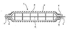
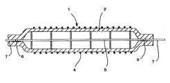
- the side view of the excimer lamp of this invention The side sectional view of the excimer lamp of the present invention.
- FIG. 1 and FIG. 2 show aspects of the external electrode in the excimer lamp of the present invention.
- the light emitting tube 1 made of quartz glass includes a light emitting portion 2 and sealing portions 3 and 3, and, for example, xenon (Xe) is sealed in the light emitting portion 2 as an excimer light emission gas from 20 kPa to 200 kPa.
- the sealing part 3 is comprised by the pinch seal part formed by heating and crushing the edge part of the quartz glass tube which comprises the arc_tube
- FIG. A mesh-like external electrode 4 is disposed on the outer surface of the light emitting unit 2, and an internal electrode 5 is disposed inside.
- the internal electrode 5 is made of a rod-shaped metal rod disposed along the tube axis center inside the arc tube 1, and both ends thereof are connected to a metal foil 6 embedded in the sealing portion 3. At the same time, it is supported by the glass of the sealing portion 3.
- An external lead 7 is connected to the other end of the metal foil 6 and protrudes from the end of the sealing portion 3 to the outside.
- the external electrode 4 is made of a fine metal wire, is covered around the arc tube 1 and extends along the circumferential direction and the axial direction.
- the external electrode 4 is a seamless electrode formed by knitting a metal wire into a cylindrical shape, and light from the arc tube 1 can be transmitted between the metal wires.
- the end portion 4 a of the external electrode 4 extends from the light emitting portion 2 and is wound around the root portion of the light emitting portion 2 on the sealing portion 3 side.
- FIG. 3 which is an enlarged view of the end of FIG. 2
- the outer diameter of the end 4 a of the external electrode 4 gradually decreases at least from the light emitting unit 2 toward the sealing unit 3. It exists over the reduced diameter portion 8.
- the distance between the external electrode 4 and the internal electrode 5 is closer than the other portions, and the minute diameter formed in the reduced diameter portion 8.
- the portion corresponding to the gap S is a part where the dielectric approaches the internal electrode 5 and the potential difference between the external electrode 4 and the internal electrode 5 becomes extremely small, so that a discharge through the dielectric is likely to occur. The excimer lamp starts well.
- the structure of the sealing portion 3 has been described as a pinch seal structure, but is not limited to this, and a shrink seal structure in which the diameter is reduced from the entire circumference of the outer periphery of the arc tube 1 can be employed. It is. Also in this case, since a minute gap is formed between the internal electrode 5 and the inner surface of the light emitting portion 3 in the reduced diameter portion, the same effect can be obtained.
- the excimer lamp according to the present invention has the end of the external electrode disposed on the outer surface of the light emitting portion of the arc tube extending and wound around the root portion on the sealing portion side of the light emitting portion. Therefore, the external electrode exists on the surface of the reduced diameter portion where the outer diameter from the light emitting portion to the sealing portion gradually decreases, and the external electrode and the internal electrode in the light emitting portion are physically close to each other, and the potential is reduced. As a result, the discharge is likely to occur between the internal electrode and the external electrode via a dielectric (a light emitting tube), thereby greatly improving the startability of the lamp and reducing the lamp voltage. Even if kept low, good startability can be obtained.
Landscapes
- Physics & Mathematics (AREA)
- Electromagnetism (AREA)
- Engineering & Computer Science (AREA)
- Plasma & Fusion (AREA)
- Vessels And Coating Films For Discharge Lamps (AREA)
Priority Applications (1)
| Application Number | Priority Date | Filing Date | Title |
|---|---|---|---|
| CN201380025232.6A CN104303261B (zh) | 2012-06-12 | 2013-05-22 | 准分子灯 |
Applications Claiming Priority (2)
| Application Number | Priority Date | Filing Date | Title |
|---|---|---|---|
| JP2012-132499 | 2012-06-12 | ||
| JP2012132499A JP5672562B2 (ja) | 2012-06-12 | 2012-06-12 | エキシマランプ |
Publications (1)
| Publication Number | Publication Date |
|---|---|
| WO2013187198A1 true WO2013187198A1 (ja) | 2013-12-19 |
Family
ID=49758028
Family Applications (1)
| Application Number | Title | Priority Date | Filing Date |
|---|---|---|---|
| PCT/JP2013/064208 Ceased WO2013187198A1 (ja) | 2012-06-12 | 2013-05-22 | エキシマランプ |
Country Status (3)
| Country | Link |
|---|---|
| JP (1) | JP5672562B2 (https=) |
| CN (1) | CN104303261B (https=) |
| WO (1) | WO2013187198A1 (https=) |
Families Citing this family (3)
| Publication number | Priority date | Publication date | Assignee | Title |
|---|---|---|---|---|
| JP6428196B2 (ja) | 2014-11-25 | 2018-11-28 | ウシオ電機株式会社 | エキシマ放電ランプ装置 |
| CN106783526A (zh) * | 2016-12-26 | 2017-05-31 | 上海开若纳科技有限公司 | 一种大尺寸准分子灯 |
| JP7132540B2 (ja) * | 2018-06-13 | 2022-09-07 | ウシオ電機株式会社 | エキシマランプ |
Citations (6)
| Publication number | Priority date | Publication date | Assignee | Title |
|---|---|---|---|---|
| JPH09283092A (ja) * | 1996-04-19 | 1997-10-31 | Stanley Electric Co Ltd | 蛍光ランプ |
| JPH10112290A (ja) * | 1996-10-08 | 1998-04-28 | Ushio Inc | 希ガス放電ランプ |
| JP2002110103A (ja) * | 2000-09-28 | 2002-04-12 | Toshiba Lighting & Technology Corp | 誘電体バリヤ放電ランプ、誘電体バリヤ放電ランプ装置および紫外線洗浄装置 |
| JP2004186068A (ja) * | 2002-12-05 | 2004-07-02 | Ushio Inc | エキシマランプ発光装置 |
| JP2006024382A (ja) * | 2004-07-06 | 2006-01-26 | Ushio Inc | エキシマランプ |
| JP2011210542A (ja) * | 2010-03-30 | 2011-10-20 | Ushio Inc | 高圧放電ランプ |
Family Cites Families (1)
| Publication number | Priority date | Publication date | Assignee | Title |
|---|---|---|---|---|
| CN2886800Y (zh) * | 2006-01-25 | 2007-04-04 | 上海国达特殊光源有限公司 | 准分子放电管 |
-
2012
- 2012-06-12 JP JP2012132499A patent/JP5672562B2/ja not_active Expired - Fee Related
-
2013
- 2013-05-22 WO PCT/JP2013/064208 patent/WO2013187198A1/ja not_active Ceased
- 2013-05-22 CN CN201380025232.6A patent/CN104303261B/zh not_active Expired - Fee Related
Patent Citations (6)
| Publication number | Priority date | Publication date | Assignee | Title |
|---|---|---|---|---|
| JPH09283092A (ja) * | 1996-04-19 | 1997-10-31 | Stanley Electric Co Ltd | 蛍光ランプ |
| JPH10112290A (ja) * | 1996-10-08 | 1998-04-28 | Ushio Inc | 希ガス放電ランプ |
| JP2002110103A (ja) * | 2000-09-28 | 2002-04-12 | Toshiba Lighting & Technology Corp | 誘電体バリヤ放電ランプ、誘電体バリヤ放電ランプ装置および紫外線洗浄装置 |
| JP2004186068A (ja) * | 2002-12-05 | 2004-07-02 | Ushio Inc | エキシマランプ発光装置 |
| JP2006024382A (ja) * | 2004-07-06 | 2006-01-26 | Ushio Inc | エキシマランプ |
| JP2011210542A (ja) * | 2010-03-30 | 2011-10-20 | Ushio Inc | 高圧放電ランプ |
Also Published As
| Publication number | Publication date |
|---|---|
| JP2013257999A (ja) | 2013-12-26 |
| JP5672562B2 (ja) | 2015-02-18 |
| CN104303261A (zh) | 2015-01-21 |
| CN104303261B (zh) | 2016-10-05 |
Similar Documents
| Publication | Publication Date | Title |
|---|---|---|
| JP4134793B2 (ja) | 光源装置 | |
| JP4760945B2 (ja) | 光源装置 | |
| JP5672562B2 (ja) | エキシマランプ | |
| JP5167955B2 (ja) | キセノンランプ | |
| JP6557011B2 (ja) | エキシマランプ | |
| JP6212850B2 (ja) | エキシマランプ | |
| KR101928599B1 (ko) | 쇼트 아크형 플래시 램프 및 광원 장치 | |
| JP2008293912A (ja) | 高圧放電灯およびこれを用いた光源装置 | |
| JP5051401B2 (ja) | 高圧放電ランプ | |
| JP2013257999A5 (https=) | ||
| US7893618B2 (en) | Gas discharge lamp | |
| JP5257270B2 (ja) | 放電ランプ装置 | |
| JP6007656B2 (ja) | エキシマランプ | |
| JP6303946B2 (ja) | 希ガス蛍光ランプ | |
| JP5640998B2 (ja) | エキシマランプ | |
| CN102725820A (zh) | 高压放电灯 | |
| JP2010073624A (ja) | 高圧放電ランプおよび照明装置 | |
| TW201943098A (zh) | 準分子燈、光照射裝置、及臭氧產生裝置 | |
| WO2009144904A1 (ja) | 反射鏡付放電ランプ | |
| JP5629985B2 (ja) | 放電ランプ装置 | |
| CN103563047B (zh) | 具有辅助点火器的高压放电灯 | |
| CN102479666A (zh) | 放电灯装置 | |
| JP2020091941A (ja) | ショートアーク型放電ランプ | |
| JP2016100292A (ja) | 両端封止型ショートアークフラッシュランプ | |
| JP2003197151A (ja) | メタルハライドランプ |
Legal Events
| Date | Code | Title | Description |
|---|---|---|---|
| 121 | Ep: the epo has been informed by wipo that ep was designated in this application |
Ref document number: 13805011 Country of ref document: EP Kind code of ref document: A1 |
|
| NENP | Non-entry into the national phase |
Ref country code: DE |
|
| 122 | Ep: pct application non-entry in european phase |
Ref document number: 13805011 Country of ref document: EP Kind code of ref document: A1 |