WO2013187155A1 - 荷電粒子ビーム発生装置、荷電粒子線装置、高電圧発生装置、および高電位装置 - Google Patents
荷電粒子ビーム発生装置、荷電粒子線装置、高電圧発生装置、および高電位装置 Download PDFInfo
- Publication number
- WO2013187155A1 WO2013187155A1 PCT/JP2013/062896 JP2013062896W WO2013187155A1 WO 2013187155 A1 WO2013187155 A1 WO 2013187155A1 JP 2013062896 W JP2013062896 W JP 2013062896W WO 2013187155 A1 WO2013187155 A1 WO 2013187155A1
- Authority
- WO
- WIPO (PCT)
- Prior art keywords
- electrodes
- potential
- electrode
- housing
- charged particle
- Prior art date
- Legal status (The legal status is an assumption and is not a legal conclusion. Google has not performed a legal analysis and makes no representation as to the accuracy of the status listed.)
- Ceased
Links
Images


Classifications
-
- H—ELECTRICITY
- H01—ELECTRIC ELEMENTS
- H01J—ELECTRIC DISCHARGE TUBES OR DISCHARGE LAMPS
- H01J37/00—Discharge tubes with provision for introducing objects or material to be exposed to the discharge, e.g. for the purpose of examination or processing thereof
- H01J37/02—Details
- H01J37/04—Arrangements of electrodes and associated parts for generating or controlling the discharge, e.g. electron-optical arrangement or ion-optical arrangement
- H01J37/06—Electron sources; Electron guns
- H01J37/067—Replacing parts of guns; Mutual adjustment of electrodes
-
- H—ELECTRICITY
- H01—ELECTRIC ELEMENTS
- H01J—ELECTRIC DISCHARGE TUBES OR DISCHARGE LAMPS
- H01J27/00—Ion beam tubes
- H01J27/02—Ion sources; Ion guns
- H01J27/022—Details
- H01J27/024—Extraction optics, e.g. grids
-
- H—ELECTRICITY
- H01—ELECTRIC ELEMENTS
- H01J—ELECTRIC DISCHARGE TUBES OR DISCHARGE LAMPS
- H01J29/00—Details of cathode-ray tubes or of electron-beam tubes of the types covered by group H01J31/00
- H01J29/46—Arrangements of electrodes and associated parts for generating or controlling the ray or beam, e.g. electron-optical arrangement
- H01J29/48—Electron guns
- H01J29/485—Construction of the gun or of parts thereof
-
- H—ELECTRICITY
- H01—ELECTRIC ELEMENTS
- H01J—ELECTRIC DISCHARGE TUBES OR DISCHARGE LAMPS
- H01J37/00—Discharge tubes with provision for introducing objects or material to be exposed to the discharge, e.g. for the purpose of examination or processing thereof
- H01J37/02—Details
- H01J37/026—Means for avoiding or neutralising unwanted electrical charges on tube components
-
- H—ELECTRICITY
- H01—ELECTRIC ELEMENTS
- H01J—ELECTRIC DISCHARGE TUBES OR DISCHARGE LAMPS
- H01J37/00—Discharge tubes with provision for introducing objects or material to be exposed to the discharge, e.g. for the purpose of examination or processing thereof
- H01J37/02—Details
- H01J37/04—Arrangements of electrodes and associated parts for generating or controlling the discharge, e.g. electron-optical arrangement or ion-optical arrangement
- H01J37/06—Electron sources; Electron guns
- H01J37/073—Electron guns using field emission, photo emission, or secondary emission electron sources
-
- H—ELECTRICITY
- H01—ELECTRIC ELEMENTS
- H01J—ELECTRIC DISCHARGE TUBES OR DISCHARGE LAMPS
- H01J37/00—Discharge tubes with provision for introducing objects or material to be exposed to the discharge, e.g. for the purpose of examination or processing thereof
- H01J37/02—Details
- H01J37/24—Circuit arrangements not adapted to a particular application of the tube and not otherwise provided for
- H01J37/241—High voltage power supply or regulation circuits
-
- H—ELECTRICITY
- H01—ELECTRIC ELEMENTS
- H01J—ELECTRIC DISCHARGE TUBES OR DISCHARGE LAMPS
- H01J37/00—Discharge tubes with provision for introducing objects or material to be exposed to the discharge, e.g. for the purpose of examination or processing thereof
- H01J37/02—Details
- H01J37/248—Components associated with high voltage supply
-
- H—ELECTRICITY
- H01—ELECTRIC ELEMENTS
- H01J—ELECTRIC DISCHARGE TUBES OR DISCHARGE LAMPS
- H01J2237/00—Discharge tubes exposing object to beam, e.g. for analysis treatment, etching, imaging
- H01J2237/16—Vessels
-
- H—ELECTRICITY
- H01—ELECTRIC ELEMENTS
- H01J—ELECTRIC DISCHARGE TUBES OR DISCHARGE LAMPS
- H01J37/00—Discharge tubes with provision for introducing objects or material to be exposed to the discharge, e.g. for the purpose of examination or processing thereof
- H01J37/02—Details
- H01J37/16—Vessels; Containers
Definitions
- the present invention relates to a technique for insulating a high voltage device, and in particular, to a charged particle beam generator, a charged particle beam device, a high voltage generator, and a high potential device to which this technology is applied.
- the charged particle beam apparatus is an apparatus that accelerates particles (charged particles) having charges such as electrons and cations with an electric field and irradiates a sample.
- a charged particle beam apparatus performs observation, analysis, processing, and the like of a sample by utilizing an interaction between the sample and charged particles.
- Examples of the charged particle beam apparatus include an electron microscope, an electron beam drawing apparatus, an ion processing apparatus, and an ion microscope.
- an electron microscope is an apparatus that performs observation of a fine structure and analysis of constituent elements by irradiating a sample with electrons and detecting an interaction between the electron and the sample as a signal.
- an electron microscope will be described.
- Electron microscopes often have an electron acceleration mechanism that uses a negative high voltage potential.
- the electron microscope includes an electron source that generates free electrons in a vacuum.
- An electron microscope generates a large number of electron bundles (electron beams) having a constant kinetic energy by accelerating free electrons from an electron source by a potential difference.
- Many electron microscopes employ a structure in which an electron source is placed on a cathode having a negative high voltage potential and the anode is grounded in order to obtain an electron beam. Due to the potential difference between the cathode and the anode, the electrons are accelerated to a desired energy and become electron beams.
- the part of the electron microscope that generates the electron beam is called an electron gun.
- the energy of the electron beam generated by the electron gun matches the high voltage potential of the electron source portion of the electron gun.
- Examples of the electron microscope include a scanning electron microscope, a scanning transmission electron microscope, and a transmission electron microscope.
- a scanning electron microscope is a device that uses secondary electrons or reflected electrons from the surface of a sample, and the required energy of the electron beam is about 30 kV at the maximum.
- a scanning transmission electron microscope and a transmission electron microscope are devices that observe electrons that are transmitted through a sample or scattered within the sample, and the energy of the required electron beam is mainly 100 kV or more.
- many electron microscopes have a structure in which the energy of the electron beam is given by the high voltage potential of the electron source section. Therefore, an electron microscope that requires higher electron beam energy requires a structure that stably maintains the high-voltage potential of the electron source portion from the surrounding ground potential portion.
- an acceleration tube structure is often adopted.
- an insulator tube and a metal ring are alternately laminated between an electron source portion (cathode) that is maintained at a negative high voltage potential and an anode that is an exit of the electron beam and takes a ground potential.
- the structure (acceleration tube) is incorporated.
- an accelerating tube structure is adopted for the following reason.
- the equipotential lines are not distributed smoothly on the insulator between the electrodes at both ends, but the equipotential lines are spaced closer to either end of the long insulator.
- the narrow part (electric field concentration part) is made.
- the accelerating tube structure has a laminated structure of an insulator tube and an intermediate electrode, and the intermediate electrode is forcibly given a potential intermediate between the electron source and the ground potential by using a bleeder resistance.
- the insulator tube only needs to perform the function of insulating the electrodes at both ends of the insulator tube, and the high potential portion can be stably maintained.
- the acceleration tube has a potential difference of, for example, a maximum of 200 kV between the surrounding ground potential portion.
- This potential difference may cause discharge in the space between the high potential portion of the accelerating tube and the ground potential portion of the container, and the electron gun is required to have a function (insulating portion) for maintaining this potential difference stably.
- Patent Document 1 discloses a structure in which the periphery of an acceleration tube is surrounded by a metal container.
- a metal container is provided around the acceleration tube, and this is set to the ground potential.
- the container in order to prevent discharge from occurring in the space between the high potential portion of the accelerating tube and the ground potential portion of the container, the container is filled with an insulating gas or an insulating liquid. This prevents discharge from occurring between electrodes having a potential difference.
- an insulating gas or an insulating liquid (hereinafter referred to as “insulating substance”) is used, but the insulating substance is used to reduce the size, weight, and cost of the electron gun device. It should have as high insulation performance as possible.
- the insulating gas for example, SF 6 (sulfur hexafluoride) may be used.
- As the insulating liquid rapeseed oil, fluorine-based inert liquid, or the like may be used. While these insulating materials have excellent insulating performance, SF 6 is a global warming gas, and there is a demand for limiting the amount used. However, there is almost no insulating gas that is more environmentally friendly than SF 6 and has superior insulating performance. Therefore, there is a need for a structure that does not use insulating gas or that can reduce the amount of insulating gas used.
- an insulating liquid such as rapeseed oil
- the presence of air bubbles degrades the insulation performance, making it difficult to open and close the device. Therefore, it is difficult to use in an apparatus such as an electron gun that requires periodic disassembly maintenance.
- an insulating solid such as a resin around the acceleration tube. Insulating solids generally have better insulating performance than insulating gases and liquids, but once an insulating solid is filled and solidified, disassembly and maintenance are almost impossible.
- some high-voltage devices have a multi-layered electrode array between the high potential portion of the device and the ground potential portion, and the electrode rows are sequentially placed in the middle.
- devices that have a potential. Examples of devices having this structure include high voltage generators such as Cockcroft-Walton type and bandegraph type, electrostatic accelerator tubes of particle accelerators, and the like.
- These high-voltage devices also have a common technical problem of insulating the entire high potential portion from the surrounding ground potential container. Therefore, these high-voltage devices also have the above-described problems when using an insulating gas or an insulating liquid.
- the present invention provides a technique that does not use a gas or liquid insulating material in a high-voltage device, or that can reduce the amount of these materials used while improving maintainability.
- a charged particle source a plurality of first electrodes arranged along an irradiation direction of charged particles from the charged particle source, and a plurality of insulating members arranged between the first electrodes And a housing provided around the plurality of first electrodes, wherein the housing is formed of an insulating solid material, and the housing is proximate to the plurality of first electrodes.
- a plurality of second electrodes disposed at positions, wherein at least one of the plurality of second electrodes is electrically connected to at least one of the plurality of first electrodes,
- a charged particle beam generator in which each of the electrodes has the same potential as the potential of the adjacent first electrode.
- a charged particle beam apparatus provided with the charged particle beam generator mentioned above is provided.
- the plurality of first electrodes stacked on the ground potential surface, the plurality of insulating members disposed between the first electrodes, and the periphery of the plurality of first electrodes A plurality of second electrodes disposed in positions adjacent to the plurality of first electrodes.
- the housing is formed of an insulating solid material.
- at least one of the plurality of second electrodes is electrically connected to at least one of the plurality of first electrodes, and each of the plurality of second electrodes is adjacent to the first electrode.
- a high voltage generator is provided that has the same potential as the electrode.
- a charged particle beam apparatus provided with the high voltage generator mentioned above is provided.
- a high potential portion where a high potential is generated, at least one first electrode disposed between the high potential portion and the ground potential plane, the high potential portion and the first potential
- a housing provided around the electrode, wherein the housing is formed of an insulating solid material, and the housing corresponds to a predetermined potential interval from the ground potential surface to the high potential portion.
- a plurality of second electrodes arranged, wherein at least one of the plurality of electrodes is electrically connected to the first electrode, and each of the plurality of second electrodes has the predetermined potential.
- a high potential device is provided that has the same potential as each potential in the interval.
- the present invention in a high voltage apparatus, it is possible to not use a gas or liquid insulating material or to reduce the amount of use, and to improve maintainability.
- FIG. 1 is a cross-sectional view of an electron gun including an acceleration tube structure according to a first embodiment of the present invention. It is an equipotential surface view of the acceleration tube structure according to the first embodiment of the present invention. It is an equipotential surface view of the acceleration tube structure which employ
- FIG. 1 is a conceptual diagram of an electron microscope including an electron gun according to a first embodiment of the present invention as an example of a charged particle beam apparatus.
- the present invention is not limited to an electron microscope, but is applied to other charged particle beam apparatus that accelerates a charged particle (charged particle) such as an electron or a cation emitted from a charged particle source with an electric field and irradiates the sample. It is possible to apply.
- a charged particle charged particle
- an electron beam drawing apparatus an ion processing apparatus, an ion microscope, or the like.
- the electron microscope includes an electron gun 1, an electron optical system 2, a sample holder 3, a detector 4, a power supply unit 5, a measurement unit 6, and a control device 7.
- the electron gun 1 includes an electron source 11, a housing 13, an acceleration tube 14, a vacuum exhaust device 15, and a power source 51.
- the power source 51 supplies a high voltage potential to the electron source 11.
- the acceleration tube 14 is provided along the irradiation direction of electrons from the electron gun 1.
- a housing 13 is provided around the accelerating tube 14, and the housing 13 insulates the high voltage potential of the electron source 11 from the surroundings.
- the vacuum exhaust device 15 exhausts the inside of the electron gun 1 to a vacuum. With such a configuration, the electron gun 1 emits electrons from the electron source 11 and accelerates the electrons through the acceleration tube 14 to generate the electron beam 10.
- the electron optical system 2 converges and deflects the electron beam 10 and irradiates the sample 31.
- the sample holder 3 holds the sample 31 and is used for moving, tilting, exchanging the sample, and the like as necessary.
- the detector 4 detects secondary electrons, reflected electrons, transmitted electrons, scattered electrons, X-rays and the like generated from the sample 31.
- the power supply unit 5 supplies power to the electron optical system 2, the sample holder 3, and the detector 4. For example, the power supply unit 5 supplies power to the electron optical system 2, adjusts the output, and controls the electron beam 10 to a state requested by the operator.
- the electron optical system 2 includes a vacuum exhaust device 21 and exhausts the inside of the electron optical system 2 to a vacuum.
- the measurement unit 6 converts information from the detector 4 into a digital signal.
- the control device 7 is configured by an information processing device such as a computer.
- the control device 7 includes a CPU (not shown: also called a calculation unit or a processor), a storage device (not shown) such as a memory, an HDD, and a ROM, and an input / output device (not shown) such as a keyboard and a display. And a communication unit (not shown) that communicates with each component of the electron microscope.
- the control device 7 controls the electron gun 1 and the electron optical system 2 through the power supply unit 5, processes information from the measurement unit 6, displays the information on the input / output device in a form visible to the operator, or records it in the storage device. .
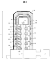
- FIG. 2 shows a cross-sectional view of an electron gun equipped with an acceleration tube according to an embodiment of the present invention.
- the electron gun 1 has a substantially axisymmetric structure with the electron beam 10 as an axis.
- the electron gun 1 includes a plurality of electrodes (121, 122, 123, 124) arranged along an irradiation direction of electrons from the electron source 11, and a plurality of insulator tubes (101) arranged between the plurality of electrodes. , 102, 103, 104, 105).
- a plurality of electrodes (121, 122, 123, 124) and a plurality of insulator tubes (101, 102, 103, 104, 105) are alternately stacked between the electron source 11 and the anode 125 having a ground potential.
- This whole laminated structure is called an acceleration tube structure. Both ends of the accelerating tube structure are a cathode 120 and an anode 125 having substantially the same potential as the electron source 11.
- the electrodes (121, 122, 123, 124) stacked between the cathode 120 and the anode 125 are called intermediate electrodes, respectively.
- the cathode 120, the electrodes (121, 122, 123, 124), and the anode 125 are connected to each other by resistors (130, 131, 132, 133, 134).
- a current corresponding to the potentials of the cathode 120 and the anode 125 always flows through the resistors (130, 131, 132, 133, 134).
- the resistors (130, 131, 132, 133, 134) function as bleeder resistors, and maintain the potentials of the electrodes (121, 122, 123, 124), which are intermediate electrodes, at equal intervals.
- the electrodes (121, 122, 123, 124) which are intermediate electrodes, at equal intervals.
- the resistors (130, 131, 132, 133, 134) function as bleeder resistors, and maintain the potentials of the electrodes (121, 122, 123, 124), which are intermediate electrodes, at equal intervals.
- the potentials are ⁇ 200 kV, ⁇ 160 kV, ⁇ 120 kV, ⁇ 80 kV, ⁇ 40 kV, and 0 kV, respectively.
- the inside of the accelerating tube structure is kept in a vacuum by the vacuum exhaust device 15 and becomes a passage for the electron beam 10 generated from the electron source 11.
- the stacked electrodes (121, 122, 123, 124) function as intermediate electrodes that give energy due to a potential difference to the passing electron beam 10.
- the electron beam 10 generated from the electron source 11 is sequentially accelerated through the accelerator tube structure to the anode 125 by the potential of the intermediate electrode.
- the periphery of the accelerating tube structure is surrounded by the housing 13.
- the housing 13 is formed of an insulating solid material, for example, a resin having high insulating performance.
- resin general resin, such as an epoxy, can be used.
- a conductive paint is applied to the outer surface 16 of the housing 13 and is at ground potential.
- an inner cathode 110 and a plurality of in-housing electrodes (111, 112, 113, 114) are provided on the inner surface of the resin housing 13.
- the in-housing cathode 110 is provided at a position facing the cathode 120 in the direction orthogonal to the electron beam 10.
- the in-housing electrodes (111, 112, 113, 114) are provided at positions facing the electrodes (121, 122, 123, 124) in the direction perpendicular to the electron beam 10, respectively.
- the in-housing cathode 110 corresponds to the cathode 120
- the in-housing electrodes (111, 112, 113, 114) correspond to the electrodes (121, 122, 123, 124), respectively.
- the corresponding electrodes are connected to each other by connection means (150, 151, 152, 153, 154) such as a metal spring in a state where the housing 13 is mounted around the accelerating tube structure. That is, when the housing 13 is attached around the accelerating tube structure, the cathode 120 and the in-housing cathode 110 are electrically connected to each other and have the same potential.
- the electrodes (121, 122, 123, 124) and the in-housing electrodes (111, 112, 113, 114) are electrically connected to each other, and the corresponding electrodes have the same potential.
- the portion of the resin housing 13 becomes a narrow portion (electric field concentration portion) of the equipotential lines, and the space 12 has a low electric field. Therefore, it is possible to prevent discharge from occurring between the high potential portion of the accelerating tube structure and the ground potential surface of the housing 13 by the resin having dielectric breakdown electric field characteristics.
- the resin is generally a substance having a higher dielectric breakdown electric field than vacuum, gas, or liquid. Therefore, the distance between the high potential portion of the accelerating tube structure and the ground potential surface of the housing 13 can be shortened and the overall structure can be reduced as compared with the case where insulation is performed using vacuum, insulating gas, or insulating liquid. Can do.
- the ground potential surface of the housing 13 (in this embodiment, the outer surface 16 of the housing 13) is to prevent discharge from occurring between the high potential portion of the accelerating tube structure and the ground potential surface of the housing 13.
- the space between the cathode in the housing and the electrodes (110, 111, 112, 113, 114) may be filled with resin. That is, the cathode and the electrodes (110, 111, 112, 113, 114) in the housing do not need to be completely embedded in the housing 13, and may be partially exposed.
- the connection part etc. with the connection means (150, 151, 152, 153, 154) in the electrode (111, 112, 113, 114) in a housing may be exposed.
- the in-housing electrodes (111, 112, 113, 114) are provided at positions facing the electrodes (121, 122, 123, 124), respectively, but are not limited to this configuration. It is not always necessary to provide the electrodes (111, 112, 113, 114) at opposing positions, and the in-housing electrodes (111, 112, 113, 114) are close to the electrodes (121, 122, 123, 124), respectively. What is necessary is just to be arrange
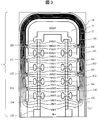
- FIG. 3 shows equipotential lines when a high voltage is applied to the electron gun in this embodiment.
- the cathode 120 is fixed at 200 kV and the electrodes (121, 122, 123, 124), that is, the intermediate electrode is fixed at 160 kV, 120 kV, 80 kV, and 40 kV, and the equipotential line position for every 10 kV is obtained by calculation. It is a thing.
- FIG. 3 shows that the cathode 120 and the in-housing cathode 110 have the same potential, and the corresponding electrodes of the electrodes (121, 122, 123, 124) and the in-housing electrodes (111, 112, 113, 114) have the same potential.
- the equipotential lines are narrow in the resin portion of the housing 13 and wide in the space 12 between the housing 13 and the acceleration tube structure. That is, when a structure having electrodes (an electrode in the housing and a cathode in the housing) is provided in the housing 13, a high electric field is generated in the resin portion of the housing 13 and a low electric field is generated in the space 12.
- the space 12 between the housing 13 and the accelerating tube structure is evacuated or encloses air, an insulating gas, or the like.
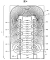
- FIG. 4 shows equipotential lines when a high voltage is applied to an electron gun provided with a metal housing that does not use resin as a comparison with the present embodiment.
- equipotential lines are distributed relatively uniformly in the space between the metal housing 40 and the cathode 120 and the electrodes 121, 122, 123, 124.
- the equipotential lines are narrower than in FIG. This means that a strong electric field exists in the space 41.
- the space 41 needs to be filled with an insulating material such as an insulating gas or an insulating liquid.
- an insulating material such as an insulating gas or an insulating liquid is used while making the space 41 wide. It is necessary to enclose. Therefore, in the structure of the conventional metal housing shown in FIG. 4, since the space 41 is widened, the entire size of the electron gun is increased, and the amount of insulating substances such as insulating gas and insulating liquid is increased. There is.
- the insulating gas or the insulating liquid is not used, or the amount of the insulating gas used can be reduced.
- the resin is generally a substance having a high dielectric breakdown electric field as compared with vacuum, insulating gas, and insulating liquid. Therefore, while designing the space between the ground potential surface of the housing and the accelerating tube structure to be narrow and providing a resin housing in the space, it is possible to prevent discharge and reduce the overall structure of the electron gun. it can.
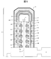
- FIG. 5 is a cross-sectional view of an electron gun having an acceleration tube structure according to a second embodiment of the present invention.
- an inner cathode 110 and a plurality of in-housing electrodes (111, 112, 113, 114) are provided on the inner surface of the resin housing 13.
- the difference from the embodiment of FIG. 2 is that the cathode 110 in the housing and the electrodes (111, 112, 113, 114) in the housing are connected by resistors (140, 141, 142, 143, 144), respectively. It is a point.
- the in-housing cathode 110 at the position where the potential difference is the largest with respect to the ground potential is connected to the cathode 120 by connection means 150 such as a metal spring.
- the resistance of the resistors (140, 141, 142, 143, 144) is set so that the electrodes facing each other have the same potential.
- the potentials applied to the cathode 120, the electrodes (121, 122, 123, 124), and the anode 125 are ⁇ 200 kV, ⁇ 160 kV, ⁇ 120 kV, ⁇ 80 kV, ⁇ 40 kV, and 0 kV, respectively.
- the resistance of the resistor 140 is set so that the potential of the in-housing electrode 111 is the same as the potential of the opposing electrode 121 ( ⁇ 160 kV).
- the potentials of the electrodes in the housing (112, 113, 114) are the same as the potentials of the opposing electrodes (122, 123, 124). Set to be.
- the cathode 120 and the in-housing cathode 110 have the same potential, and the corresponding electrodes of the electrode (121, 122, 123, 124) and the in-housing electrode (111, 112, 113, 114) have the same potential.
- the portion of the resin housing 13 becomes a narrow portion (electric field concentration portion) between equipotential lines, and a low electric field is generated in the space 12. Therefore, it is possible to prevent discharge from occurring in the space between the high potential portion of the acceleration tube structure and the ground potential of the housing 13 by the resin having dielectric breakdown electric field characteristics.
- the resin is generally a substance having a higher dielectric breakdown electric field than vacuum, gas, or liquid, the entire structure can be reduced as compared with the case of insulating with insulating gas or insulating liquid.
- the in-housing cathode 110 at the position where the potential difference is the largest with respect to the ground potential is connected to the facing cathode 120 by the connecting means 150, but the present invention is not limited to this configuration.
- some of the electrodes (ie, a plurality of electrodes) of the in-housing cathode 110 and the plurality of in-housing electrodes (111, 112, 113, 114) are respectively connected to the cathode 120 and the electrodes (121, 122, 123, 124), a plurality of in-housing electrodes (111, 112, 113, 114) that are connected to opposing electrodes and not connected to the opposing electrodes may be connected by resistors.
- the in-housing cathode 110 is electrically connected to the opposing cathode 120
- the in-housing electrode 111 is electrically connected to the electrode 121
- the remaining in-housing electrodes (112, 113, 114) have a plurality of You may make it connect with a resistor.
- FIG. 6 shows a cross-sectional view of a high voltage generator according to a third embodiment of the present invention.
- the present invention can be similarly used in a high-voltage device other than an electron gun, and can exhibit the same effect.
- FIG. 6 shows a cross-sectional view of a Cockcroft-Walton type high voltage generator 8.
- the high voltage generator 8 is a high voltage power generator included in the power source 51 of FIG. 1 in the electron microscope.
- the high voltage generator 8 has an electrode (867, 866, 865, 864, 863, 862, 861, 860) and an insulator (878, 877, 876, 875, 874, 873, 872, 871) are alternately stacked.
- the electrodes (867, 866, 865, 864, 863, 862, 861, 860) are electrically connected by a Cockcroft-Walton circuit 88.
- the Cockcroft-Walton circuit 88 is a circuit in which a high breakdown voltage capacitor 881 and a diode 882 are repeatedly connected in a predetermined order.
- an AC voltage is applied to the ground electrode 868 by an AC power source (not shown), whereby each electrode (867, 866, 865, 864, 863, 862, 861, 860) is sequentially boosted.
- a high voltage can be generated in the electrode 860 and the internal circuit portion 89.
- the electrode 860 and the internal circuit portion 89 are connected to the high voltage cable 81 via the connector 82.
- the high voltage generated in the electrode 860 and the internal circuit portion (high voltage generation portion) 89 is transmitted from the high voltage generation device 8 to a device such as the electron gun 1 by the connector 82 and the high voltage cable 81.
- These electrode rows (867, 866, 865, 864, 863, 862, 861, 860) are surrounded by a resin housing 83.
- a conductive paint is applied to the outer surface 84 of the housing 83 to be at a ground potential.
- housing inner electrodes (850, 851, 852, 853, 854, 855, 856, 857) are provided on the inner surface of the housing 83.
- the electrodes in the housing are respectively orthogonal to the stacking direction of the electrodes (860 to 867), and the electrodes (860, 861, 862, 863, 864, 865, 866, 867).
- the electrodes in the housing (850 to 857) and the electrodes (867 to 860) are connected to each other by connecting means (890, 891, 892, 893, 894, 895, 896, 897) such as a metal spring. Has been. Thereby, the electrodes which oppose are electrically connected and become the same electric potential. According to this configuration, as in the case of the electron gun 1 of FIGS. 2 and 4, a high electric field due to the generated high voltage is generated in the resin-made housing 83. Can be obtained, or a structure that can reduce the amount of use can be obtained. Conventionally, since the high voltage generator uses an insulating gas, an insulating liquid, or the like, the high voltage generator has been disposed of in the event of a failure. By providing the structure, the high voltage generator can be disassembled and the internal maintenance can be performed.
- the application example of the present invention is shown for the Cockcroft-Walton type high voltage generator, but the application example of the present invention is not limited thereto.
- the present invention can also be applied to other high voltage generators such as a bandegraph type.
- the electron gun 1 includes an electron source 11 that emits electrons, a cathode 120 and an anode 125, a plurality of electrodes (121, 122, 123, 124), and a plurality of insulator tubes (101). , 102, 103, 104, 105) and a housing 13 provided around the plurality of electrodes (121, 122, 123, 124).
- the housing 13 is formed of an insulating resin, and the housing 13 is opposed to the in-housing cathode 110 disposed at a position facing the cathode 120 and the plurality of electrodes (121, 122, 123, 124).
- a plurality of in-housing electrodes (111, 112, 113, 114) arranged at positions.
- the cathode in the housing and the electrodes (110, 111, 112, 113, 114) are respectively connected to the opposing electrodes (120, 121, 122, 122) by connection means (150, 151, 152, 153, 154) such as a metal spring. 123, 124).
- connection means 150, 151, 152, 153, 154
- the portion of the resin housing 13 becomes a narrow portion (electric field concentration portion) between equipotential lines, and a low electric field is generated in the space 12. Therefore, it is possible to prevent discharge from occurring in the space between the high potential portion of the accelerating tube structure and the ground potential of the housing 13 by the resin having high dielectric breakdown electric field characteristics.
- the resin is generally a substance having a higher dielectric breakdown electric field than vacuum, gas, or liquid, compared to the case where insulation is performed with vacuum, insulating gas, or insulating liquid, the resin is disposed between the housing 13 and the acceleration tube structure. It is possible to stably maintain a large potential difference while shortening the distance.
- the electron gun 1 can be further reduced in size, weight, and cost. Further, the housing 13 can be easily detached from the periphery of the acceleration tube structure, and can be attached again to the periphery of the acceleration tube structure. Therefore, maintenance inside the electron gun can be easily performed.
- the inner surface of the housing 13 is provided with the in-housing cathode 110 and a plurality of in-housing electrodes (111, 112, 113, 114).
- the cathode 110 in the housing is connected to the cathode 120 by a connecting means 150 such as a metal spring, and the cathode 110 in the housing and the electrodes (111, 112, 113, 114) in the housing are respectively resistors ( 140, 141, 142, 143, 144), and the resistances of the resistors (140, 141, 142, 143, 144) are set so that the electrodes facing each other have the same potential.
- the electrodes facing each other have the same potential without electrically connecting all the electrodes facing each other by a connecting means or the like. Accordingly, the portion of the resin housing 13 becomes a narrow portion (electric field concentration portion) of the equipotential lines, and a low electric field is generated in the space 12. Therefore, it is possible to prevent discharge from occurring in the space between the high potential portion of the accelerating tube structure and the ground potential of the housing 13 by the resin having high dielectric breakdown electric field characteristics.
- the resin is generally a substance having a higher dielectric breakdown electric field than vacuum, gas, or liquid, the entire structure can be reduced as compared with the case of insulating with insulating gas or insulating liquid.
- the Cockcroft-Walton type high voltage generator 8 includes a plurality of electrodes (867, 866, 865, 864, 863, 862, 861, 860) on the grounded ground electrode 868.
- a plurality of insulators (878, 877, 876, 875, 874, 873, 872, 871) are stacked, and the periphery of the stacked structure is surrounded by a housing 83.
- the housing 83 has a plurality of in-housing electrodes (850, 851, 852, 853, 854, 855, 856) at positions facing the plurality of electrode rows (867, 866, 865, 864, 863, 862, 861, 860). 857).
- a plurality of in-housing electrodes (850, 851, 852, 853, 854, 855, 856, 857) are opposed to each other by connecting means (890, 891, 892, 893, 894, 895, 896, 897). (867, 866, 865, 864, 863, 862, 861, 860). Thereby, the electrodes which oppose are electrically connected and become the same electric potential.
- the resin-made housing 83 since a high electric field due to the generated high voltage is generated in the resin-made housing 83, a discharge occurs in a space between the high-potential portion in the high-voltage generator 8 and the ground potential of the housing 83. Can be prevented.
- the resin is generally a substance having a higher dielectric breakdown electric field than vacuum, gas, or liquid, the entire structure can be reduced as compared with the case of insulating with insulating gas or insulating liquid.
- the high voltage generator uses an insulating gas, an insulating liquid, or the like, the high voltage generator has been disposed of in the event of a failure. By disposing, the high voltage generator can be disassembled and the internal maintenance can be performed.
- this invention is not limited to embodiment mentioned above, Various modifications are included.
- the above-described embodiment has been described in detail for easy understanding of the present invention, and is not necessarily limited to the one having all the configurations described.
- a part of the configuration of an embodiment may be replaced with the configuration of another embodiment, and the configuration of another embodiment may be added to the configuration of an embodiment.
- the in-housing electrode is provided at a position facing each electrode for all the electrodes, but the present invention is not limited to this configuration.
- the number of electrodes in the housing may be reduced.
- every other electrode may be provided for every other electrode.
- the application example of the present invention is shown for the electron gun and the cockcroft-Walton type high voltage generator having the acceleration tube structure.
- the application example of the present invention is not limited thereto. It is not limited.
- the present invention can also be applied to a general high-potential device in which a portion having a high potential exists therein, and a housing is provided around the high-potential portion.
- the high potential device includes a high potential portion where a high potential is generated, at least one first electrode disposed between the high potential portion and the ground potential plane, and the periphery of the high potential portion and the first electrode. And a housing.
- the housing is formed of an insulating solid material such as resin, and the housing has a plurality of second electrodes arranged corresponding to a predetermined potential interval from the ground potential surface to the high potential portion. And at least one of the plurality of second electrodes is electrically connected to the first electrode so that each of the plurality of second electrodes has the same potential as each potential in the predetermined potential interval. May be.
- the present invention can also be applied to a high-potential device having a laminated structure composed of an electrode and an insulating member between a high-potential portion and a portion that becomes a ground potential.
- the same structure as the resin housing having the above-mentioned housing internal electrode is applied to a device in which the intermediate electrode having the laminated structure has an intermediate potential between the high potential portion of the device and the ground potential. Can do. Thereby, it is possible to obtain a high potential device that does not use an insulating gas or the like or can reduce the amount of use.
- control lines and information lines in the drawings indicate what is considered necessary for the explanation, and not all control lines and information lines on the product are necessarily shown. All the components may be connected to each other.
- Electron gun 1 Electron gun 2 Electron optical system 3 Sample holder 4 Detector 5 Power supply part 6 Measurement part 7 Control apparatus 8 High voltage generator 10 Electron beam 11 Electron source 13 Housing 14 Accelerating tube 15 Vacuum exhaust apparatus 21 Vacuum exhaust apparatus 31 Sample 51 Power supply 110 In-housing cathode (second electrode) 111 to 114 Housing internal electrode (second electrode) 120 cathode (first electrode) 121-124 electrode (first electrode) 125 Anode (first electrode) 140 to 144 Resistors 150 to 154 Connecting means 81 High voltage cable 82 Connector 83 Housing 88 Cockcroft-Walton circuit 89 Circuit portion 860 Electrode 868 Ground electrode 881 Capacitor 882 Diode
Landscapes
- Chemical & Material Sciences (AREA)
- Analytical Chemistry (AREA)
- Physics & Mathematics (AREA)
- Optics & Photonics (AREA)
- Engineering & Computer Science (AREA)
- Combustion & Propulsion (AREA)
- Electron Sources, Ion Sources (AREA)
- Particle Accelerators (AREA)
Priority Applications (3)
| Application Number | Priority Date | Filing Date | Title |
|---|---|---|---|
| DE112013002551.5T DE112013002551T5 (de) | 2012-06-11 | 2013-05-08 | Vorrichtung zur Erzeugung eines Strahls geladener Teilchen, mit einem Strahl geladener Teilchen arbeitende Vorrichtung, Vorrichtung zur Erzeugung einer Hochspannung und mit einem hohen Potential arbeitende Vorrichtung |
| US14/406,909 US9548182B2 (en) | 2012-06-11 | 2013-05-08 | Charged particle beam generating apparatus, charged particle beam apparatus, high voltage generating apparatus, and high potential apparatus |
| CN201380030519.8A CN104364878A (zh) | 2012-06-11 | 2013-05-08 | 带电粒子束产生装置、带电粒子束装置、高电压产生装置以及高电位装置 |
Applications Claiming Priority (2)
| Application Number | Priority Date | Filing Date | Title |
|---|---|---|---|
| JP2012132103A JP5959326B2 (ja) | 2012-06-11 | 2012-06-11 | 荷電粒子ビーム発生装置、荷電粒子線装置、高電圧発生装置、および高電位装置 |
| JP2012-132103 | 2012-06-11 |
Publications (1)
| Publication Number | Publication Date |
|---|---|
| WO2013187155A1 true WO2013187155A1 (ja) | 2013-12-19 |
Family
ID=49757987
Family Applications (1)
| Application Number | Title | Priority Date | Filing Date |
|---|---|---|---|
| PCT/JP2013/062896 Ceased WO2013187155A1 (ja) | 2012-06-11 | 2013-05-08 | 荷電粒子ビーム発生装置、荷電粒子線装置、高電圧発生装置、および高電位装置 |
Country Status (5)
| Country | Link |
|---|---|
| US (1) | US9548182B2 (enExample) |
| JP (1) | JP5959326B2 (enExample) |
| CN (1) | CN104364878A (enExample) |
| DE (1) | DE112013002551T5 (enExample) |
| WO (1) | WO2013187155A1 (enExample) |
Families Citing this family (4)
| Publication number | Priority date | Publication date | Assignee | Title |
|---|---|---|---|---|
| JP2019003863A (ja) * | 2017-06-16 | 2019-01-10 | 株式会社島津製作所 | 電子ビーム装置、ならびに、これを備えるx線発生装置および走査電子顕微鏡 |
| US20230353056A1 (en) * | 2020-07-22 | 2023-11-02 | Hitachi High-Tech Corporation | DC High-Voltage Source Device and Charged Particle Beam Device |
| CN114867183A (zh) * | 2022-06-02 | 2022-08-05 | 上海守真北电子科技有限公司 | 一种高功率加速系统 |
| CN120584395A (zh) * | 2023-01-25 | 2025-09-02 | 佳能安内华股份有限公司 | X射线生成装置和x射线成像装置 |
Citations (3)
| Publication number | Priority date | Publication date | Assignee | Title |
|---|---|---|---|---|
| JPH0384839A (ja) * | 1989-08-28 | 1991-04-10 | Hitachi Ltd | 多段加速方式荷電粒子線加速装置 |
| JPH1092363A (ja) * | 1996-09-19 | 1998-04-10 | Jeol Ltd | 電子線用加速管 |
| JP2009193896A (ja) * | 2008-02-18 | 2009-08-27 | Hitachi High-Technologies Corp | 荷電粒子加速装置 |
Family Cites Families (14)
| Publication number | Priority date | Publication date | Assignee | Title |
|---|---|---|---|---|
| US3484866A (en) * | 1967-04-26 | 1969-12-16 | Nippon Electron Optics Lab | Direct current high voltage generator |
| JPS529971B2 (enExample) * | 1973-07-02 | 1977-03-19 | ||
| GB1503517A (en) * | 1974-09-10 | 1978-03-15 | Science Res Council | Electrostatic accelerators |
| JPH0766772B2 (ja) * | 1983-11-30 | 1995-07-19 | 株式会社日立製作所 | 多段加速方式電界放射形電子顕微鏡 |
| JP2796305B2 (ja) * | 1988-06-17 | 1998-09-10 | 株式会社日立製作所 | 電界放射電子銃 |
| US5059859A (en) * | 1989-04-14 | 1991-10-22 | Hitachi, Ltd. | Charged particle beam generating apparatus of multi-stage acceleration type |
| JP3091850B2 (ja) * | 1990-06-20 | 2000-09-25 | 株式会社日立製作所 | 荷電粒子線装置 |
| JPH0482150A (ja) * | 1990-07-24 | 1992-03-16 | Jeol Ltd | 電子線発生装置 |
| US5463268A (en) * | 1994-05-23 | 1995-10-31 | National Electrostatics Corp. | Magnetically shielded high voltage electron accelerator |
| CN1820346B (zh) * | 2003-05-09 | 2011-01-19 | 株式会社荏原制作所 | 基于带电粒子束的检查装置及采用了该检查装置的器件制造方法 |
| JP2006216396A (ja) | 2005-02-04 | 2006-08-17 | Hitachi High-Technologies Corp | 荷電粒子線装置 |
| JP2009289505A (ja) * | 2008-05-28 | 2009-12-10 | Hitachi Ltd | 電子線発生装置 |
| JP5023199B2 (ja) * | 2010-07-29 | 2012-09-12 | 株式会社日立ハイテクノロジーズ | 荷電粒子線放射装置 |
| US8558486B2 (en) * | 2010-12-08 | 2013-10-15 | Gtat Corporation | D. c. Charged particle accelerator, a method of accelerating charged particles using d. c. voltages and a high voltage power supply apparatus for use therewith |
-
2012
- 2012-06-11 JP JP2012132103A patent/JP5959326B2/ja not_active Expired - Fee Related
-
2013
- 2013-05-08 WO PCT/JP2013/062896 patent/WO2013187155A1/ja not_active Ceased
- 2013-05-08 US US14/406,909 patent/US9548182B2/en not_active Expired - Fee Related
- 2013-05-08 CN CN201380030519.8A patent/CN104364878A/zh active Pending
- 2013-05-08 DE DE112013002551.5T patent/DE112013002551T5/de not_active Withdrawn
Patent Citations (3)
| Publication number | Priority date | Publication date | Assignee | Title |
|---|---|---|---|---|
| JPH0384839A (ja) * | 1989-08-28 | 1991-04-10 | Hitachi Ltd | 多段加速方式荷電粒子線加速装置 |
| JPH1092363A (ja) * | 1996-09-19 | 1998-04-10 | Jeol Ltd | 電子線用加速管 |
| JP2009193896A (ja) * | 2008-02-18 | 2009-08-27 | Hitachi High-Technologies Corp | 荷電粒子加速装置 |
Also Published As
| Publication number | Publication date |
|---|---|
| CN104364878A (zh) | 2015-02-18 |
| JP2013257983A (ja) | 2013-12-26 |
| JP5959326B2 (ja) | 2016-08-02 |
| US9548182B2 (en) | 2017-01-17 |
| US20150179387A1 (en) | 2015-06-25 |
| DE112013002551T5 (de) | 2015-02-05 |
Similar Documents
| Publication | Publication Date | Title |
|---|---|---|
| CN108605405B (zh) | 双极x射线模块 | |
| EP2179436B1 (en) | Compact high voltage x-ray source system and method for x-ray inspection applications | |
| EP3923312B1 (en) | X-ray generation device and x-ray imaging device | |
| JP5713832B2 (ja) | 放射線発生装置及びそれを用いた放射線撮影装置 | |
| JP5959326B2 (ja) | 荷電粒子ビーム発生装置、荷電粒子線装置、高電圧発生装置、および高電位装置 | |
| US20180054879A1 (en) | Cylindrical high voltage arrangement for a miniature x-ray system | |
| JP2013520775A (ja) | Dc高電圧源及び粒子加速器 | |
| KR102252811B1 (ko) | X선 발생 장치 및 x선 촬영 시스템 | |
| WO2025057790A1 (ja) | X線発生装置およびx線撮像装置 | |
| CN106165282A (zh) | 电源单元 | |
| JP6612453B2 (ja) | X線放射装置に関するターゲットアセンブリ及びx線放射装置 | |
| JP2010015818A (ja) | 電子源装置及びイオン装置 | |
| JP2011171296A (ja) | イオンを集束および蓄積する装置、および圧力領域を分離する装置 | |
| US20050190884A1 (en) | X-ray source and a nondestructive inspector | |
| JP2013257983A5 (enExample) | ||
| KR102515761B1 (ko) | 엑스레이 튜브 | |
| US7085353B2 (en) | X-ray tube | |
| US12283452B2 (en) | Charged particle beam apparatus | |
| JP6840603B2 (ja) | 核融合中性子発生装置 | |
| JP2013178878A (ja) | コッククロフト・ウォルトン回路を用いた高電圧発生装置、及び荷電粒子線装置 | |
| TWI822116B (zh) | 放電檢測裝置以及帶電粒子束照射裝置 | |
| JP6570972B2 (ja) | 核融合中性子発生装置および核融合中性子発生方法 | |
| JP2008269915A (ja) | 高電圧電源装置及びその耐放電性確保方法 | |
| JP2018170091A (ja) | X線管装置 | |
| Lehr et al. | Streamer initiation in volume and surface discharges in atmospheric gases |
Legal Events
| Date | Code | Title | Description |
|---|---|---|---|
| 121 | Ep: the epo has been informed by wipo that ep was designated in this application |
Ref document number: 13804506 Country of ref document: EP Kind code of ref document: A1 |
|
| WWE | Wipo information: entry into national phase |
Ref document number: 14406909 Country of ref document: US Ref document number: 112013002551 Country of ref document: DE Ref document number: 1120130025515 Country of ref document: DE |
|
| 122 | Ep: pct application non-entry in european phase |
Ref document number: 13804506 Country of ref document: EP Kind code of ref document: A1 |